EP2692634A1 - Système et procédé pour augmenter la puissance d'un hélicoptère - Google Patents
Système et procédé pour augmenter la puissance d'un hélicoptère Download PDFInfo
- Publication number
- EP2692634A1 EP2692634A1 EP12182851.1A EP12182851A EP2692634A1 EP 2692634 A1 EP2692634 A1 EP 2692634A1 EP 12182851 A EP12182851 A EP 12182851A EP 2692634 A1 EP2692634 A1 EP 2692634A1
- Authority
- EP
- European Patent Office
- Prior art keywords
- power
- drive system
- aircraft
- engine
- augmentation device
- Prior art date
- Legal status (The legal status is an assumption and is not a legal conclusion. Google has not performed a legal analysis and makes no representation as to the accuracy of the status listed.)
- Granted
Links
Images




Classifications
-
- B—PERFORMING OPERATIONS; TRANSPORTING
- B64—AIRCRAFT; AVIATION; COSMONAUTICS
- B64C—AEROPLANES; HELICOPTERS
- B64C27/00—Rotorcraft; Rotors peculiar thereto
- B64C27/04—Helicopters
- B64C27/12—Rotor drives
-
- B—PERFORMING OPERATIONS; TRANSPORTING
- B64—AIRCRAFT; AVIATION; COSMONAUTICS
- B64D—EQUIPMENT FOR FITTING IN OR TO AIRCRAFT; FLIGHT SUITS; PARACHUTES; ARRANGEMENT OR MOUNTING OF POWER PLANTS OR PROPULSION TRANSMISSIONS IN AIRCRAFT
- B64D27/00—Arrangement or mounting of power plants in aircraft; Aircraft characterised by the type or position of power plants
- B64D27/02—Aircraft characterised by the type or position of power plants
- B64D27/30—Aircraft characterised by electric power plants
- B64D27/33—Hybrid electric aircraft
-
- B—PERFORMING OPERATIONS; TRANSPORTING
- B64—AIRCRAFT; AVIATION; COSMONAUTICS
- B64D—EQUIPMENT FOR FITTING IN OR TO AIRCRAFT; FLIGHT SUITS; PARACHUTES; ARRANGEMENT OR MOUNTING OF POWER PLANTS OR PROPULSION TRANSMISSIONS IN AIRCRAFT
- B64D31/00—Power plant control systems; Arrangement of power plant control systems in aircraft
- B64D31/16—Power plant control systems; Arrangement of power plant control systems in aircraft for electric power plants
- B64D31/18—Power plant control systems; Arrangement of power plant control systems in aircraft for electric power plants for hybrid-electric power plants
-
- B—PERFORMING OPERATIONS; TRANSPORTING
- B64—AIRCRAFT; AVIATION; COSMONAUTICS
- B64D—EQUIPMENT FOR FITTING IN OR TO AIRCRAFT; FLIGHT SUITS; PARACHUTES; ARRANGEMENT OR MOUNTING OF POWER PLANTS OR PROPULSION TRANSMISSIONS IN AIRCRAFT
- B64D35/00—Transmitting power from power plants to propellers or rotors; Arrangements of transmissions
- B64D35/02—Transmitting power from power plants to propellers or rotors; Arrangements of transmissions specially adapted for specific power plants
- B64D35/021—Transmitting power from power plants to propellers or rotors; Arrangements of transmissions specially adapted for specific power plants for electric power plants
- B64D35/022—Transmitting power from power plants to propellers or rotors; Arrangements of transmissions specially adapted for specific power plants for electric power plants of hybrid-electric type
-
- B—PERFORMING OPERATIONS; TRANSPORTING
- B64—AIRCRAFT; AVIATION; COSMONAUTICS
- B64D—EQUIPMENT FOR FITTING IN OR TO AIRCRAFT; FLIGHT SUITS; PARACHUTES; ARRANGEMENT OR MOUNTING OF POWER PLANTS OR PROPULSION TRANSMISSIONS IN AIRCRAFT
- B64D27/00—Arrangement or mounting of power plants in aircraft; Aircraft characterised by the type or position of power plants
- B64D27/02—Aircraft characterised by the type or position of power plants
- B64D27/026—Aircraft characterised by the type or position of power plants comprising different types of power plants, e.g. combination of a piston engine and a gas-turbine
-
- Y—GENERAL TAGGING OF NEW TECHNOLOGICAL DEVELOPMENTS; GENERAL TAGGING OF CROSS-SECTIONAL TECHNOLOGIES SPANNING OVER SEVERAL SECTIONS OF THE IPC; TECHNICAL SUBJECTS COVERED BY FORMER USPC CROSS-REFERENCE ART COLLECTIONS [XRACs] AND DIGESTS
- Y02—TECHNOLOGIES OR APPLICATIONS FOR MITIGATION OR ADAPTATION AGAINST CLIMATE CHANGE
- Y02T—CLIMATE CHANGE MITIGATION TECHNOLOGIES RELATED TO TRANSPORTATION
- Y02T50/00—Aeronautics or air transport
- Y02T50/60—Efficient propulsion technologies, e.g. for aircraft
Definitions
- the present application relates in general to power generation in aircraft. More specifically, the present application relates to selective power augmentation within the drive system.
- Aircraft engines within a drive system generate sufficient power to permit flight. Some maneuvers, such as takeoffs, auto-rotation, and landing, can require a greater amount of power from the engines than typically required in regular flight. Aircraft engines are sized to be able to generate this needed power at selected times and typically in short bursts. Because these maneuvers usually consist of a relatively small portion of the operational time of the aircraft, engines are regularly oversized.
- rotorcraft engines generally operate at a medium speed so as to deliver a medium power, e.g. the so-called maximum continuous power for a helicopter.
- a medium power e.g. the so-called maximum continuous power for a helicopter.
- aircraft engines are sometimes called upon to deliver higher power for a short period, such as maximum takeoff power for a helicopter.
- the need to deliver increased power output at selected times results in aircraft engines typically being oversized relative to medium power operation. This results in less efficiency, more fuel consumption, and greater weight on the aircraft.
- Rotorcraft 101 having a regenerative drive system 201 is illustrated.
- Rotorcraft 101 has a rotor system 103 with a plurality of rotor blades 111.
- the pitch of each rotor blade 111 can be selectively controlled in order to selectively control direction, thrust, and lift of rotorcraft 101.
- Rotorcraft 101 further includes a fuselage 105, landing gear 107, and a tail member 109.
- Tiltrotor aircraft 151 includes a fuselage 157, a landing gear 159, a wing 155, and rotatable nacelles 153a and 153b.
- Each nacelle 153a and 153b includes a plurality of rotor systems 161, each having a plurality of rotor blades 163.
- the position of nacelles 153a and 153b, as well as the pitch of rotor blades 163, can be selectively controlled in order to selectively control direction, thrust, and lift of tiltrotor aircraft 151.
- Tiltrotor aircraft 151 also includes regenerative drive system 201 to selectively augment power provided to tiltrotor aircraft 151. It is understood that regenerative drive system 201 may or may not be designed to be rotatable with rotor system 161. Furthermore regenerative drive system 201 may be used with aircraft having one or more sets of rotor systems 103, 161.
- rotorcraft 101 and tiltrotor aircraft 151 are both aircraft.
- aircraft is not so narrow as to be limited by these types of aircraft.
- aircraft may include any machine supported for flight in the air, by buoyancy, or by the dynamic action of air on its surfaces.
- Examples of possible aircraft include powered airplanes, gliders, tiltrotors, and rotorcraft such as helicopters and compound helicopters. Therefore the term "aircraft” will relate to rotorcraft 101, tiltrotor aircraft 151, and all other forms of aircraft.
- Drive system 201 includes the use of an engine 207, a transmission 205, a driveshaft 213, and a power augmentation device 209 to selectively provide supplemental power to the aircraft with or without an overrunning clutch.
- System 201 may be used with or without an overrunning clutch in all the embodiments described and taught within this application.
- Drive system 201 may be used with single engine aircraft or multiple engine aircraft.
- Figures 4-6 illustrate the use of drive system 201 with a multiple engine aircraft.
- Engine 207 is coupled to transmission 205 by a single driveshaft 213.
- Engine 207 is configured to rotate driveshaft 213, which in turn rotates within transmission 205. This rotational energy is harnessed by transmission 205 and used to rotate rotor system 103, 161.
- Engine 207 is configured to generate power that is transmitted to the transmission and other systems on the aircraft.
- Engine power can be used in different forms.
- Engine 207 assists in the production of mechanical and electrical power used to run the various systems on the aircraft, for example: pumps and blowers.
- engine 207 produces mechanical power transmitted through a rotating driveshaft 213 to transmission 205.
- Driveshaft 213 extends between, and is coupled to, both transmission 205 and engine 207.
- Transmission 205 receives and directs the engine power provided through driveshaft 213 to provide rotational energy to rotor system 103, 161 through one or more main rotor shafts 211.
- Transmission 205 is coupled to the aircraft via an airframe 203a, 203b.
- Drive system 201 is configured to selectively store power and provide selectively controlled power bursts, or a release of power, during emergency conditions and/or special operating conditions through the use of device 209 as opposed to power output solely from engine 207. This power is obtained by taking power produced by engine 207 and storing the power for future use.
- the power bursts provide the necessary additional power required to perform critical flight maneuvers, such as a safe landing or a balked landing followed by a climb-out with the remaining engine.
- the power burst provided by device 209 either supplements engine 207 and/or provides power in place of engine 207 to perform critical flight maneuvers.
- Power augmentation device 209 is a device that selectively stores energy on-demand and then selectively provides the stored energy to any number of sources. Power augmentation device 209 provides the power bursts by releasing stored power back into drive system 201 for use in rotor system 103, 161 or other flight control systems on the aircraft.
- device 209 can be a kinetic energy recovery system used to supply mechanical or electrical power to the aircraft.
- Device 209 is coupled to driveshaft 213 operatively coupled between transmission 205 and engine 207.
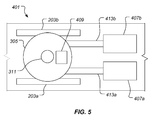
- Device 209 selectively engages a portion of driveshaft 213 without interfering with the direct coupling of engine 207 and transmission 205. This feature permits device 209 to be installed and/or removed from existing drive systems, as a retrofit application, for example. Although described as being coupled to driveshaft 213, it is understood that device 209 may be coupled to any location in mechanical communication with engine 207. For example, device 209 may be located within transmission 205, as seen in Figure 5 .
- Device 209 may operate in a number of ways. First device 209 is configured to spin-up, meaning to selectively charge or store up power. Secondly, device 209 is configured to timely release a power burst, meaning producing a controlled power output. Each operation is done under controlled conditions.
- spin-up occurs during times of an emergency, such as when one engine is failing, unresponsive, or shut down.
- spin-up can also occur during special operating conditions, such as flight specific and mission specific maneuvers.
- An example of a special operating condition is a Category A takeoff. Under such a maneuver, a critical decision point (height above the ground) is defined for which a continued takeoff can be accomplished following the complete failure of one engine. The critical decision point is based upon a total energy concept involving kinetic energy (airspeed) and potential energy (height).
- a special operating condition it is preferred that device 209 has been charged prior to performing the maneuver. Therefore, device 209 is configured to spin-up during and/or before the emergency and special operating conditions. This can have an effect on the determination of the critical decision point for the aircraft.
- Device 209 selectively alternates between a plurality of orientations to timely and selectively store power.
- a first orientation device 209 is disengaged from driveshaft 213. This means that the charging elements of device 209 are separated from members of drive system 201 so as to reduce drag and prevent spin-up.
- a second orientation device 209 engages members of drive system 201 while engine 207 is operating in order to generate stored power.
- This stored power may be in the form of electrical energy, in a battery for example, or in the form of mechanical energy in the use of springs or flywheels, for example.
- device 209 Under normal operation, when engine 207 is fully operational, device 209 is disengaged from driveshaft 213. When engine 207 begins to fail or in case of an emergency, device 209 engages driveshaft 213 and begins to store power in case the time comes to release the power back into system 201 and/or the aircraft in the form of a power burst in order to perform a critical flight maneuver. Under special operating conditions, device 209 may engage driveshaft 213 and immediately provide the power burst if device 209 was spun-up prior to performing the maneuver. After spin-up is complete and prior to delivering the power burst, device 209 may selectively disengage from driveshaft 213.
- An advantage to having device 209 selectively engage and disengage from driveshaft 213 is that drag on driveshaft 213 is reduced when device 209 is not being used. When disengaged, power is not able to be collected in device 209 and the driveshaft is permitted to freely spin without additional drag from device 209.
- device 209 may be configured to continuously engage driveshaft 213.
- device 209 is configured, so as to maintain a continuously stored amount of power for use in emergency and/or special operating conditions like the Category A maneuver.
- the drag on driveshaft 213 is continuous and leads to a less efficient operation of system 201 during normal operating conditions.
- device 209 can be configured with a clutch mechanism having frictionless bearings. However, it is understood that device 209 may be configured to refrain from collecting and/or storing energy until an emergency situation arises.
- system 201 is configured to release selected amounts of stored power from device 209 back into system 201 and/or the aircraft.
- device 209 may release selected amounts of power automatically in order to maintain critical flight systems and/or perform critical flight maneuvers.
- the amount of power released back into drive system 201 and the aircraft may be regulated by flight control systems in order to conserve power and to provide for the accurate and timely distribution of power within the systems of the aircraft.
- the flight control system may selectively control the magnitude and duration of stored power being stored and released, the system receiving the power burst, as well as the timing of the power burst.
- device 209 may store and release power based upon commands from a pilot and/or crewmember of the aircraft.
- the pilot and/or crewmember may selectively control the magnitude and duration of stored power released, the system receiving the power burst, and the timing of the power burst.
- the power burst may be in the form of additional mechanical power and/or electrical power provided to flight systems within the aircraft.
- the duration and magnitude of the power burst may be regulated.
- the power burst may be intermittent in that device 209 may engage and disengage to provide multiple power bursts. Additionally, it is understood that device 209 may spin-up multiple times during an emergency condition and/or special operating condition. Likewise, device 209 may recharge or spin-up multiple times before discharging all the stored power.
- device 209 is configured as a self contained unit in which device 209 contains all the necessary parts to collect and store the power from members of drive system 201, and to discharge stored power to drive system 201. It is understood that device 209 may contain multiple units permitting the repair and replacement of specific units within device 209.
- system 201 will activate or deactivate device 209 automatically as controlled by automated flight control systems on the aircraft.
- device 209 uses any number of sensors from existing flight control systems to measure the performance of engine 207. When performance has deteriorated to a predetermined point, or when the condition of engine 207 is deteriorating at a predetermined rate, engine 207 is considered to have failed and system 201 automatically engages and disengages device 209 to collect, store, and discharge stored power.
- Device 209 is configured to spin-up to full power within a selected time limit.
- device 209 can be configured to take 8 seconds to store full power. This time limit may vary depending on many factors. Design constraints and aircraft capabilities, among others, are to be considered in the sizing of device 209.
- device 209 may be capable of producing 20 horsepower for a duration of 30 seconds.
- a larger power augmentation device 209 may have a production capability larger than 20 horsepower for a duration other than 30 seconds.
- Drive system 301 is a dual engine drive system for one or more main rotor shafts 311.
- the elements of drive system 301 are similar in form and function to that of those described in drive system 201 except as noted herein.
- Drive system 301 differs with respect to several areas as will be described in further detail.
- Drive system 301 includes a first engine 307a and a second engine 307b, a single torque-combining gearbox (cobox) 317, a power augmentation device 309, and a transmission 305.
- Three separate shafts are used within drive system 301, namely a first gearbox input shaft 313a, a second gearbox input shaft 313b, and a main driveshaft 315.
- a key performance parameter for multiple engine aircraft drive systems is the ability to operate under a One Engine Inoperative (OEI) condition. Under such conditions, an aircraft engine becomes unresponsive, fails or is shut down, resulting in the aircraft using only a single engine.
- the second, or additional, engines are designed to have a given OEI rating.
- the OEI rating refers to a measure of time that the remaining engine can produce a desired amount of additional power (power burst) if one engine becomes unresponsive, fails or is shut down during a critical flight maneuver, such as takeoff, rejected takeoff, or landing, for example. This additional power burst is required to meet the minimum power requirement and is intended for execution of the critical flight maneuver.
- an OEI rating may be for thirty seconds of additional supplemental power.
- Device 309 and similarly device 209 are configured to provide power bursts as needed, so as to allow engines 307a, 307b, 207 to be optimized and sized for efficiency.
- Drive system 301 has multiple engines 307a, 307b and a single device 309 to provide power bursts.
- each engine 307a, 307b is operably coupled to cobox 317 through input shafts 313a, 313b respectively.
- Cobox 317 is configured to receive the input shafts of engines 307a, 307b and combine the power into the single main driveshaft 315 that feeds power to transmission 305.
- Device 309 is coupled to main driveshaft 315 between cobox 317 and transmission 305. As one of engines 307a, 307b fails, a single device 309 is able to provide power rather than requiring additional power augmentation devices.
- a drive system 401 is illustrated as another embodiment of drive system 201.
- Drive system 401 illustrates another configuration wherein a single power augmentation device is used with multiple engines.
- Drive system 401 includes a first engine 407a, a second engine 407b, a first driveshaft 413a, a second driveshaft 413b, a power augmentation device 409, and transmission 305.
- Drive system 401 is a dual engine drive system for a single rotor system 103.
- the elements of drive system 401 are similar in form and function to that of those described in drive system 201 except as noted herein.
- Drive system 401 differs with respect to a couple areas as will be described in further detail.
- each engine 407a, 407b is directly coupled to transmission 305 through driveshafts 313a, 313b, respectively.
- Device 409 is located within transmission 305. In this embodiment, device 409 may be operably coupled and configured to engage and disengage transmission 305 directly. This configuration successfully removes the need to have cobox 317.
- Transmission 305 is configured to receive and combine the power generated from each engine 407a, 407b for use in main rotor shaft 311.
- Device 409 is coupled within transmission 305 between main rotor shaft 311 and the point of combining driveshafts 413a, 413b within transmission 305.
- a drive system 501 is illustrated as another embodiment of drive system 201.
- Drive system 501 illustrates a configuration wherein multiple power augmentation devices are used with multiple engines.
- the elements of drive system 501 are similar in form and function to that of those described in drive system 201 except as noted herein.
- drive system 501 is structurally similar to that of drive system 401, wherein each engine has a driveshaft directly coupled to transmission 305.
- drive system 501 differs in having a power augmentation device 509a, 509b for each engine 507a, 507b respectively.
- Drive system 501 includes a first engine 507a, a second engine 507b, a first driveshaft 513a, a second driveshaft 513b, first power augmentation device 509a, second power augmentation device 509a, and transmission 305.
- Devices 509a, 509b are coupled to driveshafts 513a, 513b as opposed to being located within transmission 305 as seen in drive system 401.
- Devices 509a, 509b operate similarly in form and function as described with device 209.
- Drive system 501 is configured to spin-up one or both devices 509a, 509b similarly to that described with device 209. Additionally, drive system 501 is configured to determine which device 509a, 509b is selected to spin-up, the device coupled to the good remaining engine or that of the failed or failing engine.
- Devices 509a, 509b may be in electrical or mechanical communication so as to share power between themselves. In such an embodiment, a fully operable remaining engine may be used to spin-up both devices 509a, 509b.
- drive system 501 may use a plurality of power augmentation devices coupled in any mechanical formation.
- the devices are coupled mechanically in a series formation along a single drive shaft.
- the method includes use of an aircraft that has a drive system, including an engine, transmission, and a driveshaft 603.
- the aircraft has a power augmentation device that is installed within the drive system either upon the original manufacture of the aircraft or upon a retrofit operation after final build.
- Flight control systems within the aircraft are configured to monitor the power output of the engines. When a single engine is determined to have failed, become unresponsive, or is shut down prior to an emergency or special operating condition, the system or the pilot may relay a command to engage the power augmentation device to the drive system 605. This engagement allows for the device to spin-up and store power for use during critical flight maneuvers 607.
- the power within the device may be released back into the drive system or control systems of the aircraft as desired by the pilot or proscribed by the flight control systems 609.
- the device may be re-engaged as needed to acquire and provide the necessary power burst, so as to provide a plurality of separate and distinct power bursts.
- the systems and methods of the present application provides significant advantages, including: (1) more optimally sized engines for use of aircraft; (2) decreased emissions and increased fuel efficiency; (3) selective power storage sufficient to enable an aircraft to perform critical flight maneuvers; and (4) a hybrid drive system for an aircraft that supplements engine power during emergency conditions.
Landscapes
- Engineering & Computer Science (AREA)
- Aviation & Aerospace Engineering (AREA)
- Mechanical Engineering (AREA)
- Transmission Devices (AREA)
- General Details Of Gearings (AREA)
- Electric Propulsion And Braking For Vehicles (AREA)
Applications Claiming Priority (1)
| Application Number | Priority Date | Filing Date | Title |
|---|---|---|---|
| US13/563,086 US8939399B2 (en) | 2012-07-31 | 2012-07-31 | System and method of augmenting power in a rotorcraft |
Publications (2)
| Publication Number | Publication Date |
|---|---|
| EP2692634A1 true EP2692634A1 (fr) | 2014-02-05 |
| EP2692634B1 EP2692634B1 (fr) | 2015-05-27 |
Family
ID=46799125
Family Applications (1)
| Application Number | Title | Priority Date | Filing Date |
|---|---|---|---|
| EP12182851.1A Active EP2692634B1 (fr) | 2012-07-31 | 2012-09-03 | Système et procédé pour augmenter la puissance d'un hélicoptère |
Country Status (4)
| Country | Link |
|---|---|
| US (1) | US8939399B2 (fr) |
| EP (1) | EP2692634B1 (fr) |
| CN (1) | CN103569368B (fr) |
| CA (1) | CA2821104C (fr) |
Cited By (3)
| Publication number | Priority date | Publication date | Assignee | Title |
|---|---|---|---|---|
| EP3197773A4 (fr) * | 2014-09-23 | 2018-02-21 | Sikorsky Aircraft Corporation | Système d'entraînement de puissance électrique hybride pour un giravion |
| EP3670339A1 (fr) | 2018-12-20 | 2020-06-24 | Airbus Helicopters | Procede d'assistance pour aeronef monomoteur a voilure tournante lors d'une panne moteur |
| EP3967598A1 (fr) | 2020-09-14 | 2022-03-16 | Airbus Helicopters | Procédé et dispositif de gestion de l'énergie fournie par une installation motrice hybride pour giravion |
Families Citing this family (62)
| Publication number | Priority date | Publication date | Assignee | Title |
|---|---|---|---|---|
| US9376206B2 (en) | 2013-03-12 | 2016-06-28 | Bell Helicopter Textron Inc. | Tiltrotor aircraft with inboard wing mounted fixed engine arrangement |
| US9126678B2 (en) * | 2013-03-13 | 2015-09-08 | Bell Helicopter Textron Inc. | Spindle mounted tiltrotor pylon with fixed engine arrangement |
| US9180964B2 (en) | 2013-03-15 | 2015-11-10 | Bell Helicopter Textron Inc. | Autorotative enhancement system |
| US10569892B2 (en) * | 2013-05-06 | 2020-02-25 | Sikorsky Aircraft Corporation | Supplemental power for reduction of prime mover |
| US9663225B1 (en) | 2013-08-14 | 2017-05-30 | Bell Helicopter Textron Inc. | Maintaining drive system alignment in tiltrotor aircraft |
| US9856029B2 (en) | 2013-08-14 | 2018-01-02 | Bell Helicopter Textron Inc. | Tiltrotor aircraft having tip rib mounted pylon assemblies |
| US9868541B2 (en) | 2013-08-14 | 2018-01-16 | Bell Helicopter Textron Inc. | Tiltrotor aircraft having journal bearing mounted pylon assemblies |
| US9809318B1 (en) | 2013-08-14 | 2017-11-07 | Bell Helicopter Textron Inc. | Tiltrotor aircraft having spherical bearing mounted pylon assemblies |
| US9868542B2 (en) | 2013-08-14 | 2018-01-16 | Bell Helicopter Textron Inc. | Tiltrotor aircraft having pillow block mounted pylon assemblies |
| WO2016049030A1 (fr) * | 2014-09-23 | 2016-03-31 | Sikorsky Aircraft Corporation | Système d'entrainement d'énergie de contingence hybride |
| FR3027346B1 (fr) * | 2014-10-20 | 2019-08-09 | Safran Helicopter Engines | Pack amovible de reactivation d'un turbomoteur, architecture d'un systeme propulsif d'un helicoptere multi-moteur equipe d'un tel pack et helicoptere correspondant |
| CN104627362B (zh) * | 2014-11-04 | 2019-05-28 | 章水清 | 直升机应用伺服子盘型活塞航空发动机强化安全自转着陆 |
| US10000293B2 (en) | 2015-01-23 | 2018-06-19 | General Electric Company | Gas-electric propulsion system for an aircraft |
| WO2016164206A1 (fr) * | 2015-04-09 | 2016-10-13 | Sikorsky Aircraft Corporation | Système de déclenchement d'autorotation |
| FR3036235B1 (fr) | 2015-05-15 | 2018-06-01 | Airbus Helicopters | Procede pour activer un moteur electrique d'une installation hybride d'un aeronef multimoteur et un aeronef |
| CN105173071A (zh) * | 2015-07-31 | 2015-12-23 | 章水清 | 一种主辅动力一体可弃的伺服子盘型直升机用活塞发动机 |
| US9637217B2 (en) | 2015-09-21 | 2017-05-02 | General Electric Company | Aircraft having an aft engine |
| US9815560B2 (en) | 2015-09-21 | 2017-11-14 | General Electric Company | AFT engine nacelle shape for an aircraft |
| US9821917B2 (en) | 2015-09-21 | 2017-11-21 | General Electric Company | Aft engine for an aircraft |
| US9884687B2 (en) | 2015-09-21 | 2018-02-06 | General Electric Company | Non-axis symmetric aft engine |
| US9957055B2 (en) | 2015-09-21 | 2018-05-01 | General Electric Company | Aft engine for an aircraft |
| US10017270B2 (en) | 2015-10-09 | 2018-07-10 | General Electric Company | Aft engine for an aircraft |
| US9764848B1 (en) | 2016-03-07 | 2017-09-19 | General Electric Company | Propulsion system for an aircraft |
| US10392119B2 (en) | 2016-04-11 | 2019-08-27 | General Electric Company | Electric propulsion engine for an aircraft |
| US10252810B2 (en) | 2016-04-19 | 2019-04-09 | General Electric Company | Propulsion engine for an aircraft |
| US10392120B2 (en) | 2016-04-19 | 2019-08-27 | General Electric Company | Propulsion engine for an aircraft |
| US10676205B2 (en) | 2016-08-19 | 2020-06-09 | General Electric Company | Propulsion engine for an aircraft |
| US10800539B2 (en) * | 2016-08-19 | 2020-10-13 | General Electric Company | Propulsion engine for an aircraft |
| US11105340B2 (en) | 2016-08-19 | 2021-08-31 | General Electric Company | Thermal management system for an electric propulsion engine |
| US10308366B2 (en) | 2016-08-22 | 2019-06-04 | General Electric Company | Embedded electric machine |
| US10093428B2 (en) | 2016-08-22 | 2018-10-09 | General Electric Company | Electric propulsion system |
| US10487839B2 (en) | 2016-08-22 | 2019-11-26 | General Electric Company | Embedded electric machine |
| US10071811B2 (en) | 2016-08-22 | 2018-09-11 | General Electric Company | Embedded electric machine |
| US10793281B2 (en) | 2017-02-10 | 2020-10-06 | General Electric Company | Propulsion system for an aircraft |
| US10822103B2 (en) | 2017-02-10 | 2020-11-03 | General Electric Company | Propulsor assembly for an aircraft |
| US11149578B2 (en) | 2017-02-10 | 2021-10-19 | General Electric Company | Propulsion system for an aircraft |
| CN107010229A (zh) * | 2017-03-22 | 2017-08-04 | 重庆大学 | 双发油动无人机 |
| US10137981B2 (en) | 2017-03-31 | 2018-11-27 | General Electric Company | Electric propulsion system for an aircraft |
| US10807729B2 (en) * | 2017-05-17 | 2020-10-20 | General Electric Company | Propulsion system for an aircraft |
| US10762726B2 (en) | 2017-06-13 | 2020-09-01 | General Electric Company | Hybrid-electric propulsion system for an aircraft |
| US10703462B2 (en) | 2017-08-25 | 2020-07-07 | Hamilton Sunstrand Corporation | Flight control system regenerative braking |
| US11001384B2 (en) | 2017-10-02 | 2021-05-11 | Bell Helicopter Textron Inc. | Hybrid power systems for aircraft |
| US10906656B2 (en) | 2018-05-01 | 2021-02-02 | Bell Textron Inc. | Hybrid tiltrotor drive system |
| US11148798B2 (en) * | 2018-06-22 | 2021-10-19 | Textron Innovations Inc. | Engine and rotatable proprotor configurations for a tiltrotor aircraft |
| US10913542B2 (en) * | 2018-07-27 | 2021-02-09 | Textron Innovations Inc. | Conversion actuator and downstop striker fitting for a tiltrotor aircraft |
| US10994839B2 (en) | 2018-07-31 | 2021-05-04 | Textron Innovations Inc. | System and method for rotating a rotor of a tiltrotor aircraft |
| US11022213B2 (en) * | 2018-08-20 | 2021-06-01 | Bell Helicopter Textron Inc. | Variable-speed gear box with hydraulic system for tiltrotor aircraft |
| US11156128B2 (en) | 2018-08-22 | 2021-10-26 | General Electric Company | Embedded electric machine |
| US11097849B2 (en) | 2018-09-10 | 2021-08-24 | General Electric Company | Aircraft having an aft engine |
| US20200180771A1 (en) | 2018-12-06 | 2020-06-11 | General Electric Company | Thermal Management System for an Aircraft Including an Electric Propulsion Engine |
| US10815904B2 (en) | 2019-03-06 | 2020-10-27 | General Electric Company | Prognostic health management control for adaptive operability recovery for turbine engines |
| US11613375B2 (en) * | 2019-05-16 | 2023-03-28 | Textron Innovations Inc. | Dual motor input with overrunning clutch |
| US11673474B2 (en) | 2019-12-31 | 2023-06-13 | Textron Innovations Inc. | Controlling regenerative braking to reduce skidding of a vehicle |
| US11408340B2 (en) * | 2020-05-15 | 2022-08-09 | Pratt & Whitney Canada Corp. | Twin-engine system with electric drive |
| US11566533B2 (en) * | 2021-02-08 | 2023-01-31 | General Electric Company | Electrical machines for integration into a propulsion engine |
| US12054274B2 (en) * | 2021-03-19 | 2024-08-06 | Pratt & Whitney Canada Corp. | Hybrid electric systems for rotorcraft |
| US12149154B2 (en) | 2021-07-22 | 2024-11-19 | General Electric Company | Electric machine having a hybrid insulative-conductive manifold |
| US11905888B2 (en) * | 2021-07-30 | 2024-02-20 | Pratt & Whitney Canada Corp. | Multi-engine system and power transfer between engines thereof |
| FR3130323B1 (fr) * | 2021-12-13 | 2024-08-23 | Safran Aircraft Engines | Turbomachine pour aeronef comprenant une machine electrique |
| WO2024149174A1 (fr) * | 2023-01-09 | 2024-07-18 | 沈阳极动科技有限公司 | Procédé et système d'atterrissage contrôlable basé sur un supplément d'énergie pour cible d'atterrissage de parachute, et procédé et système d'atterrissage contrôlable cibles |
| US12473843B2 (en) * | 2023-02-13 | 2025-11-18 | Pratt & Whitney Canada Corp. | Hybrid electric propulsion system with pitch change mechanism operation |
| US12595071B1 (en) | 2024-12-16 | 2026-04-07 | Lockheed Martin Corporation | Parallel hybrid electric vertical takeoff and landing aircraft |
Citations (7)
| Publication number | Priority date | Publication date | Assignee | Title |
|---|---|---|---|---|
| US3455182A (en) | 1967-04-12 | 1969-07-15 | Garrett Corp | Helicopter lift augmentation means |
| US20100013223A1 (en) * | 2008-07-18 | 2010-01-21 | Eurocopter | Hybrid engine installation and a method of controlling such an engine installation |
| US20100147993A1 (en) | 2008-12-12 | 2010-06-17 | Honeywell International Inc. | Hybrid power for ducted fan unmanned aerial systems |
| US20110281679A1 (en) * | 2010-04-08 | 2011-11-17 | The Regents Of The University Of Colorado, A Body Corporate | Hybrid transmission using planetary gearset for multiple sources of torque for marine, or two wheeled land vehicles |
| DE102010021026A1 (de) * | 2010-05-19 | 2011-11-24 | Eads Deutschland Gmbh | Hybrides Antriebs- und Energiesystem für Fluggeräte |
| FR2962404A1 (fr) | 2010-07-08 | 2012-01-13 | Eurocopter France | Architecture electrique pour aeronef a voilure tournante a motorisation hybride |
| FR2992024A1 (fr) | 2012-06-15 | 2013-12-20 | Turbomeca | Procede et architecture de transfert d'energie optimise entre un moteur auxiliaire de puissance et les moteurs principaux d'un helicoptere |
Family Cites Families (8)
| Publication number | Priority date | Publication date | Assignee | Title |
|---|---|---|---|---|
| GB0108659D0 (en) * | 2001-04-06 | 2001-05-30 | Westland Helicopters | Improvements in or relating to aircrafts |
| US6993915B2 (en) * | 2004-02-26 | 2006-02-07 | Honeywell International Inc. | Solid propellant gas generators in power systems |
| FR2884804B1 (fr) * | 2005-04-21 | 2008-12-12 | Airbus France Sas | Dispositf source de secours electrique dispose sur un aeronef |
| FR2902024A1 (fr) | 2006-06-07 | 2007-12-14 | Alfa Laval Moatti Soc Par Acti | Filtre a decolmatage automatique |
| CN101758927A (zh) * | 2008-10-23 | 2010-06-30 | 李哲平 | 环保电力飞机系统 |
| FR2952907B1 (fr) * | 2009-11-26 | 2011-12-09 | Eurocopter France | Installation motrice, helicoptere comportant une telle installation motrice, et procede mis en oeuvre par cette installation motrice |
| EP2354864A1 (fr) | 2010-01-29 | 2011-08-10 | Eurocopter Deutschland GmbH | Procédé et système pour une utilisation optimale des ressources énergétiques d'un système électrique |
| US8424800B2 (en) * | 2010-06-23 | 2013-04-23 | Hamilton Sundstrand Corporation | Multi-source emergency power optimization |
-
2012
- 2012-07-31 US US13/563,086 patent/US8939399B2/en active Active
- 2012-09-03 EP EP12182851.1A patent/EP2692634B1/fr active Active
-
2013
- 2013-07-11 CA CA2821104A patent/CA2821104C/fr active Active
- 2013-07-30 CN CN201310326055.7A patent/CN103569368B/zh not_active Expired - Fee Related
Patent Citations (8)
| Publication number | Priority date | Publication date | Assignee | Title |
|---|---|---|---|---|
| US3455182A (en) | 1967-04-12 | 1969-07-15 | Garrett Corp | Helicopter lift augmentation means |
| US20100013223A1 (en) * | 2008-07-18 | 2010-01-21 | Eurocopter | Hybrid engine installation and a method of controlling such an engine installation |
| US20100147993A1 (en) | 2008-12-12 | 2010-06-17 | Honeywell International Inc. | Hybrid power for ducted fan unmanned aerial systems |
| US20110281679A1 (en) * | 2010-04-08 | 2011-11-17 | The Regents Of The University Of Colorado, A Body Corporate | Hybrid transmission using planetary gearset for multiple sources of torque for marine, or two wheeled land vehicles |
| DE102010021026A1 (de) * | 2010-05-19 | 2011-11-24 | Eads Deutschland Gmbh | Hybrides Antriebs- und Energiesystem für Fluggeräte |
| FR2962404A1 (fr) | 2010-07-08 | 2012-01-13 | Eurocopter France | Architecture electrique pour aeronef a voilure tournante a motorisation hybride |
| US20120025032A1 (en) * | 2010-07-08 | 2012-02-02 | Eurocopter | Electrical architecture for a rotary wing aircraft with a hybrid power plant |
| FR2992024A1 (fr) | 2012-06-15 | 2013-12-20 | Turbomeca | Procede et architecture de transfert d'energie optimise entre un moteur auxiliaire de puissance et les moteurs principaux d'un helicoptere |
Cited By (6)
| Publication number | Priority date | Publication date | Assignee | Title |
|---|---|---|---|---|
| EP3197773A4 (fr) * | 2014-09-23 | 2018-02-21 | Sikorsky Aircraft Corporation | Système d'entraînement de puissance électrique hybride pour un giravion |
| EP3670339A1 (fr) | 2018-12-20 | 2020-06-24 | Airbus Helicopters | Procede d'assistance pour aeronef monomoteur a voilure tournante lors d'une panne moteur |
| FR3090576A1 (fr) | 2018-12-20 | 2020-06-26 | Airbus Helicopters | Procédé d’assistance pour aéronef monomoteur à voilure tournante lors d’une panne moteur. |
| US11560237B2 (en) | 2018-12-20 | 2023-01-24 | Airbus Helicopters | Method for assisting a single-engine rotorcraft during an engine failure |
| EP3967598A1 (fr) | 2020-09-14 | 2022-03-16 | Airbus Helicopters | Procédé et dispositif de gestion de l'énergie fournie par une installation motrice hybride pour giravion |
| FR3114077A1 (fr) | 2020-09-14 | 2022-03-18 | Airbus Helicopters | Procédé et dispositif de gestion de l’énergie fournie par une installation motrice hybride pour giravion |
Also Published As
| Publication number | Publication date |
|---|---|
| CA2821104A1 (fr) | 2014-01-31 |
| CN103569368B (zh) | 2016-03-23 |
| CA2821104C (fr) | 2016-02-09 |
| US8939399B2 (en) | 2015-01-27 |
| US20140034781A1 (en) | 2014-02-06 |
| CN103569368A (zh) | 2014-02-12 |
| EP2692634B1 (fr) | 2015-05-27 |
Similar Documents
| Publication | Publication Date | Title |
|---|---|---|
| CA2821104C (fr) | Systeme et procede pour augmenter la puissance d'un giravion | |
| US10301011B2 (en) | Electrified rotorcraft | |
| US11530647B2 (en) | In flight restart system and method for free turbine engine | |
| CN103814507B (zh) | 用于旋转翼航空器或固定翼航空器的电磁功率传输装置 | |
| US10759280B2 (en) | Hybrid electric power drive system for a rotorcraft | |
| US10759545B2 (en) | Hybrid electric aircraft system with distributed propulsion | |
| US20220011782A1 (en) | Method And System For Safely Landing A Battery Powered Electric VTOL Aircraft In A Low Charge Condition | |
| US20190084684A1 (en) | Hybrid aircraft | |
| CN106275411B (zh) | 调节用于旋转机翼飞行器的带有三个发动机的动力设备的方法 | |
| US20140229036A1 (en) | Method of driving rotation of a rotorcraft rotor by anticipating torque needs between two rotary speed setpoints of the rotor | |
| US11634235B1 (en) | Electrically powered rotorcraft capable of autorotative landing | |
| RU2694695C1 (ru) | Способ распределения и управления энергией винтокрылого летательного аппарата с гибридной системой привода винта | |
| CN114180075A (zh) | 管理旋翼飞行器的混合动力装置供应的能量的方法和设备 | |
| Darmstad et al. | Distributed Electric Propulsion and Flight Control Concept to Meet EASA SC-VTOL-01 10‐9 Catastrophic Failure Criteria | |
| Beiderman et al. | Hazard analysis failure modes, effects, and criticality analysis for NASA revolutionary vertical lift technology concept vehicles | |
| WO2023091559A1 (fr) | Système de commande hybride couvrant de multiples modes de fonctionnement | |
| US11964771B2 (en) | Rotorcraft autorotation control through electrical braking | |
| JP7813153B2 (ja) | 飛行体の制御装置 | |
| Chakraborty et al. | Sizing and Analysis of Hybrid-Electric Single Main Rotor NOTAR Helicopters using the PEACE Framework | |
| WO2024080060A1 (fr) | Dispositif de commande, système de gestion de fonctionnement, et programme de commande |
Legal Events
| Date | Code | Title | Description |
|---|---|---|---|
| 17P | Request for examination filed |
Effective date: 20120903 |
|
| AK | Designated contracting states |
Kind code of ref document: A1 Designated state(s): AL AT BE BG CH CY CZ DE DK EE ES FI FR GB GR HR HU IE IS IT LI LT LU LV MC MK MT NL NO PL PT RO RS SE SI SK SM TR |
|
| AX | Request for extension of the european patent |
Extension state: BA ME |
|
| PUAI | Public reference made under article 153(3) epc to a published international application that has entered the european phase |
Free format text: ORIGINAL CODE: 0009012 |
|
| TPAC | Observations filed by third parties |
Free format text: ORIGINAL CODE: EPIDOSNTIPA |
|
| TPAC | Observations filed by third parties |
Free format text: ORIGINAL CODE: EPIDOSNTIPA |
|
| GRAP | Despatch of communication of intention to grant a patent |
Free format text: ORIGINAL CODE: EPIDOSNIGR1 |
|
| INTG | Intention to grant announced |
Effective date: 20150312 |
|
| GRAS | Grant fee paid |
Free format text: ORIGINAL CODE: EPIDOSNIGR3 |
|
| GRAA | (expected) grant |
Free format text: ORIGINAL CODE: 0009210 |
|
| AK | Designated contracting states |
Kind code of ref document: B1 Designated state(s): AL AT BE BG CH CY CZ DE DK EE ES FI FR GB GR HR HU IE IS IT LI LT LU LV MC MK MT NL NO PL PT RO RS SE SI SK SM TR |
|
| REG | Reference to a national code |
Ref country code: GB Ref legal event code: FG4D |
|
| REG | Reference to a national code |
Ref country code: CH Ref legal event code: EP |
|
| REG | Reference to a national code |
Ref country code: AT Ref legal event code: REF Ref document number: 728690 Country of ref document: AT Kind code of ref document: T Effective date: 20150615 |
|
| REG | Reference to a national code |
Ref country code: IE Ref legal event code: FG4D |
|
| REG | Reference to a national code |
Ref country code: DE Ref legal event code: R096 Ref document number: 602012007532 Country of ref document: DE |
|
| REG | Reference to a national code |
Ref country code: AT Ref legal event code: MK05 Ref document number: 728690 Country of ref document: AT Kind code of ref document: T Effective date: 20150527 |
|
| REG | Reference to a national code |
Ref country code: LT Ref legal event code: MG4D |
|
| PG25 | Lapsed in a contracting state [announced via postgrant information from national office to epo] |
Ref country code: LT Free format text: LAPSE BECAUSE OF FAILURE TO SUBMIT A TRANSLATION OF THE DESCRIPTION OR TO PAY THE FEE WITHIN THE PRESCRIBED TIME-LIMIT Effective date: 20150527 Ref country code: ES Free format text: LAPSE BECAUSE OF FAILURE TO SUBMIT A TRANSLATION OF THE DESCRIPTION OR TO PAY THE FEE WITHIN THE PRESCRIBED TIME-LIMIT Effective date: 20150527 Ref country code: HR Free format text: LAPSE BECAUSE OF FAILURE TO SUBMIT A TRANSLATION OF THE DESCRIPTION OR TO PAY THE FEE WITHIN THE PRESCRIBED TIME-LIMIT Effective date: 20150527 Ref country code: PT Free format text: LAPSE BECAUSE OF FAILURE TO SUBMIT A TRANSLATION OF THE DESCRIPTION OR TO PAY THE FEE WITHIN THE PRESCRIBED TIME-LIMIT Effective date: 20150928 Ref country code: NO Free format text: LAPSE BECAUSE OF FAILURE TO SUBMIT A TRANSLATION OF THE DESCRIPTION OR TO PAY THE FEE WITHIN THE PRESCRIBED TIME-LIMIT Effective date: 20150827 Ref country code: FI Free format text: LAPSE BECAUSE OF FAILURE TO SUBMIT A TRANSLATION OF THE DESCRIPTION OR TO PAY THE FEE WITHIN THE PRESCRIBED TIME-LIMIT Effective date: 20150527 |
|
| REG | Reference to a national code |
Ref country code: NL Ref legal event code: MP Effective date: 20150527 |
|
| PG25 | Lapsed in a contracting state [announced via postgrant information from national office to epo] |
Ref country code: GR Free format text: LAPSE BECAUSE OF FAILURE TO SUBMIT A TRANSLATION OF THE DESCRIPTION OR TO PAY THE FEE WITHIN THE PRESCRIBED TIME-LIMIT Effective date: 20150828 Ref country code: IS Free format text: LAPSE BECAUSE OF FAILURE TO SUBMIT A TRANSLATION OF THE DESCRIPTION OR TO PAY THE FEE WITHIN THE PRESCRIBED TIME-LIMIT Effective date: 20150927 Ref country code: AT Free format text: LAPSE BECAUSE OF FAILURE TO SUBMIT A TRANSLATION OF THE DESCRIPTION OR TO PAY THE FEE WITHIN THE PRESCRIBED TIME-LIMIT Effective date: 20150527 Ref country code: LV Free format text: LAPSE BECAUSE OF FAILURE TO SUBMIT A TRANSLATION OF THE DESCRIPTION OR TO PAY THE FEE WITHIN THE PRESCRIBED TIME-LIMIT Effective date: 20150527 Ref country code: BG Free format text: LAPSE BECAUSE OF FAILURE TO SUBMIT A TRANSLATION OF THE DESCRIPTION OR TO PAY THE FEE WITHIN THE PRESCRIBED TIME-LIMIT Effective date: 20150827 Ref country code: RS Free format text: LAPSE BECAUSE OF FAILURE TO SUBMIT A TRANSLATION OF THE DESCRIPTION OR TO PAY THE FEE WITHIN THE PRESCRIBED TIME-LIMIT Effective date: 20150527 |
|
| PG25 | Lapsed in a contracting state [announced via postgrant information from national office to epo] |
Ref country code: EE Free format text: LAPSE BECAUSE OF FAILURE TO SUBMIT A TRANSLATION OF THE DESCRIPTION OR TO PAY THE FEE WITHIN THE PRESCRIBED TIME-LIMIT Effective date: 20150527 Ref country code: DK Free format text: LAPSE BECAUSE OF FAILURE TO SUBMIT A TRANSLATION OF THE DESCRIPTION OR TO PAY THE FEE WITHIN THE PRESCRIBED TIME-LIMIT Effective date: 20150527 |
|
| PG25 | Lapsed in a contracting state [announced via postgrant information from national office to epo] |
Ref country code: CZ Free format text: LAPSE BECAUSE OF FAILURE TO SUBMIT A TRANSLATION OF THE DESCRIPTION OR TO PAY THE FEE WITHIN THE PRESCRIBED TIME-LIMIT Effective date: 20150527 Ref country code: PL Free format text: LAPSE BECAUSE OF FAILURE TO SUBMIT A TRANSLATION OF THE DESCRIPTION OR TO PAY THE FEE WITHIN THE PRESCRIBED TIME-LIMIT Effective date: 20150527 Ref country code: SK Free format text: LAPSE BECAUSE OF FAILURE TO SUBMIT A TRANSLATION OF THE DESCRIPTION OR TO PAY THE FEE WITHIN THE PRESCRIBED TIME-LIMIT Effective date: 20150527 Ref country code: RO Free format text: LAPSE BECAUSE OF NON-PAYMENT OF DUE FEES Effective date: 20150527 |
|
| REG | Reference to a national code |
Ref country code: DE Ref legal event code: R097 Ref document number: 602012007532 Country of ref document: DE |
|
| PLBE | No opposition filed within time limit |
Free format text: ORIGINAL CODE: 0009261 |
|
| STAA | Information on the status of an ep patent application or granted ep patent |
Free format text: STATUS: NO OPPOSITION FILED WITHIN TIME LIMIT |
|
| PG25 | Lapsed in a contracting state [announced via postgrant information from national office to epo] |
Ref country code: LU Free format text: LAPSE BECAUSE OF FAILURE TO SUBMIT A TRANSLATION OF THE DESCRIPTION OR TO PAY THE FEE WITHIN THE PRESCRIBED TIME-LIMIT Effective date: 20150903 Ref country code: MC Free format text: LAPSE BECAUSE OF FAILURE TO SUBMIT A TRANSLATION OF THE DESCRIPTION OR TO PAY THE FEE WITHIN THE PRESCRIBED TIME-LIMIT Effective date: 20150527 |
|
| REG | Reference to a national code |
Ref country code: CH Ref legal event code: PL |
|
| 26N | No opposition filed |
Effective date: 20160301 |
|
| PG25 | Lapsed in a contracting state [announced via postgrant information from national office to epo] |
Ref country code: SI Free format text: LAPSE BECAUSE OF FAILURE TO SUBMIT A TRANSLATION OF THE DESCRIPTION OR TO PAY THE FEE WITHIN THE PRESCRIBED TIME-LIMIT Effective date: 20150527 |
|
| REG | Reference to a national code |
Ref country code: IE Ref legal event code: MM4A |
|
| PG25 | Lapsed in a contracting state [announced via postgrant information from national office to epo] |
Ref country code: LI Free format text: LAPSE BECAUSE OF NON-PAYMENT OF DUE FEES Effective date: 20150930 Ref country code: CH Free format text: LAPSE BECAUSE OF NON-PAYMENT OF DUE FEES Effective date: 20150930 Ref country code: IE Free format text: LAPSE BECAUSE OF NON-PAYMENT OF DUE FEES Effective date: 20150903 |
|
| PG25 | Lapsed in a contracting state [announced via postgrant information from national office to epo] |
Ref country code: BE Free format text: LAPSE BECAUSE OF FAILURE TO SUBMIT A TRANSLATION OF THE DESCRIPTION OR TO PAY THE FEE WITHIN THE PRESCRIBED TIME-LIMIT Effective date: 20150527 |
|
| REG | Reference to a national code |
Ref country code: FR Ref legal event code: PLFP Year of fee payment: 5 |
|
| PG25 | Lapsed in a contracting state [announced via postgrant information from national office to epo] |
Ref country code: MT Free format text: LAPSE BECAUSE OF FAILURE TO SUBMIT A TRANSLATION OF THE DESCRIPTION OR TO PAY THE FEE WITHIN THE PRESCRIBED TIME-LIMIT Effective date: 20150527 |
|
| PG25 | Lapsed in a contracting state [announced via postgrant information from national office to epo] |
Ref country code: SM Free format text: LAPSE BECAUSE OF FAILURE TO SUBMIT A TRANSLATION OF THE DESCRIPTION OR TO PAY THE FEE WITHIN THE PRESCRIBED TIME-LIMIT Effective date: 20150527 Ref country code: HU Free format text: LAPSE BECAUSE OF FAILURE TO SUBMIT A TRANSLATION OF THE DESCRIPTION OR TO PAY THE FEE WITHIN THE PRESCRIBED TIME-LIMIT; INVALID AB INITIO Effective date: 20120903 |
|
| PG25 | Lapsed in a contracting state [announced via postgrant information from national office to epo] |
Ref country code: CY Free format text: LAPSE BECAUSE OF FAILURE TO SUBMIT A TRANSLATION OF THE DESCRIPTION OR TO PAY THE FEE WITHIN THE PRESCRIBED TIME-LIMIT Effective date: 20150527 Ref country code: SE Free format text: LAPSE BECAUSE OF FAILURE TO SUBMIT A TRANSLATION OF THE DESCRIPTION OR TO PAY THE FEE WITHIN THE PRESCRIBED TIME-LIMIT Effective date: 20150527 Ref country code: NL Free format text: LAPSE BECAUSE OF FAILURE TO SUBMIT A TRANSLATION OF THE DESCRIPTION OR TO PAY THE FEE WITHIN THE PRESCRIBED TIME-LIMIT Effective date: 20150527 |
|
| REG | Reference to a national code |
Ref country code: FR Ref legal event code: PLFP Year of fee payment: 6 |
|
| PG25 | Lapsed in a contracting state [announced via postgrant information from national office to epo] |
Ref country code: TR Free format text: LAPSE BECAUSE OF FAILURE TO SUBMIT A TRANSLATION OF THE DESCRIPTION OR TO PAY THE FEE WITHIN THE PRESCRIBED TIME-LIMIT Effective date: 20150527 Ref country code: MK Free format text: LAPSE BECAUSE OF FAILURE TO SUBMIT A TRANSLATION OF THE DESCRIPTION OR TO PAY THE FEE WITHIN THE PRESCRIBED TIME-LIMIT Effective date: 20150527 |
|
| REG | Reference to a national code |
Ref country code: FR Ref legal event code: PLFP Year of fee payment: 7 |
|
| PG25 | Lapsed in a contracting state [announced via postgrant information from national office to epo] |
Ref country code: AL Free format text: LAPSE BECAUSE OF FAILURE TO SUBMIT A TRANSLATION OF THE DESCRIPTION OR TO PAY THE FEE WITHIN THE PRESCRIBED TIME-LIMIT Effective date: 20150527 |
|
| PGFP | Annual fee paid to national office [announced via postgrant information from national office to epo] |
Ref country code: IT Payment date: 20210922 Year of fee payment: 10 |
|
| PGFP | Annual fee paid to national office [announced via postgrant information from national office to epo] |
Ref country code: GB Payment date: 20210927 Year of fee payment: 10 |
|
| GBPC | Gb: european patent ceased through non-payment of renewal fee |
Effective date: 20220903 |
|
| P01 | Opt-out of the competence of the unified patent court (upc) registered |
Effective date: 20230602 |
|
| PG25 | Lapsed in a contracting state [announced via postgrant information from national office to epo] |
Ref country code: IT Free format text: LAPSE BECAUSE OF NON-PAYMENT OF DUE FEES Effective date: 20220903 Ref country code: GB Free format text: LAPSE BECAUSE OF NON-PAYMENT OF DUE FEES Effective date: 20220903 |
|
| PGFP | Annual fee paid to national office [announced via postgrant information from national office to epo] |
Ref country code: DE Payment date: 20250929 Year of fee payment: 14 |
|
| PGFP | Annual fee paid to national office [announced via postgrant information from national office to epo] |
Ref country code: FR Payment date: 20250925 Year of fee payment: 14 |