EP2692814A1 - Schleifkorn, enthaltend eine erste Fläche ohne Ecke und zweite Fläche mit Ecke - Google Patents
Schleifkorn, enthaltend eine erste Fläche ohne Ecke und zweite Fläche mit Ecke Download PDFInfo
- Publication number
- EP2692814A1 EP2692814A1 EP12178931.7A EP12178931A EP2692814A1 EP 2692814 A1 EP2692814 A1 EP 2692814A1 EP 12178931 A EP12178931 A EP 12178931A EP 2692814 A1 EP2692814 A1 EP 2692814A1
- Authority
- EP
- European Patent Office
- Prior art keywords
- abrasive
- abrasive grain
- outer contour
- abrasive grains
- dispersion
- Prior art date
- Legal status (The legal status is an assumption and is not a legal conclusion. Google has not performed a legal analysis and makes no representation as to the accuracy of the status listed.)
- Withdrawn
Links
- 238000005266 casting Methods 0.000 claims abstract description 18
- 238000000034 method Methods 0.000 claims abstract description 18
- 238000004519 manufacturing process Methods 0.000 claims abstract description 15
- 239000006061 abrasive grain Substances 0.000 claims description 206
- 239000006185 dispersion Substances 0.000 claims description 44
- 239000011230 binding agent Substances 0.000 claims description 25
- 239000002243 precursor Substances 0.000 claims description 20
- 238000000227 grinding Methods 0.000 claims description 13
- PNEYBMLMFCGWSK-UHFFFAOYSA-N aluminium oxide Inorganic materials [O-2].[O-2].[O-2].[Al+3].[Al+3] PNEYBMLMFCGWSK-UHFFFAOYSA-N 0.000 claims description 10
- 239000000758 substrate Substances 0.000 claims description 10
- 238000005520 cutting process Methods 0.000 claims description 9
- 239000002270 dispersing agent Substances 0.000 claims description 9
- 230000000295 complement effect Effects 0.000 claims description 7
- 239000002245 particle Substances 0.000 claims description 7
- 238000005245 sintering Methods 0.000 claims description 6
- 229910018072 Al 2 O 3 Inorganic materials 0.000 claims description 5
- XLYOFNOQVPJJNP-UHFFFAOYSA-N water Substances O XLYOFNOQVPJJNP-UHFFFAOYSA-N 0.000 claims description 5
- 229910010293 ceramic material Inorganic materials 0.000 claims description 4
- 238000011049 filling Methods 0.000 claims description 4
- 238000002360 preparation method Methods 0.000 claims description 4
- 238000001354 calcination Methods 0.000 claims description 3
- 239000000463 material Substances 0.000 description 8
- 239000011248 coating agent Substances 0.000 description 6
- 238000000576 coating method Methods 0.000 description 6
- CPLXHLVBOLITMK-UHFFFAOYSA-N magnesium oxide Inorganic materials [Mg]=O CPLXHLVBOLITMK-UHFFFAOYSA-N 0.000 description 6
- UQSXHKLRYXJYBZ-UHFFFAOYSA-N Iron oxide Chemical compound [Fe]=O UQSXHKLRYXJYBZ-UHFFFAOYSA-N 0.000 description 4
- 238000004873 anchoring Methods 0.000 description 4
- 238000009826 distribution Methods 0.000 description 4
- 239000000395 magnesium oxide Substances 0.000 description 4
- KXGFMDJXCMQABM-UHFFFAOYSA-N 2-methoxy-6-methylphenol Chemical compound [CH]OC1=CC=CC([CH])=C1O KXGFMDJXCMQABM-UHFFFAOYSA-N 0.000 description 3
- 229920001817 Agar Polymers 0.000 description 3
- 239000013590 bulk material Substances 0.000 description 3
- 239000003795 chemical substances by application Substances 0.000 description 3
- 230000000694 effects Effects 0.000 description 3
- 229910044991 metal oxide Inorganic materials 0.000 description 3
- 150000004706 metal oxides Chemical class 0.000 description 3
- 239000002667 nucleating agent Substances 0.000 description 3
- 239000005011 phenolic resin Substances 0.000 description 3
- 229920001568 phenolic resin Polymers 0.000 description 3
- 239000000047 product Substances 0.000 description 3
- 239000002994 raw material Substances 0.000 description 3
- GWEVSGVZZGPLCZ-UHFFFAOYSA-N Titan oxide Chemical compound O=[Ti]=O GWEVSGVZZGPLCZ-UHFFFAOYSA-N 0.000 description 2
- XLOMVQKBTHCTTD-UHFFFAOYSA-N Zinc monoxide Chemical compound [Zn]=O XLOMVQKBTHCTTD-UHFFFAOYSA-N 0.000 description 2
- MCMNRKCIXSYSNV-UHFFFAOYSA-N Zirconium dioxide Chemical compound O=[Zr]=O MCMNRKCIXSYSNV-UHFFFAOYSA-N 0.000 description 2
- 239000003082 abrasive agent Substances 0.000 description 2
- 230000015572 biosynthetic process Effects 0.000 description 2
- 238000000354 decomposition reaction Methods 0.000 description 2
- 230000005294 ferromagnetic effect Effects 0.000 description 2
- 239000000835 fiber Substances 0.000 description 2
- CMIHHWBVHJVIGI-UHFFFAOYSA-N gadolinium(iii) oxide Chemical compound [O-2].[O-2].[O-2].[Gd+3].[Gd+3] CMIHHWBVHJVIGI-UHFFFAOYSA-N 0.000 description 2
- AMWRITDGCCNYAT-UHFFFAOYSA-L hydroxy(oxo)manganese;manganese Chemical compound [Mn].O[Mn]=O.O[Mn]=O AMWRITDGCCNYAT-UHFFFAOYSA-L 0.000 description 2
- 239000012535 impurity Substances 0.000 description 2
- 230000001788 irregular Effects 0.000 description 2
- MRELNEQAGSRDBK-UHFFFAOYSA-N lanthanum(3+);oxygen(2-) Chemical compound [O-2].[O-2].[O-2].[La+3].[La+3] MRELNEQAGSRDBK-UHFFFAOYSA-N 0.000 description 2
- AXZKOIWUVFPNLO-UHFFFAOYSA-N magnesium;oxygen(2-) Chemical compound [O-2].[Mg+2] AXZKOIWUVFPNLO-UHFFFAOYSA-N 0.000 description 2
- 238000003801 milling Methods 0.000 description 2
- PLDDOISOJJCEMH-UHFFFAOYSA-N neodymium(3+);oxygen(2-) Chemical compound [O-2].[O-2].[O-2].[Nd+3].[Nd+3] PLDDOISOJJCEMH-UHFFFAOYSA-N 0.000 description 2
- TWNQGVIAIRXVLR-UHFFFAOYSA-N oxo(oxoalumanyloxy)alumane Chemical compound O=[Al]O[Al]=O TWNQGVIAIRXVLR-UHFFFAOYSA-N 0.000 description 2
- 229920001296 polysiloxane Polymers 0.000 description 2
- QNRATNLHPGXHMA-XZHTYLCXSA-N (r)-(6-ethoxyquinolin-4-yl)-[(2s,4s,5r)-5-ethyl-1-azabicyclo[2.2.2]octan-2-yl]methanol;hydrochloride Chemical compound Cl.C([C@H]([C@H](C1)CC)C2)CN1[C@@H]2[C@H](O)C1=CC=NC2=CC=C(OCC)C=C21 QNRATNLHPGXHMA-XZHTYLCXSA-N 0.000 description 1
- GNFTZDOKVXKIBK-UHFFFAOYSA-N 3-(2-methoxyethoxy)benzohydrazide Chemical compound COCCOC1=CC=CC(C(=O)NN)=C1 GNFTZDOKVXKIBK-UHFFFAOYSA-N 0.000 description 1
- FGUUSXIOTUKUDN-IBGZPJMESA-N C1(=CC=CC=C1)N1C2=C(NC([C@H](C1)NC=1OC(=NN=1)C1=CC=CC=C1)=O)C=CC=C2 Chemical compound C1(=CC=CC=C1)N1C2=C(NC([C@H](C1)NC=1OC(=NN=1)C1=CC=CC=C1)=O)C=CC=C2 FGUUSXIOTUKUDN-IBGZPJMESA-N 0.000 description 1
- 229920000877 Melamine resin Polymers 0.000 description 1
- 239000004640 Melamine resin Substances 0.000 description 1
- VYPSYNLAJGMNEJ-UHFFFAOYSA-N Silicium dioxide Chemical compound O=[Si]=O VYPSYNLAJGMNEJ-UHFFFAOYSA-N 0.000 description 1
- WGLPBDUCMAPZCE-UHFFFAOYSA-N Trioxochromium Chemical compound O=[Cr](=O)=O WGLPBDUCMAPZCE-UHFFFAOYSA-N 0.000 description 1
- 229920001807 Urea-formaldehyde Polymers 0.000 description 1
- 238000009825 accumulation Methods 0.000 description 1
- 239000004480 active ingredient Substances 0.000 description 1
- 230000002411 adverse Effects 0.000 description 1
- BRPQOXSCLDDYGP-UHFFFAOYSA-N calcium oxide Chemical compound [O-2].[Ca+2] BRPQOXSCLDDYGP-UHFFFAOYSA-N 0.000 description 1
- ODINCKMPIJJUCX-UHFFFAOYSA-N calcium oxide Inorganic materials [Ca]=O ODINCKMPIJJUCX-UHFFFAOYSA-N 0.000 description 1
- 239000000292 calcium oxide Substances 0.000 description 1
- 239000000919 ceramic Substances 0.000 description 1
- CETPSERCERDGAM-UHFFFAOYSA-N ceric oxide Chemical compound O=[Ce]=O CETPSERCERDGAM-UHFFFAOYSA-N 0.000 description 1
- 229910000422 cerium(IV) oxide Inorganic materials 0.000 description 1
- 238000009614 chemical analysis method Methods 0.000 description 1
- 229910000423 chromium oxide Inorganic materials 0.000 description 1
- 229910000428 cobalt oxide Inorganic materials 0.000 description 1
- IVMYJDGYRUAWML-UHFFFAOYSA-N cobalt(ii) oxide Chemical compound [Co]=O IVMYJDGYRUAWML-UHFFFAOYSA-N 0.000 description 1
- 230000001427 coherent effect Effects 0.000 description 1
- 239000002131 composite material Substances 0.000 description 1
- 239000000356 contaminant Substances 0.000 description 1
- GEZAXHSNIQTPMM-UHFFFAOYSA-N dysprosium(3+);oxygen(2-) Chemical compound [O-2].[O-2].[O-2].[Dy+3].[Dy+3] GEZAXHSNIQTPMM-UHFFFAOYSA-N 0.000 description 1
- 150000002118 epoxides Chemical class 0.000 description 1
- ZXGIFJXRQHZCGJ-UHFFFAOYSA-N erbium(3+);oxygen(2-) Chemical compound [O-2].[O-2].[O-2].[Er+3].[Er+3] ZXGIFJXRQHZCGJ-UHFFFAOYSA-N 0.000 description 1
- VQCBHWLJZDBHOS-UHFFFAOYSA-N erbium(III) oxide Inorganic materials O=[Er]O[Er]=O VQCBHWLJZDBHOS-UHFFFAOYSA-N 0.000 description 1
- 238000001125 extrusion Methods 0.000 description 1
- 239000000945 filler Substances 0.000 description 1
- 239000006260 foam Substances 0.000 description 1
- 239000012634 fragment Substances 0.000 description 1
- 239000007789 gas Substances 0.000 description 1
- 229910000449 hafnium oxide Inorganic materials 0.000 description 1
- WIHZLLGSGQNAGK-UHFFFAOYSA-N hafnium(4+);oxygen(2-) Chemical compound [O-2].[O-2].[Hf+4] WIHZLLGSGQNAGK-UHFFFAOYSA-N 0.000 description 1
- 239000004615 ingredient Substances 0.000 description 1
- 238000001746 injection moulding Methods 0.000 description 1
- 239000013067 intermediate product Substances 0.000 description 1
- 239000007788 liquid Substances 0.000 description 1
- -1 lutetia Chemical compound 0.000 description 1
- 230000005291 magnetic effect Effects 0.000 description 1
- 239000011159 matrix material Substances 0.000 description 1
- 238000012986 modification Methods 0.000 description 1
- 230000004048 modification Effects 0.000 description 1
- 229910000480 nickel oxide Inorganic materials 0.000 description 1
- SIWVEOZUMHYXCS-UHFFFAOYSA-N oxo(oxoyttriooxy)yttrium Chemical compound O=[Y]O[Y]=O SIWVEOZUMHYXCS-UHFFFAOYSA-N 0.000 description 1
- GNRSAWUEBMWBQH-UHFFFAOYSA-N oxonickel Chemical compound [Ni]=O GNRSAWUEBMWBQH-UHFFFAOYSA-N 0.000 description 1
- MMKQUGHLEMYQSG-UHFFFAOYSA-N oxygen(2-);praseodymium(3+) Chemical compound [O-2].[O-2].[O-2].[Pr+3].[Pr+3] MMKQUGHLEMYQSG-UHFFFAOYSA-N 0.000 description 1
- UZLYXNNZYFBAQO-UHFFFAOYSA-N oxygen(2-);ytterbium(3+) Chemical compound [O-2].[O-2].[O-2].[Yb+3].[Yb+3] UZLYXNNZYFBAQO-UHFFFAOYSA-N 0.000 description 1
- RVTZCBVAJQQJTK-UHFFFAOYSA-N oxygen(2-);zirconium(4+) Chemical compound [O-2].[O-2].[Zr+4] RVTZCBVAJQQJTK-UHFFFAOYSA-N 0.000 description 1
- 230000005298 paramagnetic effect Effects 0.000 description 1
- 239000002907 paramagnetic material Substances 0.000 description 1
- 230000000149 penetrating effect Effects 0.000 description 1
- 229920000642 polymer Polymers 0.000 description 1
- 230000008092 positive effect Effects 0.000 description 1
- 229910003447 praseodymium oxide Inorganic materials 0.000 description 1
- 230000005855 radiation Effects 0.000 description 1
- 229910001954 samarium oxide Inorganic materials 0.000 description 1
- 229940075630 samarium oxide Drugs 0.000 description 1
- FKTOIHSPIPYAPE-UHFFFAOYSA-N samarium(iii) oxide Chemical compound [O-2].[O-2].[O-2].[Sm+3].[Sm+3] FKTOIHSPIPYAPE-UHFFFAOYSA-N 0.000 description 1
- 238000007650 screen-printing Methods 0.000 description 1
- 238000007493 shaping process Methods 0.000 description 1
- HBMJWWWQQXIZIP-UHFFFAOYSA-N silicon carbide Chemical compound [Si+]#[C-] HBMJWWWQQXIZIP-UHFFFAOYSA-N 0.000 description 1
- 229910010271 silicon carbide Inorganic materials 0.000 description 1
- 229910052814 silicon oxide Inorganic materials 0.000 description 1
- KKCBUQHMOMHUOY-UHFFFAOYSA-N sodium oxide Chemical compound [O-2].[Na+].[Na+] KKCBUQHMOMHUOY-UHFFFAOYSA-N 0.000 description 1
- 229910001948 sodium oxide Inorganic materials 0.000 description 1
- 239000000126 substance Substances 0.000 description 1
- 229920003002 synthetic resin Polymers 0.000 description 1
- 239000000057 synthetic resin Substances 0.000 description 1
- 239000004753 textile Substances 0.000 description 1
- 230000009466 transformation Effects 0.000 description 1
- 229920006337 unsaturated polyester resin Polymers 0.000 description 1
- 229910003454 ytterbium oxide Inorganic materials 0.000 description 1
- 229940075624 ytterbium oxide Drugs 0.000 description 1
- RUDFQVOCFDJEEF-UHFFFAOYSA-N yttrium(III) oxide Inorganic materials [O-2].[O-2].[O-2].[Y+3].[Y+3] RUDFQVOCFDJEEF-UHFFFAOYSA-N 0.000 description 1
- 239000011787 zinc oxide Substances 0.000 description 1
- 229910001928 zirconium oxide Inorganic materials 0.000 description 1
Images

Classifications
-
- C—CHEMISTRY; METALLURGY
- C04—CEMENTS; CONCRETE; ARTIFICIAL STONE; CERAMICS; REFRACTORIES
- C04B—LIME, MAGNESIA; SLAG; CEMENTS; COMPOSITIONS THEREOF, e.g. MORTARS, CONCRETE OR LIKE BUILDING MATERIALS; ARTIFICIAL STONE; CERAMICS; REFRACTORIES; TREATMENT OF NATURAL STONE
- C04B35/00—Shaped ceramic products characterised by their composition; Ceramics compositions; Processing powders of inorganic compounds preparatory to the manufacturing of ceramic products
- C04B35/01—Shaped ceramic products characterised by their composition; Ceramics compositions; Processing powders of inorganic compounds preparatory to the manufacturing of ceramic products based on oxide ceramics
- C04B35/10—Shaped ceramic products characterised by their composition; Ceramics compositions; Processing powders of inorganic compounds preparatory to the manufacturing of ceramic products based on oxide ceramics based on aluminium oxide
- C04B35/111—Fine ceramics
- C04B35/1115—Minute sintered entities, e.g. sintered abrasive grains or shaped particles such as platelets
-
- C—CHEMISTRY; METALLURGY
- C04—CEMENTS; CONCRETE; ARTIFICIAL STONE; CERAMICS; REFRACTORIES
- C04B—LIME, MAGNESIA; SLAG; CEMENTS; COMPOSITIONS THEREOF, e.g. MORTARS, CONCRETE OR LIKE BUILDING MATERIALS; ARTIFICIAL STONE; CERAMICS; REFRACTORIES; TREATMENT OF NATURAL STONE
- C04B35/00—Shaped ceramic products characterised by their composition; Ceramics compositions; Processing powders of inorganic compounds preparatory to the manufacturing of ceramic products
- C04B35/622—Forming processes; Processing powders of inorganic compounds preparatory to the manufacturing of ceramic products
- C04B35/626—Preparing or treating the powders individually or as batches ; preparing or treating macroscopic reinforcing agents for ceramic products, e.g. fibres; mechanical aspects section B
- C04B35/62605—Treating the starting powders individually or as mixtures
- C04B35/6261—Milling
-
- C—CHEMISTRY; METALLURGY
- C09—DYES; PAINTS; POLISHES; NATURAL RESINS; ADHESIVES; COMPOSITIONS NOT OTHERWISE PROVIDED FOR; APPLICATIONS OF MATERIALS NOT OTHERWISE PROVIDED FOR
- C09K—MATERIALS FOR MISCELLANEOUS APPLICATIONS, NOT PROVIDED FOR ELSEWHERE
- C09K3/00—Materials not provided for elsewhere
- C09K3/14—Anti-slip materials; Abrasives
- C09K3/1409—Abrasive particles per se
- C09K3/1418—Abrasive particles per se obtained by division of a mass agglomerated by sintering
-
- C—CHEMISTRY; METALLURGY
- C04—CEMENTS; CONCRETE; ARTIFICIAL STONE; CERAMICS; REFRACTORIES
- C04B—LIME, MAGNESIA; SLAG; CEMENTS; COMPOSITIONS THEREOF, e.g. MORTARS, CONCRETE OR LIKE BUILDING MATERIALS; ARTIFICIAL STONE; CERAMICS; REFRACTORIES; TREATMENT OF NATURAL STONE
- C04B2235/00—Aspects relating to ceramic starting mixtures or sintered ceramic products
- C04B2235/02—Composition of constituents of the starting material or of secondary phases of the final product
- C04B2235/30—Constituents and secondary phases not being of a fibrous nature
- C04B2235/32—Metal oxides, mixed metal oxides, or oxide-forming salts thereof, e.g. carbonates, nitrates, (oxy)hydroxides, chlorides
- C04B2235/3205—Alkaline earth oxides or oxide forming salts thereof, e.g. beryllium oxide
- C04B2235/3206—Magnesium oxides or oxide-forming salts thereof
-
- C—CHEMISTRY; METALLURGY
- C04—CEMENTS; CONCRETE; ARTIFICIAL STONE; CERAMICS; REFRACTORIES
- C04B—LIME, MAGNESIA; SLAG; CEMENTS; COMPOSITIONS THEREOF, e.g. MORTARS, CONCRETE OR LIKE BUILDING MATERIALS; ARTIFICIAL STONE; CERAMICS; REFRACTORIES; TREATMENT OF NATURAL STONE
- C04B2235/00—Aspects relating to ceramic starting mixtures or sintered ceramic products
- C04B2235/60—Aspects relating to the preparation, properties or mechanical treatment of green bodies or pre-forms
- C04B2235/602—Making the green bodies or pre-forms by moulding
- C04B2235/6027—Slip casting
-
- C—CHEMISTRY; METALLURGY
- C04—CEMENTS; CONCRETE; ARTIFICIAL STONE; CERAMICS; REFRACTORIES
- C04B—LIME, MAGNESIA; SLAG; CEMENTS; COMPOSITIONS THEREOF, e.g. MORTARS, CONCRETE OR LIKE BUILDING MATERIALS; ARTIFICIAL STONE; CERAMICS; REFRACTORIES; TREATMENT OF NATURAL STONE
- C04B2235/00—Aspects relating to ceramic starting mixtures or sintered ceramic products
- C04B2235/65—Aspects relating to heat treatments of ceramic bodies such as green ceramics or pre-sintered ceramics, e.g. burning, sintering or melting processes
- C04B2235/656—Aspects relating to heat treatments of ceramic bodies such as green ceramics or pre-sintered ceramics, e.g. burning, sintering or melting processes characterised by specific heating conditions during heat treatment
- C04B2235/6567—Treatment time
-
- C—CHEMISTRY; METALLURGY
- C04—CEMENTS; CONCRETE; ARTIFICIAL STONE; CERAMICS; REFRACTORIES
- C04B—LIME, MAGNESIA; SLAG; CEMENTS; COMPOSITIONS THEREOF, e.g. MORTARS, CONCRETE OR LIKE BUILDING MATERIALS; ARTIFICIAL STONE; CERAMICS; REFRACTORIES; TREATMENT OF NATURAL STONE
- C04B2235/00—Aspects relating to ceramic starting mixtures or sintered ceramic products
- C04B2235/70—Aspects relating to sintered or melt-casted ceramic products
- C04B2235/94—Products characterised by their shape
Definitions
- the present invention relates to defined shape abrasive grains, abrasive grain aggregates, abrasive grain production methods, casting tools, abrasive grain abrasive articles, methods of making abrasive articles, and methods of abrading a surface with an abrasive article.
- Abrasive grains in particular ceramic abrasive grains, of defined shape and size have been known for some time.
- the US 5,201,916 discloses, among other things, flat abrasive grains having, for example, a triangular, rectangular or circular shape. These abrasive grains are prepared from a dispersion containing ⁇ -alumina convertible particles and a volatile component liquid. The dispersion is poured into a mold having a flat base and depressions whose shapes are complementary to the desired shapes of the abrasive grains. Subsequently, a part of the volatile component is removed, so that a precursor of the desired shape is formed. The precursor is then removed from the mold, calcined and finally sintered to form the finished abrasive grain.
- the abrasive grains produced by this method have two opposing bases that are substantially the same geometric shape.
- the abrasive grains are given a longer life because of the abrasive grains during grinding constantly break off small pieces, so that new cutting surfaces arise.
- the abrasive grains thereby sharpen themselves.
- abrasive grains with a Base area in the form of a triangle, in particular an equilateral triangle it is assumed that the electrostatic scattering about one to two thirds oriented so that a tip facing away from the documents, while other abrasive grains oriented so that the tip to the pad too has.
- rod-shaped precursors are produced by extrusion, which are then divided into individual abrasive grains.
- the rod-shaped abrasive grains may thus have, for example, a cylindrical or prismatic shape.
- WO 2009/085841 describes another production process in which the precursor is dried in the mold under conditions that lead to the breaking of the precursor.
- the fragments have at least partially surfaces and edges which are complementary to the corresponding surfaces and edges of the mold and therefore have the angle defined by the mold. These surfaces and edges provide increased cutting ability.
- the other surfaces and edges created by breaking are irregular.
- the WO 2010/077495 discloses abrasive grains containing a continuous or non-penetrating opening or having a cup-like shape. Also, production processes for such abrasive grains are described there. Other abrasive grains with undefined openings are in the WO 2010/077518 disclosed. The WO 2010/077491 also deals with abrasive grains with a shell-like shape.
- abrasive grains having two opposite major surfaces and extending therebetween, inclined to the major surfaces side surfaces.
- the various side surfaces of an abrasive grain may be inclined at different angles relative to the major surfaces.
- the document WO 2011/068724 also shows abrasive grains having a base side and a tip and inclined side surfaces extending therebetween. Similar abrasive grain shapes are also available in the WO 2011/109188 described.
- WO 2010/077509 deals with abrasive grains that have a surface with a multitude of furrows. These grooves are created by means of complementary ridges on the bottom of the mold.
- the WO 2011/068714 shows pyramidal abrasive grains with a parallelogram, in particular rhombic, a dragon-shaped and a superelliptic base.
- the WO 2011/139562 discloses abrasive grains in the form of tetrahedra and modifications thereof.
- the side surfaces may be concave or convex, the corners of the tetrahedron may be truncated, or the edges may be curved.
- abrasive grains contain two or more plate-shaped portions which are arranged at an angle to each other.
- an abrasive structure is first prepared, which contains abrasive grain precursors, which are interconnected via frangible webs. After sintering, the abrasive grains are separated from each other by breaking the webs.
- abrasive grains of defined shape can also be produced by a screen printing process.
- a dimensionally stable dispersion is passed through openings with a defined shape on a conveyor belt and then cured.
- the openings may for example be contained in a movable endless belt.
- the Abrasive grains contain a main element and at least three rod-shaped elements extending therefrom.
- the abrasive grain may have the shape of a cross, a capital letter "T", a star or a Greek lower case " ⁇ ".
- abrasive grains having a defined shape have improved properties in several respects: If the abrasive grains already have a defined shape and size at the beginning of their production, then a subsequent sorting step is not necessary, with which the abrasive grains would otherwise have to be divided into different size fractions. In addition, the shapes and sizes remain almost unchanged even between different production batches, which makes the grinding properties very reproducible. Furthermore, the abrasive grains may, for example, provide increased overall removal, have a longer life, produce increased surface finish of the machined surface, or provide a more reproducible sanding result.
- the abrasive grains known from the prior art have a number of disadvantages.
- many of the known abrasive grains can not be arranged very space-saving on an abrasive backing.
- many of the known abrasive grains can not be sufficiently anchored in a binder applied to an abrasive backing.
- an abrasive grain is to be provided which is designed such that a plurality of such abrasive grains can be arranged in a space-saving manner on an abrasive substrate.
- the abrasive grain should be designed in such a way that it can be anchored as safely as possible in a base binder applied to an abrasive base.
- the abrasive grain should simultaneously be such that improved chip formation and / or increased material removal can be achieved.
- the abrasive grain should be designed in such a way that it can also be arranged with the aid of mechanical scattering with the greatest possible probability in an advantageous orientation on a base.
- An advantageous orientation is then, for example when corners and / or edges of the abrasive grain point away from the substrate and therefore point towards a surface to be machined.
- an abrasive grain which has a surface with at least one first surface and at least one second surface.
- the first surface has a first outer contour which bounds the first surface; the second surface has a second outer contour which bounds the second surface.
- the first outer contour contains no corner, while the second outer contour but contains at least one corner.
- a surface is understood to mean a coherent two-dimensional part of the surface of the abrasive grain, which consists of points on each of which a well-defined, imaginary tangent plane can be applied to the abrasive grain.
- Such a surface may be flat or curved, in particular concavely arched or convex. It can also have at least one flat portion and at least one curved portion, these portions merge into each other without intervening edge.
- a corner on the second outer contour is understood here and below as a point of the second outer contour, on which the direction of the tangents on the second outer contour runs discontinuously.
- the first outer contour according to the invention contains no corner. This means that the direction of the tangents that can be applied at the points of the first outer contour runs continuously along the entire first outer contour.
- the first outer contour may include at least one rectilinear section and / or at least one curved section, in particular at least one convexly curved section and / or at least one concavely curved section. However, at the points where adjacent sections touch each other, the direction of the tangents should be continuous.
- the first surface may be circular or elliptical.
- the second outer contour contains at least one corner as defined above.
- the second outer contour may also include at least one rectilinear section and / or at least one curved section, in particular at least one convexly curved section and / or at least one concavely curved section.
- abrasive grain rests with the first surface on an abrasive substrate and in particular the first surface is embedded in a base binder applied there, the abrasive grain is anchored particularly secure. Namely, there are then no corners of the abrasive grain there that could otherwise generate cracks in the base binder in the processing of a surface, which could lead to an eruption of the abrasive grain.
- abrasive grains having corners on the first outer contour may interfere with each other if they are placed adjacent to each other when scattered on an abrasive backing. Due to the absence of corners on the first outer contour, the abrasive grains can thus be placed in a greater density on a substrate in many cases.
- the corners of the second outer contour which are spaced from the first outer contour and therefore also from the base and the base binder and in particular facing away therefrom, however, can provide a grinding action.
- the first surface is preferably substantially flat. This allows a particularly secure fixation on an abrasive pad when the abrasive grain comes to rest with the first surface on this pad.
- the second surface may be substantially planar.
- the first surface and the second surface are opposite to one another and are arranged at an angle to one another which is less than 30 °, preferably less than 20 °, more preferably less than 10 ° and particularly preferably 0 °.
- the first surface and the second surface are planar, it is advantageous for the abrasive grain to pass completely between the two planes defined by the first surface and the second surface.
- the second surface is formed by a polygon.
- the corners of the polygon then form the corners of the second outer contour. Both these corners and the intervening edges provide for improved chip action and increase the removal of material from a machined surface.
- the polygon may be convex or alternatively have at least one blunt corner. It can for example be a triangle, in particular an isosceles or even an equilateral triangle, a quadrilateral, in particular a parallelogram or even a rectangle or even a square, in particular a regular pentagon or a particular regular hexagon. Regular polygons are preferred because they have high symmetry resulting in uniform abrading properties.
- the vertical projection of the second surface on the first surface is completely inside the convex hull of the first surface.
- This convex hull is the smallest convex surface containing the first surface.
- said projection even lies inside the first surface itself.
- the abrasive grain tapers along a direction perpendicular to the first surface. This means that the vertical projection of each first cross-sectional area extending parallel to the first surface and at a first distance from it lies completely in the interior of each second cross-sectional surface parallel to the first surface and at a second, smaller distance from it.
- a particularly good anchoring can be achieved in a base binder applied to a substrate, since the abrasive grain has a kind of "foot".
- a lateral surface may be formed between the first surface and the second surface. It is advantageous if the cutting lines of the lateral surface with at least one perpendicular to the first surface and perpendicular to the second surface extending cutting plane are at least partially concave. As a result, in many embodiments, a kind of "stand" is also created which allows improved anchoring in a base binder.
- said property applies to any plane perpendicular to the first surface and perpendicular to the second surface. It is also advantageous if the cutting lines are completely concave. In addition, it is expedient if the cutting lines are strictly concave.
- the shape and size of the abrasive grain can be determined using a microscope, for example.
- the abrasive grain according to the invention can have a size in the entire size range which is also customary for conventional abrasive grains. Typically, larger sized abrasive grains result in greater material removal from a machined surface than smaller abrasive grains.
- the abrasive grain may have a size in the range of 100 microns to 2000 microns. This size can be determined experimentally with the help of a microscope. It is understood as the diameter of an enveloping circle of the first surface, ie as the smallest diameter of a circle enclosing the first surface. If the abrasive grain has several first surfaces without a corner, the size of the abrasive grain is the largest of the diameters of all these surfaces.
- the deviations from the idealization need not necessarily lead to adverse properties of the abrasive grain. For example, broken corners and / or edges can also cause additional cutting edges to be created compared to the idealization, which can even positively influence the grinding effect.
- the invention also encompasses abrasive grains whose shape only substantially coincides with the idealized shape.
- the first or the second surface are understood to be essentially flat if they are curved and have radii of curvature which amount to at least twice, preferably at least five times, particularly preferably at least ten times the size of the abrasive grain as defined above.
- a point of the second outer contour is regarded as a corner if there is actually a curvature, the curvature of which, however, is at most 10%, preferably at most 5%, particularly preferably at most 2%, of the size of the abrasive grain.
- portions of the first or second outer contour are considered rectilinear if they are at least partially or even completely curved and have a radius of curvature which is at least twice, preferably at least five times, more preferably at least ten times the size of the abrasive grain.
- an outer contour of polygon is considered when composed of such substantially rectilinear sections and corners.
- the abrasive grain has an idealized shape as described above.
- the abrasive grain may, for example, contain or consist of a ceramic material, in particular a polycrystalline ceramic material.
- the abrasive grain contains alumina, more preferably ⁇ -Al 2 O 3 .
- the abrasive grain may also contain at least one further metal oxide, such as sodium oxide, magnesium oxide, iron oxide, silicon oxide, calcium oxide, zirconium oxide, yttrium oxide, zinc oxide, cobalt oxide, nickel oxide, hafnium oxide, chromium oxide, praseodymium oxide, samarium oxide, ytterbium oxide, neodymium oxide, lanthanum oxide, Gadolinia, ceria, dysprosia, erbia, lutetia, titania, manganese oxide, or any combinations thereof.
- at least one further metal oxide such as sodium oxide, magnesium oxide, iron oxide, silicon oxide, calcium oxide, zirconium oxide, yttrium oxide, zinc oxide, cobalt oxide, nickel oxide, hafnium oxide, chromium oxide, praseodymium oxide, samarium oxide, ytterbium oxide, neodymium oxide, lanthanum oxide, Gadolinia, ceria
- metal oxides are derived from impurities in the starting raw materials, such as alumina. However, with sufficiently low levels of abrasive grain, such contaminants do not have a negative impact on the production and application of the abrasive grain. Some of these impurities may even have a positive effect on the abrasive grain.
- levels of zirconia or yttria can come from grinding balls that can be used in a grinding step in the production of the abrasive grains.
- Proportions of iron oxide can come from a milling vessel used in such a milling step.
- the abrasive grain may contain other hard materials, such as silicon carbide.
- the abrasive grain may contain at least one decomposition product of a disperser described in more detail below, which was used in the preparation of the abrasive grains.
- the abrasive grain may contain at least one nucleating agent or its decomposition product used in the production of the abrasive grains.
- the nucleating agent may, for example, be the magnesium oxide already mentioned above.
- the abrasive grain and at least one of the other in the EP 615 816 A1 described substances are examples of the abrasive grain and at least one of the other in the EP 615 816 A1 described substances.
- the ingredients mentioned can be determined by means of chemical analysis methods known per se.
- the abrasive grain may contain or consist of a microstructure with one or more different phases.
- a first phase may consist of aluminum oxide, particularly preferably of ⁇ -Al 2 O 3 .
- a second phase can consist of one or more of the abovementioned further metal oxides and / or further hard materials.
- the proportion of aluminum oxide, in particular of ⁇ -Al 2 O 3 , in the abrasive grain for example, at least 25 wt .-%, preferably at least 50 wt .-%, more preferably at least 70 wt .-%, particularly preferably at least 95 wt .-% be.
- the abrasive grain may have a coating which covers only a part of the surface, in particular only one or more edges and / or only one of a plurality of areal areas of the surface.
- the coating may be, for example, a ferromagnetic or a paramagnetic coating.
- Such a partial coating of the surface with a ferromagnetic or a paramagnetic material makes it possible to align the abrasive grain in a predetermined direction in a magnetic field applied during the scattering.
- it may be a coating of a material having increased thermal conductivity, or a coating which allows increased adhesion of the abrasive grain to the abrasive backing.
- An aggregate of abrasive grains is understood here and below to mean an associated collection of abrasive grains.
- it may be a collection of abrasive grains contained in a container and stored and / or transported, for example, in a bag.
- Such an accumulation of abrasive grains can be used to make an abrasive article.
- the totality of abrasive grains preferably contains at least 20% by weight, preferably at least 50% by weight, particularly preferably at least 90% by weight.
- Abrasive grains according to the invention as described above.
- the remaining abrasive grains contained in the entirety may also have a defined shape, which, however, deviates from the inventive shape, or they may not have a defined shape, since it is, for example, broken abrasive grains.
- These other abrasive grains, which are included in their entirety, are also referred to as "supporting grains".
- the abrasive grains according to the invention contained in the entirety are formed differently from one another.
- the entirety of abrasive grains may include a first portion of abrasive grains of a first embodiment of the present invention and a second portion of abrasive grains of a second embodiment of the present invention which is different from the first embodiment of the present invention.
- the abrasive grains of the first embodiment according to the invention can differ in their size and / or in their shape from the abrasive grains of the second embodiment according to the invention.
- abrasive grains can consist exclusively of identical abrasive grains according to the invention; in particular, the whole then has a punctiform size distribution.
- the totality of abrasive grains may have substantially a size distribution corresponding to a standard size used in the abrasive industry, such as the American National Standards Institute (ANSI), the Federation of European Producers of Abrasives (FEPA) standards, or the Japanese Industrial Standard (JIS) standards.
- ANSI American National Standards Institute
- FEPA European Producers of Abrasives
- JIS Japanese Industrial Standard
- the totality of the abrasive grains may be substantially P12, P16, P20, P24, P30, P36, P40, P50, P60, P80, P100, P120, P150, P180, P220, P240, P280, P320, P360, P400.
- a size distribution "essentially" means that at least 90% by weight, preferably at least 95% by weight, more preferably at least 99% by weight and particularly preferably all abrasive grains of the totality of abrasive grains fulfill this standard.
- the entirety contains at least two different proportions of abrasive grains according to the invention and / or at least one fraction of non-inventive abrasive grains.
- Each of these proportions may have a size distribution per se, each of which corresponds to one of the abovementioned size standards customary in the abrasives industry.
- the raw materials in particular ⁇ -alumina particles and / or particles which are convertible into ⁇ -alumina, can be ground. This can be done for example by means of a ball mill, in particular by means of a planetary ball mill.
- the dispersion may contain at least one dispersant.
- a dispersant facilitates the formation of the dispersion and increases its stability, for example, by forming layers around the individual grains that prevent them from clumping together.
- the dispersant may be, for example, a polymer. As a rule, the dispersant decomposes at the latest during sintering in step g).
- a casting tool may be used to produce the abrasive grains according to the invention, wherein the casting tool comprises at least one casting mold having at least one depression with a respective surface, the surface being complementary to the shape of at least part of the surface of the abrasive grain.
- a plurality of depressions in the mold so that a plurality of abrasive grains can be cast with a casting.
- the above-mentioned mold can only be part of a multi-part casting mold, which additionally comprises at least one mold element, in particular a further mold or a punch element, with which at least a part of the remaining surface of the abrasive grain in addition to the surface formed in the first mold is malleable. This is particularly useful when the abrasive grain to be produced has undercuts.
- stamping elements may be provided which are guided into the filled depressions of the first mold.
- the optional step c) not all of the dispersion above the top of the casting mold is doctored off, but instead a layer of suitable thickness is allowed to stand above the upper side of the casting mold.
- the dispersion in step c) should be sufficiently dimensionally stable.
- an already sufficiently dimensionally stable dispersion can be introduced or the dispersion can be converted into a sufficiently dimensionally stable state between steps b) and c).
- the stamp elements need not necessarily penetrate into the recess in this variant; instead, with the aid of the stamp elements, shaping can take place in the protruding part of the dispersion.
- the stamp elements do not completely close the recesses of the mold, so that the volatile component of the dispersion can escape.
- More complex forms of abrasive grains are moldable in composite molds, similar to injection molding.
- at least one casting mold has at least one filling opening through which the dispersion can pass into the depressions.
- the casting mold and / or the stamping element may for example contain or consist of silicone.
- the depressions may have an open top surface through which the dispersion can be filled.
- the recesses of the mold each have a surface whose shape is complementary to the shape of at least part of the surface of the desired abrasive grain.
- the recesses of the mold each have a surface whose shape is complementary to the shape of that part of the surface of the abrasive grain that does not form the first surface of the abrasive grain or that does not form the second surface of the abrasive grain.
- the first surface or the second surface may then arise from the upper free, not in contact with the mold surface of the dispersion. Due to a possible shrinkage of the dispersion during step d), it is possible that the first surface or the second surface is not completely flat, but has a slight curvature.
- the intermediate product formed in step d) should preferably be mechanically stable enough to be further processed as bulk material in the subsequent steps.
- the optional calcination in step f) is particularly advantageous or even necessary if the dispersion contains several different raw materials and a phase transformation is required.
- Yet another aspect of the invention relates to an abrasive article containing a set of abrasive grains as described above.
- at least 20% by weight, preferably at least 50% by weight, particularly preferably at least 90% by weight, of all the abrasive grains of the abrasive article can be formed as abrasive grains according to the invention, as described above.
- the remaining abrasive grains can also have a defined shape However, which deviates from the inventive form, or they may not have a defined shape.
- the abrasive article may be, for example, a coated abrasive article, a nonwoven abrasive article, a bonded abrasive article, or an abrasive brush.
- a coated abrasive article contains a particularly flexible backing such as paper, vulcanized fiber, a film, a textile material, a foam, or multi-layered combinations thereof.
- the abrasive grains may be attached to the backing by means of a make coat.
- the base binder and the abrasive grains may be covered with a size coat.
- a second capping agent may also be present above said capping binder (English: "supersize coat").
- base binder capping agent and second capping agent
- binders known per se, for example of synthetic resin, such as a phenolic resin, an epoxide, a urea resin, a melamine resin or an unsaturated polyester resin.
- the coat binder and / or the second coat binder may also contain other conventional active ingredients and / or fillers.
- the abrasive article may be in various shapes, for example as a grinding wheel or abrasive belt.
- the invention also includes a method for producing an abrasive article according to the invention as described above.
- the method includes a step in which a set of abrasive grains is fixed to and / or in a substrate, in particular by means of a binder.
- the substrate may be, for example, a particularly flexible base of a coated abrasive article, a nonwoven material of a nonwoven abrasive, a matrix of bonded abrasive or bristles of a brush.
- the application of the base binder and / or the abrasive grains and / or the coat binder and / or the second coat binder can be carried out by a method known per se.
- the abrasive grains may be applied electrostatically or mechanically (ie gravimetrically).
- a large proportion of the abrasive grains is also oriented during mechanical scattering so that the first surface comes to lie on a base. In a more complex electrostatic scattering can therefore be dispensed with.
- the invention is also directed to a method of abrading a surface with an abrasive article as described above.
- the surface may in particular be a painted surface.
- abrasive grains having sizes of 500 ⁇ m or less are particularly suitable.
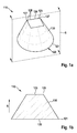
- Abrasive grain 110 shown in a perspective view includes a planar, circular first surface 120 with a first outer contour 121 and a quadratic, ie polygonal, second surface 125 parallel thereto with a second outer contour 126. Between the first surface 120 and the second surface 125, there is a curved one Lateral surface 130 formed. The lines drawn on the lateral surface 130 indicate the curved course of the lateral surface 130; however, they do not represent actual edges of the abrasive grain 110. The abrasive grain 110 extends completely between the two planes defined by the first face 120 and the second face 125.
- the first outer contour 121 has no corner, since the direction of the tangents at the points of the first outer contour 121 is continuous.
- the lack of corners in the first outer contour 121 assists in securely anchoring the abrasive grain 110 in a base binder.
- the second outer contour 126 has four corners 127. Both these corners 127 and the four intermediate edges 128 provide a grinding action.
- the vertical projection of the second surface 125 onto the first surface 120 runs completely in the interior of the first surface 120, as can be clearly seen in FIG. 1b.
- the abrasive grain 110 is particularly stable with respect to the tilting forces occurring during grinding when it rests with the first surface 120 on an abrasive pad, not shown here.
- FIG. 1b shows a side sectional view through the in FIG. 1a section plane S is perpendicular to the first surface 120 and the second surface 125 and through the centers of these two surfaces 120, 125.
- the direction R which extends from the first surface 120 perpendicular to the second surface 125, tapers the abrasive grain 110.
- the abrasive grain 110 can also be placed on the pad with the first face 120 with high probability by means of mechanical scattering. In this orientation, also the corners 127 and the edges 128 away from the pad and thus can cause a grinding effect.
- the section line of the lateral surface 130 with this sectional plane S is rectilinear.
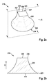
- FIGS. 2a and 2b Another embodiment of the invention is in the FIGS. 2a and 2b shown.
- This abrasive grain 210 also has a flat, circular, first surface 220 with a first outer contour 221 and a quadratic second surface 225 parallel thereto with a second outer contour 226.
- a type of "stand foot" is created with which the abrasive grain 210 can be anchored particularly stably in a base binder.
- abrasive grain 310 has a flat first surface 320 with a first outer contour 321, which is not circular, but also has no corners.
- the parallel opposing second surface 325 has the shape of an irregular pentagon with five corners 327 and five intermediate edges 328.
- This abrasive grain 310 does not taper in the direction R. extending perpendicularly from the first surface 320.
- the abrasive grain 410 also has FIG. 4 a flat first surface 420 having a first outer contour 421 and a second surface 425 extending parallel thereto with a second outer contour 426.
- the second outer contour 426 has four edges 428, 428 ', 428 " Edges 428 'are convexly curved, and the edge 428 "is concavely curved.
- a corner 427 is formed at the point of contact between two edges 428, 428 ', 428 ", namely, at these points the direction of the tangents on the second outer contour 426 is discontinuous.
- the abrasive grains according to the invention can be prepared, for example, by a process described below: First, a dispersion of 200 g of ⁇ -Al 2 O 3 , 0.4 g of MgO, 90 g of water as dispersant and 0.5 g of dispersant is prepared.
- the MgO acts as a nucleating agent.
- a dispersant for example, the product Dolapix CE64 available from Zschimmer & Schwarz, 56108 Lahnstein, Germany can be used.
- the dispersion thus obtained is ground for 30 minutes at 200 revolutions per minute in a planetary ball mill, for example a planetary ball mill PM400, available from Retsch GmbH, 42781 Haan, Germany.
- the ground dispersion is filled into a mold of silicone containing wells in the shape of the desired abrasive grains.
- the volatile component ie the water
- the first surface of the abrasive grain may then be formed from the upper free surface of the dispersion not in contact with the mold.
- the precursor is sintered as bulk material at 1550 ° C for 5 minutes. The disperser is burned out during sintering.
- An abrasive article according to the invention can be prepared, for example, as follows: On a pad of vulcanized fiber having a thickness of 0.8 mm, a phenolic resin dispersion is applied as a base binder precursor in an amount of 120 g / m 2 . Subsequently, 600 g / m 2 of the inventive abrasive grains are applied by means of electrostatic scattering. The base binder precursor is then cured to a base binder. Over the base binder and the abrasive grains is applied a phenolic resin dispersion in an amount of 800 g / m 2 as a coat binder precursor, which is also cured.
Landscapes
- Chemical & Material Sciences (AREA)
- Engineering & Computer Science (AREA)
- Ceramic Engineering (AREA)
- Materials Engineering (AREA)
- Organic Chemistry (AREA)
- Manufacturing & Machinery (AREA)
- Structural Engineering (AREA)
- Inorganic Chemistry (AREA)
- Polishing Bodies And Polishing Tools (AREA)
Abstract
Die Erfindung betrifft einerseits ein Schleifkorn (110) mit einer Oberfläche, die mindestens eine erste Fläche (120) mit einer ersten Aussenkontur (121) und mindestens eine zweite Fläche (125) mit einer zweiten Aussenkontur (126) aufweist. Die erste Aussenkontur (121) enthält keine Ecke, aber die zweite Aussenkontur (126) enthält mindestens eine Ecke (127). Das Schleifkorn (110) kann ein keramisches Material enthalten, insbesondere polykristallines ±-Al 2 O 3 . Zudem sind Gesamtheiten von Schleifkörnern (110), Verfahren zum Herstellen von Schleifkörnern (110), Giessformen, Schleifartikel, Verfahren zum Herstellen von Schleifartikeln und Verfahren zum Schleifen einer Oberfläche offenbart.
Description
- Die vorliegende Erfindung betrifft Schleifkörner mit definierter Form, Gesamtheiten von Schleifkörnern, Verfahren zum Herstellen von Schleifkörnern, Giesswerkzeuge, Schleifartikel mit Schleifkörnern, Verfahren zum Herstellen von Schleifartikeln sowie Verfahren zum Schleifen einer Oberfläche mit einem Schleifartikel.
- Schleifkörner, insbesondere keramische Schleifkörner, mit definierter Form und Grösse sind seit einiger Zeit bekannt.
- Die
US 5,201,916 offenbart unter anderem flache Schleifkörner mit beispielsweise dreieckiger, rechteckiger oder kreisförmiger Form. Diese Schleifkörner werden aus einer Dispersion hergestellt, die in α-Aluminiumoxid konvertierbare Partikel und eine Flüssigkeit mit einer flüchtigen Komponente enthält. Die Dispersion wird in eine Giessform gegossen, die eine ebene Grundfläche und Vertiefungen aufweist, deren Formen komplementär zur gewünschten Formen der Schleifkörner sind. Anschliessend wird ein Teil der flüchtigen Komponente entfernt, so dass ein Vorprodukt mit der gewünschten Form entsteht. Das Vorprodukt wird dann aus der Giessform entnommen, kalziniert und schliesslich gesintert, so dass das fertige Schleifkorn entsteht. - Die mit diesem Verfahren hergestellten Schleifkörner weisen zwei gegenüberliegende Grundflächen auf, die im Wesentlichen die gleiche geometrische Form haben. Den Schleifkörnern wird eine längere Lebensdauer zugewiesen, da von den Schleifkörnern während des Schleifens ständig kleine Stücke abbrechen, so dass sich neue Schneideflächen ergeben. Die Schleifkörner schärfen sich hierdurch selbst. Von Schleifkörnern mit einer Grundfläche in Form eines Dreiecks, insbesondere eines gleichseitigen Dreiecks, wird vermutet, dass sich beim elektrostatischen Streuen etwa ein bis zwei Drittel so orientieren, dass eine Spitze von der Unterlagen weg weist, während sich weitere Schleifkörner so orientieren, dass die Spitze auf die Unterlage zu weist.
- In einem in
EP 615 816 - In der
WO 2009/085841 wird ein weiteres Herstellungsverfahren beschrieben, bei dem das Vorprodukt in der Giessform unter Bedingungen getrocknet wird, die zum Brechen des Vorprodukts führen. Die Bruchstücke weisen zumindest teilweise Oberflächen und Kanten auf, die komplementär zu den entsprechenden Oberflächen und Kanten der Giessform sind und daher den durch die Giessform definierten Winkel aufweisen. Diese Oberflächen und Kanten liefern eine erhöhte Schneidfähigkeit. Die weiteren, durch das Brechen entstandenen Oberflächen und Kanten sind hingegen unregelmässig. - Die
WO 2010/077495 offenbart Schleifkörner, die eine durchgehende oder eine nicht durchgehende Öffnung enthalten oder eine schalenartige Form aufweisen. Auch Herstellungsverfahren für derartige Schleifkörner sind dort beschrieben. Weitere Schleifkörner mit undefinierten Öffnungen sind in derWO 2010/077518 offenbart. DieWO 2010/077491 befasst sich ebenfalls mit Schleifkörnern mit einer schalenartigen Form. - Aus der
WO 2010/077519 sind Schleifkörner bekannt, die zwei gegenüberliegende Hauptflächen und dazwischen verlaufende, zu den Hauptflächen geneigte Seitenflächen aufweisen. Die verschiedenen Seitenflächen eines Schleifkorns können unter verschiedenen Winkeln relativ zu den Hauptflächen geneigt sein. - Das Dokument
WO 2011/068724 zeigt ebenfalls Schleifkörner, welche eine Grundseite und eine Spitze sowie dazwischen verlaufende geneigte Seitenflächen aufweisen. Ähnliche Schleifkornformen sind auch in derWO 2011/109188 beschrieben. - Das Dokument
WO 2010/077509 befasst sich mit Schleifkörnern, die eine Oberfläche mit einer Vielzahl von Furchen aufweisen. Diese Furchen werden mit Hilfe von komplementären Graten an der Unterseite der Giessform erzeugt. - Die
WO 2011/068714 zeigt pyramidenförmige Schleifkörner mit einer parallelogrammförmigen, insbesondere rhombischen, einer drachenförmigen und einer superelliptischen Grundfläche. - Die
WO 2011/139562 offenbart Schleifkörner in Form von Tetraedern und Abwandlungen davon. Beispielsweise können die Seitenflächen konkav oder konvex ausgebildet sein, die Ecken des Tetraeders können abgestumpft sein, oder die Kanten können kurvenförmig sein. - Die in
WO 2012/018903 beschriebenen Schleifkörner enthalten zwei oder mehr plattenförmige Abschnitte, welche unter einem Winkel zueinander angeordnet sind. - Bei dem in
WO 2012/061016 beschriebenen Verfahren wird zunächst ein abrasives Gebilde hergestellt, welches Schleifkornvorprodukte enthält, die über zerbrechliche Stege miteinander verbunden sind. Nach dem Sintern werden die Schleifkörner voneinander getrennt, indem die Stege durchbrochen werden. - Alternativ können Schleifkörner definierter Form auch mit einem Siebdruckverfahren hergestellt werden. Dies beschreibt beispielsweise die
WO 96/12776 - Eine Weiterentwicklung des Siebdruckverfahrens ist in der
WO 2011/087649 offenbart. Bei diesem Verfahren wird die Dispersion mit Hilfe eines Differenzdrucks durch die Öffnungen des Endlosbandes hindurchgedrückt. Bei geeigneter Wahl der Viskosität der Dispersion können mit diesem Verfahren Schleifkörner hergestellt werden, deren Querschnitt sich von einer ersten Hauptseite zu einer zweiten gegenüberliegenden Hauptseite verjüngt. - In der
WO 2012/061033 werden Verfahren zum Herstellen von Schleifkörnern definierter Form mit Hilfe von Laserstrahlung beschrieben. Zudem sind weitere spezielle Formen von Schleifkörnern offenbart. Beispielsweise können die Schleifkörner ein Hauptelement und mindestens drei sich davon erstreckende, stangenförmige Elemente enthalten. Insbesondere kann das Schleifkorn die Form eines Kreuzes, eines Grossbuchstaben "T", eines Sternes oder eines griechischen Kleinbuchstaben "λ" haben. - Allgemein wird davon ausgegangen, dass Schleifkörner mit definierter Form in mehrerlei Hinsicht verbesserte Eigenschaften aufweisen: Haben die Schleifkörner bereits zum Beginn ihrer Herstellung eine definierte Form und Grösse, so entfällt ein anschliessender Sortierschritt, mit dem die Schleifkörner ansonsten in verschiedene Grössenfraktionen aufgeteilt werden müssten. Zudem bleiben die Formen und Grössen auch zwischen verschiedenen Produktionschargen nahezu unverändert, was die Schleifeigenschaften sehr gut reproduzierbar macht. Des Weiteren können die Schleifkörner beispielsweise einen erhöhten Gesamtabtrag leisten, eine längere Lebensdauer haben, eine gesteigerte Oberflächengüte der bearbeiteten Oberfläche erzeugen oder ein besser reproduzierbares Schleifergebnis liefern.
- Dennoch weisen die aus dem Stand der Technik bekannten Schleifkörner eine Reihe von Nachteilen auf. Beispielsweise lassen sich viele der bekannten Schleifkörner nicht sehr platzsparend auf einer Schleifmittel-Unterlage anordnen. Zudem lassen sich viele der bekannten Schleifkörner nicht ausreichend in einem auf einer Schleifmittel-Unterlage aufgetragenen Bindemittel verankern.
- Es ist daher eine Aufgabe der vorliegenden Erfindung, die Nachteile des Standes der Technik zumindest teilweise zu beheben. Insbesondere soll also ein Schleifkorn bereitgestellt werden, welches derart ausgebildet ist, dass sich eine Vielzahl solcher Schleifkörner platzsparender auf einer Schleifmittel-Unterlage anordnen lässt. Zudem sollte das Schleifkorn derart ausgebildet sein, dass es möglichst sicher in einem auf einer Schleifmittel-Unterlage aufgetragenen Grundbinder verankert werden kann. In vorteilhaften Ausgestaltungen sollte das Schleifkorn gleichzeitig derart beschaffen sein, dass eine verbesserte Spanbildung und/oder ein erhöhter Materialabtrag erreicht werden können. Zudem sollte das Schleifkorn in bevorzugten Ausführungsformen derart ausgestaltet sein, dass es sich auch mit Hilfe einer mechanischen Streuung mit möglichst hoher Wahrscheinlichkeit in einer vorteilhaften Orientierung auf einer Unterlage anordnen lässt. Eine vorteilhafte Orientierung liegt beispielsweise dann vor, wenn Ecken und/oder Kanten des Schleifkorns von der Unterlage weg weisen und daher auf eine zu bearbeitende Oberfläche hin weisen.
- Diese Aufgabe wird gelöst durch ein Schleifkorn, welches eine Oberfläche mit mindestens einer ersten Fläche und mindestens einer zweiten Fläche aufweist. Die erste Fläche weist eine erste Aussenkontur auf, welche die erste Fläche begrenzt; die zweite Fläche weist eine zweite Aussenkontur auf, welche die zweite Fläche begrenzt. Erfindungsgemäss enthält die erste Aussenkontur keine Ecke, während die zweite Aussenkontur aber mindestens eine Ecke enthält.
- Hier und im Folgenden wird unter einer Fläche ein zusammenhängender zweidimensionaler Teil der Oberfläche des Schleifkorns verstanden, der aus Punkten besteht, an denen jeweils eine wohldefinierte, gedachte Tangentialebene an das Schleifkorn angelegt werden kann. Eine solche Fläche kann eben oder gewölbt sein, insbesondere konkav gewölbt oder konvex gewölbt. Sie kann auch mindestens einen ebenen Abschnitt und mindestens einen gewölbten Abschnitt aufweisen, wobei diese Abschnitte ohne dazwischen liegende Kante ineinander übergehen.
- Eine Ecke an der zweiten Aussenkontur wird hier und im Folgenden als ein Punkt der zweiten Aussenkontur verstanden, an dem die Richtung der Tangenten an der zweiten Aussenkontur unstetig verläuft. Die erste Aussenkontur enthält erfindungsgemäss keine Ecke. Dies bedeutet also, dass die Richtung der an den Punkten der ersten Aussenkontur anlegbaren Tangenten entlang der gesamten ersten Aussenkontur stetig verläuft. Die erste Aussenkontur kann mindestens einen geradlinigen Abschnitt und/oder mindestens einen gekrümmten Abschnitt enthalten, insbesondere mindestens einen konvex gekrümmten Abschnitt und/oder mindestens einen konkav gekrümmten Abschnitt. An den Punkten, an denen benachbarte Abschnitte einander berühren, soll die Richtung der Tangenten jedoch stetig verlaufen. Beispielsweise kann die erste Fläche kreisförmig oder ellipsenförmig sein.
- Die zweite Aussenkontur enthält mindestens eine wie oben definierte Ecke. Auch die zweite Aussenkontur kann mindestens einen geradlinigen Abschnitt und/oder mindestens einen gekrümmten Abschnitt enthalten, insbesondere mindestens einen konvex gekrümmten Abschnitt und/oder mindestens einen konkav gekrümmten Abschnitt.
- Wenn ein derartiges erfindungsgemässes Schleifkorn mit der ersten Fläche auf einer Schleifmittel-Unterlage aufliegt und insbesondere die erste Fläche in einem dort aufgetragenen Grundbinder eingebettet ist, so ist das Schleifkorn besonders sicher verankert. Es sind dann nämlich dort keine Ecken des Schleifkorns vorhanden, die ansonsten bei der Bearbeitung einer Oberfläche Risse im Grundbinder erzeugen könnten, was zu einem Ausbruch des Schleifkorns führen könnte. Zudem können sich Schleifkörner mit Ecken an der ersten Aussenkontur gegenseitig behindern, wenn sie beim Streuen auf einer Schleifmittel-Unterlage benachbart angeordnet werden. Aufgrund der nicht vorhandenen Ecken an der ersten Aussenkontur können die Schleifkörner somit in vielen Fällen in einer grösseren Dichte auf einer Unterlage platziert werden. Die Ecken der zweiten Aussenkontur, die von der ersten Aussenkontur und daher auch von der Unterlage und dem Grundbinder beabstandet sind und insbesondere davon weg weisen, können hingegen für eine Schleifwirkung sorgen.
- Die erste Fläche ist bevorzugt im Wesentlichen eben. Dies erlaubt eine besonders sichere Fixierung an einer Schleifmittel-Unterlage, wenn das Schleifkorn mit der ersten Fläche auf dieser Unterlage zu liegen kommt.
- Alternativ oder zusätzlich kann die zweite Fläche im Wesentlichen eben sein.
- Zweckmässigerweise liegen die erste Fläche und die zweite Fläche einander gegenüber und sind unter einem Winkel zueinander angeordnet, der kleiner als 30°, bevorzugt kleiner als 20°, weiter bevorzugt kleiner als 10° und besonders bevorzugt 0° ist. Insbesondere wenn die erste Fläche und die zweite Fläche eben sind, ist es vorteilhaft, wenn das Schleifkorn vollständig zwischen den beiden Ebenen verläuft, die durch die erste Fläche und die zweite Fläche definiert werden.
- Wenn ein wie oben genannter Winkel zwischen der ersten Fläche und der zweiten Fläche gebildet ist, insbesondere ein Winkel von 0°, und das Schleifkorn mit seiner ersten Fläche auf einer Schleifmittel-Unterlage aufliegt, so verläuft auch die zweite Fläche unter dem genannten Winkel zu dieser Unterlage, insbesondere also parallel zu der Unterlage. Hierdurch kann eine wohldefinierte Schleifwirkung erzielt werden.
- In geometrisch einfachen Ausführungsformen ist die zweite Fläche durch ein Polygon gebildet. Die Ecken des Polygons bilden dann die Ecken der zweiten Aussenkontur. Sowohl diese Ecken als auch die dazwischen verlaufenden Kanten sorgen für eine verbesserte Spanwirkung und erhöhen den Materialabtrag von einer bearbeiteten Oberfläche. Das Polygon kann konvex sein oder alternativ mindestens eine überstumpfe Ecke aufweisen. Es kann beispielsweise ein Dreieck, insbesondere ein gleichschenkliges oder sogar ein gleichseitiges Dreieck, ein Viereck, insbesondere ein Parallelogramm oder sogar ein Rechteck oder sogar ein Quadrat, ein insbesondere reguläres Fünfeck oder ein insbesondere reguläres Sechseck sein. Regelmässige Polygone sind bevorzugt, da sie eine hohe Symmetrie aufweisen, was zu gleichmässigen Schleifeigenschaften führt.
- In vorteilhaften Ausgestaltungen liegt die senkrechte Projektion der zweiten Fläche auf die erste Fläche vollständig im Inneren der konvexen Hülle der ersten Fläche. Diese konvexe Hülle ist die kleinste konvexe Fläche, die die erste Fläche enthält. Bevorzugt liegt die genannte Projektion sogar im Inneren der ersten Fläche selbst. Hierdurch ist das Schleifkorn besonders stabil gegenüber den beim Schleifen auftretenden Kippkräften, wenn es mit der ersten Fläche auf einer Schleifmittel-Unterlage aufliegt.
- Besonders bevorzugt verjüngt sich das Schleifkorn entlang einer sich von der ersten Fläche senkrecht erstreckenden Richtung. Dies bedeutet also, dass die senkrechte Projektion jeder parallel zur ersten Fläche und in einem ersten Abstand von dieser verlaufenden ersten Querschnittsfläche vollständig im Inneren jeder parallel zur ersten Fläche und in einem zweiten, kleineren Abstand von dieser verlaufenden zweiten Querschnittsfläche liegt. Hierdurch kann eine besonders gute Verankerung in einem auf einer Unterlage aufgetragenen Grundbinder erzielt werden, da das Schleifkorn eine Art von "Standfuss" aufweist. Zudem führt dies dazu, dass das Schleifkorn auch mit Hilfe einer mechanischen Streuung mit hoher Wahrscheinlichkeit mit der ersten Fläche auf der Unterlage zu liegen kommt.
- Zwischen der ersten Fläche und der zweiten Fläche kann eine Mantelfläche gebildet sein. Es ist günstig, wenn die Schnittlinien der Mantelfläche mit mindestens einer senkrecht zur ersten Fläche und senkrecht zur zweiten Fläche verlaufenden Schnittebene zumindest teilweise konkav sind. Hierdurch entsteht in vielen Ausführungsbeispielen ebenfalls eine Art von "Standfuss", der eine verbesserte Verankerung in einem Grundbinder erlaubt. Vorteilhafterweise gilt die genannte Eigenschaft für jede senkrecht zur ersten Fläche und senkrecht zur zweiten Fläche verlaufende Schnittebene. Ebenfalls vorteilhaft ist es, wenn die Schnittlinien vollständig konkav sind. Zudem ist es zweckmässig, wenn die Schnittlinien strikt konkav sind.
- Die Form und die Grösse des Schleifkorns können etwa mit Hilfe eines Mikroskops bestimmt werden. Das erfindungsgemässe Schleifkorn kann eine Grösse im gesamten Grössenbereich aufweisen, der auch für herkömmliche Schleifkörner üblich ist. Üblicherweise führen Schleifkörner mit grösseren Grössen zu einem höheren Materialabtrag von einer bearbeiteten Oberfläche als kleinere Schleifkörner. Beispielsweise kann das Schleifkorn eine Grösse im Bereich von 100 µm bis 2000 µm haben. Diese Grösse kann experimentell mit Hilfe eines Mikroskops bestimmt werden. Sie wird verstanden als der Durchmesser eines Hüllkreises der ersten Fläche, also als der kleinste Durchmesser eines Kreises, der die erste Fläche umschliesst. Weist das Schleifkorn mehrere erste Flächen ohne Ecke auf, so ist die Grösse des Schleifkorns der grösste der Durchmesser all dieser Flächen.
- Bei der oben beschriebenen Form des Schleifkorns handelt es sich um eine Idealisierung. Die Erfindung umfasst jedoch auch Schleifkörner, welche im Rahmen der Herstellungstoleranzen von dieser idealisierten Form abweichen. Mögliche Abweichungen von der idealisierten Form können eine oder mehrere der folgenden Ursachen haben:
- Hohlräume oder Bläschen aufgrund eingeschlossener Luft und/oder anderer Gase in einer Dispersion, aus der die Schleifkörner hergestellt werden;
- fehlende Ecken und/oder Kanten, welche durch ein nicht komplettes Ausfüllen einer Giessform und/oder während eines Entfernens eines Vorprodukts des Schleifkorns aus einer Giessform entstehen;
- eingefallene Seitenflächen und/oder Kanten, die durch ein Schrumpfen während des Entfernens eines Teiles der flüchtigen Komponenten der Dispersion entstehen; insbesondere eingefallene Flächen, die aus der oberen freien, nicht in Kontakt mit der Giessform stehenden Fläche der Dispersion entstehen;
- Abplatzungen, welche durch einen Trocken- und/oder einen Sinterprozess hervorgerufen werden;
- abgebrochene Ecken und/oder Kanten, welche durch einen Transport und/oder während einer Weiterverarbeitung der Schleifkörner als Schüttgut entstehen.
- Die Abweichungen von der Idealisierung müssen nicht zwangsläufig zu nachteiligen Eigenschaften des Schleifkorns führen. Beispielsweise können abgebrochene Ecke und/oder Kanten auch bewirken, dass gegenüber der Idealisierung weitere Schneidkanten entstehen, die die Schleifwirkung sogar positiv beeinflussen können.
- Insbesondere umfasst die Erfindung auch Schleifkörner, deren Form nur im Wesentlichen mit der idealisierten Form übereinstimmt. Beispielsweise werden die erste oder die zweite Fläche als im Wesentlichen eben verstanden, wenn sie gewölbt sind und Krümmungsradien aufweisen, die mindestens das Doppelte, bevorzugt mindestens das Fünffache, besonders bevorzugt mindestens das Zehnfache der oben definierten Grösse des Schleifkorns betragen. Des Weiteren wird ein Punkt der zweiten Aussenkontur als Ecke angesehen, wenn dort eigentlich eine Krümmung vorliegt, deren Krümmung jedoch höchstens 10 %, bevorzugt höchstens 5 %, besonders bevorzugt höchstens 2 % der Grösse des Schleifkorns beträgt. Ebenso werden Abschnitte der ersten oder der zweiten Aussenkontur als geradlinig angesehen, wenn sie zumindest teilweise oder sogar vollständig kurvenförmig sind und einen Krümmungsradius aufweisen, der mindestens das Doppelte, bevorzugt mindestens das Fünffache, besonders bevorzugt mindestens das Zehnfache der Grösse des Schleifkorns beträgt. Insbesondere wird auch eine Aussenkontur aus Polygon angesehen, wenn sie aus solchen im Wesentlichen geradlinigen Abschnitten und Ecken zusammengesetzt ist.
- Bevorzugt weist das Schleifkorn aber eine wie oben beschriebene idealisierte Form auf.
- Das Schleifkorn kann beispielsweise ein keramisches Material, insbesondere ein polykristallines keramisches Material, enthalten oder daraus bestehen. Bevorzugt enthält das Schleifkorn Aluminiumoxid, besonders bevorzugt α-Al2O3.
- Alternativ oder zusätzlich kann das Schleifkorn auch noch mindestens ein weiteres Metalloxid enthalten, wie etwa Natriumoxid, Magnesiumoxid, Eisenoxid, Siliziumoxid, Kalziumoxid, Zirkonoxid, Yttriumoxid, Zinkoxid, Kobaltoxid, Nickeloxid, Hafniumoxid, Chromoxid, Praseodymoxid, Samariumoxid, Ytterbiumoxid, Neodymoxid, Lanthanoxid, Gadoliniumoxid, Ceroxid, Dysprosiumoxid, Erbiumoxid, Lutetiumoxid, Titanoxid, Manganoxid oder beliebige Kombinationen davon.
- Viele dieser Metalloxide stammen von Verunreinigungen in den Ausgangsrohstoffen, wie beispielsweise in Aluminiumoxid. Bei ausreichend geringen Anteilen im Schleifkorn haben solche Verunreinigungen jedoch keinen negativen Einfluss auf die Herstellung und die Anwendung des Schleifkorns. Einige der genannten Verunreinigungen können sogar einen positiven Effekt auf das Schleifkorn haben.
- Anteile von Zirkonoxid oder Yttriumoxid können beispielsweise von Mahlkugeln stammen, die in einem Mahlschritt bei der Herstellung der Schleifkörner verwendet werden können. Anteile von Eisenoxid können aus einem Mahlbehälter stammen, der bei einem solchen Mahlschritt verwendet wird.
- Ebenfalls alternativ oder zusätzlich kann das Schleifkorn weitere Hartstoffe enthalten, wie beispielsweise Siliziumkarbid.
- Weiterhin kann das Schleifkorn mindestens ein Zersetzungsprodukt eines unten näher beschriebenen Dispergators enthalten, der bei der Herstellung der Schleifkörner verwendet wurde. Ferner kann das Schleifkorn mindestens einen Keimbildner oder dessen Zersetzungsprodukt enthalten, welches bei der Herstellung der Schleifkörner verwendet wurde. Bei dem Keimbildner kann es sich beispielsweise um das oben bereits erwähnte Magnesiumoxid handeln. Zudem kann das Schleifkorn auch mindestens einen der weiteren in der
EP 615 816 Al - Die genannten Inhaltsstoffe können mit Hilfe von an sich bekannten chemischen Analyseverfahren bestimmt werden.
- Das Schleifkorn kann ein Gefüge mit einer oder mehreren verschiedenen Phasen enthalten oder daraus bestehen. Dabei kann eine erste Phase aus Aluminiumoxid, besonders bevorzugt aus α-Al2O3 bestehen. Eine zweite Phase kann aus einem oder mehreren der oben genannten weiteren Metalloxide und/oder weiteren Hartstoffe bestehen.
- Der Anteil an Aluminiumoxid, insbesondere an α-Al2O3, im Schleifkorn kann beispielsweise mindestens 25 Gew.-%, bevorzugt mindestens 50 Gew.-%, weiter bevorzugt mindestens 70 Gew.-%, besonders bevorzugt mindestens 95 Gew.-% betragen.
- Das Schleifkorn kann eine Beschichtung aufweisen, welche nur einen Teil der Oberfläche bedeckt, insbesondere nur eine oder mehrere Kanten und/oder nur einen von mehreren flächigen Bereichen der Oberfläche. Bei der Beschichtung kann es sich etwa um eine ferromagnetische oder eine paramagnetische Beschichtung handeln. Eine solche teilweise Beschichtung der Oberfläche mit einem ferromagnetischen oder einem paramagnetischen Material ermöglicht es, das Schleifkorn in einem während des Streuens angelegten Magnetfeld in einer vorgegebenen Richtung auszurichten. Alternativ kann es sich auch um eine Beschichtung aus einem Material mit einer erhöhten Wärmeleitfähigkeit handeln oder um eine Beschichtung, welche eine erhöhte Adhäsion des Schleifkorns auf der Schleifmittel-Unterlage ermöglicht.
- Ein weiterer Aspekt der Erfindung betrifft eine Gesamtheit von Schleifkörnern. Unter einer Gesamtheit von Schleifkörnern wird hier und im Folgenden eine zusammengehörige Ansammlung von Schleifkörnern verstanden. Beispielsweise kann es sich dabei um eine Ansammlung von Schleifkörnern handeln, die in einem Gebinde enthalten und so gelagert und/oder transportiert werden, beispielsweise in einem Sack.
- Eine solche Ansammlung von Schleifkörner kann zur Herstellung eines Schleifartikels verwendet werden. Als Gesamtheit von Schleifkörnern wird auch die Gesamtheit aller in einem Schleifartikel vorhandenen Schleifkörner angesehen.
- Bevorzugt enthält die Gesamtheit von Schleifkörnern mindestens 20 Gew.-%, bevorzugt mindestens 50 Gew.-%, besonders bevorzugt mindestens 90 Gew.-% erfindungsgemässe Schleifkörner, so wie sie oben beschrieben wurden. Die übrigen in der Gesamtheit enthalten Schleifkörner können ebenfalls eine definierte Form aufweisen, welche jedoch von der erfindungsgemässen Form abweicht, oder sie können keine definierte Form aufweisen, da es sich beispielsweise um gebrochene Schleifkörner handelt. Diese übrigen in der Gesamtheit enthalten Schleifkörner werden auch als "Stützkörner" bezeichnet.
- Es ist denkbar und liegt im Rahmen der Erfindung, dass die in der Gesamtheit enthaltenen erfindungsgemässen Schleifkörner voneinander verschieden ausgebildet sind. So kann die Gesamtheit von Schleifkörnern beispielsweise einen ersten Anteil von Schleifkörnern einer ersten erfindungsgemässen Ausführungsform enthalten sowie einen zweiten Anteil von Schleifkörnern einer zweiten erfindungsgemässen Ausführungsform, die von der ersten erfindungsgemässen Ausführungsform verschieden ist. Insbesondere können sich die Schleifkörner der ersten erfindungsgemässen Ausführungsform in ihrer Grösse und/oder in ihrer Form von den Schleifkörnern der zweiten erfindungsgemässen Ausführungsform unterscheiden.
- Die Gesamtheit von Schleifkörnern kann ausschliesslich aus identischen erfindungsgemässen Schleifkörnern bestehen; insbesondere hat die Gesamtheit dann eine punktförmige Grössenverteilung.
- Die Gesamtheit von Schleifkörnern kann im Wesentlichen eine Grössenverteilung aufweisen, die einem in der Schleifmittelindustrie üblichen Grössenstandard entspricht, beispielsweise dem American National Standards Institute (ANSI), den Standards der Federation of European Producers of Abrasives (FEPA) oder dem Japanese Industrial Standard (JIS). Beispielsweise kann die Gesamtheit der Schleifkörner im Wesentlichen eine Körnung P12, P16, P20, P24, P30, P36, P40, P50, P60, P80, P100, P120, P150, P180, P220, P240, P280, P320, P360, P400, P500, P600, P800, P1000, P1200, P1500, P2000, P2500, P3000 oder P5000 gemäss dem FEPA-Standard aufweisen. Dabei bedeutet eine Grössenverteilung "im Wesentlichen", dass zumindest 90 Gew.-%, bevorzugt mindestens 95 Gew.-%, weiter bevorzugt mindestens 99 Gew.-% und besonders bevorzugt sämtliche Schleifkörner der Gesamtheit von Schleifkörnern diesen Standard erfüllen.
- Wie oben bereits beschrieben wurde, ist es auch denkbar, dass die Gesamtheit mindestens zwei verschiedene Anteile erfindungsgemässer Schleifkörner und/oder mindestens einen Anteil nicht erfindungsgemässer Schleifkörner enthält. Jeder dieser Anteile kann für sich eine Grössenverteilung aufweisen, die jeweils einem der oben genannten, in der Schleifmittelindustrie üblichen Grössenstandards entspricht.
- Ein erfindungsgemässes Schleifkorn oder eine erfindungsgemässe Gesamtheit von Schleifkörnern kann beispielsweise mit dem folgenden, aus
US 5,201,916 bekannten Verfahren hergestellt werden: - a) Herstellung oder Bereitstellung einer Dispersion, enthaltend α-Aluminiumoxid-Partikel und/oder Partikel, welche in α-Aluminiumoxid umwandelbar sind, sowie mindestens ein flüchtiges Dispersionsmittel, bevorzugt Wasser;
- b) Einfüllen der Dispersion in mindestens eine Vertiefung einer Giessform;
- c) optional Abrakeln einer Oberseite der Giessform, um zumindest einen Teil der Dispersion zu entfernen, der über die Oberseite der Giessform übersteht;
- d) Entfernen eines Teiles der flüchtigen Komponenten der Dispersion, so dass mindestens ein Schleifkorn-Vorprodukt entsteht;
- e) Entfernen des Schleifkorn-Vorprodukts aus der Giessform;
- f) optional Kalzinieren des Schleifkorn-Vorprodukts;
- g) Sintern des Schleifkorn-Vorprodukts, um mindestens ein Schleifkorn zu erhalten.
- Vor und/oder während der Herstellung der Dispersion im Schritt a) können die Rohstoffe, insbesondere α-Aluminiumoxid-Partikel und/oder Partikel, welche in α-Aluminiumoxid umwandelbar sind, gemahlen werden. Dies kann beispielsweise mit Hilfe einer Kugelmühle erfolgen, insbesondere mit Hilfe einer Planetenkugelmühle.
- Die Dispersion kann mindestens einen Dispergator enthalten. Ein solcher Dispergator erleichtert die Bildung der Dispersion und erhöht ihre Stabilität, indem er beispielsweise Schichten um die einzelnen Körner herum bildet, die das Zusammenklumpen verhindern. Bei dem Dispergator kann es sich beispielsweise um ein Polymer handeln. In der Regel zersetzt sich der Dispergator spätestens während des Sinterns im Schritt g).
- Zum Herstellen der erfindungsgemässen Schleifkörner kann ein Giesswerkzeug verwendet werden, wobei das Giesswerkzeug mindestens eine Giessform umfasst, die mindestens eine Vertiefung mit einer jeweiligen Oberfläche aufweist, wobei die Oberfläche komplementär zur Form zumindest eines Teils der Oberfläche des Schleifkorns ist.
- Bevorzugt befindet sich eine Vielzahl von Vertiefungen in der Giessform, sodass mit einem Giessvorgang eine Vielzahl von Schleifkörnern gegossen werden kann.
- In einer Weiterentwicklung des aus
US 5,201,916 bekannten Verfahrens kann die oben genannte Giessform nur ein Teil eines mehrteiligen Giesswerkzeugs sein, welches zusätzlich mindestens ein Formelement, insbesondere eine weitere Giessform oder ein Stempelelement, umfasst, mit welchem ergänzend zu der in der ersten Giessform geformten Oberfläche zumindest ein Teil der restlichen Oberfläche des Schleifkorns formbar ist. Dies ist insbesondere dann sinnvoll, wenn das herzustellende Schleifkorn Hinterschneidungen aufweist. - Beispielsweise können Stempelelemente vorgesehen sein, die in die gefüllten Vertiefungen der ersten Giessform geführt werden. Alternativ ist es auch denkbar, dass im optionalen Schritt c) nicht die gesamte über die Oberseite der Giessform überstehende Dispersion abgerakelt wird, sondern stattdessen eine Schicht geeigneter Dicke über der Oberseite der Giessform stehen gelassen wird. Hierfür sollte die Dispersion im Schritt c) ausreichend formstabil sein. Beispielsweise kann im Schritt b) eine bereits ausreichend formstabile Dispersion eingefüllt werden oder die Dispersion zwischen den Schritten b) und c) in einen ausreichend formstabilen Zustand überführt werden. Die Stempelelemente müssen bei dieser Variante nicht zwingend in die Vertiefung eindringen; stattdessen kann mit Hilfe der Stempelelemente eine Formgebung in dem überstehenden Teil der Dispersion erfolgen.
- Bevorzugt schliessen die Stempelelemente die Vertiefungen der Giessform nicht vollständig ab, so dass die flüchtige Komponente der Dispersion entweichen kann.
- Kompliziertere Formen von Schleifkörnern sind in zusammensetzbaren Giessformen, ähnlich wie im Spritzgussverfahren, formbar. Dazu weist mindestens eine Giessform mindestens eine Einfüllöffnung auf, durch welche die Dispersion in die Vertiefungen gelangen kann.
- Die Giessform und/oder das Stempelelement kann beispielsweise Silikon enthalten oder daraus bestehen. Die Vertiefungen können eine offene Deckfläche aufweisen, durch die die Dispersion eingefüllt werden kann. Die Vertiefungen der Giessform weisen jeweils eine Oberfläche auf, deren Form komplementär zur Form zumindest eines Teils der Oberfläche des gewünschten Schleifkorns ist. Bevorzugt weisen die Vertiefungen der Giessform jeweils eine Oberfläche auf, deren Form komplementär zur Form des Teils der Oberfläche des Schleifkorns ist, der nicht die erste Fläche des Schleifkorns bildet oder der nicht die zweite Fläche des Schleifkorns bildet. Die erste Fläche bzw. die zweite Fläche kann dann aus der oberen freien, nicht in Kontakt mit der Giessform stehenden Fläche der Dispersion entstehen. Aufgrund eines möglichen Schrumpfens der Dispersion während des Schritts d) ist es möglich, dass die erste Fläche bzw. die zweite Fläche nicht vollständig eben ist, sondern eine geringfügige Wölbung aufweist.
- Das im Schritt d) entstehende Vorprodukt sollte bevorzugt mechanisch stabil genug sein, um in den nachfolgenden Schritten als Schüttgut weiterverarbeitet werden zu können. Das optionale Kalzinieren in Schritt f) ist insbesondere dann vorteilhaft oder sogar erforderlich, wenn die Dispersion mehrere verschiedene Rohstoffe enthält und eine Phasenumwandlung erforderlich ist.
- Noch ein Aspekt der Erfindung betrifft einen Schleifartikel, welcher eine wie oben beschriebene Gesamtheit von Schleifkörnern enthält. Insbesondere können also mindestens 20 Gew.-%, bevorzugt mindestens 50 Gew.-%, besonders bevorzugt mindestens 90 Gew.-% aller Schleifkörner des Schleifartikels als erfindungsgemässe Schleifkörner ausgebildet sein, so wie sie oben beschrieben wurden. Die übrigen Schleifkörner können ebenfalls eine definierte Form aufweisen, welche jedoch von der erfindungsgemässen Form abweicht, oder sie können keine definierte Form aufweisen.
- Bei dem Schleifartikel kann es sich beispielsweise um einen beschichteten Schleifartikel (englisch: "coated abrasive"), einen Vliesschleifartikel, um einen gebundenen Schleifartikel (englisch: "bonded abrasive") oder um eine Schleifbürste handeln.
- Ein beschichteter Schleifartikel enthält eine insbesondere flexible Unterlage, wie beispielsweise Papier, Vulkanfiber, eine Folie, ein textiles Material, einen Schaumstoff oder mehrschichtige Kombinationen davon. Die Schleifkörner können mit Hilfe eines Grundbinders (englisch: "make coat") an der Unterlage befestigt sein. Der Grundbinder und die Schleifkörner können mit einem Deckbinder (englisch: "size coat") überdeckt sein. Optional kann oberhalb des genannten Deckbinders auch noch ein zweiter Deckbinder vorhanden sein (englisch: "supersize coat").
- Als Grundbinder, Deckbinder und zweiter Deckbinder können sämtliche an sich bekannte Bindemittel eingesetzt werden, beispielsweise aus Kunstharz, wie etwa einem Phenolharz, einem Epoxid, einem Harnstoffharz, einem Melaminharz oder einem ungesättigten Polyesterharz. Der Deckbinder und/oder der zweite Deckbinder können zudem weitere übliche Wirkstoffe und/oder Füllstoffe enthalten.
- Der Schleifartikel kann in unterschiedlichen Konfektionsformen vorliegen, beispielsweise als Schleifscheibe oder als Schleifband.
- Die Erfindung umfasst auch ein Verfahren zum Herstellen eines wie oben beschriebenen erfindungsgemässen Schleifartikels. Das Verfahren enthält einen Schritt, in dem eine Gesamtheit von Schleifkörnern an und/oder in einem Substrat fixiert wird, insbesondere mittels eines Bindemittels. Bei dem Substrat kann es sich etwa um eine insbesondere flexible Unterlage eines beschichteten Schleifartikels, um ein Vliesmaterial eines Vliesschleifmittels, um eine Matrix eines gebundenen Schleifmittels oder um Borsten einer Schleifbürste handeln. Im Falle eines beschichteten Schleifartikels kann das Auftragen des Grundbinders und/oder der Schleifkörner und/oder des Deckbinders und/oder des zweiten Deckbinders mit einer an sich bekannten Methode erfolgen. Beispielsweise können die Schleifkörner elektrostatisch oder mechanisch (d. h. gravimetrisch) aufgetragen werden. Insbesondere bei den oben beschriebenen vorteilhaften Ausführungsformen wird auch beim mechanischen Streuen ein grosser Anteil der Schleifkörner so orientiert, dass die erste Fläche auf einer Unterlage zu liegen kommt. Auf eine aufwändigere elektrostatische Streuung kann also verzichtet werden.
- Ferner richtet sich die Erfindung auch auf ein Verfahren zum Schleifen einer Oberfläche mit einem wie oben beschriebenen Schleifartikel. Bei der Oberfläche kann es sich insbesondere um eine lackierte Oberfläche handeln. Im Falle einer lackierten Oberfläche sind Schleifkörner mit Grössen von 500 µm oder weniger besonders geeignet.
- Im Folgenden wird die Erfindung mit Hilfe mehrerer Ausführungsbeispiele und Zeichnungen näher erläutert. Dabei zeigen
-
Figuren 1a und b: eine erste Ausführungsform eines erfindungsgemässen Schleifkorns in zwei Ansichten; -
Figuren 2a und b: eine zweite Ausführungsform eines erfindungsgemässen Schleifkorns in zwei Ansichten; -
Figur 3 : eine dritte Ausführungsform eines erfindungsgemässen Schleifkorns; -
Figur 4 : eine vierte Ausführungsform eines erfindungsgemässen Schleifkorns. - Das in
Figur 1a in einer perspektivischen Ansicht dargestellte Schleifkorn 110 enthält eine ebene, kreisförmige erste Fläche 120 mit einer ersten Aussenkontur 121 und eine dazu parallele quadratische, also polygonale zweite Fläche 125 mit einer zweiten Aussenkontur 126. Zwischen der ersten Fläche 120 und der zweiten Fläche 125 ist eine gewölbte Mantelfläche 130 gebildet. Die auf der Mantelfläche 130 gezeichneten Linien deuten den gewölbten Verlauf der Mantelfläche 130 an; sie stellen jedoch keine tatsächlichen Kanten des Schleifkorns 110 dar. Das Schleifkorn 110 verläuft vollständig zwischen den beiden Ebenen, die durch die erste Fläche 120 und die zweite Fläche 125 definiert werden. - Die erste Aussenkontur 121 weist keine Ecke auf, da die Richtung der Tangenten an den Punkten der ersten Aussenkontur 121 stetig verläuft. Das Fehlen von Ecken in der ersten Aussenkontur 121 trägt zur sicheren Verankerung des Schleifkorns 110 in einem Grundbinder bei. Im Gegensatz zur ersten Aussenkontur 121 weist die zweite Aussenkontur 126 vier Ecken 127 auf. Sowohl diese Ecken 127 als auch die vier dazwischen verlaufenden Kanten 128 sorgen für eine Schleifwirkung.
- Die senkrechte Projektion der zweiten Fläche 125 auf die erste Fläche 120 verläuft vollständig im Inneren der ersten Fläche 120, wie auch in Figur lb gut zu erkennen ist. Hierdurch ist das Schleifkorn 110 besonders stabil gegenüber den beim Schleifen auftretenden Kippkräften, wenn es mit der ersten Fläche 120 auf einer hier nicht dargestellten Schleifmittel-Unterlage aufliegt.
-
Figur 1b zeigt eine seitliche Schnittansicht durch die inFigur 1a dargestellte Schnittebene S. Diese Schnittebene S verläuft senkrecht zur ersten Fläche 120 und zur zweiten Fläche 125 und durch die Mittelpunkte dieser beiden Flächen 120, 125. Entlang der Richtung R, die sich von der ersten Fläche 120 senkrecht zur zweiten Fläche 125 erstreckt, verjüngt sich das Schleifkorn 110. Hierdurch kann eine besonders gute Verankerung in einem auf einer Unterlage aufgetragenen Grundbinder erzielt werden. Zudem kann das Schleifkorn 110 auch mit Hilfe einer mechanischen Streuung mit hoher Wahrscheinlichkeit mit der ersten Fläche 120 auf der Unterlage platziert werden. In dieser Orientierung weisen auch die Ecken 127 und die Kanten 128 von der Unterlage weg und können somit eine Schleifwirkung hervorrufen. Die Schnittlinie der Mantelfläche 130 mit dieser Schnittebene S verläuft geradlinig. - Eine weitere erfindungsgemässe Ausführungsform ist in den
Figuren 2a und 2b dargestellt. Auch dieses Schleifkorn 210 weist eine ebene kreisförmige, erste Fläche 220 mit einer ersten Aussenkontur 221 und eine dazu parallele quadratische zweite Fläche 225 mit einer zweiten Aussenkontur 226 auf. Im Gegensatz zum Schleifkorn 110 gemäss denFiguren 1a und 1b ist die Schnittlinie der Mantelfläche 230 des Schleifkorns 210 mit einer Schnittebene S konvex, wie inFigur 2b zu sehen ist. Durch diese Konvexität entsteht im Bereich der ersten Fläche 220 eine Art von "Standfuss", mit dem das Schleifkorn 210 besonders stabil in einem Grundbinder verankert werden kann. - Das in
Figur 3 gezeigte Schleifkorn 310 hat eine ebene erste Fläche 320 mit einer ersten Aussenkontur 321, die zwar nicht kreisförmig ist, aber ebenso keine Ecken aufweist. Die parallel dazu verlaufende gegenüberliegende zweite Fläche 325 hat die Form eines unregelmässigen Fünfecks mit fünf Ecken 327 und fünf dazwischen verlaufenden Kanten 328. Dieses Schleifkorn 310 verjüngt sich nicht in der sich von der ersten Fläche 320 senkrecht erstreckenden Richtung R. - Schliesslich hat auch das Schleifkorn 410 gemäss
Figur 4 eine ebene erste Fläche 420 mit einer ersten Aussenkontur 421 und eine parallel dazu verlaufende zweite Fläche 425 mit einer zweiten Aussenkontur 426. Die zweite Aussenkontur 426 weist vier Kanten 428, 428', 428" auf. Von diesen Kanten ist die Kante 428 geradlinig; die Kanten 428' sind konvex gekrümmt; die Kante 428" ist konkav gekrümmt. Jeweils am Berührungspunkt zweier Kanten 428, 428', 428" ist eine Ecken 427 gebildet; an diesen Punkten verläuft nämlich die Richtung der Tangenten an der zweiten Aussenkontur 426 unstetig. - Die erfindungsgemässen Schleifkörner können beispielsweise mit einem im Folgenden beschriebenen Verfahren hergestellt werden: Zunächst wird eine Dispersion aus 200 g α-Al2O3, 0,4 g MgO, 90 g Wasser als Dispersionsmittel und 0,5 g Dispergator hergestellt. Das MgO fungiert dabei als Keimbildner. Als Dispergator kann beispielsweise das Produkt Dolapix CE64, erhältlich von Zschimmer & Schwarz, 56108 Lahnstein, Deutschland eingesetzt werden. Die somit erhaltene Dispersion wird für 30 Minuten bei 200 Umdrehungen pro Minute in einer Planetenkugelmühle gemahlen, beispielsweise einer Planetenkugelmühle PM400, erhältlich von der Retsch GmbH, 42781 Haan, Deutschland. Anschliessend wird die gemahlene Dispersion in eine Giessform aus Silikon eingefüllt, die Vertiefungen in der Form der gewünschten Schleifkörner enthält. Daraufhin wird die flüchtige Komponente, also das Wasser, aus der Dispersion entfernt. Hierdurch entsteht ein Schleifkorn-Vorprodukt, welches aus der Giessform entfernt wird. Die erste Fläche des Schleifkorns kann dann aus der oberen freien, nicht in Kontakt mit der Giessform stehenden Fläche der Dispersion entstehen. In einem abschliessenden Schritt wird das Vorprodukt als Schüttgut bei 1550 °C für 5 Minuten gesintert. Der Dispergator wird beim Sintern herausgebrannt.
- Ein erfindungsgemässer Schleifartikel kann beispielsweise wie folgt hergestellt werden: Auf einer Unterlage aus Vulkanfiber mit einer Dicke von 0,8 mm wird eine Phenolharz-Dispersion als Grundbinder-Vorläufer in einer Menge von 120 g/m2 aufgetragen. Anschliessend werden 600 g/m2 der erfindungsgemässen Schleifkörner mittels elektrostatischer Streuung aufgetragen. Daraufhin wird der Grundbinder-Vorläufer zu einem Grundbinder gehärtet. Über dem Grundbinder und den Schleifkörnern wird eine Phenolharz-Dispersion in einer Menge von 800 g/m2 als Deckbinder-Vorläufer aufgetragen, welche ebenfalls gehärtet wird.
Claims (15)
- Schleifkorn (110; 210; 310; 410), aufweisend eine Oberfläche mit mindestens einer ersten Fläche (120; 220; 320; 420) mit einer ersten Aussenkontur (121; 221; 321; 421) und mindestens einer zweiten Fläche (125; 225; 325; 425) mit einer zweiten Aussenkontur (126; 226; 326; 426),
dadurch gekennzeichnet, dass
die erste Aussenkontur (121; 221; 321; 421) keine Ecke enthält und die zweite Aussenkontur (126; 226; 326; 426) mindestens eine Ecke (127; 227; 327; 427) enthält. - Schleifkorn (110; 210; 310; 410) gemäss Anspruch 1,
dadurch gekennzeichnet, dass
die erste Fläche (120; 220; 320; 420) im Wesentlichen eben ist. - Schleifkorn (110; 210; 310; 410) gemäss einem der vorangehenden Ansprüche,
dadurch gekennzeichnet, dass
die erste Fläche (120; 220; 320; 420) und die zweite Fläche (125; 225; 325; 425) einander gegenüberliegen und unter einem Winkel zueinander angeordnet sind, der kleiner als 30°, bevorzugt kleiner als 20°, weiter bevorzugt kleiner als 10° und besonders bevorzugt 0° ist. - Schleifkorn (110; 210; 310; 410) gemäss einem der vorangehenden Ansprüche,
dadurch gekennzeichnet, dass
das Schleifkorn (110; 210; 310; 410) vollständig zwischen den beiden Ebenen verläuft, die durch die erste Fläche (120; 220; 320; 420) und die zweite Fläche (125; 225; 325; 425) definiert werden. - Schleifkorn (110; 210; 310) gemäss einem der vorangehenden Ansprüche,
dadurch gekennzeichnet, dass
die zweite Fläche (125; 225; 325) durch ein Polygon gebildet ist. - Schleifkorn (110; 210) gemäss einem der vorangehenden Ansprüche,
dadurch gekennzeichnet, dass
die senkrechte Projektion der zweiten Fläche (125; 225) auf die erste Fläche (120; 220) vollständig im Inneren der konvexen Hülle der ersten Fläche (120; 220), insbesondere im Inneren der ersten Fläche (120; 220) liegt. - Schleifkorn (110; 210) gemäss Anspruch 6,
dadurch gekennzeichnet, dass
sich das Schleifkorn (110; 210) entlang einer sich von der ersten Fläche (120; 220) senkrecht erstreckenden Richtung (R) verjüngt. - Schleifkorn (210) gemäss einem der vorangehenden Ansprüche,
dadurch gekennzeichnet, dass
zwischen der ersten Fläche (220) und der zweiten Fläche (225) eine Mantelfläche (230) gebildet ist, wobei die Schnittlinien der Mantelfläche (230) mit mindestens einer senkrecht zur ersten Fläche (220) und senkrecht zur zweiten Fläche (225) verlaufenden Schnittebene (S), insbesondere mit jeder solchen Schnittebene (S), zumindest teilweise, bevorzugt vollständig, konkav, insbesondere strikt konkav sind. - Schleifkorn (110; 210; 310; 410) gemäss einem der vorangehenden Ansprüche,
dadurch gekennzeichnet, dass
es ein keramisches Material, insbesondere ein polykristallines keramisches Material, enthält oder daraus besteht, bevorzugt Aluminiumoxid, besonders bevorzugt α-Al2O3. - Gesamtheit von Schleifkörnern (110; 210; 310; 410),
dadurch gekennzeichnet, dass
sie mindestens 20 Gew.-%, bevorzugt mindestens 50 Gew.-%, besonders bevorzugt mindestens 90 Gew.-% Schleifkörner (110; 210; 310; 410) nach einem der vorangehenden Ansprüche enthält. - Verfahren zum Herstellen mindestens eines Schleifkorns (110; 210; 310; 410) oder einer Gesamtheit von Schleifkörnern (110; 210; 310; 410) gemäss einem der vorangehenden Ansprüche,
gekennzeichnet durch die folgenden Schritte:a) Herstellung oder Bereitstellung einer Dispersion, enthaltend α-Aluminiumoxid-Partikel und/oder Partikel, welche in α-Aluminiumoxid umwandelbar sind, sowie mindestens ein flüchtiges Dispersionsmittel, bevorzugt Wasser;b) Einfüllen der Dispersion in mindestens eine Vertiefung einer Giessform;c) optional Abrakeln einer Oberseite der Giessform, um zumindest einen Teil der Dispersion zu entfernen, der über die Oberseite der Giessform übersteht;d) Entfernen eines Teiles der flüchtigen Komponenten der Dispersion, so dass mindestens ein Schleifkorn-Vorprodukt entsteht;e) Entfernen des Schleifkorn-Vorprodukts aus der Giessform;f) optional Kalzinieren des Schleifkorn-Vorprodukts;g) Sintern des Schleifkorn-Vorprodukts, um mindestens ein Schleifkorn (110; 210; 310; 410) zu erhalten. - Giesswerkzeug zum Herstellen mindestens eines Schleifkorns (110; 210; 310; 410) nach einem der Ansprüche 1 bis 9, wobei das Giesswerkzeug mindestens eine Giessform umfasst, die mindestens eine Vertiefung, bevorzugt eine Vielzahl von Vertiefungen, mit einer jeweiligen Oberfläche aufweist, wobei die Oberfläche komplementär zur Form zumindest eines Teils der Oberfläche des Schleifkorns (110; 210; 310; 410) ist.
- Schleifartikel, enthaltend eine Gesamtheit von Schleifkörnern (110; 210; 310; 410) gemäss Anspruch 10.
- Verfahren zum Herstellen eines Schleifartikels gemäss Anspruch 13, enthaltend einen Schritt, in dem eine Gesamtheit von Schleifkörnern (110; 210; 310; 410) gemäss Anspruch 10 an und/oder in einem Substrat fixiert wird, insbesondere mittels eines Bindemittels.
- Verfahren zum Schleifen einer Oberfläche, insbesondere einer lackierten Oberfläche, mit einem Schleifartikel gemäss Anspruch 13.
Priority Applications (8)
| Application Number | Priority Date | Filing Date | Title |
|---|---|---|---|
| EP12178931.7A EP2692814A1 (de) | 2012-08-02 | 2012-08-02 | Schleifkorn, enthaltend eine erste Fläche ohne Ecke und zweite Fläche mit Ecke |
| PCT/EP2013/066105 WO2014020075A1 (de) | 2012-08-02 | 2013-07-31 | Schleifkorn, enthaltend eine erste fläche ohne ecke und zweite fläche mit ecke |
| US14/417,886 US9771505B2 (en) | 2012-08-02 | 2013-07-31 | Abrasive grain containing a first face without vertices and a second face with vertices |
| CN201710427599.0A CN107234550A (zh) | 2012-08-02 | 2013-07-31 | 包含不具有角的第一面以及具有角的第二面的磨粒 |
| CN201380041116.3A CN104508073B (zh) | 2012-08-02 | 2013-07-31 | 包含不具有角的第一面以及具有角的第二面的磨粒 |
| EP16199983.4A EP3170879B1 (de) | 2012-08-02 | 2013-07-31 | Schleifkorn mit einer oberfläche, die mindestens eine grundfläche mit einer aussenkontur enthält, die mindestens sieben ecken aufweist |
| EP13744534.2A EP2880117B1 (de) | 2012-08-02 | 2013-07-31 | Schleifkorn, enthaltend eine erste fläche ohne ecke und zweite fläche mit ecke |
| US15/672,731 US10557068B2 (en) | 2012-08-02 | 2017-08-09 | Abrasive grain with main surfaces and subsidiary surfaces |
Applications Claiming Priority (1)
| Application Number | Priority Date | Filing Date | Title |
|---|---|---|---|
| EP12178931.7A EP2692814A1 (de) | 2012-08-02 | 2012-08-02 | Schleifkorn, enthaltend eine erste Fläche ohne Ecke und zweite Fläche mit Ecke |
Publications (1)
| Publication Number | Publication Date |
|---|---|
| EP2692814A1 true EP2692814A1 (de) | 2014-02-05 |
Family
ID=46642383
Family Applications (1)
| Application Number | Title | Priority Date | Filing Date |
|---|---|---|---|
| EP12178931.7A Withdrawn EP2692814A1 (de) | 2012-08-02 | 2012-08-02 | Schleifkorn, enthaltend eine erste Fläche ohne Ecke und zweite Fläche mit Ecke |
Country Status (1)
| Country | Link |
|---|---|
| EP (1) | EP2692814A1 (de) |
Cited By (41)
| Publication number | Priority date | Publication date | Assignee | Title |
|---|---|---|---|---|
| US8840696B2 (en) | 2012-01-10 | 2014-09-23 | Saint-Gobain Ceramics & Plastics, Inc. | Abrasive particles having particular shapes and methods of forming such particles |
| US8840694B2 (en) | 2011-06-30 | 2014-09-23 | Saint-Gobain Ceramics & Plastics, Inc. | Liquid phase sintered silicon carbide abrasive particles |
| US8986409B2 (en) | 2011-06-30 | 2015-03-24 | Saint-Gobain Ceramics & Plastics, Inc. | Abrasive articles including abrasive particles of silicon nitride |
| US9017439B2 (en) | 2010-12-31 | 2015-04-28 | Saint-Gobain Ceramics & Plastics, Inc. | Abrasive particles having particular shapes and methods of forming such particles |
| US9074119B2 (en) | 2012-12-31 | 2015-07-07 | Saint-Gobain Ceramics & Plastics, Inc. | Particulate materials and methods of forming same |
| US9200187B2 (en) | 2012-05-23 | 2015-12-01 | Saint-Gobain Ceramics & Plastics, Inc. | Shaped abrasive particles and methods of forming same |
| US9238768B2 (en) | 2012-01-10 | 2016-01-19 | Saint-Gobain Ceramics & Plastics, Inc. | Abrasive particles having complex shapes and methods of forming same |
| US9242346B2 (en) | 2012-03-30 | 2016-01-26 | Saint-Gobain Abrasives, Inc. | Abrasive products having fibrillated fibers |
| US9440332B2 (en) | 2012-10-15 | 2016-09-13 | Saint-Gobain Abrasives, Inc. | Abrasive particles having particular shapes and methods of forming such particles |
| US9457453B2 (en) | 2013-03-29 | 2016-10-04 | Saint-Gobain Abrasives, Inc./Saint-Gobain Abrasifs | Abrasive particles having particular shapes and methods of forming such particles |
| US9517546B2 (en) | 2011-09-26 | 2016-12-13 | Saint-Gobain Ceramics & Plastics, Inc. | Abrasive articles including abrasive particulate materials, coated abrasives using the abrasive particulate materials and methods of forming |
| US9566689B2 (en) | 2013-12-31 | 2017-02-14 | Saint-Gobain Abrasives, Inc. | Abrasive article including shaped abrasive particles |
| US9604346B2 (en) | 2013-06-28 | 2017-03-28 | Saint-Gobain Cermaics & Plastics, Inc. | Abrasive article including shaped abrasive particles |
| US9676981B2 (en) | 2014-12-24 | 2017-06-13 | Saint-Gobain Ceramics & Plastics, Inc. | Shaped abrasive particle fractions and method of forming same |
| US9707529B2 (en) | 2014-12-23 | 2017-07-18 | Saint-Gobain Ceramics & Plastics, Inc. | Composite shaped abrasive particles and method of forming same |
| US9765249B2 (en) | 2011-12-30 | 2017-09-19 | Saint-Gobain Ceramics & Plastics, Inc. | Shaped abrasive particle and method of forming same |
| US9771507B2 (en) | 2014-01-31 | 2017-09-26 | Saint-Gobain Ceramics & Plastics, Inc. | Shaped abrasive particle including dopant material and method of forming same |
| US9783718B2 (en) | 2013-09-30 | 2017-10-10 | Saint-Gobain Ceramics & Plastics, Inc. | Shaped abrasive particles and methods of forming same |
| US9803119B2 (en) | 2014-04-14 | 2017-10-31 | Saint-Gobain Ceramics & Plastics, Inc. | Abrasive article including shaped abrasive particles |
| US9902045B2 (en) | 2014-05-30 | 2018-02-27 | Saint-Gobain Abrasives, Inc. | Method of using an abrasive article including shaped abrasive particles |
| US9914864B2 (en) | 2014-12-23 | 2018-03-13 | Saint-Gobain Ceramics & Plastics, Inc. | Shaped abrasive particles and method of forming same |
| US9938440B2 (en) | 2015-03-31 | 2018-04-10 | Saint-Gobain Abrasives, Inc./Saint-Gobain Abrasifs | Fixed abrasive articles and methods of forming same |
| US10106714B2 (en) | 2012-06-29 | 2018-10-23 | Saint-Gobain Ceramics & Plastics, Inc. | Abrasive particles having particular shapes and methods of forming such particles |
| US10196551B2 (en) | 2015-03-31 | 2019-02-05 | Saint-Gobain Abrasives, Inc. | Fixed abrasive articles and methods of forming same |
| US10557067B2 (en) | 2014-04-14 | 2020-02-11 | Saint-Gobain Ceramics & Plastics, Inc. | Abrasive article including shaped abrasive particles |
| US10563105B2 (en) | 2017-01-31 | 2020-02-18 | Saint-Gobain Ceramics & Plastics, Inc. | Abrasive article including shaped abrasive particles |
| US10711171B2 (en) | 2015-06-11 | 2020-07-14 | Saint-Gobain Ceramics & Plastics, Inc. | Abrasive article including shaped abrasive particles |
| US10759024B2 (en) | 2017-01-31 | 2020-09-01 | Saint-Gobain Ceramics & Plastics, Inc. | Abrasive article including shaped abrasive particles |
| US10865148B2 (en) | 2017-06-21 | 2020-12-15 | Saint-Gobain Ceramics & Plastics, Inc. | Particulate materials and methods of forming same |
| WO2021014271A1 (en) * | 2019-07-23 | 2021-01-28 | 3M Innovative Properties Company | Shaped abrasive particles with sharp edges, methods of manufacturing and articles containing the same |
| US10988648B2 (en) | 2016-09-21 | 2021-04-27 | 3M Innovative Properties Company | Elongated abrasive particle with enhanced retention features |
| US11230653B2 (en) | 2016-09-29 | 2022-01-25 | Saint-Gobain Abrasives, Inc. | Fixed abrasive articles and methods of forming same |
| US11485889B2 (en) | 2019-04-15 | 2022-11-01 | 3M Innovative Properties Company | Partially shaped abrasive particles, methods of manufacture and articles containing the same |
| US11718774B2 (en) | 2016-05-10 | 2023-08-08 | Saint-Gobain Ceramics & Plastics, Inc. | Abrasive particles and methods of forming same |
| US11926019B2 (en) | 2019-12-27 | 2024-03-12 | Saint-Gobain Ceramics & Plastics, Inc. | Abrasive articles and methods of forming same |
| US11959009B2 (en) | 2016-05-10 | 2024-04-16 | Saint-Gobain Ceramics & Plastics, Inc. | Abrasive particles and methods of forming same |
| US12129422B2 (en) | 2019-12-27 | 2024-10-29 | Saint-Gobain Ceramics & Plastics, Inc. | Abrasive articles and methods of forming same |
| US12338384B2 (en) | 2019-12-27 | 2025-06-24 | Saint-Gobain Ceramics & Plastics, Inc. | Abrasive articles and methods of forming same |
| US12384004B2 (en) | 2021-12-30 | 2025-08-12 | Saint-Gobain Abrasives, Inc. | Abrasive articles and methods of forming same |
| US12496686B2 (en) | 2021-12-30 | 2025-12-16 | Saint-Gobain Abrasives, Inc. | Abrasive articles and methods of forming same |
| US12508688B2 (en) | 2021-12-30 | 2025-12-30 | Saint-Gobain Abrasives, Inc. | Abrasive articles and methods of forming same |
Citations (20)
| Publication number | Priority date | Publication date | Assignee | Title |
|---|---|---|---|---|
| US5201916A (en) | 1992-07-23 | 1993-04-13 | Minnesota Mining And Manufacturing Company | Shaped abrasive particles and method of making same |
| EP0615816A1 (de) | 1993-03-18 | 1994-09-21 | Minnesota Mining And Manufacturing Company | Beschichtetes Schleifmittel mit Verdünnungspartikeln und förmigen Schleifpartikeln |
| WO1996012776A1 (en) | 1994-10-19 | 1996-05-02 | Saint-Gobain/Norton Industrial Ceramics Corporation | Screen printing shaped articles |
| US5672097A (en) * | 1993-09-13 | 1997-09-30 | Minnesota Mining And Manufacturing Company | Abrasive article for finishing |
| US5681217A (en) * | 1994-02-22 | 1997-10-28 | Minnesota Mining And Manufacturing Company | Abrasive article, a method of making same, and a method of using same for finishing |
| US5989111A (en) * | 1997-01-03 | 1999-11-23 | 3M Innovative Properties Company | Method and article for the production of optical quality surfaces on glass |
| WO2009085841A2 (en) | 2007-12-27 | 2009-07-09 | 3M Innovative Properties Company | Shaped, fractured abrasive particle, abrasive article using same and method of making |
| WO2010077519A2 (en) | 2008-12-17 | 2010-07-08 | 3M Innovative Properties Company | Shaped abrasive particles with a sloping sidewall |
| WO2010077491A2 (en) | 2008-12-17 | 2010-07-08 | 3M Innovative Properties Company | Dish-shaped abrasive particles with a recessed surface |
| WO2010077518A1 (en) | 2008-12-17 | 2010-07-08 | 3M Innovative Properties Company | Shaped abrasive particles with an opening |
| WO2010077509A1 (en) | 2008-12-17 | 2010-07-08 | 3M Innovative Properties Company | Shaped abrasive particles with grooves |
| WO2010077495A2 (en) | 2008-12-17 | 2010-07-08 | 3M Innovative Properties Company | Method of making abrasive shards, shaped abrasive particles with an opening, or dish-shaped abrasive particles |
| WO2011068714A2 (en) | 2009-12-02 | 2011-06-09 | 3M Innovative Properties Company | Dual tapered shaped abrasive particles |
| WO2011068724A2 (en) | 2009-12-02 | 2011-06-09 | 3M Innovative Properties Company | Method of making a coated abrasive article having shaped abrasive particles and resulting product |
| WO2011087649A2 (en) | 2009-12-22 | 2011-07-21 | 3M Innovative Properties Company | Transfer assisted screen printing method of making shaped abrasive particles and the resulting shaped abrasive particles |
| WO2011109188A2 (en) | 2010-03-03 | 2011-09-09 | 3M Innovative Properties Company | Bonded abrasive wheel |
| WO2011139562A2 (en) | 2010-04-27 | 2011-11-10 | 3M Innovative Properties Company | Ceramic shaped abrasive particles, methods of making the same, and abrasive articles containing the same |
| WO2012018903A2 (en) | 2010-08-04 | 2012-02-09 | 3M Innovative Properties Company | Intersecting plate shaped abrasive particles |
| WO2012061033A2 (en) | 2010-11-01 | 2012-05-10 | 3M Innovative Properties Company | Laser method for making shaped ceramic abrasive particles, shaped ceramic abrasive particles, and abrasive articles |
| WO2012061016A1 (en) | 2010-11-01 | 2012-05-10 | 3M Innovative Properties Company | Shaped abrasive particles and method of making |
-
2012
- 2012-08-02 EP EP12178931.7A patent/EP2692814A1/de not_active Withdrawn
Patent Citations (20)
| Publication number | Priority date | Publication date | Assignee | Title |
|---|---|---|---|---|
| US5201916A (en) | 1992-07-23 | 1993-04-13 | Minnesota Mining And Manufacturing Company | Shaped abrasive particles and method of making same |
| EP0615816A1 (de) | 1993-03-18 | 1994-09-21 | Minnesota Mining And Manufacturing Company | Beschichtetes Schleifmittel mit Verdünnungspartikeln und förmigen Schleifpartikeln |
| US5672097A (en) * | 1993-09-13 | 1997-09-30 | Minnesota Mining And Manufacturing Company | Abrasive article for finishing |
| US5681217A (en) * | 1994-02-22 | 1997-10-28 | Minnesota Mining And Manufacturing Company | Abrasive article, a method of making same, and a method of using same for finishing |
| WO1996012776A1 (en) | 1994-10-19 | 1996-05-02 | Saint-Gobain/Norton Industrial Ceramics Corporation | Screen printing shaped articles |
| US5989111A (en) * | 1997-01-03 | 1999-11-23 | 3M Innovative Properties Company | Method and article for the production of optical quality surfaces on glass |
| WO2009085841A2 (en) | 2007-12-27 | 2009-07-09 | 3M Innovative Properties Company | Shaped, fractured abrasive particle, abrasive article using same and method of making |
| WO2010077509A1 (en) | 2008-12-17 | 2010-07-08 | 3M Innovative Properties Company | Shaped abrasive particles with grooves |
| WO2010077491A2 (en) | 2008-12-17 | 2010-07-08 | 3M Innovative Properties Company | Dish-shaped abrasive particles with a recessed surface |
| WO2010077518A1 (en) | 2008-12-17 | 2010-07-08 | 3M Innovative Properties Company | Shaped abrasive particles with an opening |
| WO2010077519A2 (en) | 2008-12-17 | 2010-07-08 | 3M Innovative Properties Company | Shaped abrasive particles with a sloping sidewall |
| WO2010077495A2 (en) | 2008-12-17 | 2010-07-08 | 3M Innovative Properties Company | Method of making abrasive shards, shaped abrasive particles with an opening, or dish-shaped abrasive particles |
| WO2011068714A2 (en) | 2009-12-02 | 2011-06-09 | 3M Innovative Properties Company | Dual tapered shaped abrasive particles |
| WO2011068724A2 (en) | 2009-12-02 | 2011-06-09 | 3M Innovative Properties Company | Method of making a coated abrasive article having shaped abrasive particles and resulting product |
| WO2011087649A2 (en) | 2009-12-22 | 2011-07-21 | 3M Innovative Properties Company | Transfer assisted screen printing method of making shaped abrasive particles and the resulting shaped abrasive particles |
| WO2011109188A2 (en) | 2010-03-03 | 2011-09-09 | 3M Innovative Properties Company | Bonded abrasive wheel |
| WO2011139562A2 (en) | 2010-04-27 | 2011-11-10 | 3M Innovative Properties Company | Ceramic shaped abrasive particles, methods of making the same, and abrasive articles containing the same |
| WO2012018903A2 (en) | 2010-08-04 | 2012-02-09 | 3M Innovative Properties Company | Intersecting plate shaped abrasive particles |
| WO2012061033A2 (en) | 2010-11-01 | 2012-05-10 | 3M Innovative Properties Company | Laser method for making shaped ceramic abrasive particles, shaped ceramic abrasive particles, and abrasive articles |
| WO2012061016A1 (en) | 2010-11-01 | 2012-05-10 | 3M Innovative Properties Company | Shaped abrasive particles and method of making |
Cited By (92)
| Publication number | Priority date | Publication date | Assignee | Title |
|---|---|---|---|---|
| US9017439B2 (en) | 2010-12-31 | 2015-04-28 | Saint-Gobain Ceramics & Plastics, Inc. | Abrasive particles having particular shapes and methods of forming such particles |
| US8840694B2 (en) | 2011-06-30 | 2014-09-23 | Saint-Gobain Ceramics & Plastics, Inc. | Liquid phase sintered silicon carbide abrasive particles |
| US8986409B2 (en) | 2011-06-30 | 2015-03-24 | Saint-Gobain Ceramics & Plastics, Inc. | Abrasive articles including abrasive particles of silicon nitride |
| US9598620B2 (en) | 2011-06-30 | 2017-03-21 | Saint-Gobain Ceramics & Plastics, Inc. | Abrasive articles including abrasive particles of silicon nitride |
| US9303196B2 (en) | 2011-06-30 | 2016-04-05 | Saint-Gobain Ceramics & Plastics, Inc. | Liquid phase sintered silicon carbide abrasive particles |
| US9517546B2 (en) | 2011-09-26 | 2016-12-13 | Saint-Gobain Ceramics & Plastics, Inc. | Abrasive articles including abrasive particulate materials, coated abrasives using the abrasive particulate materials and methods of forming |
| US11453811B2 (en) | 2011-12-30 | 2022-09-27 | Saint-Gobain Ceramics & Plastics, Inc. | Shaped abrasive particle and method of forming same |
| US10428255B2 (en) | 2011-12-30 | 2019-10-01 | Saint-Gobain Ceramics & Plastics, Inc. | Shaped abrasive particle and method of forming same |
| US9765249B2 (en) | 2011-12-30 | 2017-09-19 | Saint-Gobain Ceramics & Plastics, Inc. | Shaped abrasive particle and method of forming same |
| US8840696B2 (en) | 2012-01-10 | 2014-09-23 | Saint-Gobain Ceramics & Plastics, Inc. | Abrasive particles having particular shapes and methods of forming such particles |
| US11649388B2 (en) | 2012-01-10 | 2023-05-16 | Saint-Gobain Cermaics & Plastics, Inc. | Abrasive particles having complex shapes and methods of forming same |
| US11142673B2 (en) | 2012-01-10 | 2021-10-12 | Saint-Gobain Ceramics & Plastics, Inc. | Abrasive particles having complex shapes and methods of forming same |
| US10106715B2 (en) | 2012-01-10 | 2018-10-23 | Saint-Gobain Ceramics & Plastics, Inc. | Abrasive particles having complex shapes and methods of forming same |
| US11859120B2 (en) | 2012-01-10 | 2024-01-02 | Saint-Gobain Ceramics & Plastics, Inc. | Abrasive particles having an elongated body comprising a twist along an axis of the body |
| US9567505B2 (en) | 2012-01-10 | 2017-02-14 | Saint-Gobain Ceramics & Plastics, Inc. | Abrasive particles having complex shapes and methods of forming same |
| US10364383B2 (en) | 2012-01-10 | 2019-07-30 | Saint-Gobain Ceramics & Plastics, Inc. | Abrasive particles having complex shapes and methods of forming same |
| US9771506B2 (en) | 2012-01-10 | 2017-09-26 | Saint-Gobain Ceramics & Plastics, Inc. | Abrasive particles having complex shapes and methods of forming same |
| US12606727B2 (en) | 2012-01-10 | 2026-04-21 | Saint-Gobain Ceramics & Plastics, Inc. | Abrasive particles having complex shapes and methods of forming same |
| US9676980B2 (en) | 2012-01-10 | 2017-06-13 | Saint-Gobain Ceramics & Plastics, Inc. | Abrasive particles having particular shapes and methods of forming such particles |
| US9238768B2 (en) | 2012-01-10 | 2016-01-19 | Saint-Gobain Ceramics & Plastics, Inc. | Abrasive particles having complex shapes and methods of forming same |
| US9242346B2 (en) | 2012-03-30 | 2016-01-26 | Saint-Gobain Abrasives, Inc. | Abrasive products having fibrillated fibers |
| US9688893B2 (en) | 2012-05-23 | 2017-06-27 | Saint-Gobain Ceramics & Plastics, Inc. | Shaped abrasive particles and methods of forming same |
| US9200187B2 (en) | 2012-05-23 | 2015-12-01 | Saint-Gobain Ceramics & Plastics, Inc. | Shaped abrasive particles and methods of forming same |
| US9428681B2 (en) | 2012-05-23 | 2016-08-30 | Saint-Gobain Ceramics & Plastics, Inc. | Shaped abrasive particles and methods of forming same |
| US12043784B2 (en) | 2012-05-23 | 2024-07-23 | Saint-Gobain Ceramics & Plastics, Inc. | Shaped abrasive particles and methods of forming same |
| US10000676B2 (en) | 2012-05-23 | 2018-06-19 | Saint-Gobain Ceramics & Plastics, Inc. | Shaped abrasive particles and methods of forming same |
| US10106714B2 (en) | 2012-06-29 | 2018-10-23 | Saint-Gobain Ceramics & Plastics, Inc. | Abrasive particles having particular shapes and methods of forming such particles |
| US9440332B2 (en) | 2012-10-15 | 2016-09-13 | Saint-Gobain Abrasives, Inc. | Abrasive particles having particular shapes and methods of forming such particles |
| US11154964B2 (en) | 2012-10-15 | 2021-10-26 | Saint-Gobain Abrasives, Inc. | Abrasive particles having particular shapes and methods of forming such particles |
| US11148254B2 (en) | 2012-10-15 | 2021-10-19 | Saint-Gobain Abrasives, Inc. | Abrasive particles having particular shapes and methods of forming such particles |
| US10286523B2 (en) | 2012-10-15 | 2019-05-14 | Saint-Gobain Abrasives, Inc. | Abrasive particles having particular shapes and methods of forming such particles |
| US9676982B2 (en) | 2012-12-31 | 2017-06-13 | Saint-Gobain Ceramics & Plastics, Inc. | Particulate materials and methods of forming same |
| US9074119B2 (en) | 2012-12-31 | 2015-07-07 | Saint-Gobain Ceramics & Plastics, Inc. | Particulate materials and methods of forming same |
| US12122017B2 (en) | 2013-03-29 | 2024-10-22 | Saint-Gobain Abrasives, Inc. | Abrasive particles having particular shapes and methods of forming such particles |
| US10179391B2 (en) | 2013-03-29 | 2019-01-15 | Saint-Gobain Abrasives, Inc. | Abrasive particles having particular shapes and methods of forming such particles |
| US9457453B2 (en) | 2013-03-29 | 2016-10-04 | Saint-Gobain Abrasives, Inc./Saint-Gobain Abrasifs | Abrasive particles having particular shapes and methods of forming such particles |
| US10668598B2 (en) | 2013-03-29 | 2020-06-02 | Saint-Gobain Abrasives, Inc./Saint-Gobain Abrasifs | Abrasive particles having particular shapes and methods of forming such particles |
| US11590632B2 (en) | 2013-03-29 | 2023-02-28 | Saint-Gobain Abrasives, Inc. | Abrasive particles having particular shapes and methods of forming such particles |
| US9604346B2 (en) | 2013-06-28 | 2017-03-28 | Saint-Gobain Cermaics & Plastics, Inc. | Abrasive article including shaped abrasive particles |
| US12344791B2 (en) | 2013-09-30 | 2025-07-01 | Saint-Gobain Ceramics & Plastics, Inc. | Shaped abrasive particles and methods of forming same |
| US10563106B2 (en) | 2013-09-30 | 2020-02-18 | Saint-Gobain Ceramics & Plastics, Inc. | Shaped abrasive particles and methods of forming same |
| US9783718B2 (en) | 2013-09-30 | 2017-10-10 | Saint-Gobain Ceramics & Plastics, Inc. | Shaped abrasive particles and methods of forming same |
| US12305108B2 (en) | 2013-09-30 | 2025-05-20 | Saint-Gobain Ceramics & Plastics, Inc. | Shaped abrasive particles and methods of forming same |
| US12319863B2 (en) | 2013-12-31 | 2025-06-03 | Saint-Gobain Abrasives, Inc. | Abrasive article including shaped abrasive particles |
| US11091678B2 (en) | 2013-12-31 | 2021-08-17 | Saint-Gobain Abrasives, Inc. | Abrasive article including shaped abrasive particles |
| US9566689B2 (en) | 2013-12-31 | 2017-02-14 | Saint-Gobain Abrasives, Inc. | Abrasive article including shaped abrasive particles |
| US9771507B2 (en) | 2014-01-31 | 2017-09-26 | Saint-Gobain Ceramics & Plastics, Inc. | Shaped abrasive particle including dopant material and method of forming same |
| US10597568B2 (en) | 2014-01-31 | 2020-03-24 | Saint-Gobain Ceramics & Plastics, Inc. | Shaped abrasive particle including dopant material and method of forming same |
| US11926781B2 (en) | 2014-01-31 | 2024-03-12 | Saint-Gobain Ceramics & Plastics, Inc. | Shaped abrasive particle including dopant material and method of forming same |
| US11891559B2 (en) | 2014-04-14 | 2024-02-06 | Saint-Gobain Ceramics & Plastics, Inc. | Abrasive article including shaped abrasive particles |
| US9803119B2 (en) | 2014-04-14 | 2017-10-31 | Saint-Gobain Ceramics & Plastics, Inc. | Abrasive article including shaped abrasive particles |
| US12122953B2 (en) | 2014-04-14 | 2024-10-22 | Saint-Gobain Ceramics & Plastics, Inc. | Abrasive article including shaped abrasive particles |
| US10557067B2 (en) | 2014-04-14 | 2020-02-11 | Saint-Gobain Ceramics & Plastics, Inc. | Abrasive article including shaped abrasive particles |
| US9902045B2 (en) | 2014-05-30 | 2018-02-27 | Saint-Gobain Abrasives, Inc. | Method of using an abrasive article including shaped abrasive particles |
| US11608459B2 (en) | 2014-12-23 | 2023-03-21 | Saint-Gobain Ceramics & Plastics, Inc. | Shaped abrasive particles and method of forming same |
| US12365822B2 (en) | 2014-12-23 | 2025-07-22 | Saint-Gobain Ceramics & Plastics, Inc. | Composite shaped abrasive particles and method of forming same |
| US9707529B2 (en) | 2014-12-23 | 2017-07-18 | Saint-Gobain Ceramics & Plastics, Inc. | Composite shaped abrasive particles and method of forming same |
| US9914864B2 (en) | 2014-12-23 | 2018-03-13 | Saint-Gobain Ceramics & Plastics, Inc. | Shaped abrasive particles and method of forming same |
| US11926780B2 (en) | 2014-12-23 | 2024-03-12 | Saint-Gobain Ceramics & Plastics, Inc. | Shaped abrasive particles and method of forming same |
| US10351745B2 (en) | 2014-12-23 | 2019-07-16 | Saint-Gobain Ceramics & Plastics, Inc. | Shaped abrasive particles and method of forming same |
| US9676981B2 (en) | 2014-12-24 | 2017-06-13 | Saint-Gobain Ceramics & Plastics, Inc. | Shaped abrasive particle fractions and method of forming same |
| US12264277B2 (en) | 2015-03-31 | 2025-04-01 | Saint-Gobain Abrasives, Inc. | Fixed abrasive articles and methods of forming same |
| US10196551B2 (en) | 2015-03-31 | 2019-02-05 | Saint-Gobain Abrasives, Inc. | Fixed abrasive articles and methods of forming same |
| US11643582B2 (en) | 2015-03-31 | 2023-05-09 | Saint-Gobain Abrasives, Inc. | Fixed abrasive articles and methods of forming same |
| US12084611B2 (en) | 2015-03-31 | 2024-09-10 | Saint-Gobain Abrasives, Inc. | Fixed abrasive articles and methods of forming same |
| US9938440B2 (en) | 2015-03-31 | 2018-04-10 | Saint-Gobain Abrasives, Inc./Saint-Gobain Abrasifs | Fixed abrasive articles and methods of forming same |
| US10358589B2 (en) | 2015-03-31 | 2019-07-23 | Saint-Gobain Abrasives, Inc. | Fixed abrasive articles and methods of forming same |
| US11472989B2 (en) | 2015-03-31 | 2022-10-18 | Saint-Gobain Abrasives, Inc. | Fixed abrasive articles and methods of forming same |
| US10711171B2 (en) | 2015-06-11 | 2020-07-14 | Saint-Gobain Ceramics & Plastics, Inc. | Abrasive article including shaped abrasive particles |
| US11879087B2 (en) | 2015-06-11 | 2024-01-23 | Saint-Gobain Ceramics & Plastics, Inc. | Abrasive article including shaped abrasive particles |
| US11718774B2 (en) | 2016-05-10 | 2023-08-08 | Saint-Gobain Ceramics & Plastics, Inc. | Abrasive particles and methods of forming same |
| US11959009B2 (en) | 2016-05-10 | 2024-04-16 | Saint-Gobain Ceramics & Plastics, Inc. | Abrasive particles and methods of forming same |
| US11702576B2 (en) | 2016-09-21 | 2023-07-18 | 3M Innovative Properties Company | Abrasive particle with enhanced retention features |
| US10988648B2 (en) | 2016-09-21 | 2021-04-27 | 3M Innovative Properties Company | Elongated abrasive particle with enhanced retention features |
| US11230653B2 (en) | 2016-09-29 | 2022-01-25 | Saint-Gobain Abrasives, Inc. | Fixed abrasive articles and methods of forming same |
| US10563105B2 (en) | 2017-01-31 | 2020-02-18 | Saint-Gobain Ceramics & Plastics, Inc. | Abrasive article including shaped abrasive particles |
| US11932802B2 (en) | 2017-01-31 | 2024-03-19 | Saint-Gobain Ceramics & Plastics, Inc. | Abrasive article including shaped abrasive particles comprising a particular toothed body |
| US11549040B2 (en) | 2017-01-31 | 2023-01-10 | Saint-Gobain Ceramics & Plastics, Inc. | Abrasive article including shaped abrasive particles having a tooth portion on a surface |
| US11427740B2 (en) | 2017-01-31 | 2022-08-30 | Saint-Gobain Ceramics & Plastics, Inc. | Method of making shaped abrasive particles and articles comprising forming a flange from overfilling |
| US10759024B2 (en) | 2017-01-31 | 2020-09-01 | Saint-Gobain Ceramics & Plastics, Inc. | Abrasive article including shaped abrasive particles |
| US10865148B2 (en) | 2017-06-21 | 2020-12-15 | Saint-Gobain Ceramics & Plastics, Inc. | Particulate materials and methods of forming same |
| US11485889B2 (en) | 2019-04-15 | 2022-11-01 | 3M Innovative Properties Company | Partially shaped abrasive particles, methods of manufacture and articles containing the same |
| CN114423843A (zh) * | 2019-07-23 | 2022-04-29 | 3M创新有限公司 | 具有尖锐边缘的成形磨料颗粒、制造方法和包含其的制品 |
| WO2021014271A1 (en) * | 2019-07-23 | 2021-01-28 | 3M Innovative Properties Company | Shaped abrasive particles with sharp edges, methods of manufacturing and articles containing the same |
| US12338384B2 (en) | 2019-12-27 | 2025-06-24 | Saint-Gobain Ceramics & Plastics, Inc. | Abrasive articles and methods of forming same |
| US12129422B2 (en) | 2019-12-27 | 2024-10-29 | Saint-Gobain Ceramics & Plastics, Inc. | Abrasive articles and methods of forming same |
| US11926019B2 (en) | 2019-12-27 | 2024-03-12 | Saint-Gobain Ceramics & Plastics, Inc. | Abrasive articles and methods of forming same |
| US12384004B2 (en) | 2021-12-30 | 2025-08-12 | Saint-Gobain Abrasives, Inc. | Abrasive articles and methods of forming same |
| US12496686B2 (en) | 2021-12-30 | 2025-12-16 | Saint-Gobain Abrasives, Inc. | Abrasive articles and methods of forming same |
| US12508689B2 (en) | 2021-12-30 | 2025-12-30 | Saint-Gobain Abrasives, Inc. | Abrasive articles and methods of forming same |
| US12508688B2 (en) | 2021-12-30 | 2025-12-30 | Saint-Gobain Abrasives, Inc. | Abrasive articles and methods of forming same |
| US12564916B2 (en) | 2021-12-30 | 2026-03-03 | Saint-Gobain Abrasives, Inc. | Abrasive articles and methods of forming same |
Similar Documents
| Publication | Publication Date | Title |
|---|---|---|
| EP2938691B1 (de) | Schleifkorn mit höchstens drei flächen und einer ecke | |
| EP2880117B1 (de) | Schleifkorn, enthaltend eine erste fläche ohne ecke und zweite fläche mit ecke | |
| EP2692815A1 (de) | Schleifkorn mit konkavem Abschnitt | |
| EP2692816A1 (de) | Schleifkorn mit einander durchdringenden flächigen Körpern | |
| EP2692818A1 (de) | Schleifkorn mit Hauptoberflächen und Nebenoberflächen | |
| EP2692821A1 (de) | Schleifkorn mit Basiskörper und Aufsatzkörper | |
| EP2692817A1 (de) | Schleifkorn mit unter einem Winkel angeordneten Platten | |
| EP2692820A1 (de) | Schleifkorn mit Basiskörper, Erhebung und Öffnung | |
| EP2692813A1 (de) | Schleifkorn mit Erhebungen verschiedener Höhen | |
| DE202014101739U1 (de) | Schleifkorn mit Knoten und Fortsätzen | |
| DE202014101741U1 (de) | Teilweise beschichtetes Schleifkorn | |
| EP2692819A1 (de) | Schleifkorn mit Basisfläche und Erhebungen | |
| EP3645653B1 (de) | Geformtes keramisches schleifkorn | |
| DE68915243T2 (de) | Abriebfeste Schleifkörner, Verfahren zu deren Herstellung sowie Schleifmittel. | |
| DE102018212732A1 (de) | Geformtes keramisches Schleifkorn, Verfahren zur Herstellung eines geformten keramischen Schleifkorns und Schleifartikel | |
| DE69502837T2 (de) | Herstellung von formkörpern durch siebdruck | |
| DE69410663T2 (de) | Beschichtetes Schleifmittel mit Verdünnungspartikeln und förmigen Schleifpartikeln | |
| DE69318409T2 (de) | Geformte schleifteilchen und verfahren zur ihrer herstellung | |
| AT515587B1 (de) | Schleifteilchenagglomerat | |
| KR101736755B1 (ko) | 복합 형상화 연마입자들 및 이의 형성방법 | |
| DE69030895T2 (de) | Beschichtetes Schleifmittel | |
| DE69316928T2 (de) | Manganoxyd enthaltendes schleifkorn | |
| KR20140106737A (ko) | 형상화 연마입자들 형성 | |
| EP3374129B1 (de) | Gesintertes, polykristallines, flach ausgebildetes, geometrisch strukturiertes keramisches schleifelement, verfahren zu seiner herstellung und seine verwendung | |
| DE102015108812A1 (de) | Plättchenförmige, zufällig geformte, gesinterte Schleifpartikel sowie ein Verfahren zu ihrer Herstellung |
Legal Events
| Date | Code | Title | Description |
|---|---|---|---|
| AK | Designated contracting states |
Kind code of ref document: A1 Designated state(s): AL AT BE BG CH CY CZ DE DK EE ES FI FR GB GR HR HU IE IS IT LI LT LU LV MC MK MT NL NO PL PT RO RS SE SI SK SM TR |
|
| AX | Request for extension of the european patent |
Extension state: BA ME |
|
| PUAI | Public reference made under article 153(3) epc to a published international application that has entered the european phase |
Free format text: ORIGINAL CODE: 0009012 |
|
| STAA | Information on the status of an ep patent application or granted ep patent |
Free format text: STATUS: THE APPLICATION IS DEEMED TO BE WITHDRAWN |
|
| 18D | Application deemed to be withdrawn |
Effective date: 20140806 |