EP2692916A2 - Procédé de fonctionnement d'un dispositif de tissage, métier à tisser à rotor présentant un dispositif de tissage et dispositif de tissage - Google Patents
Procédé de fonctionnement d'un dispositif de tissage, métier à tisser à rotor présentant un dispositif de tissage et dispositif de tissage Download PDFInfo
- Publication number
- EP2692916A2 EP2692916A2 EP13003141.2A EP13003141A EP2692916A2 EP 2692916 A2 EP2692916 A2 EP 2692916A2 EP 13003141 A EP13003141 A EP 13003141A EP 2692916 A2 EP2692916 A2 EP 2692916A2
- Authority
- EP
- European Patent Office
- Prior art keywords
- rotor
- spinning
- housing
- drive
- drive housing
- Prior art date
- Legal status (The legal status is an assumption and is not a legal conclusion. Google has not performed a legal analysis and makes no representation as to the accuracy of the status listed.)
- Granted
Links
Images
Classifications
-
- D—TEXTILES; PAPER
- D01—NATURAL OR MAN-MADE THREADS OR FIBRES; SPINNING
- D01H—SPINNING OR TWISTING
- D01H1/00—Spinning or twisting machines in which the product is wound-up continuously
- D01H1/14—Details
- D01H1/20—Driving or stopping arrangements
-
- D—TEXTILES; PAPER
- D01—NATURAL OR MAN-MADE THREADS OR FIBRES; SPINNING
- D01H—SPINNING OR TWISTING
- D01H4/00—Open-end spinning machines or arrangements for imparting twist to independently moving fibres separated from slivers; Piecing arrangements therefor; Covering endless core threads with fibres by open-end spinning techniques
- D01H4/04—Open-end spinning machines or arrangements for imparting twist to independently moving fibres separated from slivers; Piecing arrangements therefor; Covering endless core threads with fibres by open-end spinning techniques imparting twist by contact of fibres with a running surface
- D01H4/08—Rotor spinning, i.e. the running surface being provided by a rotor
- D01H4/12—Rotor bearings; Arrangements for driving or stopping
- D01H4/14—Rotor driven by an electric motor
Definitions
- the invention relates to a method for operating a spinning device of a rotor spinning machine, wherein a spinning rotor with a rotor cup and a rotor shaft by a single electric drive, which is arranged in a drive housing, is set in rotation and the electric single drive is in operative connection with the rotor shaft, the Rotor shaft is supported by means of a magnetic bearing assembly, which is also arranged in the drive housing, a rotor housing, in which the rotor cup is disposed, is subjected to negative pressure during the spinning operation and the rotor shaft extends through a connection opening between the drive housing and the rotor housing.
- the invention further relates to a rotor spinning machine with a plurality of spinning stations, each having a spinning device.
- the invention also relates to the spinning device itself.
- the spinning device has a spinning rotor with a rotor cup and a rotor shaft, a single electric drive, which is designed to set the spinning rotor in rotation and is in operative connection with the rotor shaft, a magnetic bearing arrangement for supporting the rotor shaft a rotor housing, which is subjected to negative pressure and in which the rotor cup is arranged, a connection opening between the drive housing and the rotor housing through which the rotor shaft extends, a drive housing in which the electric single drive and the magnetic bearing assembly is arranged and the has an air inlet for supplying compressed air into the drive housing, on.
- the rotor spinning machine has a compressed air source, which is connected to the air inlet, and a control device for controlling the compressed air source.
- the EP 0 972 868 A2 discloses a single electric drive for a spinning device.
- the spinning rotor is supported without contact with its rotor shaft in a magnetic bearing arrangement.
- a rotor housing surrounding the rotor cup of the spinning rotor communicates with a vacuum source to create and maintain the vacuum necessary in the rotor housing.
- the rotor housing is closed during the spinning process by means of a pivotally mounted cover element.
- the magnetic bearing assembly is in turn housed in a drive housing, which connects to the rotor housing.
- the drive housing and the rotor housing communicate with each other via an opening through which the rotor shaft extends.
- the rotor housing and the drive housing are sealed together to the outside.
- the individual drive and the magnetic bearing arrangement should be protected against contamination from the surroundings of the spinning machine by the sealing of the drive housing. Due to the joint sealing, there is also a negative pressure in the drive housing during the spinning process. After the pressure has been equalized, no air flow arises behind the rotor cup in the region of the rotor shaft, so that dust and / or fiber material deposits at this point during the spinning operation.
- dust and / or fiber material can not only penetrate through the connection opening between the drive housing and the rotor housing. Even if the drive housing is sealed accordingly, dust and fibers can penetrate into the drive housing at transition points between housing parts. A hundred percent sealing is not possible.
- the load with dust and fiber material is particularly high during operation of the spinning device, since in operation, the processed sliver and the spun yarn are moved.
- the CH 571 582 A5 discloses a non-generic spinning device.
- the spinning rotor is driven individually by means of a pneumatic turbine and is supported by means of an air bearing.
- compressed air is supplied from an external source of the turbine.
- the air emerging from the turbine is conducted via a channel into the air bearing in which the air is distributed by means of a plurality of passages and passes through a plurality of air supply ducts in the gap between the rotor shaft and a cylindrical, the rotor shaft enveloping support body of the bearing.
- the air exits through outlets continuously from the camp. For storage, it is necessary that the air in the bearing is in motion throughout the spinning operation.
- a labyrinth seal is additionally arranged in the shaft passage opening between the rotor housing and the bearing housing.
- a conical labyrinth seal should be used, so that a weak flow opens into the rotor housing. Because the air in the warehouse must be constantly in motion, the compressed air consumption and thus the energy consumption of such an arrangement are relatively high.
- the object is achieved by the characterizing features of the method claim 1, the rotor spinning machine according to claim 2 and the spinning device according to claim 3.
- the drive housing is subjected to compressed air both during the spinning process and during an interruption of the spinning process such that a static overpressure relative to the ambient pressure prevails in the drive housing at least during the spinning process, wherein the connection opening is sealed by means of a labyrinth seal.
- the drive housing is subjected to compressed air not only during a spinning interruption but also during the spinning process.
- the resulting overpressure in the drive housing reliably prevents dirt and fiber material from entering the drive housing.
- the connection opening is sealed by means of a labyrinth seal.
- Labyrinth seals are known in the art in principle. It is a non-contact shaft seal, so that even at high speeds no wear due to friction occurs.
- the sealing effect is based on fluidic effects by the extension of the gap to be sealed. The sealing effect depends on the speed of the shaft. A most extensive seal is achieved with a rotating shaft. In a standing wave, the sealing effect is low.
- the drive housing In spinning operation with a rotating spinning rotor, the drive housing is thus reliably sealed against the rotor housing. Thus, essentially no air escapes from the drive housing.
- the drive housing thus has a static overpressure. The energy consumption for the compressed air supply is therefore low.
- At a spinning break and thus standing rotor lets the sealing effect of the labyrinth seal after.
- a rotor spinning machine with a spinning device in which between the connection opening and the rotor shaft a labyrinth seal is arranged and in which the control device is adapted to control the compressed air source so that the drive housing both during the spinning process as well is acted upon in such a compressed air at an interruption of the spinning process that at least during the spinning process in the drive housing, a static pressure over the ambient pressure prevails.
- the invention further relates to the spinning device in which a labyrinth seal is arranged between the connection opening and the rotor shaft.
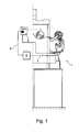
- Fig. 1 is a schematic view of a spinning station 1 of a rotor spinning machine shown.
- the control device 4 serves to control the spinning process at the spinning station 1.
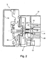
- the spinning device 3 arranged at the spinning station 1 comprises, as in FIG FIG. 2 shown, a spinning rotor 16, the spinning cup 10 at high speed in a rotor housing 9 rotates.
- the spinning rotor 16 is driven by an electric single drive 20.
- the spinning rotor 16 is mounted without contact with its rotor shaft designed as a rotor 11 of the single drive 20 both radially and axially in a magnetic bearing 21.
- the rotor housing 9 is closed during the spinning process by a pivotally mounted cover element 14.
- the lid member 14 and the rotor housing 9 have to open and close a locking device which is actuated by both a service unit and the operator.
- FIG. 2 shows a sectional view of the rotor housing 9, which is part of the spinning device 3.
- the single-motor driven spinning rotor 16 comprises a rotor cup 10, which is arranged on a rotor shaft 11 designed as a rotor 11 of the single-motor drive.
- the rotor 11 is mounted radially and axially contactless in a magnetic bearing assembly 21.
- the magnetic bearing 21 is only hinted at.
- the magnetic bearing 21 also has at the rear end of the rotor shaft a comparable arrangement, not shown here. Further details of a non-contact spinning rotor bearing and the electric single drive are, for example, the DE 198 19 767 A1 or the aforementioned EP 0 972 868 A2 removable.
- a drive housing 15 connects, which is connected to the rotor housing 9.
- the drive housing 15 surrounds the magnetic bearing assembly and the rotor 11, which extends through a connection opening 17 between the drive and the rotor housing in the interior of the rotor housing 9 to receive the rotor cup 10.
- a labyrinth seal 18 seals the connection opening 17.
- the labyrinth seal 18 is arranged in the region of the annular gap between the rotor shaft 11 and the connection opening 17.
- the drive housing 15 is provided with the air inlet 12, which opens into a substantially annular storage volume 13.
- the air inlet 12 is connected via a supply line 7 with a compressed air source 6.
- the compressed air source 6 is in turn connected via a control line 8 to the control device 4 in connection and can be controlled via this.
- the compressed air source 6 is controlled by the same control device 4 as the spinning process at the spinning station 1.
- the compressed air source 6 but also be controlled by its own or by a central control device.
- the control device 4 can operate, for example, a valve, not shown.
- the lid member 14 is closed and the rotor housing 9 is acted upon by means of a vacuum source, not shown, with negative pressure.
- the compressed air source 6 is controlled by the control device 4 so that the drive housing 15 is acted upon by compressed air.
- the compressed air is adjusted so that in the drive housing 15 not only an overpressure against the air pressure prevails in the rotor housing 9, but it is generated in the drive housing 15, an overpressure relative to the ambient pressure.
- the air in the vicinity of textile machinery is usually heavily contaminated with dust and fiber fly. The overpressure prevents dust and / or fiber fly can penetrate into the drive housing 15.
- the labyrinth seal 18 prevents, as long as the spinning rotor rotates, that a pressure equalization takes place between the rotor housing 9 in the drive housing 15. In the drive housing 15 thus no appreciable air movement takes place. Thus, there is a substantially static overpressure in the drive housing. The energy consumption for the compressed air supply is thus low. Only when a spinning break, when the spinning rotor 16 comes to a standstill, the sealing effect of the labyrinth seal 18 after. It comes so through the connection opening 17 to a pressure equalization between the drive housing 15 and the rotor housing 9. The air flow from the drive housing 15 to the rotor housing 9 prevents dust or fiber remains from penetrating the rotor housing 9 in the drive housing 15.
- the supplied compressed air does not necessarily need to be increased at this stage.
- the static pressure in the drive housing 15 decreases in favor of the dynamic pressure.
- the compressed air supply can be increased and the static pressure in the drive housing can be kept constant. Spider breaks are usually short, so energy consumption is not significantly increased.
Landscapes
- Engineering & Computer Science (AREA)
- Mechanical Engineering (AREA)
- Textile Engineering (AREA)
- Spinning Or Twisting Of Yarns (AREA)
Applications Claiming Priority (1)
| Application Number | Priority Date | Filing Date | Title |
|---|---|---|---|
| DE102012015420.8A DE102012015420A1 (de) | 2012-08-02 | 2012-08-02 | Verfahren zum Betreiben einer Spinnvorrichtung, Rotorspinnmaschine aufweisend eine Spinnvorrichtung und Spinnvorrichtung |
Related Parent Applications (1)
| Application Number | Title | Priority Date | Filing Date |
|---|---|---|---|
| DE102012015420 Previously-Filed-Application | 2012-08-02 |
Publications (3)
| Publication Number | Publication Date |
|---|---|
| EP2692916A2 true EP2692916A2 (fr) | 2014-02-05 |
| EP2692916A3 EP2692916A3 (fr) | 2015-05-06 |
| EP2692916B1 EP2692916B1 (fr) | 2016-08-31 |
Family
ID=48746191
Family Applications (1)
| Application Number | Title | Priority Date | Filing Date |
|---|---|---|---|
| EP13003141.2A Not-in-force EP2692916B1 (fr) | 2012-08-02 | 2013-06-20 | Procédé de fonctionnement d'un dispositif de tissage, métier à tisser à rotor présentant un dispositif de tissage et dispositif de tissage |
Country Status (3)
| Country | Link |
|---|---|
| EP (1) | EP2692916B1 (fr) |
| CN (1) | CN103572417B (fr) |
| DE (1) | DE102012015420A1 (fr) |
Cited By (1)
| Publication number | Priority date | Publication date | Assignee | Title |
|---|---|---|---|---|
| EP3237658B1 (fr) * | 2014-12-22 | 2021-08-18 | Rieter Ingolstadt GmbH | Métier à filer à rotor comportant une pluralité d'emplacements de travail et un dispositif d'aspiration |
Families Citing this family (7)
| Publication number | Priority date | Publication date | Assignee | Title |
|---|---|---|---|---|
| DE102014108526A1 (de) * | 2014-06-17 | 2015-12-17 | Maschinenfabrik Rieter Ag | Offenendspinnvorrichtung mit einer Zwischenkammer |
| CZ2015321A3 (cs) * | 2015-05-14 | 2016-12-21 | Rieter Cz S.R.O. | Způsob hromadného zapřádání příze na pracovních místech rotorového dopřádacího stroje a zařízení k jeho provádění |
| DE102015121963A1 (de) * | 2015-12-16 | 2017-06-22 | Rieter Ingolstadt Gmbh | Offenendspinnvorrichtung mit einer Luftzuführung |
| DE102016120989A1 (de) * | 2016-11-03 | 2018-05-03 | Rieter Ingolstadt Gmbh | Offenend-Spinnvorrichtung und Verfahren zum Betreiben einer Offenend-Spinnvorrichtung |
| DE102016123698A1 (de) * | 2016-12-07 | 2018-06-07 | Saurer Germany Gmbh & Co. Kg | Spinnrotor für eine Offenend-Spinnvorrichtung und Offenend- Spinnvorrichtung |
| DE102017123279A1 (de) * | 2017-10-06 | 2019-04-11 | Maschinenfabrik Rieter Ag | Rotorspinnmaschine mit wenigstens einer Luftleitung zum Zuführen von Umgebungsluft in ein Lagergehäuse sowie Spinnvorrichtung einer Rotorspinnmaschine |
| DE102018103876A1 (de) | 2018-02-21 | 2019-08-22 | Maschinenfabrik Rieter Ag | Verfahren zum Betreiben einer Spinnvorrichtung einer Rotorspinnmaschine und Spinnvorrichtung einer Rotorspinnmaschine |
Citations (4)
| Publication number | Priority date | Publication date | Assignee | Title |
|---|---|---|---|---|
| CH571582A5 (fr) | 1973-01-27 | 1976-01-15 | Toyoda Automatic Loom Works | |
| DE19819767A1 (de) | 1998-05-04 | 1999-11-11 | Schlafhorst & Co W | Dämpfungseinrichtung für einen berührungslos gelagerten Rotor |
| EP0972868A2 (fr) | 1998-06-20 | 2000-01-19 | W. SCHLAFHORST AG & CO. | Palier pour une machine de filature à bout ouvert |
| DE102006045589A1 (de) | 2006-09-27 | 2008-04-03 | Oerlikon Textile Gmbh & Co. Kg | Verfahren zum Betreiben einer Spinnvorrichtung |
Family Cites Families (8)
| Publication number | Priority date | Publication date | Assignee | Title |
|---|---|---|---|---|
| CH622291A5 (fr) * | 1976-09-09 | 1981-03-31 | Rieter Ag Maschf | |
| CS205913B1 (en) * | 1979-04-28 | 1981-05-29 | Oldrich Tesar | Open-end spinning machine |
| DE4219683C2 (de) * | 1991-06-28 | 1997-05-07 | Rieter Ingolstadt Spinnerei | Offenend-Spinnmaschine |
| DE4241507A1 (de) * | 1992-12-10 | 1994-06-16 | Schurr Stahlecker & Grill | Lagerung für einen OE-Spinnrotor |
| DE102009013987A1 (de) * | 2009-03-19 | 2010-09-23 | Oerlikon Textile Gmbh & Co. Kg | Offenend-Spinnvorrichtung |
| DE102009030802A1 (de) * | 2009-06-27 | 2009-11-05 | Oerlikon Textile Gmbh & Co. Kg | Offenend-Rotorspinnmaschine |
| DE102009032716A1 (de) * | 2009-07-11 | 2011-01-13 | Oerlikon Textile Gmbh & Co. Kg | Arbeitsstelle einer Offenend-Rotorspinnmaschine und Verfahren zum Betreiben der Arbeitsstelle |
| JP5526915B2 (ja) * | 2010-03-25 | 2014-06-18 | 村田機械株式会社 | 空気紡績装置及び紡績機 |
-
2012
- 2012-08-02 DE DE102012015420.8A patent/DE102012015420A1/de not_active Withdrawn
-
2013
- 2013-06-20 EP EP13003141.2A patent/EP2692916B1/fr not_active Not-in-force
- 2013-08-02 CN CN201310334367.2A patent/CN103572417B/zh not_active Expired - Fee Related
Patent Citations (4)
| Publication number | Priority date | Publication date | Assignee | Title |
|---|---|---|---|---|
| CH571582A5 (fr) | 1973-01-27 | 1976-01-15 | Toyoda Automatic Loom Works | |
| DE19819767A1 (de) | 1998-05-04 | 1999-11-11 | Schlafhorst & Co W | Dämpfungseinrichtung für einen berührungslos gelagerten Rotor |
| EP0972868A2 (fr) | 1998-06-20 | 2000-01-19 | W. SCHLAFHORST AG & CO. | Palier pour une machine de filature à bout ouvert |
| DE102006045589A1 (de) | 2006-09-27 | 2008-04-03 | Oerlikon Textile Gmbh & Co. Kg | Verfahren zum Betreiben einer Spinnvorrichtung |
Cited By (1)
| Publication number | Priority date | Publication date | Assignee | Title |
|---|---|---|---|---|
| EP3237658B1 (fr) * | 2014-12-22 | 2021-08-18 | Rieter Ingolstadt GmbH | Métier à filer à rotor comportant une pluralité d'emplacements de travail et un dispositif d'aspiration |
Also Published As
| Publication number | Publication date |
|---|---|
| EP2692916B1 (fr) | 2016-08-31 |
| EP2692916A3 (fr) | 2015-05-06 |
| CN103572417B (zh) | 2017-07-28 |
| DE102012015420A1 (de) | 2014-02-06 |
| CN103572417A (zh) | 2014-02-12 |
Similar Documents
| Publication | Publication Date | Title |
|---|---|---|
| EP2692916B1 (fr) | Procédé de fonctionnement d'un dispositif de tissage, métier à tisser à rotor présentant un dispositif de tissage et dispositif de tissage | |
| DE102015107621B4 (de) | Elektromotor mit Luftspülfunktion | |
| EP2957662B1 (fr) | Dispositif de filage à bout libre d'une chambre intermédiaire | |
| EP2069562B1 (fr) | Procédé pour l'exploitation d'un dispositif de filature | |
| EP2801646B1 (fr) | Procédé de fonctionnement d'un métier à filer à bout libre, du type filature à rotor | |
| CH688515A5 (de) | Vakuumzentrifuge und Dichtung hierfuer. | |
| DE102012005390A1 (de) | Spinnvorrichtung | |
| DE102004029020A1 (de) | Verfahren und Vorrichtung zum Betreiben einer Offenend-Rotorspinnvorrichtung | |
| DE3837733A1 (de) | Lageranordnung fuer spindeln in textilmaschinen | |
| DE2129796C3 (de) | Offenendspinnvorrichtung mit Rotor | |
| EP1713961B1 (fr) | Arbre de rotor de filature | |
| EP3184679B1 (fr) | Procédé de fonctionnement d'un dispositif de filature à bout libéré et machine de filature à fibre libérée comprenant une pluralité de dispositifs de filature à fibre libérée disposés les uns derrière les autres | |
| EP3530782B1 (fr) | Procédé de fonctionnement d'un dispositif de filage d'un métier à filer à rotor et dispositif de filage d'un métier à filer à rotor | |
| EP3106550B1 (fr) | Rotor de filature pour métier à filer à bout libre à haute vitesse de rotation | |
| DE2333555A1 (de) | Lagerung fuer den spinnrotor einer offenend-spinnvorrichtung | |
| EP3184678A1 (fr) | Dispositif de filage à bout libre doté d'une alimentation en air | |
| EP0926275B1 (fr) | Métier à filer à bout ouvert pour fabriquer des fils à torsion S ou Z | |
| DE19955829A1 (de) | Offenend-Spinnvorrichtung | |
| CH680594A5 (en) | Bearings for roller - has tubular cover over the journals and bearings extending into gap in the roller to exclude dust and fly | |
| DE102010043612A1 (de) | Walzenantrieb, Walze und Verfahren | |
| DE102013006357A1 (de) | Offenend-Spinnvorrichtung und Dichtungselement für eine Offenend-Rotorspinnvorrichtung | |
| DE10237040B4 (de) | Vorrichtung zum Abdichten einer Öffnung eines Rotorgehäuses | |
| DE4241507A1 (de) | Lagerung für einen OE-Spinnrotor | |
| DE19841406A1 (de) | Offenend-Spinnvorrichtung zum Herstellen von Z- oder S-gedrehten Garnen | |
| DE102016120989A1 (de) | Offenend-Spinnvorrichtung und Verfahren zum Betreiben einer Offenend-Spinnvorrichtung |
Legal Events
| Date | Code | Title | Description |
|---|---|---|---|
| AK | Designated contracting states |
Kind code of ref document: A2 Designated state(s): AL AT BE BG CH CY CZ DE DK EE ES FI FR GB GR HR HU IE IS IT LI LT LU LV MC MK MT NL NO PL PT RO RS SE SI SK SM TR |
|
| AX | Request for extension of the european patent |
Extension state: BA ME |
|
| PUAI | Public reference made under article 153(3) epc to a published international application that has entered the european phase |
Free format text: ORIGINAL CODE: 0009012 |
|
| PUAL | Search report despatched |
Free format text: ORIGINAL CODE: 0009013 |
|
| AK | Designated contracting states |
Kind code of ref document: A3 Designated state(s): AL AT BE BG CH CY CZ DE DK EE ES FI FR GB GR HR HU IE IS IT LI LT LU LV MC MK MT NL NO PL PT RO RS SE SI SK SM TR |
|
| AX | Request for extension of the european patent |
Extension state: BA ME |
|
| RIC1 | Information provided on ipc code assigned before grant |
Ipc: D01H 1/20 20060101AFI20150330BHEP |
|
| 17P | Request for examination filed |
Effective date: 20151106 |
|
| RBV | Designated contracting states (corrected) |
Designated state(s): AL AT BE BG CH CY CZ DE DK EE ES FI FR GB GR HR HU IE IS IT LI LT LU LV MC MK MT NL NO PL PT RO RS SE SI SK SM TR |
|
| GRAP | Despatch of communication of intention to grant a patent |
Free format text: ORIGINAL CODE: EPIDOSNIGR1 |
|
| INTG | Intention to grant announced |
Effective date: 20160425 |
|
| GRAS | Grant fee paid |
Free format text: ORIGINAL CODE: EPIDOSNIGR3 |
|
| GRAA | (expected) grant |
Free format text: ORIGINAL CODE: 0009210 |
|
| AK | Designated contracting states |
Kind code of ref document: B1 Designated state(s): AL AT BE BG CH CY CZ DE DK EE ES FI FR GB GR HR HU IE IS IT LI LT LU LV MC MK MT NL NO PL PT RO RS SE SI SK SM TR |
|
| REG | Reference to a national code |
Ref country code: CH Ref legal event code: EP Ref country code: GB Ref legal event code: FG4D Free format text: NOT ENGLISH |
|
| REG | Reference to a national code |
Ref country code: IE Ref legal event code: FG4D Free format text: LANGUAGE OF EP DOCUMENT: GERMAN |
|
| REG | Reference to a national code |
Ref country code: DE Ref legal event code: R096 Ref document number: 502013004235 Country of ref document: DE |
|
| REG | Reference to a national code |
Ref country code: AT Ref legal event code: REF Ref document number: 825061 Country of ref document: AT Kind code of ref document: T Effective date: 20161015 |
|
| REG | Reference to a national code |
Ref country code: LT Ref legal event code: MG4D |
|
| REG | Reference to a national code |
Ref country code: NL Ref legal event code: MP Effective date: 20160831 |
|
| PG25 | Lapsed in a contracting state [announced via postgrant information from national office to epo] |
Ref country code: RS Free format text: LAPSE BECAUSE OF FAILURE TO SUBMIT A TRANSLATION OF THE DESCRIPTION OR TO PAY THE FEE WITHIN THE PRESCRIBED TIME-LIMIT Effective date: 20160831 Ref country code: NO Free format text: LAPSE BECAUSE OF FAILURE TO SUBMIT A TRANSLATION OF THE DESCRIPTION OR TO PAY THE FEE WITHIN THE PRESCRIBED TIME-LIMIT Effective date: 20161130 Ref country code: HR Free format text: LAPSE BECAUSE OF FAILURE TO SUBMIT A TRANSLATION OF THE DESCRIPTION OR TO PAY THE FEE WITHIN THE PRESCRIBED TIME-LIMIT Effective date: 20160831 Ref country code: LT Free format text: LAPSE BECAUSE OF FAILURE TO SUBMIT A TRANSLATION OF THE DESCRIPTION OR TO PAY THE FEE WITHIN THE PRESCRIBED TIME-LIMIT Effective date: 20160831 Ref country code: FI Free format text: LAPSE BECAUSE OF FAILURE TO SUBMIT A TRANSLATION OF THE DESCRIPTION OR TO PAY THE FEE WITHIN THE PRESCRIBED TIME-LIMIT Effective date: 20160831 |
|
| PG25 | Lapsed in a contracting state [announced via postgrant information from national office to epo] |
Ref country code: ES Free format text: LAPSE BECAUSE OF FAILURE TO SUBMIT A TRANSLATION OF THE DESCRIPTION OR TO PAY THE FEE WITHIN THE PRESCRIBED TIME-LIMIT Effective date: 20160831 Ref country code: SE Free format text: LAPSE BECAUSE OF FAILURE TO SUBMIT A TRANSLATION OF THE DESCRIPTION OR TO PAY THE FEE WITHIN THE PRESCRIBED TIME-LIMIT Effective date: 20160831 Ref country code: NL Free format text: LAPSE BECAUSE OF FAILURE TO SUBMIT A TRANSLATION OF THE DESCRIPTION OR TO PAY THE FEE WITHIN THE PRESCRIBED TIME-LIMIT Effective date: 20160831 Ref country code: GR Free format text: LAPSE BECAUSE OF FAILURE TO SUBMIT A TRANSLATION OF THE DESCRIPTION OR TO PAY THE FEE WITHIN THE PRESCRIBED TIME-LIMIT Effective date: 20161201 Ref country code: LV Free format text: LAPSE BECAUSE OF FAILURE TO SUBMIT A TRANSLATION OF THE DESCRIPTION OR TO PAY THE FEE WITHIN THE PRESCRIBED TIME-LIMIT Effective date: 20160831 |
|
| PG25 | Lapsed in a contracting state [announced via postgrant information from national office to epo] |
Ref country code: EE Free format text: LAPSE BECAUSE OF FAILURE TO SUBMIT A TRANSLATION OF THE DESCRIPTION OR TO PAY THE FEE WITHIN THE PRESCRIBED TIME-LIMIT Effective date: 20160831 Ref country code: RO Free format text: LAPSE BECAUSE OF FAILURE TO SUBMIT A TRANSLATION OF THE DESCRIPTION OR TO PAY THE FEE WITHIN THE PRESCRIBED TIME-LIMIT Effective date: 20160831 |
|
| PG25 | Lapsed in a contracting state [announced via postgrant information from national office to epo] |
Ref country code: PT Free format text: LAPSE BECAUSE OF FAILURE TO SUBMIT A TRANSLATION OF THE DESCRIPTION OR TO PAY THE FEE WITHIN THE PRESCRIBED TIME-LIMIT Effective date: 20170102 Ref country code: PL Free format text: LAPSE BECAUSE OF FAILURE TO SUBMIT A TRANSLATION OF THE DESCRIPTION OR TO PAY THE FEE WITHIN THE PRESCRIBED TIME-LIMIT Effective date: 20160831 Ref country code: SK Free format text: LAPSE BECAUSE OF FAILURE TO SUBMIT A TRANSLATION OF THE DESCRIPTION OR TO PAY THE FEE WITHIN THE PRESCRIBED TIME-LIMIT Effective date: 20160831 Ref country code: BG Free format text: LAPSE BECAUSE OF FAILURE TO SUBMIT A TRANSLATION OF THE DESCRIPTION OR TO PAY THE FEE WITHIN THE PRESCRIBED TIME-LIMIT Effective date: 20161130 Ref country code: SM Free format text: LAPSE BECAUSE OF FAILURE TO SUBMIT A TRANSLATION OF THE DESCRIPTION OR TO PAY THE FEE WITHIN THE PRESCRIBED TIME-LIMIT Effective date: 20160831 Ref country code: DK Free format text: LAPSE BECAUSE OF FAILURE TO SUBMIT A TRANSLATION OF THE DESCRIPTION OR TO PAY THE FEE WITHIN THE PRESCRIBED TIME-LIMIT Effective date: 20160831 |
|
| REG | Reference to a national code |
Ref country code: DE Ref legal event code: R097 Ref document number: 502013004235 Country of ref document: DE |
|
| PLBE | No opposition filed within time limit |
Free format text: ORIGINAL CODE: 0009261 |
|
| STAA | Information on the status of an ep patent application or granted ep patent |
Free format text: STATUS: NO OPPOSITION FILED WITHIN TIME LIMIT |
|
| 26N | No opposition filed |
Effective date: 20170601 |
|
| PG25 | Lapsed in a contracting state [announced via postgrant information from national office to epo] |
Ref country code: SI Free format text: LAPSE BECAUSE OF FAILURE TO SUBMIT A TRANSLATION OF THE DESCRIPTION OR TO PAY THE FEE WITHIN THE PRESCRIBED TIME-LIMIT Effective date: 20160831 |
|
| PG25 | Lapsed in a contracting state [announced via postgrant information from national office to epo] |
Ref country code: MC Free format text: LAPSE BECAUSE OF FAILURE TO SUBMIT A TRANSLATION OF THE DESCRIPTION OR TO PAY THE FEE WITHIN THE PRESCRIBED TIME-LIMIT Effective date: 20160831 |
|
| REG | Reference to a national code |
Ref country code: CH Ref legal event code: PL |
|
| GBPC | Gb: european patent ceased through non-payment of renewal fee |
Effective date: 20170620 |
|
| REG | Reference to a national code |
Ref country code: IE Ref legal event code: MM4A |
|
| REG | Reference to a national code |
Ref country code: FR Ref legal event code: ST Effective date: 20180228 |
|
| PG25 | Lapsed in a contracting state [announced via postgrant information from national office to epo] |
Ref country code: CH Free format text: LAPSE BECAUSE OF NON-PAYMENT OF DUE FEES Effective date: 20170630 Ref country code: LI Free format text: LAPSE BECAUSE OF NON-PAYMENT OF DUE FEES Effective date: 20170630 Ref country code: LU Free format text: LAPSE BECAUSE OF NON-PAYMENT OF DUE FEES Effective date: 20170620 Ref country code: IE Free format text: LAPSE BECAUSE OF NON-PAYMENT OF DUE FEES Effective date: 20170620 Ref country code: GB Free format text: LAPSE BECAUSE OF NON-PAYMENT OF DUE FEES Effective date: 20170620 |
|
| PG25 | Lapsed in a contracting state [announced via postgrant information from national office to epo] |
Ref country code: FR Free format text: LAPSE BECAUSE OF NON-PAYMENT OF DUE FEES Effective date: 20170630 |
|
| REG | Reference to a national code |
Ref country code: BE Ref legal event code: MM Effective date: 20170630 |
|
| PGFP | Annual fee paid to national office [announced via postgrant information from national office to epo] |
Ref country code: CZ Payment date: 20180524 Year of fee payment: 6 |
|
| PG25 | Lapsed in a contracting state [announced via postgrant information from national office to epo] |
Ref country code: BE Free format text: LAPSE BECAUSE OF NON-PAYMENT OF DUE FEES Effective date: 20170630 |
|
| REG | Reference to a national code |
Ref country code: DE Ref legal event code: R081 Ref document number: 502013004235 Country of ref document: DE Owner name: SAURER SPINNING SOLUTIONS GMBH & CO. KG, DE Free format text: FORMER OWNER: SAURER GERMANY GMBH & CO. KG, 42897 REMSCHEID, DE |
|
| PG25 | Lapsed in a contracting state [announced via postgrant information from national office to epo] |
Ref country code: MT Free format text: LAPSE BECAUSE OF FAILURE TO SUBMIT A TRANSLATION OF THE DESCRIPTION OR TO PAY THE FEE WITHIN THE PRESCRIBED TIME-LIMIT Effective date: 20160831 |
|
| PG25 | Lapsed in a contracting state [announced via postgrant information from national office to epo] |
Ref country code: AL Free format text: LAPSE BECAUSE OF FAILURE TO SUBMIT A TRANSLATION OF THE DESCRIPTION OR TO PAY THE FEE WITHIN THE PRESCRIBED TIME-LIMIT Effective date: 20160831 |
|
| PGFP | Annual fee paid to national office [announced via postgrant information from national office to epo] |
Ref country code: DE Payment date: 20180625 Year of fee payment: 6 Ref country code: IT Payment date: 20180629 Year of fee payment: 6 |
|
| PG25 | Lapsed in a contracting state [announced via postgrant information from national office to epo] |
Ref country code: HU Free format text: LAPSE BECAUSE OF FAILURE TO SUBMIT A TRANSLATION OF THE DESCRIPTION OR TO PAY THE FEE WITHIN THE PRESCRIBED TIME-LIMIT; INVALID AB INITIO Effective date: 20130620 |
|
| REG | Reference to a national code |
Ref country code: AT Ref legal event code: MM01 Ref document number: 825061 Country of ref document: AT Kind code of ref document: T Effective date: 20180620 |
|
| PG25 | Lapsed in a contracting state [announced via postgrant information from national office to epo] |
Ref country code: CY Free format text: LAPSE BECAUSE OF NON-PAYMENT OF DUE FEES Effective date: 20160831 |
|
| PG25 | Lapsed in a contracting state [announced via postgrant information from national office to epo] |
Ref country code: MK Free format text: LAPSE BECAUSE OF FAILURE TO SUBMIT A TRANSLATION OF THE DESCRIPTION OR TO PAY THE FEE WITHIN THE PRESCRIBED TIME-LIMIT Effective date: 20160831 |
|
| PG25 | Lapsed in a contracting state [announced via postgrant information from national office to epo] |
Ref country code: AT Free format text: LAPSE BECAUSE OF NON-PAYMENT OF DUE FEES Effective date: 20180620 |
|
| REG | Reference to a national code |
Ref country code: DE Ref legal event code: R119 Ref document number: 502013004235 Country of ref document: DE |
|
| PG25 | Lapsed in a contracting state [announced via postgrant information from national office to epo] |
Ref country code: CZ Free format text: LAPSE BECAUSE OF NON-PAYMENT OF DUE FEES Effective date: 20190620 |
|
| PG25 | Lapsed in a contracting state [announced via postgrant information from national office to epo] |
Ref country code: TR Free format text: LAPSE BECAUSE OF FAILURE TO SUBMIT A TRANSLATION OF THE DESCRIPTION OR TO PAY THE FEE WITHIN THE PRESCRIBED TIME-LIMIT Effective date: 20160831 |
|
| PG25 | Lapsed in a contracting state [announced via postgrant information from national office to epo] |
Ref country code: DE Free format text: LAPSE BECAUSE OF NON-PAYMENT OF DUE FEES Effective date: 20200101 Ref country code: IT Free format text: LAPSE BECAUSE OF NON-PAYMENT OF DUE FEES Effective date: 20190620 |
|
| PG25 | Lapsed in a contracting state [announced via postgrant information from national office to epo] |
Ref country code: IS Free format text: LAPSE BECAUSE OF FAILURE TO SUBMIT A TRANSLATION OF THE DESCRIPTION OR TO PAY THE FEE WITHIN THE PRESCRIBED TIME-LIMIT Effective date: 20161231 |