EP2693145B1 - Roof for ladle furnace - Google Patents
Roof for ladle furnace Download PDFInfo
- Publication number
- EP2693145B1 EP2693145B1 EP11862678.7A EP11862678A EP2693145B1 EP 2693145 B1 EP2693145 B1 EP 2693145B1 EP 11862678 A EP11862678 A EP 11862678A EP 2693145 B1 EP2693145 B1 EP 2693145B1
- Authority
- EP
- European Patent Office
- Prior art keywords
- cotter
- bodies
- roof
- ladle furnace
- dust collection
- Prior art date
- Legal status (The legal status is an assumption and is not a legal conclusion. Google has not performed a legal analysis and makes no representation as to the accuracy of the status listed.)
- Not-in-force
Links
Images



Classifications
-
- C—CHEMISTRY; METALLURGY
- C21—METALLURGY OF IRON
- C21C—PROCESSING OF PIG-IRON, e.g. REFINING, MANUFACTURE OF WROUGHT-IRON OR STEEL; TREATMENT IN MOLTEN STATE OF FERROUS ALLOYS
- C21C7/00—Treating molten ferrous alloys, e.g. steel, not covered by groups C21C1/00 - C21C5/00
- C21C7/10—Handling in a vacuum
-
- F—MECHANICAL ENGINEERING; LIGHTING; HEATING; WEAPONS; BLASTING
- F27—FURNACES; KILNS; OVENS; RETORTS
- F27D—DETAILS OR ACCESSORIES OF FURNACES, KILNS, OVENS OR RETORTS, IN SO FAR AS THEY ARE OF KINDS OCCURRING IN MORE THAN ONE KIND OF FURNACE
- F27D1/00—Casings; Linings; Walls; Roofs
- F27D1/02—Crowns; Roofs
-
- F—MECHANICAL ENGINEERING; LIGHTING; HEATING; WEAPONS; BLASTING
- F27—FURNACES; KILNS; OVENS; RETORTS
- F27D—DETAILS OR ACCESSORIES OF FURNACES, KILNS, OVENS OR RETORTS, IN SO FAR AS THEY ARE OF KINDS OCCURRING IN MORE THAN ONE KIND OF FURNACE
- F27D17/00—Arrangements for using waste heat; Arrangements for using, or disposing of, waste gases
- F27D17/30—Arrangements for extraction or collection of waste gases; Hoods therefor
- F27D17/304—Arrangements for extraction or collection of waste gases; Hoods therefor specially adapted for electric arc furnaces
-
- F—MECHANICAL ENGINEERING; LIGHTING; HEATING; WEAPONS; BLASTING
- F27—FURNACES; KILNS; OVENS; RETORTS
- F27B—FURNACES, KILNS, OVENS OR RETORTS IN GENERAL; OPEN SINTERING OR LIKE APPARATUS
- F27B14/00—Crucible or pot furnaces
- F27B14/08—Details specially adapted for crucible or pot furnaces
- F27B14/10—Crucibles
- F27B14/12—Covers therefor
-
- F—MECHANICAL ENGINEERING; LIGHTING; HEATING; WEAPONS; BLASTING
- F27—FURNACES; KILNS; OVENS; RETORTS
- F27D—DETAILS OR ACCESSORIES OF FURNACES, KILNS, OVENS OR RETORTS, IN SO FAR AS THEY ARE OF KINDS OCCURRING IN MORE THAN ONE KIND OF FURNACE
- F27D1/00—Casings; Linings; Walls; Roofs
- F27D1/12—Casings; Linings; Walls; Roofs incorporating cooling arrangements
-
- F—MECHANICAL ENGINEERING; LIGHTING; HEATING; WEAPONS; BLASTING
- F27—FURNACES; KILNS; OVENS; RETORTS
- F27D—DETAILS OR ACCESSORIES OF FURNACES, KILNS, OVENS OR RETORTS, IN SO FAR AS THEY ARE OF KINDS OCCURRING IN MORE THAN ONE KIND OF FURNACE
- F27D1/00—Casings; Linings; Walls; Roofs
- F27D1/18—Door frames; Doors, lids or removable covers
- F27D1/1808—Removable covers
-
- F—MECHANICAL ENGINEERING; LIGHTING; HEATING; WEAPONS; BLASTING
- F27—FURNACES; KILNS; OVENS; RETORTS
- F27D—DETAILS OR ACCESSORIES OF FURNACES, KILNS, OVENS OR RETORTS, IN SO FAR AS THEY ARE OF KINDS OCCURRING IN MORE THAN ONE KIND OF FURNACE
- F27D1/00—Casings; Linings; Walls; Roofs
- F27D1/18—Door frames; Doors, lids or removable covers
- F27D1/1808—Removable covers
- F27D1/1816—Removable covers specially adapted for arc furnaces
Definitions
- the present invention relates, in general, to roofs for ladle furnaces and, more particularly, to a roof for a ladle furnace which can be compatible with a dust collection elbow or a dust collection hood depending on operating conditions.
- a steel manufacturing process in which steel is manufactured using iron ore as raw material begins with an ironmaking operation of melting iron ore in a shaft furnace.
- Molten iron which is formed by melting iron ore undergoes a primary refining process of successively conducting operations such as dephosphorization, decarburization, deoxidation, etc. and removing impurities from the molten iron, thus forming molten steel.
- Molten steel from which impurities have been removed is treated through a secondary refining process, whereby fine component adjustment is realized. Subsequently, the molten steel is transferred to a continuous casting process.
- a half-finished product is formed through the continuous casting process.
- the half-finished product is shaped by a final forming operation such as rolling, thus forming a final product.
- An LF ladle furnace
- An electric furnace is a device which is used to finely adjust components of molten steel and desulfurize it after the melting of scrap and the primary refining process are conducted by an electric furnace.
- a secondary refining process of adjusting components of molten steel is conducted to make it appropriate for desulfurization and deoxidation in such a way that supplementary material is added to molten steel and then it is treated by Ar bubbling and is arc-heated.
- Documents DE 102 19 488 A and DE 10 2008 012 280 A show examples of furnace roofs with openings for electrodes and an exhaust port for the removal of fumes. Furthermore, documents US 2006/091590 A and US 6 084 902 A show furnace roofs that are water-cooled.
- an object of the present invention is to provide a roof for a ladle furnace which covers an upper end of the ladle furnace and is able to be compatible with a dust collection elbow or a dust collection hood depending on operating conditions.
- Another aspect of the present invention is to provide a roof for a ladle furnace in which the opening or closing operation of a carbon supply port and a sampling port can be precisely controlled.
- the present invention provides a roof for a ladle furnace according to claim 1. Further advantageous embodiments are set out in the dependent claims.
- the dust collection hood may have: a third seating hole formed in an upper portion of the dust collection hood so that the small ceiling is seated into the third seating hole; and a plurality of third cotter bodies to which the small ceiling that is seated into the third seating hole is fastened, wherein the third cotter bodies vertically protrude from the dust collection hood at positions adjacent to the third seating hole.
- a single roof for a ladle furnace can be compatible with a dust collection elbow or a dust collection hood depending on operating conditions. Therefore, the present invention can solve the conventional problem in which the entirety of the roof must be replaced with another when operating conditions are changed. In addition, because it is not required to manufacture different kinds of roofs that correspond to all operating conditions, the production cost related to manufacture of the roof can be reduced.
- port covers which are provided on an opening of a carbon supply port and an opening of a sampling supply port are configured such that they are respectively rotated by opening control cylinders in the directions facing the openings of the carbon supply port and the sampling supply port. Therefore, even if each port cover is deformed by heat transferred from the ladle furnace, the opening or closing operation can be precisely conducted.
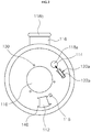
- Fig. 1 is a perspective view illustrating a roof for a ladle furnace, according to the present invention.
- the ladle furnace roof 100 according to the present invention has a side part 102 which has a vertical cylindrical shape, and a cover part 104 which covers an open upper end of the side part 102.
- the ladle furnace roof 100 is installed to cover the upper end of the ladle furnace (not shown).
- the ladle furnace roof 100 covers the upper end of he ladle furnace and functions to remove impure elements (sulfur, gas, etc.) generated in the ladle furnace during refining operation and protect the surroundings from melt or slag that spatters during the operation.
- a small ceiling into which electrodes are inserted is seated in the ladle furnace roof 100.
- a carbon supply port, an auxiliary raw material supply hole, a sampling supply port, etc. are installed around the small ceiling.
- ladle furnace roofs are classified into a roof provided with a dust collection elbow or a roof provided with a dust collection hood for sucking impure elements generated in the ladle furnace and discharging them from the ladle furnace.
- the present invention provides a ladle furnace roof which can be compatible with a dust collection elbow or with a dust collection hood depending on operating conditions, in other words, whether to prevent the electrodes installed in the small ceiling from being damaged or worn or to obtain superior dust collection effect.
- a cooling pipe 106 is provided in the side part 102 and the cover part 104 so as to cool heat generated from the ladle furnace.
- the outer surfaces of the side part 102 and the cover part 104 are covered with a shell 108.
- a cooling water supply pipe (not shown) and a cooling water discharge pipe (not shown) are connected to the cooling pipe 106.
- the sampling supply port 116 is provided at a predetermined position in the side part 102.
- a first seating hole 110, a second seating hole 112, a carbon supply port 114, and an auxiliary raw material supply hole 115 are formed in the cover part 104.
- the first seating hole 110 is formed in a central portion of the cover part 104.
- the second seating hole 112, the carbon supply port 114 and the auxiliary raw material supply hole 115 are provided in the cover part 104 at positions adjacent to the first seating hole 110.
- a small ceiling 160 provided with electrodes E and a dust collection elbow 180, or a dust collection hood 170 provided with a small ceiling 160 and a water cooling panel 190 are selectively provided in the cover part 104.
- the small ceiling 160 and the dust collection elbow 180 are respectively seated into the first seating hole 110 and the second seating hole 112 and fastened to the cover part 104.
- the dust collection hood 170 and the water cooling panel 190 are respectively seated into the first seating hole 110 and the second seating hole 112 and fastened to the cover part 104.
- a plurality of first cotter bodies 130 vertically protrude from the cover part 104 around the first seating hole 110 so that the small ceiling 160 or the dust collection hood 170 can be fastened to the cover part 104 by the first cotter bodies 130.
- a plurality of second cotter bodies 140 vertically protrude from the cover part 104 around the second seating hole 112 so that the dust collection elbow 180 or the water cooling panel 190 is fastened to the cover part 104 by the second cotter bodies 140.
- a small ceiling connection flange 162 that has insert holes 164 and a hood connection flange 172 that has insert holes 174 are respectively provided on the small ceiling 160 and the dust collection hood 170, wherein the first cotter bodies 130 are inserted into the respective insert holes 164 or 174.
- an elbow connection flange 182 that has insert holes 184 and a water cooling panel connection flange 192 that has insert holes 194 are respectively provided on the dust collection elbow 180 and the water cooling panel 190, wherein the second cotter bodies 140 are inserted into the respective insert holes 184 or 194.
- the small ceiling connection flange 162 or the hood connection flange 172 that is fitted over the first cotter bodies 130 is fastened to the first cotter bodies 130 by cotter pins 134 that are inserted into corresponding cotter holes 132 formed in the respective first cotter body 130.
- the elbow connection flange 182 or the water cooling panel connection flange 192 that is fitted over the second cotter bodies 140 is fastened to the second cotter bodies 140 by cotter pins 144 that are inserted into corresponding cotter ho les 142 formed in the respective second cotter body 140.
- a third seating hole 176 is formed in an upper portion of the dust collection hood 170 that is fastened to the first cotter bodies 130, and the small ceiling 160 provided with the electrodes E is seated into the third seating hole 176.
- a plurality of third cotter bodies 150 for fixing the small ceiling 160 to the dust collection hood 170 vertically protrude from the dust collection hood 170 at positions adjacent to the third seating hole 176.
- the insert holes 164 formed in the small ceiling connection flange are fitted over the respective third cotter bodies 150, and the small ceiling connection flange 162 that is fitted over the third cotter bodies 150 is fastened to the third cotter bodies 150 by cotter pins 154 that are inserted into corresponding cotter holes 152 formed in the respective third cotter body 150.
- At least one support block 179 is provided between the cover part 104 and the exhaust duct 178 that is provided on an outer circumferential surface of the dust collection hood 170 so that the exhaust duct 178 can be supported by the support block 179.
- a panel cooling pipe 196 is arranged on the water cooling panel 190, which covers the second seating hole 112, so as to cool heat transferred from the ladle furnace.
- a cooling water supply pipe (not shown) and a cooling water discharge pipe (not shown) are connected to the panel cooling pipe 196.
- port covers 118a and 118b and port control units 120a and 120b are respectively provided on the sampling supply port 116 formed in the side part 102 and the carbon supply port 114 formed in the cover part 104.
- the port covers 118a and 118b respectively open or close an opening of the carbon supply port 114 and an opening of the sampling supply port 116.
- the port covers 118a and 118b are respectively coupled to the carbon supply port 114 and the sampling supply port 116 so as to be rotatable in directions facing the openings of the carbon supply port 114 and the sampling supply port 116.
- the port covers 118a and 118b are respectively opened or closed by the port control units 120a and 120b.
- the port control units 120a and 120b respectively include opening control cylinders 122a and 122b which are disposed adjacent to the carbon supply port 114 and the sampling port 116.
- the port control units 120a and 120b further respectively include fixed brackets 124a and 124b which respectively extend from the outer surfaces of the carbon supply port 114 and the sampling supply port 116 towards the corresponding port covers 118a and 118b, and rotating brackets 126a and 126b which respectively extend from the port covers 118a and 118b and are rotatably coupled to the corresponding fixed brackets 124a and 124b by hinges.
- Extension ends of the rotating brackets 126a and 126b are respectively connected to cylinder rods 128a and 128b which are extended from or contracted into the opening control cylinders 122a and 122b. That is, when the cylinder rods 128a and 128b which are respectively connected to the rotating brackets 126a and 126b are contracted by the operation of the opening control cylinders 122a and 122b, the port covers 118a and 118b respectively open the carbon supply port 114 and the sampling supply port 116. When the cylinder rods 128a and 128b are extended by the operation of the opening control cylinders 122a and 122b, the port covers 118a and 118b respectively close the carbon supply port 114 and the sampling supply port 116.
- a cooling passage (not shown) is formed in the port cover 118a of the carbon supply port 114 to cool heat transferred from the ladle furnace.
- the port cover 118b of the sampling supply port 116 which receives heat from the ladle furnace is cooled by an air-cooling method.
- an air-cooling passage 129a through which air flows and a plurality of air holes 129b connected to the air-cooling passage 129a are formed in the port cover 118b of the sampling supply port 116.
- the ladle furnace roof 100 according to the present invention can be compatible with the dust collection elbow 180 or the dust collection hood 170 depending on operating conditions. Therefore, the present invention can solve the conventional problem in which the entirety of the roof 100 must be replaced with when operating conditions are changed. In addition, because it is not required to manufacture different kinds of roofs that correspond to differing operating conditions, the production cost related to manufacture of the roof 100 can be reduced.
- the port covers 118a and 118b which are provided on the opening of the carbon support port 114 and the opening of the sampling supply port 116 are configured such that they are respectively rotated by the opening control cylinders 122a and 122b in the directions facing the openings of the carbon supply port 114 and the sampling supply port 116. Therefore, even if the port cover 118a or 118b is deformed by heat transferred from the ladle furnace, the opening or closing operation can be precisely conducted.
Landscapes
- Engineering & Computer Science (AREA)
- Mechanical Engineering (AREA)
- General Engineering & Computer Science (AREA)
- Chemical & Material Sciences (AREA)
- Materials Engineering (AREA)
- Metallurgy (AREA)
- Organic Chemistry (AREA)
- Environmental & Geological Engineering (AREA)
- Waste-Gas Treatment And Other Accessory Devices For Furnaces (AREA)
- Furnace Housings, Linings, Walls, And Ceilings (AREA)
- Casting Support Devices, Ladles, And Melt Control Thereby (AREA)
- Vertical, Hearth, Or Arc Furnaces (AREA)
Applications Claiming Priority (4)
| Application Number | Priority Date | Filing Date | Title |
|---|---|---|---|
| KR20110028502 | 2011-03-30 | ||
| KR20110040072 | 2011-04-28 | ||
| KR1020110123651A KR101299096B1 (ko) | 2011-03-30 | 2011-11-24 | 래들로용 지붕 |
| PCT/KR2011/010140 WO2012134037A1 (ko) | 2011-03-30 | 2011-12-27 | 래들로용 지붕 |
Publications (3)
| Publication Number | Publication Date |
|---|---|
| EP2693145A1 EP2693145A1 (en) | 2014-02-05 |
| EP2693145A4 EP2693145A4 (en) | 2014-10-01 |
| EP2693145B1 true EP2693145B1 (en) | 2017-05-17 |
Family
ID=47282470
Family Applications (1)
| Application Number | Title | Priority Date | Filing Date |
|---|---|---|---|
| EP11862678.7A Not-in-force EP2693145B1 (en) | 2011-03-30 | 2011-12-27 | Roof for ladle furnace |
Country Status (6)
| Country | Link |
|---|---|
| US (1) | US20140029642A1 (ko) |
| EP (1) | EP2693145B1 (ko) |
| JP (1) | JP5719475B2 (ko) |
| KR (1) | KR101299096B1 (ko) |
| CN (1) | CN103459962B (ko) |
| WO (1) | WO2012134037A1 (ko) |
Families Citing this family (3)
| Publication number | Priority date | Publication date | Assignee | Title |
|---|---|---|---|---|
| EP3824235A4 (en) * | 2018-07-17 | 2022-04-20 | Systems Spray-Cooled, Inc. | METALLURGICAL FURNACE WITH INTEGRATED GAS VENTING PIPE |
| CN109405569A (zh) * | 2018-12-04 | 2019-03-01 | 天津博昶节能科技发展有限公司 | 一种用于烤包器的烟气回收装置 |
| CN117006850B (zh) * | 2023-07-10 | 2025-09-23 | 江西金德铅业股份有限公司 | 一种适配性高的反射炉炉顶加固装置 |
Citations (1)
| Publication number | Priority date | Publication date | Assignee | Title |
|---|---|---|---|---|
| JPS6169256U (ko) * | 1984-10-11 | 1986-05-12 |
Family Cites Families (28)
| Publication number | Priority date | Publication date | Assignee | Title |
|---|---|---|---|---|
| US4021603A (en) * | 1975-10-22 | 1977-05-03 | Ishikawajima-Harima Jukogyo Kabushiki Kaisha | Roof for arc furnace |
| US4146742A (en) * | 1978-01-05 | 1979-03-27 | Longenecker Levi S | Electric furnace having a side wall to roof smoke hole mounting |
| FR2476823B1 (fr) * | 1980-02-22 | 1985-06-28 | Clesid Sa | Voute perfectionnee pour four electrique a arc |
| DE3147337C2 (de) * | 1981-11-28 | 1985-03-14 | SIDEPAL S.A. Société Industrielle de Participations Luxembourgeoise, Luxemburg/Luxembourg | Wassergekühlte Haube für metallurgische Gefäße, insbesondere Gießpfannen |
| JPS6013014A (ja) * | 1983-06-30 | 1985-01-23 | Ishikawajima Harima Heavy Ind Co Ltd | 取鍋精錬装置 |
| US4545058A (en) * | 1983-12-15 | 1985-10-01 | Amsted Industries Incorporated | Electric furnace refractory roof form |
| JPS6345672Y2 (ko) * | 1985-02-05 | 1988-11-28 | ||
| JPS61186413A (ja) * | 1985-02-12 | 1986-08-20 | Daido Steel Co Ltd | 取鍋精錬装置 |
| JPH0235798Y2 (ko) * | 1985-07-26 | 1990-09-28 | ||
| CN1018950B (zh) * | 1990-09-18 | 1992-11-04 | 朱继伦 | 转动中心高温扑尘罩 |
| CN2160872Y (zh) * | 1993-07-22 | 1994-04-06 | 工贸联营烟台石化管件厂 | 炼钢电炉排管水冷炉盖 |
| JPH07145420A (ja) * | 1993-09-30 | 1995-06-06 | Ishikawajima Harima Heavy Ind Co Ltd | 電気アーク溶解炉 |
| IT1299736B1 (it) * | 1998-02-11 | 2000-04-04 | Danieli Off Mecc | Volta raffreddata per forni elettrici ad arco e per forni siviera |
| US5999558A (en) * | 1998-08-13 | 1999-12-07 | Ucar Carbon Technology Corporation | Integral spray cooled furnace roof and fume elbow |
| JP2000319716A (ja) * | 1999-05-07 | 2000-11-21 | Nippon Steel Corp | 溶銑の連続精錬法 |
| US6084902A (en) * | 1999-07-09 | 2000-07-04 | Fuchs Systems, Inc. | Electric arc furnace having monolithic water-cooled roof |
| KR200181923Y1 (ko) * | 1999-12-22 | 2000-05-15 | 포항종합제철주식회사 | 전로 트라니온 링 코터핀과 심라이너의 이격 방지장치 |
| JP2001194070A (ja) * | 2000-01-07 | 2001-07-17 | Godo Steel Ltd | 電気炉用炉蓋 |
| JP2001221423A (ja) * | 2000-02-04 | 2001-08-17 | Nkk Corp | 溶融メタルの流出量調整装置 |
| CN2514003Y (zh) * | 2001-12-21 | 2002-10-02 | 烟台冶金水冷件厂 | 炼钢电炉排管水冷炉盖 |
| DE10219488A1 (de) * | 2002-04-30 | 2003-11-13 | Messer Griesheim Gmbh | Vorrichtung und Verfahren zur Eindüsung von Sauerstoff und/oder Brennstoff |
| US7452499B2 (en) * | 2004-10-29 | 2008-11-18 | Systems Spray-Cooled, Inc. | Furnace cooling system and method |
| FI118825B (fi) * | 2005-04-29 | 2008-03-31 | Outotec Oyj | Valokaariuunin kansi |
| KR101186198B1 (ko) * | 2007-08-13 | 2012-10-08 | 주식회사 포스코 | 전극봉 홀더 보호장치 및 이를 이용한 전기로 |
| DE102008012280A1 (de) * | 2008-03-03 | 2009-09-10 | Fuchs Technology Ag | Lichtbogenofen |
| KR101026515B1 (ko) * | 2010-03-19 | 2011-04-01 | 주식회사 엠텍이엔지 | 레이들 로의 루프장치 |
| CN201697474U (zh) * | 2010-06-10 | 2011-01-05 | 罗永忠 | 一种熔炉的上盖装置 |
| US8858867B2 (en) * | 2011-02-01 | 2014-10-14 | Superior Machine Co. of South Carolina, Inc. | Ladle metallurgy furnace having improved roof |
-
2011
- 2011-11-24 KR KR1020110123651A patent/KR101299096B1/ko not_active Expired - Fee Related
- 2011-12-27 WO PCT/KR2011/010140 patent/WO2012134037A1/ko not_active Ceased
- 2011-12-27 JP JP2014502439A patent/JP5719475B2/ja not_active Expired - Fee Related
- 2011-12-27 CN CN201180069836.1A patent/CN103459962B/zh not_active Expired - Fee Related
- 2011-12-27 EP EP11862678.7A patent/EP2693145B1/en not_active Not-in-force
-
2013
- 2013-09-27 US US14/040,410 patent/US20140029642A1/en not_active Abandoned
Patent Citations (1)
| Publication number | Priority date | Publication date | Assignee | Title |
|---|---|---|---|---|
| JPS6169256U (ko) * | 1984-10-11 | 1986-05-12 |
Also Published As
| Publication number | Publication date |
|---|---|
| EP2693145A4 (en) | 2014-10-01 |
| CN103459962B (zh) | 2016-06-01 |
| JP5719475B2 (ja) | 2015-05-20 |
| WO2012134037A1 (ko) | 2012-10-04 |
| KR101299096B1 (ko) | 2013-08-28 |
| US20140029642A1 (en) | 2014-01-30 |
| EP2693145A1 (en) | 2014-02-05 |
| CN103459962A (zh) | 2013-12-18 |
| JP2014509727A (ja) | 2014-04-21 |
| KR20120111893A (ko) | 2012-10-11 |
Similar Documents
| Publication | Publication Date | Title |
|---|---|---|
| EP2693145B1 (en) | Roof for ladle furnace | |
| EP3676550B1 (en) | Split roof for a metallurgical furnace | |
| US6602461B2 (en) | Arrangement for pouring a pourable melt made up of a copper alloy | |
| EP3612649B1 (en) | Cooling system for a surface of a metallurgical furnace | |
| KR100920977B1 (ko) | 용탕 이송 용기 및 이를 이용한 용탕 이송 방법 | |
| JP4499772B2 (ja) | 自溶炉の点検孔構造体 | |
| RU2495941C2 (ru) | Электродуговая печь | |
| WO2018140909A1 (en) | Top loading roof for electric arc, metallurgical or refining furnaces and system thereof | |
| CN116868019A (zh) | 带影像装置的电炉 | |
| KR101167131B1 (ko) | 냉각반을 갖는 고로 | |
| JP2000256727A (ja) | 冶金炉の水冷フランジ | |
| CN213624232U (zh) | 一种可滑动水冷式喂丝孔盖板 | |
| KR101485035B1 (ko) | 가스 주입기 및 이를 구비하는 용탕 처리 장치 | |
| KR20260049904A (ko) | 전기로 소천정 | |
| KR101676117B1 (ko) | 전로 유지보수 방법 | |
| JP2006214647A (ja) | 取鍋精錬用の水冷蓋および精錬処理方法 | |
| JP3297045B2 (ja) | 銅の製錬装置 | |
| US20230280096A1 (en) | Spray-cooled furnace roof with gravity drain | |
| KR20000064802A (ko) | 감압 정련로 | |
| JP3724134B2 (ja) | 炉体分割式転炉 | |
| JP4304944B2 (ja) | 溶融金属収納容器およびその外壁冷却方法 | |
| US8262985B2 (en) | Smelting or reduction furnace, in particular electric arc furnace with an open, semi-closed or closed configuration | |
| KR20100060071A (ko) | 공랭식 냉각장치 | |
| CN120555680A (zh) | 一种废坯无损回收的钢坯冶炼方法 | |
| JP2000146452A (ja) | 固定式製錬炉 |
Legal Events
| Date | Code | Title | Description |
|---|---|---|---|
| PUAI | Public reference made under article 153(3) epc to a published international application that has entered the european phase |
Free format text: ORIGINAL CODE: 0009012 |
|
| 17P | Request for examination filed |
Effective date: 20130930 |
|
| AK | Designated contracting states |
Kind code of ref document: A1 Designated state(s): AL AT BE BG CH CY CZ DE DK EE ES FI FR GB GR HR HU IE IS IT LI LT LU LV MC MK MT NL NO PL PT RO RS SE SI SK SM TR |
|
| DAX | Request for extension of the european patent (deleted) | ||
| A4 | Supplementary search report drawn up and despatched |
Effective date: 20140828 |
|
| RIC1 | Information provided on ipc code assigned before grant |
Ipc: F27D 1/18 20060101ALI20140822BHEP Ipc: F27D 17/00 20060101ALI20140822BHEP Ipc: F27D 1/02 20060101AFI20140822BHEP Ipc: C21C 7/10 20060101ALI20140822BHEP |
|
| 17Q | First examination report despatched |
Effective date: 20150717 |
|
| REG | Reference to a national code |
Ref country code: DE Ref legal event code: R079 Ref document number: 602011038142 Country of ref document: DE Free format text: PREVIOUS MAIN CLASS: F27D0001020000 Ipc: F27B0014120000 |
|
| RIC1 | Information provided on ipc code assigned before grant |
Ipc: F27B 14/12 20060101AFI20161019BHEP Ipc: C21C 7/10 20060101ALI20161019BHEP Ipc: F27D 1/18 20060101ALI20161019BHEP |
|
| GRAP | Despatch of communication of intention to grant a patent |
Free format text: ORIGINAL CODE: EPIDOSNIGR1 |
|
| INTG | Intention to grant announced |
Effective date: 20161208 |
|
| GRAS | Grant fee paid |
Free format text: ORIGINAL CODE: EPIDOSNIGR3 |
|
| GRAA | (expected) grant |
Free format text: ORIGINAL CODE: 0009210 |
|
| AK | Designated contracting states |
Kind code of ref document: B1 Designated state(s): AL AT BE BG CH CY CZ DE DK EE ES FI FR GB GR HR HU IE IS IT LI LT LU LV MC MK MT NL NO PL PT RO RS SE SI SK SM TR |
|
| REG | Reference to a national code |
Ref country code: GB Ref legal event code: FG4D |
|
| REG | Reference to a national code |
Ref country code: CH Ref legal event code: EP |
|
| REG | Reference to a national code |
Ref country code: IE Ref legal event code: FG4D |
|
| REG | Reference to a national code |
Ref country code: AT Ref legal event code: REF Ref document number: 894846 Country of ref document: AT Kind code of ref document: T Effective date: 20170615 |
|
| REG | Reference to a national code |
Ref country code: DE Ref legal event code: R096 Ref document number: 602011038142 Country of ref document: DE |
|
| REG | Reference to a national code |
Ref country code: NL Ref legal event code: MP Effective date: 20170517 |
|
| REG | Reference to a national code |
Ref country code: LT Ref legal event code: MG4D |
|
| PG25 | Lapsed in a contracting state [announced via postgrant information from national office to epo] |
Ref country code: HR Free format text: LAPSE BECAUSE OF FAILURE TO SUBMIT A TRANSLATION OF THE DESCRIPTION OR TO PAY THE FEE WITHIN THE PRESCRIBED TIME-LIMIT Effective date: 20170517 Ref country code: LT Free format text: LAPSE BECAUSE OF FAILURE TO SUBMIT A TRANSLATION OF THE DESCRIPTION OR TO PAY THE FEE WITHIN THE PRESCRIBED TIME-LIMIT Effective date: 20170517 Ref country code: FI Free format text: LAPSE BECAUSE OF FAILURE TO SUBMIT A TRANSLATION OF THE DESCRIPTION OR TO PAY THE FEE WITHIN THE PRESCRIBED TIME-LIMIT Effective date: 20170517 Ref country code: GR Free format text: LAPSE BECAUSE OF FAILURE TO SUBMIT A TRANSLATION OF THE DESCRIPTION OR TO PAY THE FEE WITHIN THE PRESCRIBED TIME-LIMIT Effective date: 20170818 Ref country code: NO Free format text: LAPSE BECAUSE OF FAILURE TO SUBMIT A TRANSLATION OF THE DESCRIPTION OR TO PAY THE FEE WITHIN THE PRESCRIBED TIME-LIMIT Effective date: 20170817 Ref country code: ES Free format text: LAPSE BECAUSE OF FAILURE TO SUBMIT A TRANSLATION OF THE DESCRIPTION OR TO PAY THE FEE WITHIN THE PRESCRIBED TIME-LIMIT Effective date: 20170517 |
|
| PG25 | Lapsed in a contracting state [announced via postgrant information from national office to epo] |
Ref country code: NL Free format text: LAPSE BECAUSE OF FAILURE TO SUBMIT A TRANSLATION OF THE DESCRIPTION OR TO PAY THE FEE WITHIN THE PRESCRIBED TIME-LIMIT Effective date: 20170517 Ref country code: RS Free format text: LAPSE BECAUSE OF FAILURE TO SUBMIT A TRANSLATION OF THE DESCRIPTION OR TO PAY THE FEE WITHIN THE PRESCRIBED TIME-LIMIT Effective date: 20170517 Ref country code: BG Free format text: LAPSE BECAUSE OF FAILURE TO SUBMIT A TRANSLATION OF THE DESCRIPTION OR TO PAY THE FEE WITHIN THE PRESCRIBED TIME-LIMIT Effective date: 20170817 Ref country code: IS Free format text: LAPSE BECAUSE OF FAILURE TO SUBMIT A TRANSLATION OF THE DESCRIPTION OR TO PAY THE FEE WITHIN THE PRESCRIBED TIME-LIMIT Effective date: 20170917 Ref country code: SE Free format text: LAPSE BECAUSE OF FAILURE TO SUBMIT A TRANSLATION OF THE DESCRIPTION OR TO PAY THE FEE WITHIN THE PRESCRIBED TIME-LIMIT Effective date: 20170517 Ref country code: PL Free format text: LAPSE BECAUSE OF FAILURE TO SUBMIT A TRANSLATION OF THE DESCRIPTION OR TO PAY THE FEE WITHIN THE PRESCRIBED TIME-LIMIT Effective date: 20170517 Ref country code: LV Free format text: LAPSE BECAUSE OF FAILURE TO SUBMIT A TRANSLATION OF THE DESCRIPTION OR TO PAY THE FEE WITHIN THE PRESCRIBED TIME-LIMIT Effective date: 20170517 |
|
| PG25 | Lapsed in a contracting state [announced via postgrant information from national office to epo] |
Ref country code: SK Free format text: LAPSE BECAUSE OF FAILURE TO SUBMIT A TRANSLATION OF THE DESCRIPTION OR TO PAY THE FEE WITHIN THE PRESCRIBED TIME-LIMIT Effective date: 20170517 Ref country code: EE Free format text: LAPSE BECAUSE OF FAILURE TO SUBMIT A TRANSLATION OF THE DESCRIPTION OR TO PAY THE FEE WITHIN THE PRESCRIBED TIME-LIMIT Effective date: 20170517 Ref country code: DK Free format text: LAPSE BECAUSE OF FAILURE TO SUBMIT A TRANSLATION OF THE DESCRIPTION OR TO PAY THE FEE WITHIN THE PRESCRIBED TIME-LIMIT Effective date: 20170517 Ref country code: RO Free format text: LAPSE BECAUSE OF FAILURE TO SUBMIT A TRANSLATION OF THE DESCRIPTION OR TO PAY THE FEE WITHIN THE PRESCRIBED TIME-LIMIT Effective date: 20170517 Ref country code: CZ Free format text: LAPSE BECAUSE OF FAILURE TO SUBMIT A TRANSLATION OF THE DESCRIPTION OR TO PAY THE FEE WITHIN THE PRESCRIBED TIME-LIMIT Effective date: 20170517 |
|
| REG | Reference to a national code |
Ref country code: DE Ref legal event code: R097 Ref document number: 602011038142 Country of ref document: DE |
|
| PG25 | Lapsed in a contracting state [announced via postgrant information from national office to epo] |
Ref country code: IT Free format text: LAPSE BECAUSE OF FAILURE TO SUBMIT A TRANSLATION OF THE DESCRIPTION OR TO PAY THE FEE WITHIN THE PRESCRIBED TIME-LIMIT Effective date: 20170517 Ref country code: SM Free format text: LAPSE BECAUSE OF FAILURE TO SUBMIT A TRANSLATION OF THE DESCRIPTION OR TO PAY THE FEE WITHIN THE PRESCRIBED TIME-LIMIT Effective date: 20170517 |
|
| PLBE | No opposition filed within time limit |
Free format text: ORIGINAL CODE: 0009261 |
|
| STAA | Information on the status of an ep patent application or granted ep patent |
Free format text: STATUS: NO OPPOSITION FILED WITHIN TIME LIMIT |
|
| 26N | No opposition filed |
Effective date: 20180220 |
|
| PG25 | Lapsed in a contracting state [announced via postgrant information from national office to epo] |
Ref country code: SI Free format text: LAPSE BECAUSE OF FAILURE TO SUBMIT A TRANSLATION OF THE DESCRIPTION OR TO PAY THE FEE WITHIN THE PRESCRIBED TIME-LIMIT Effective date: 20170517 |
|
| REG | Reference to a national code |
Ref country code: CH Ref legal event code: PL |
|
| REG | Reference to a national code |
Ref country code: IE Ref legal event code: MM4A |
|
| PG25 | Lapsed in a contracting state [announced via postgrant information from national office to epo] |
Ref country code: MT Free format text: LAPSE BECAUSE OF NON-PAYMENT OF DUE FEES Effective date: 20171227 Ref country code: LU Free format text: LAPSE BECAUSE OF NON-PAYMENT OF DUE FEES Effective date: 20171227 |
|
| REG | Reference to a national code |
Ref country code: FR Ref legal event code: ST Effective date: 20180831 |
|
| REG | Reference to a national code |
Ref country code: BE Ref legal event code: MM Effective date: 20171231 |
|
| PG25 | Lapsed in a contracting state [announced via postgrant information from national office to epo] |
Ref country code: FR Free format text: LAPSE BECAUSE OF NON-PAYMENT OF DUE FEES Effective date: 20180102 Ref country code: IE Free format text: LAPSE BECAUSE OF NON-PAYMENT OF DUE FEES Effective date: 20171227 |
|
| PG25 | Lapsed in a contracting state [announced via postgrant information from national office to epo] |
Ref country code: CH Free format text: LAPSE BECAUSE OF NON-PAYMENT OF DUE FEES Effective date: 20171231 Ref country code: LI Free format text: LAPSE BECAUSE OF NON-PAYMENT OF DUE FEES Effective date: 20171231 Ref country code: BE Free format text: LAPSE BECAUSE OF NON-PAYMENT OF DUE FEES Effective date: 20171231 |
|
| PG25 | Lapsed in a contracting state [announced via postgrant information from national office to epo] |
Ref country code: MC Free format text: LAPSE BECAUSE OF FAILURE TO SUBMIT A TRANSLATION OF THE DESCRIPTION OR TO PAY THE FEE WITHIN THE PRESCRIBED TIME-LIMIT Effective date: 20170517 Ref country code: HU Free format text: LAPSE BECAUSE OF FAILURE TO SUBMIT A TRANSLATION OF THE DESCRIPTION OR TO PAY THE FEE WITHIN THE PRESCRIBED TIME-LIMIT; INVALID AB INITIO Effective date: 20111227 |
|
| REG | Reference to a national code |
Ref country code: AT Ref legal event code: UEP Ref document number: 894846 Country of ref document: AT Kind code of ref document: T Effective date: 20170517 |
|
| PG25 | Lapsed in a contracting state [announced via postgrant information from national office to epo] |
Ref country code: CY Free format text: LAPSE BECAUSE OF NON-PAYMENT OF DUE FEES Effective date: 20170517 |
|
| PG25 | Lapsed in a contracting state [announced via postgrant information from national office to epo] |
Ref country code: MK Free format text: LAPSE BECAUSE OF FAILURE TO SUBMIT A TRANSLATION OF THE DESCRIPTION OR TO PAY THE FEE WITHIN THE PRESCRIBED TIME-LIMIT Effective date: 20170517 |
|
| PG25 | Lapsed in a contracting state [announced via postgrant information from national office to epo] |
Ref country code: TR Free format text: LAPSE BECAUSE OF FAILURE TO SUBMIT A TRANSLATION OF THE DESCRIPTION OR TO PAY THE FEE WITHIN THE PRESCRIBED TIME-LIMIT Effective date: 20170517 |
|
| PG25 | Lapsed in a contracting state [announced via postgrant information from national office to epo] |
Ref country code: PT Free format text: LAPSE BECAUSE OF FAILURE TO SUBMIT A TRANSLATION OF THE DESCRIPTION OR TO PAY THE FEE WITHIN THE PRESCRIBED TIME-LIMIT Effective date: 20170517 |
|
| PG25 | Lapsed in a contracting state [announced via postgrant information from national office to epo] |
Ref country code: AL Free format text: LAPSE BECAUSE OF FAILURE TO SUBMIT A TRANSLATION OF THE DESCRIPTION OR TO PAY THE FEE WITHIN THE PRESCRIBED TIME-LIMIT Effective date: 20170517 |
|
| PGFP | Annual fee paid to national office [announced via postgrant information from national office to epo] |
Ref country code: DE Payment date: 20201111 Year of fee payment: 10 Ref country code: GB Payment date: 20201222 Year of fee payment: 10 Ref country code: AT Payment date: 20201215 Year of fee payment: 10 |
|
| REG | Reference to a national code |
Ref country code: DE Ref legal event code: R119 Ref document number: 602011038142 Country of ref document: DE |
|
| REG | Reference to a national code |
Ref country code: AT Ref legal event code: MM01 Ref document number: 894846 Country of ref document: AT Kind code of ref document: T Effective date: 20211227 |
|
| GBPC | Gb: european patent ceased through non-payment of renewal fee |
Effective date: 20211227 |
|
| PG25 | Lapsed in a contracting state [announced via postgrant information from national office to epo] |
Ref country code: GB Free format text: LAPSE BECAUSE OF NON-PAYMENT OF DUE FEES Effective date: 20211227 Ref country code: DE Free format text: LAPSE BECAUSE OF NON-PAYMENT OF DUE FEES Effective date: 20220701 Ref country code: AT Free format text: LAPSE BECAUSE OF NON-PAYMENT OF DUE FEES Effective date: 20211227 |