EP2693313A2 - Appareil et procédé de reconnaissance d'entrée de stylo électronique utilisant un panneau d'écran tactile de type capacitif (TSP) - Google Patents
Appareil et procédé de reconnaissance d'entrée de stylo électronique utilisant un panneau d'écran tactile de type capacitif (TSP) Download PDFInfo
- Publication number
- EP2693313A2 EP2693313A2 EP13178612.1A EP13178612A EP2693313A2 EP 2693313 A2 EP2693313 A2 EP 2693313A2 EP 13178612 A EP13178612 A EP 13178612A EP 2693313 A2 EP2693313 A2 EP 2693313A2
- Authority
- EP
- European Patent Office
- Prior art keywords
- input
- strength
- signal
- transmission unit
- receiving unit
- Prior art date
- Legal status (The legal status is an assumption and is not a legal conclusion. Google has not performed a legal analysis and makes no representation as to the accuracy of the status listed.)
- Withdrawn
Links
Images



Classifications
-
- G—PHYSICS
- G06—COMPUTING OR CALCULATING; COUNTING
- G06F—ELECTRIC DIGITAL DATA PROCESSING
- G06F3/00—Input arrangements for transferring data to be processed into a form capable of being handled by the computer; Output arrangements for transferring data from processing unit to output unit, e.g. interface arrangements
- G06F3/01—Input arrangements or combined input and output arrangements for interaction between user and computer
- G06F3/03—Arrangements for converting the position or the displacement of a member into a coded form
- G06F3/041—Digitisers, e.g. for touch screens or touch pads, characterised by the transducing means
- G06F3/0416—Control or interface arrangements specially adapted for digitisers
- G06F3/04166—Details of scanning methods, e.g. sampling time, grouping of sub areas or time sharing with display driving
-
- G—PHYSICS
- G06—COMPUTING OR CALCULATING; COUNTING
- G06F—ELECTRIC DIGITAL DATA PROCESSING
- G06F3/00—Input arrangements for transferring data to be processed into a form capable of being handled by the computer; Output arrangements for transferring data from processing unit to output unit, e.g. interface arrangements
- G06F3/01—Input arrangements or combined input and output arrangements for interaction between user and computer
- G06F3/03—Arrangements for converting the position or the displacement of a member into a coded form
-
- G—PHYSICS
- G06—COMPUTING OR CALCULATING; COUNTING
- G06F—ELECTRIC DIGITAL DATA PROCESSING
- G06F3/00—Input arrangements for transferring data to be processed into a form capable of being handled by the computer; Output arrangements for transferring data from processing unit to output unit, e.g. interface arrangements
- G06F3/01—Input arrangements or combined input and output arrangements for interaction between user and computer
- G06F3/03—Arrangements for converting the position or the displacement of a member into a coded form
- G06F3/033—Pointing devices displaced or positioned by the user, e.g. mice, trackballs, pens or joysticks; Accessories therefor
- G06F3/0354—Pointing devices displaced or positioned by the user, e.g. mice, trackballs, pens or joysticks; Accessories therefor with detection of two-dimensional [2D] relative movements between the device, or an operating part thereof, and a plane or surface, e.g. 2D mice, trackballs, pens or pucks
- G06F3/03545—Pens or stylus
-
- G—PHYSICS
- G06—COMPUTING OR CALCULATING; COUNTING
- G06F—ELECTRIC DIGITAL DATA PROCESSING
- G06F3/00—Input arrangements for transferring data to be processed into a form capable of being handled by the computer; Output arrangements for transferring data from processing unit to output unit, e.g. interface arrangements
- G06F3/01—Input arrangements or combined input and output arrangements for interaction between user and computer
- G06F3/03—Arrangements for converting the position or the displacement of a member into a coded form
- G06F3/041—Digitisers, e.g. for touch screens or touch pads, characterised by the transducing means
- G06F3/044—Digitisers, e.g. for touch screens or touch pads, characterised by the transducing means by capacitive means
- G06F3/0442—Digitisers, e.g. for touch screens or touch pads, characterised by the transducing means by capacitive means using active external devices, e.g. active pens, for transmitting changes in electrical potential to be received by the digitiser
-
- G—PHYSICS
- G06—COMPUTING OR CALCULATING; COUNTING
- G06F—ELECTRIC DIGITAL DATA PROCESSING
- G06F3/00—Input arrangements for transferring data to be processed into a form capable of being handled by the computer; Output arrangements for transferring data from processing unit to output unit, e.g. interface arrangements
- G06F3/01—Input arrangements or combined input and output arrangements for interaction between user and computer
- G06F3/03—Arrangements for converting the position or the displacement of a member into a coded form
- G06F3/041—Digitisers, e.g. for touch screens or touch pads, characterised by the transducing means
- G06F3/046—Digitisers, e.g. for touch screens or touch pads, characterised by the transducing means by electromagnetic means
Definitions
- the present disclosure relates to an input apparatus and method equipped with a touch screen panel (TSP), and more particularly, to an electronic pen input recognition apparatus and method using a touch screen panel (TSP).
- TSP touch screen panel
- a finger touch gesture or a passive stylus pen is generally used as an input means, which requires sensors in the touch screen for recognizing pressure which causes a change in the electronic current going through them at the location the screen was touched.
- the finger touch scheme does not meet the consumer's preference for obtaining a fine input as in the pen input scheme. That is, handwriting using a finger is not smooth or cannot precisely represent one's actual handwriting path.
- a passive stylus pen has a low accuracy because using the passive stylus pen has the same effect as the handwriting using a finger.
- a passive stylus pen (or a non-electronic stylus) has a drawback as it tend to cause all kinds of input errors when the user rests their hands on the screen like they would rest on a piece of paper while writing.
- an active electronic pen or an electromagnetic induction device employed as a pointer device
- an active electronic pen enables the touch screen to recognize handwriting much more clearly, thus closely emulates one's handwriting.
- a separate sensor board must be added into the bottom of a LCD to use the active electronic pen, an additional cost is generated when using electromagnetic induction technology to operate a touch screen panel (TSP).
- TSP touch screen panel
- the present invention has been made in view of the above problems and provides additional advantages, by providing an input apparatus and method to detect an input position of an active electronic pen by using a C-type touch screen panel (TSP), so that an electronic pen recognition function can be added into a finger touch recognition function of TSP
- TSP C-type touch screen panel
- the present invention is to provide a faster response or processing in response to an input touch by setting a proximate area.
- An embodiment of the present invention provides an increased detection frequency inside the proximate area or provides a decreased detection frequency outside the proximate area.
- an input position detection apparatus using a touch screen panel includes: a power supply unit; a transmission unit transmitting at least one internal signal formed by a power supplied by the power supply unit; a receiving unit receiving at least one signal among the at least one internal signal transmitted by the transmission unit and at least one external signal transmitted by at least one electronic pen; and a controller comparing a strength of the signal received by the receiving unit with a strength of the at least one internal signal transmitted by the transmission unit, determining a type of input means according to the comparison outcome, and detecting an input position of the input means.
- a method of detecting an input position using a touch screen panel includes: detecting at least one signal on the touch panel; comparing a strength of the detected signal with a strength of an internal signal transmitted from a transmission unit; and determining a type of an input means according to the comparison output and detecting an input position of the input means.
- a method of detecting an input position using a touch screen panel includes: determining whether at least one signal is detected through a first detection attempt in a first area of a touch sensor; confirming a proximate area of the first area wherein the signal is detected as a tracking area when the at least one signal is detected; and tracking a received signal and attempting for detection according to a rule preset in the tracking area.
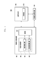
- FIG. 1 is a diagram schematically illustrating a configuration of an electronic pen input position detection apparatus using a C-type touch screen panel (TSP) according to an exemplary embodiment of the present invention.
- TSP C-type touch screen panel
- an input position detection apparatus 100 of the present invention may include a controller 160, a power unit 130, and a touch screen unit 140.
- the controller 160 may include a storage 170
- the touch screen unit 140 may include a touch sensor 145 which includes a receiving unit 141 and a transmission unit 143, and a filter 150.
- the input position detection apparatus 100 of the present invention may be used as a portion of the various products by combining with the peripheral devices those are not described herein or as a finished product itself.
- it may be used in a portable terminal such as a smart phone, a slate PC, and a tablet PC by coupling to a wireless communication unit, and may be used as a configuration element of a TV, a desktop, and a lab top.
- a portable terminal such as a smart phone, a slate PC, and a tablet PC by coupling to a wireless communication unit
- it may also be used as an electronic writing instrument itself receiving an electronic pen input. In other words, it may be used in all electronic devices that are equipped with the touch screen 140.
- the power supply unit 130 supplies a power to each configuration of an input position detection apparatus 100 which requires a power supply and, in particularly, supplies a power so that the transmission unit 143 of the touch sensor 145 may form an electric field.
- the touch sensor 145 When a user inputs a finger touch input or an electronic pen input on a touch screen, the touch sensor 145 outputs an electric signal detected from its input position to a controller 160.
- a transmission unit 143 is supplied with an electricity from a power supply unit 130 to form an electric field, and a change in the electric field causes generation of electric signals during operation.
- the electric signal serves as a standard for determining whether the TSP is touched. That is, a device can determine whether the TSP is touched by sensing a change of the electric signal, as explain in detail later.
- the transmission unit 143 transmits the electric signal to the receiving unit 141.
- the electric signal output from the transmission unit 143 is defined as an internal signal wherein the internal signal refers to a signal transmitted from the transmission unit 143.
- the receiving unit 141 receives the electric signal which is generated based on the change of the electric field formed by the transmission unit 141.
- the receiving unit 141 may receive the electric signal through the electric field formed by the external source of the input position detection apparatus 100.
- the electric signal received from the external source by the receiving unit is named as an external signal. That is, among electric signals received at the receiving unit 143, an electric signal from transmission unit 143 is an internal signal, and an electric signal from electronic pen is an external signal.
- the present invention uses these signal changes. The present invention attempts achieve recognizing position (location) of touch inputs without adding an extra magnetic sheet or extra sensor dedicated to the electronic pen.
- the filter 150 performs a function of classifying a plurality of electrical signals received by the receiving unit 141 according to the frequency. Since the receiving unit 141 receives not only the signal (i.e., internal signal) transmitted by the transmission unit 143 but also the signal transmitted from the external source (i.e., external signal) of the input position detection apparatus 100, the input position and the input method of each signal may be identified by classifying the detected signal when the controller detects a plurality of signals.
- the signals classified through the filter 150 according to the frequency of a plurality of signals received by the receiving unit 141 enables the controller 160 to distinguish whether the input is the finger touch input or the electronic pen input, or to determine whether the input is performed by the electronic pen input as explained in details later.
- the filter 150 transmits the electric signal to the transmission unit 143 in response to the power supply from the power supply unit 130. That is, the filter 150 filters a signal having a specific frequency using the power from the power supply unit 130.
- the controller 160 controls the signal processing and the power supply operation between each element of the input position detection apparatus 100 in order to detect the coordinates of input position according to an exemplary embodiment of the present invention.
- the controller 160 determines the type of input method and the input position on the touch screen based on the electric signal detected on the touch sensor 145.
- the controller 160 detects the finger touch input by the change of the strength of the electric signal received at the receiving unit 141.
- the strength of the internal signal remains constant as the strength of the power supplied to the transmission unit 143 from the power supply unit 130 through the filter 150 has a preset value according to the control of the controller 160.
- the uniform electric field formed between the transmission unit 143 and the receiving unit 141 is partially leaking through the finger. That is, a small amount of electrical charges are drawn to the point of contact. Circuits located at each corner of the panel measure the charge and send the information to the controller via the receiving unit 141 for processing.
- the strength of the electric signal received by the receiving unit 141 becomes less in comparison with a situation where a finger touch is not inputted.
- the controller may determine that the finger touch input has been performed based on a drop in the strength information of the electric signal.
- the controller 160 may determine the coordinates where user inputs the finger touch by detecting the position of the receiving unit 141 where the strength of the electric signal of the receiving unit 141 becomes less than the internal signal.
- the transmission unit 141 and the receiving unit 143 may configure a grid type touch sensor on the touch sensor 145 so that the controller 160 may know the input coordinates based on the grip type coordinate system.
- the receiving unit 141 corresponds to a plurality of sensor lines of horizontal axis which configures the grid type touch sensor
- the transmission unit 143 corresponds to a plurality of sensor lines of vertical axis which configures the grid type touch sensor.
- the controller 160 may determine which axes of the horizontal axis and the vertical axis to use as the receiving unit 141 or the transmission unit 143.
- the controller 160 may control the transmission unit 143 to be functioned as the receiving unit 141, and also, the controller 160 may control the receiving unit 141 to be functioned as the transmission unit 143.
- the controller 160 may determine that the finger touch inputs exist on a plurality of points. In addition, when the controller 160 detects that the strength of the electric signal is sequentially less than the strength of the internal signal, the controller 160 may determine a flick motion wherein the movement speed of the touch position is greater than the preset critical speed, and a drag motion, wherein the movement speed of the touch position is less than the preset critical speed.
- the touch input detection of the present invention generally uses a capacitive overlay touch sensor.
- the configuration of the apparatus for detecting the touch input detection according to the teachings of the present invention does not exclude the cases which include a touch sensor such as a resistive overlay and an infrared beam, or a pressure sensor.
- the storage 170 may be included to the controller 160; however, may be manufactured in a separate configuration.
- the storage 170 may store a data or the applications and the algorithms corresponding to the various basic operating systems and various user functions which are necessary in order to operate the input position detection apparatus 100.
- the storage 170 stores a program for adjusting a signal detecting frequency. For instance, it can increase the signal detecting frequency inside the proximate area and decrease the signal detecting frequency outside the proximate area.
- the input position detection apparatus 100 of the present invention does not limit the input method to the finger touch input as described above.
- the user may possibly use both an active and a passive stylus pen (or touch input) to the apparatus of the present invention.
- the active electronic pen is an electronic pen operating by transmitting the signal to the apparatus by the electronic pen, which uses the electromagnetic induction, and the passive stylus pen or non-active pen includes a finger input.
- FIG. 2 A detailed description for the active pen introduced in the present invention will be described in the description of FIG. 2 .
- FIG. 2 illustrates each element of an input position detection apparatus 100 described above according to an exemplary embodiment of the present invention.
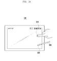
- FIG. 3A is a diagram illustrating the finger touch input and the electronic pen input according to an exemplary embodiment of the present invention.
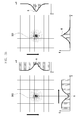
- FIG. 3B is a diagram illustrating a strength difference of a signal between a finger touch input and an electronic pen input which are the input methods according to an exemplary embodiment of the present invention.
- the touch sensor 145 includes the grid type touch sensor where a plurality of a horizontal sensor lines crosses at right angle to a plurality of a vertical sensor lines.
- the receiving unit 141 is arranged in the horizontal axis
- the transmission unit 143 is arranged in the vertical axis.
- the controller 160 may control to change the operation of the transmission unit 143 to the receiving unit 141, or change the operation of the receiving unit 141 to the transmission unit 143 by using a switch.
- the controller 160 may selectively detect the finger touch input and the electronic pen input according to the user's setting. When the controller 160 detects only the electronic pen input as specified in the user's setting, all sensor lines configuring the touch sensor can function as the receiving unit 141.
- the touch sensor 145 comprises the receiving unit 141 and transmission unit 143, but it is not limited thereto.
- the receiving unit 141 and transmission unit 143 can be disposed at a separate module.
- the controller 160 controls the process in which a power supplied by power supply unit 130 is supplied to the filter 150. Then, the filter 150 uses the power to generate electric signal of a preset frequency and supplies the generated electric signal to the transmission unit 143. A uniform electric field is formed between the transmission unit 143 and the receiving unit 141 through this process. Here, the transmission unit 143 transmits the electric signal to the receiving unit 141. The electric signal maintains a preset value of constant strength of electrical charges prior to the finger touch. If the finger touch input 310 is generated in such state, a charge leakage or electric charge to be dropped at the point of contact.
- the power supply unit 130 supplies the power to the vertical sensor line and the horizontal sensor line by using the switch, which enables the controller 160 to check for the strength of the charge for each axis in real time to detect whether the charge leakage or drop occurs.
- the controller 160 may determine that the finger touch input 310 has generated.
- the controller 160 may detect the input position by verifying the position where the strength of the electric signal is reduced by the finger touch input 310 based on the coordinate position of the transmission unit 143 and the receiving unit 141 configuring the grid type touch sensor. That is, circuits located at each corner of the panel measure the charge drop and send the information to the controller for processing which in turn determines the X and Y coordinate of the touch activation.
- the controller 160 may also recognize the occurrence of the finger touch inputs 310 and their input positions in the same manner. Meanwhile, the controller 160 may recognize the occurrence of the passive stylus pen input and detect its input position in the same manner. The controller 160 performs the detection operation, even though the finger touch input 310 and the input of the passive stylus pen input occur together in the input position detection apparatus 100.
- the electronic pen 200 of the present invention is an active electronic pen which emits an electric field. Since the position detection apparatus 100 of the present invention is not equipped with a magnetic sheet which is used in conjunction with the active electronic pen 200 of the present invention and the active electronic pen of the present invention includes a separate power supply unit for generating the electric field. That is, according to the present disclosure, the active electronic pen may comprise a built-in power supply.
- the electronic pen 200 forms the electric field between the receiving unit 141 of the position detection apparatus 100.
- the electronic pen 200 generates an electric signal using the electric field and transmits it to the receiving unit 141. That is, the change of the electric field generates electric signals.
- the controller 160 controls the filter 150 so that the electric signal may have a value of a specific frequency.
- the electric signal received by the receiving unit 141 from the transmission unit 143 maintains a preset constant magnitude of peak value.
- the receiving unit 141 receives the internal electric signal of the position detection apparatus 100 while maintaining the constant magnitude of peak value.
- both of the transmission unit 143 and electronic pen 200 transmit the electric signal to the receiving unit 141.
- the receiving unit 141 receives the electric signal from the electronic pen 200.
- the electric pen 200 can be self-powered by a built-in power supply unit or powered by an external power supply.
- the external power can be supplied through a USB port of a computer, RFID, or NFC.
- the electronic pen in the present invention comprises RF transmitter and antenna.
- the RF transmitter generates E-field and the antenna radiates the generated E-field.
- the electronic pen can comprises pen point, pressure sensor, power-supply unit and button. Therefore, the receiving unit 141 receives both the electric signal (internal signal) transmitted by the transmission unit 143 and the electric signal (external signal) transmitted by the electronic pen 200.
- the controller 160 may know the occurrence of a plurality of the electronic pen inputs 320 and a plurality of input positions in the same manner even though when there is a plurality of electronic pen inputs 320.
- the controller 160 may detect each input by detecting the strength of the signal received by the receiving unit 141.
- the controller 160 determines that the finger touch input 310 exists in the point.
- the controller 160 determines that the electronic pen input 320 exists in the point.
- the controller 160 may detect each input and their input positions/locations. Meanwhile, when the strength of the internal signal transmitted by the transmission unit 143 is identical to the strength of the electrical signal received by the receiving unit 141, the controller 160 can regard that neither the finger touch input 310 nor the electronic pen input 320 occurs.
- the controller 160 may control the functions of the receiving unit 141 and the transmission unit 143 configuring the grid type touch sensor.
- the controller 160 may selectively detect the finger touch input 310 and the electronic pen input 320 according to the user's setting.
- the sensor line configuring the touch sensor may function only as the receiving unit 141.
- the internal signal transmitted by the transmission unit 143 does not exist because there is no sensor line serving as the transmission unit 141. Therefore, the controller may detect the input position when the receiving unit 141 receives the electric signal which is stronger than the preset strength, instead of performing the procedure of comparing the strength of the internal signal and the strength of the signal received by the receiving unit 141.
- FIG. 3B is a diagram illustrating the difference of the strength of the signal receiving by the receiving unit 141 according to the finger touch input 310 or the electronic pen input 320 according to the exemplary embodiment of the present invention.
- the left side diagram and the right side diagram of FIG. 3B respectively illustrate, in the bar graph, the strength of the electric signal received by the receiving unit 141 against to the y axis of the touch sensor on the right side of grid type touch sensor, and the strength of the electric signal received by the receiving unit 141 against to x axis of the touch sensor on the bottom of the grid type touch sensor.
- the maximum value of the bar graph represents the strength of internal signal, in case the finger touch input 310 occur, generated by the transmission unit 143.
- the minimum value of the bar graph represents the strength of internal signal, in case the electronic pen input 320 occur, generated by the transmission unit 143.
- the controller 160 performs the detection operation of the electric signal in sequence along with the line to be the transmission 143 and the receiving unit 141 configuring the grid type touch sensor as the horizontal axis and the vertical axis respectively.
- the controller 160 controls first line of the transmission unit 143 to transmit the internal signal to the lines of receiving unit 141 in sequence in uniform strength.
- the controller 160 controls second line of the transmission unit 143 to transmit the internal signal to the lines of receiving unit 141 in sequence in uniform strength.
- the lines of receiving unit 141 interacts the lines of transmission unit 143 at a right angle.
- the controller 160 may know the strength of the signal of each touch sensor coordinate by detecting the strength of the signal of x-axis and y-axis of the grid type touch sensor.
- the left diagram of FIG. 3B illustrates the strength of the electric signal receiving by the receiving unit 141 from the point (point A) where the finger touch input 310 is generated and its periphery when there is the finger touch input 310.
- the controller 160 detects the electric signal having the strength value which is less than the strength of the internal signal as getting close to a corresponding point (point A) upon the occurrence of the finger touch input 310.
- the right diagram of FIG. 3B illustrates the strength of the electric signal receiving by the receiving unit 141 from the point (point B) where the electronic pen input 320 is generated and its periphery when there is the electronic pen input 320.
- the controller 160 may detect the strength of the signal in which the strength of the existing internal signal and the external signal transmitted by the electronic pen 200 are added.
- the controller 160 detects the electric signal having the strength value which is greater than the strength of the internal signal as getting close to a corresponding point (point B) upon the occurrence of the electronic pen input 320.
- FIG. 4 is a flowchart illustrating the input position detection method according to an exemplary embodiment of the present invention.
- the controller 160 detects the strength of the signal received by the receiving unit 141 (410). This means the strength of the signal received by the receiving unit 141 and the strength of the internal signal is not same.
- the signal received by the receiving unit 141 includes the electric signal (internal signal) transmitting to the receiving unit 141 by the transmission unit 143 and the electric signal (external signal) transmitting to the receiving unit 141 by the electronic pen 200.
- the receiving unit 141 may receive the internal signal and the external signal individually or may receive both signals together from the transmission unit 143 and the electronic pen 200.
- the controller 160 compares the strength of the signal received by the receiving unit 141 and the strength of the internal signal (420). When the strength of the received signal is lesser than the strength of the internal signal, the controller 160 recognizes the finger touch input 310 and detects the input coordinate (427). On the contrary to this, when the strength of the received signal is greater than the strength of the internal signal, the controller 160 recognizes the electronic pen input 320 and detects the input coordinate (430).
- FIG. 2 illustrates a configuration that a receiving unit 141 and a transmission unit 143 are arranged in a line type.
- the signal transmitted from the transmission unit 143 may be received by the receiving unit 141 through a plurality of sensing lines.
- the receiving unit 141 may selectively or sequentially detect the signal transmitted through the plurality of sensing lines by using a switch.
- the transmission unit 143 may transmit a desired frequency signal only, or the receiving unit 141 may receive a desired frequency signal only.
- the receiving unit 141 detects a signal for a specific position, it can set a proximate area around the specific position where the signal is detected. It can also differentiate the operations of signal detection for the inside of the proximate area and the outside of the proximate area, respectively.
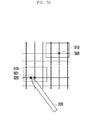
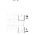
- FIGS. 5A and 5B are diagrams illustrating a setting of a proximate area in an input position according to an exemplary embodiment of the present invention.
- FIG. 6 is a flow chart illustrating an operation of signal detection in the inside of the proximate area and the outside of the proximate area according to an exemplary embodiment of the present invention.
- FIGS. 5A and 5B illustrate a plurality of sensor lines arranged with the horizontal axis and the vertical axis.
- Each sensor line can be connected to the receiving unit 141 and the transmission unit 143 through a switch and a filter.
- the sensor lines of the horizontal axis are indicated as R0 to R9
- the sensor lines of the vertical axis are indicated as C0 to C9.
- the number of the sensor lines of the horizontal axis and the vertical axis is 10, but it is not limited thereto.
- the controller 160 determines whether the input position is detected (610). Even when inputs are detected in a plurality of positions, in the adjacent detection places, an input position can be determined by the position close to a halfway point among the positions where the signal is detected or by the position where a signal having the strongest strength is detected. For example, the controller can determine that an input is occurred in the point 510 corresponding to the sensor line of the horizontal axis R6 and the sensor line of the vertical axis C5. In this case, the point 510 may be indicated as (R6, C5) as illustrated in FIG. 5A .
- the controller 160 sets a proximate area around the input position when the input position is detected (620). For example, two sensor lines adjacent to the input position may be set as the proximate area respectively. That is, the area corresponding to the sensor lines of the horizontal axis R4 to R8 and the sensor lines of the vertical axis C3 to C7 may be set as the proximate area. As an exemplary embodiment of the present invention, FIG. 5A illustrates the proximate area 520 of input position 510.
- the proximate area can be determined in consideration of a movement direction of the input position. For example, as shown in FIG. 5B , a broader proximate area 550 can be set in accordance with the movement direction of the input position.
- the controller determines that an input occurs in the point 510, the input can be detected in another place which is not the point 510. In this case, the direction of the input position can be determined in consideration of the previous detection and the next detection.
- FIG. 5B illustrates that the controller determines that a new input position occurs in (R5, C6). If the new input position is the point 530, a user input was moved from the point 510 to the point 530.
- the controller can set the broader proximate area 550 than the proximate area 540 when setting the proximate area for the point 530 as shown in FIG 5B . That is, the proximate area can be two sensor lines adjacent to the input positions in case of not considering the movement direction. On the other hand, the proximate area can be three sensor lines adjacent to the input positions in case of considering the movement direction or an estimated movement path.
- FIG. 5B illustrates that the controller sets the proximate area 540 for the point 530 in case of not considering the movement direction of the input position.
- FIG. 5B illustrates that the controller sets the proximate area 550 for the point 530 in consideration of estimated movement path of the input position.
- FIG. 5B illustrates that one additional sensor line is added for the movement direction of the input position, but it is not limited thereto. For example, two additional sensor lines can be added. Meanwhile, it can be configured in such a manner that the number of sensor lines positioned in the opposite side of the movement direction of the input position may be decreased.
- the controller 160 may increase the detection frequency with respect to the inside of the proximate area (630). For example, when the touch sensor 145 includes a plurality of sensing lines, the sensing period of the sensing line inside the proximate area may be decreased. Accordingly, the detection speed for the input position may be increased at the inside of the proximate area.
- the controller 160 may decrease the detection frequency with respect to the outside of the proximate area (640). For example, when the touch sensor 145 includes a plurality of sensing lines, the sensing period of the sensing line outside the proximate area may be increased, or alternatively, the sensing of some of the sensing lines outside the proximate area may be omitted. For instance, in a state that the proximate area is not set, the input can be detected in such a manner that all sensing lines are detected once, then all sensing lines are detected once again.
- the input can be detected in such a manner that the sensing line outside the proximate area is detected once after all sensing lines inside the proximate area are detected three times.
- the omitting of sensing of some of the sensing lines outside the proximate area may include sensing one line only out of adjacent two lines. Meanwhile, when two or more inputs which are not adjacent each other exist, the remaining area except the inside of the proximate area for each input position can be determined as the outside of the proximate area.
- the controller may detect the input as described above based on a preset proximate area until detecting the change of the input position.
- the controller may increase detection frequency in the inside and the outside of the proximate area respectively.
- the controller determines again whether the input position is detected after a predetermined time is elapsed (650). In this case, when the input position is not detected, the controller cancels the setting of the proximate area and detects the input position in a state that the proximate area does not exist (660).
- the controller may determine whether the input position is changed (670). When the input position is not changed, sensing is performed based on the preset proximate area. On the other hand, when the input position is changed, the proximate area is set based on the new input position and the input position is detected based on the newly set proximate area.
- An electronic pen position detection apparatus and a method using a C-type touch screen panel (TSP) enables a manufacturer to store a cost in manufacturing an input apparatus by supporting an input method by a finger touch and an electronic pen in one input apparatus.
- TSP C-type touch screen panel
- the above-described methods according to the present invention can be implemented in hardware, firmware or as software or computer code that can be stored in a recording medium such as a CD ROM, an RAM, a floppy disk, a hard disk, or a magneto-optical disk or computer code downloaded over a network originally stored on a remote recording medium or a non-transitory machine readable medium and to be stored on a local recording medium, so that the methods described herein can be rendered in such software that is stored on the recording medium using a general purpose computer, or a special processor or in programmable or dedicated hardware, such as an ASIC or FPGA.
- a recording medium such as a CD ROM, an RAM, a floppy disk, a hard disk, or a magneto-optical disk or computer code downloaded over a network originally stored on a remote recording medium or a non-transitory machine readable medium and to be stored on a local recording medium, so that the methods described herein can be rendered in such software that is stored on the recording medium using a
- the computer, the processor, microprocessor controller or the programmable hardware include memory components, e.g., RAM, ROM, Flash, etc. that may store or receive software or computer code that when accessed and executed by the computer, processor or hardware implement the processing methods described herein.
- memory components e.g., RAM, ROM, Flash, etc.
- the execution of the code transforms the general purpose computer into a special purpose computer for executing the processing shown herein.
Landscapes
- Engineering & Computer Science (AREA)
- General Engineering & Computer Science (AREA)
- Theoretical Computer Science (AREA)
- Physics & Mathematics (AREA)
- Human Computer Interaction (AREA)
- General Physics & Mathematics (AREA)
- Electromagnetism (AREA)
- Position Input By Displaying (AREA)
- User Interface Of Digital Computer (AREA)
Applications Claiming Priority (1)
| Application Number | Priority Date | Filing Date | Title |
|---|---|---|---|
| KR1020120083957A KR20140017255A (ko) | 2012-07-31 | 2012-07-31 | C―type tsp을 이용한 전자펜 입력 인식 장치 및 방법 |
Publications (2)
| Publication Number | Publication Date |
|---|---|
| EP2693313A2 true EP2693313A2 (fr) | 2014-02-05 |
| EP2693313A3 EP2693313A3 (fr) | 2017-08-23 |
Family
ID=48917372
Family Applications (1)
| Application Number | Title | Priority Date | Filing Date |
|---|---|---|---|
| EP13178612.1A Withdrawn EP2693313A3 (fr) | 2012-07-31 | 2013-07-30 | Appareil et procédé de reconnaissance d'entrée de stylo électronique utilisant un panneau d'écran tactile de type capacitif (TSP) |
Country Status (4)
| Country | Link |
|---|---|
| US (1) | US20140035848A1 (fr) |
| EP (1) | EP2693313A3 (fr) |
| KR (1) | KR20140017255A (fr) |
| CN (1) | CN103576981B (fr) |
Cited By (1)
| Publication number | Priority date | Publication date | Assignee | Title |
|---|---|---|---|---|
| CN104795042A (zh) * | 2015-05-08 | 2015-07-22 | 厦门天马微电子有限公司 | 一种触控驱动方法、系统、驱动模块和显示装置 |
Families Citing this family (10)
| Publication number | Priority date | Publication date | Assignee | Title |
|---|---|---|---|---|
| JP2015079485A (ja) * | 2013-09-11 | 2015-04-23 | 株式会社リコー | 座標入力システム、座標入力装置、座標入力方法及びプログラム |
| KR102252543B1 (ko) * | 2014-09-12 | 2021-05-17 | 엘지이노텍 주식회사 | 터치 디바이스, 터치 펜 및 터치 패널 |
| CN112181175B (zh) * | 2015-04-20 | 2024-05-31 | 株式会社和冠 | 传感器控制器、主动式触控笔及使用了它们的方法 |
| US20170270446A1 (en) * | 2015-05-01 | 2017-09-21 | 360 Yield Center, Llc | Agronomic systems, methods and apparatuses for determining yield limits |
| CN105677078A (zh) * | 2015-12-25 | 2016-06-15 | 惠州Tcl移动通信有限公司 | 移动终端及其自定义快捷键的方法 |
| US10073548B2 (en) * | 2016-11-08 | 2018-09-11 | Wacom Co., Ltd. | Stylus having variable transmit signal strength, and sensor for detecting such stylus |
| CN107607824A (zh) * | 2017-07-20 | 2018-01-19 | 武汉科技大学 | 一种电容/磁笔平板电子设备的自动测试机器人系统 |
| CN109521893B (zh) * | 2018-10-17 | 2022-11-25 | 京东方科技集团股份有限公司 | 触控笔、触控面板、触控感测系统及其控制方法 |
| KR102781964B1 (ko) * | 2019-07-30 | 2025-03-18 | 삼성전자주식회사 | 스타일러스 펜에 의한 제스처를 확인하는 전자 장치 및 그 동작 방법 |
| CN114637422A (zh) * | 2022-03-07 | 2022-06-17 | Oppo广东移动通信有限公司 | 防误触方法、装置、电子设备及计算机可读介质 |
Family Cites Families (14)
| Publication number | Priority date | Publication date | Assignee | Title |
|---|---|---|---|---|
| TW274598B (en) * | 1994-11-15 | 1996-04-21 | Alps Electric Co Ltd | Coordinate input device for pen of finger tip |
| US5945980A (en) * | 1997-11-14 | 1999-08-31 | Logitech, Inc. | Touchpad with active plane for pen detection |
| GB2428306B (en) * | 2005-07-08 | 2007-09-26 | Harald Philipp | Two-dimensional capacitive position sensor |
| WO2007129085A2 (fr) * | 2006-05-09 | 2007-11-15 | Sensopad Limited | Arrangement de navigation pour dispositif électronique |
| US8525799B1 (en) * | 2007-04-24 | 2013-09-03 | Cypress Semiconductor Conductor | Detecting multiple simultaneous touches on a touch-sensor device |
| US20100006350A1 (en) * | 2008-07-11 | 2010-01-14 | Elias John G | Stylus Adapted For Low Resolution Touch Sensor Panels |
| US9069405B2 (en) * | 2009-07-28 | 2015-06-30 | Cypress Semiconductor Corporation | Dynamic mode switching for fast touch response |
| US8723825B2 (en) * | 2009-07-28 | 2014-05-13 | Cypress Semiconductor Corporation | Predictive touch surface scanning |
| KR101073309B1 (ko) * | 2009-11-24 | 2011-10-12 | 삼성모바일디스플레이주식회사 | 터치 스크린 시스템 및 그 구동방법 |
| US8363034B2 (en) * | 2010-04-14 | 2013-01-29 | Panasonic Corporation | Touch panel device |
| JP2011257831A (ja) * | 2010-06-07 | 2011-12-22 | Panasonic Corp | タッチパネル装置 |
| WO2012039837A1 (fr) * | 2010-09-22 | 2012-03-29 | Cypress Semiconductor Corporation | Stylet capacitif destiné à un écran tactile |
| US20130050132A1 (en) * | 2011-08-26 | 2013-02-28 | Analog Devices, Inc. | Techniques for capacitive touch screen control |
| US8797287B2 (en) * | 2011-10-28 | 2014-08-05 | Atmel Corporation | Selective scan of touch-sensitive area for passive or active touch or proximity input |
-
2012
- 2012-07-31 KR KR1020120083957A patent/KR20140017255A/ko not_active Withdrawn
-
2013
- 2013-07-29 US US13/952,884 patent/US20140035848A1/en not_active Abandoned
- 2013-07-30 EP EP13178612.1A patent/EP2693313A3/fr not_active Withdrawn
- 2013-07-31 CN CN201310328898.0A patent/CN103576981B/zh not_active Expired - Fee Related
Non-Patent Citations (1)
| Title |
|---|
| None |
Cited By (2)
| Publication number | Priority date | Publication date | Assignee | Title |
|---|---|---|---|---|
| CN104795042A (zh) * | 2015-05-08 | 2015-07-22 | 厦门天马微电子有限公司 | 一种触控驱动方法、系统、驱动模块和显示装置 |
| CN104795042B (zh) * | 2015-05-08 | 2017-11-21 | 厦门天马微电子有限公司 | 一种触控驱动方法、系统、驱动模块和显示装置 |
Also Published As
| Publication number | Publication date |
|---|---|
| KR20140017255A (ko) | 2014-02-11 |
| CN103576981A (zh) | 2014-02-12 |
| US20140035848A1 (en) | 2014-02-06 |
| CN103576981B (zh) | 2018-06-01 |
| EP2693313A3 (fr) | 2017-08-23 |
Similar Documents
| Publication | Publication Date | Title |
|---|---|---|
| EP2693313A2 (fr) | Appareil et procédé de reconnaissance d'entrée de stylo électronique utilisant un panneau d'écran tactile de type capacitif (TSP) | |
| US10649552B2 (en) | Input method and electronic device using pen input device | |
| US9977529B2 (en) | Method for switching digitizer mode | |
| CN102141877B (zh) | 使用全息图的用户界面和用于该用户界面的方法 | |
| CN105786239B (zh) | 具有电感器的笔 | |
| CN106155409B (zh) | 用于模式变化的电容性度量处理 | |
| KR101913817B1 (ko) | 터치스크린 입력 처리 방법 및 장치 | |
| US9582127B2 (en) | Large feature biometrics using capacitive touchscreens | |
| WO2014160425A1 (fr) | Détection de proximité | |
| US9760277B2 (en) | Electronic device and method for detecting proximity input and touch input | |
| KR102334521B1 (ko) | 전자 장치 및 이의 입력 처리 방법 | |
| US9244608B2 (en) | Method and system for gesture identification | |
| CN106462312B (zh) | 检测触摸输入的方法、用于感测触摸输入的设备以及用于输入触摸输入的设备 | |
| US9569029B2 (en) | Baseline management with large input object detection | |
| CN108459818A (zh) | 控制屏幕解锁的方法和装置 | |
| KR101961786B1 (ko) | 터치스크린을 포함하는 단말을 이용한 마우스 기능의 제공 방법 및 장치 | |
| KR101360631B1 (ko) | 터치 제스처의 방향에 기초하여 디스플레이 기기를 원격제어 하기 위한 터치 감지 시스템 및 방법 그리고 원격제어 시스템 및 방법 | |
| KR101863555B1 (ko) | 입력 인터페이스 장치 및 방법 | |
| CN112860098A (zh) | 电子设备 | |
| US9952709B2 (en) | Using hybrid signal for large input object rejection | |
| EP3317754B1 (fr) | Filtrage de position pour des événements d'élévation de terrain |
Legal Events
| Date | Code | Title | Description |
|---|---|---|---|
| AK | Designated contracting states |
Kind code of ref document: A2 Designated state(s): AL AT BE BG CH CY CZ DE DK EE ES FI FR GB GR HR HU IE IS IT LI LT LU LV MC MK MT NL NO PL PT RO RS SE SI SK SM TR |
|
| AX | Request for extension of the european patent |
Extension state: BA ME |
|
| PUAI | Public reference made under article 153(3) epc to a published international application that has entered the european phase |
Free format text: ORIGINAL CODE: 0009012 |
|
| PUAL | Search report despatched |
Free format text: ORIGINAL CODE: 0009013 |
|
| AK | Designated contracting states |
Kind code of ref document: A3 Designated state(s): AL AT BE BG CH CY CZ DE DK EE ES FI FR GB GR HR HU IE IS IT LI LT LU LV MC MK MT NL NO PL PT RO RS SE SI SK SM TR |
|
| AX | Request for extension of the european patent |
Extension state: BA ME |
|
| RIC1 | Information provided on ipc code assigned before grant |
Ipc: G06F 3/041 20060101AFI20170718BHEP Ipc: G06F 3/044 20060101ALI20170718BHEP Ipc: G06F 3/0354 20130101ALI20170718BHEP |
|
| STAA | Information on the status of an ep patent application or granted ep patent |
Free format text: STATUS: THE APPLICATION HAS BEEN PUBLISHED |
|
| STAA | Information on the status of an ep patent application or granted ep patent |
Free format text: STATUS: THE APPLICATION IS DEEMED TO BE WITHDRAWN |
|
| 18D | Application deemed to be withdrawn |
Effective date: 20180224 |