EP2693397A1 - Procédé et appareil de réduction du bruit dans un système d'imagerie - Google Patents
Procédé et appareil de réduction du bruit dans un système d'imagerie Download PDFInfo
- Publication number
- EP2693397A1 EP2693397A1 EP12461534.5A EP12461534A EP2693397A1 EP 2693397 A1 EP2693397 A1 EP 2693397A1 EP 12461534 A EP12461534 A EP 12461534A EP 2693397 A1 EP2693397 A1 EP 2693397A1
- Authority
- EP
- European Patent Office
- Prior art keywords
- images
- image
- morphological data
- correlation
- captured images
- Prior art date
- Legal status (The legal status is an assumption and is not a legal conclusion. Google has not performed a legal analysis and makes no representation as to the accuracy of the status listed.)
- Granted
Links
Images



Classifications
-
- G—PHYSICS
- G06—COMPUTING OR CALCULATING; COUNTING
- G06T—IMAGE DATA PROCESSING OR GENERATION, IN GENERAL
- G06T5/00—Image enhancement or restoration
- G06T5/70—Denoising; Smoothing
-
- G—PHYSICS
- G06—COMPUTING OR CALCULATING; COUNTING
- G06T—IMAGE DATA PROCESSING OR GENERATION, IN GENERAL
- G06T5/00—Image enhancement or restoration
- G06T5/50—Image enhancement or restoration using two or more images, e.g. averaging or subtraction
-
- G—PHYSICS
- G06—COMPUTING OR CALCULATING; COUNTING
- G06T—IMAGE DATA PROCESSING OR GENERATION, IN GENERAL
- G06T7/00—Image analysis
- G06T7/30—Determination of transform parameters for the alignment of images, i.e. image registration
- G06T7/33—Determination of transform parameters for the alignment of images, i.e. image registration using feature-based methods
- G06T7/337—Determination of transform parameters for the alignment of images, i.e. image registration using feature-based methods involving reference images or patches
-
- G—PHYSICS
- G06—COMPUTING OR CALCULATING; COUNTING
- G06T—IMAGE DATA PROCESSING OR GENERATION, IN GENERAL
- G06T2207/00—Indexing scheme for image analysis or image enhancement
- G06T2207/10—Image acquisition modality
- G06T2207/10072—Tomographic images
- G06T2207/10101—Optical tomography; Optical coherence tomography [OCT]
-
- G—PHYSICS
- G06—COMPUTING OR CALCULATING; COUNTING
- G06T—IMAGE DATA PROCESSING OR GENERATION, IN GENERAL
- G06T2207/00—Indexing scheme for image analysis or image enhancement
- G06T2207/20—Special algorithmic details
- G06T2207/20212—Image combination
- G06T2207/20216—Image averaging
Definitions
- the present invention relates to a method of noise and interference reduction in an imaging system. More particularly the present invention relates to image integration, for example, in optical coherence tomography (OCT) imaging systems.
- OCT optical coherence tomography
- Conventional OCT devices comprise means for scanning a light beam transversally across a target object, i.e. in one or two directions perpendicular to the direction of propagation of the light beam.
- a two or three-dimensional image of the internal sample structure can be generated from the resulting signal obtained from the scans.
- a one-dimensional signal recorded along the direction of the light beam is usually called "A scan”.
- a number of A-scans composed along a line substantially perpendicular to the light beam form a two-dimensional cross-section of the structure under test which is typically called a "B-scan".
- the coordinate system used when referring to OCT images defines the z axis as substantially parallel to the light beam used to perform the OCT scan.
- the axes denoted as x and y are perpendicular to the z axis and to each other.
- A-scans are taken along the z axis while B-scans can be located in any plane including the z axis.
- B-scans can be located in the "xz" and "yz" planes.
- Noise and other interference that can occur in OCT imaging systems are detrimental to the clarity of any resulting B-scans.
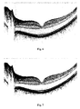
- An example of a distorted tomogram is shown in Fig. 6 .
- the first type of noise is related to the measurement sensitivity, the noise floor of the imaging camera and the exposure time. It can be visible as small bright or dark dots on a tomogram, even in areas representing empty space. This first type of noise is often referred to as additive noise.
- the second kind of noise is associated with the optical characteristics of the light source which is used in the image capturing device and, in particular, relates to the optical resolution of the light source. It manifests itself in images as structures of granular shape called speckles larger than the dots indicative of the first type of noise. This second type of noise is often referred to as multiplicative noise.
- a typical method is the so called multi-exposition method which consists in taking a set of images of the same object and integrating them so as to obtain an image of better quality. This method is well known in other fields of imaging, especially in astrophotography.
- This method can also be applied in OCT imaging, where a series of registered images i.e. B-scans, can be integrated by an image processing method.
- OCT imaging where a series of registered images i.e. B-scans, can be integrated by an image processing method.
- Such methods are used in some commercially available OCT devices, e.g. Spectralis, Heidelberg.
- the invention provides a method for integrating images relating to a plurality of captured images of a target region of an object.
- the method comprises following steps of:
- the integration performed may be of two or more of the corrected images only and not include an image relating to the reference morphological data or may be of an image relating the reference morphological data and at least one of the corrected images.
- the integration advantageously results in a single image of the target region with improved noise characteristics compared to the originally captured images.
- the method according to the first aspect of the invention solves a problem related to image integration.
- the method is more effective than those known in the art, because it is less susceptible to artifacts occurring in the images and is particularly suited to eye tomograms. As a consequence, it can be successfully applied to obtain OCT scans with high resolution and low noise.
- reference morphological data is obtained by selecting a reference image from captured images.
- the invention capturing images is realized by means of a tomography system applied to the eye and the captured images are B-scans.
- Preferably comparing the morphological data relating to the image with the reference morphological data further comprises determining a correlation value.
- a corrected image is generated only if the respective correlation value meets a predetermined threshold criterion.
- the method further comprises analyzing the morphology of the captured images to generate the morphological data.
- the method further comprises analyzing the morphological data to find morphological data that is unusable according to a predetermined criterion.
- images determined as having unusable morphological data are excluded from integration.
- each relative geometric transformation includes relative displacement measured as a triple representing horizontal and vertical translation and rotation ( ⁇ x i,j , ⁇ z i,j , ⁇ i,j ), while the transform operation comprises applying a geometric transformation based on said triple but with opposite sign.
- geometric transformation further includes scaling parameters.
- a cross-correlation procedure is applied to the morphological data of captured images and selection of reference image is based on the result of this correlation.
- Preferably reference image is the one that has maximum number of correlation values with other images that exceeds a predetermined limit value.
- Advantageously images are assigned consecutive indexes during capture and where in the case that more than one image has the maximum number of correlation values exceeding the predetermined limit the image selected is the one that has an index closest to the half of the total number of captured images.
- Preferably integrating includes any or all of taking a mean, median or weighted average of the corrected images.
- invention provides an imaging system comprising a processing unit, wherein processing unit is adapted to perform the method presented above.
- system further comprises image capturing means for capturing a series of images to be integrated.
- invention provides a machine readable medium carrying one or more machine readable instructions that upon execution by a processor cause a machine to perform a method presented above.
- a preferred embodiment of the invention relates to an OCT system dedicated to imaging the human eye.
- OCT system dedicated to imaging the human eye.
- the most significant features are layers which are anatomical structures inside the eye.
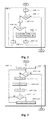
- a flow chart of a method for tomogram integration according to a first embodiment of the invention is presented in Fig. 1 .
- the process begins with STEP 1.1 in which morphological data, is used to find a best correlation (translation and/or rotation) between each pair of B-scans.
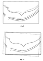
- Morphological data in this embodiment is simply layer data corresponding to captured B-scans. Correlated layers are shown separately in Fig. 8 and overlaid in Fig. 9 . As is clear from Fig.9 , there is a displacement between the layer boundaries identified in the first tomogram (shown with a solid line) and those from the second tomogram (shown with the dotted line).
- S denotes a number of tomograms taken during an topographic capture process which constitutes the set of tomograms to be integrated. Every tomogram in the set is assigned its own unique index from range ⁇ 0,
- Fig. 2 shows the steps performed at step 1.1 of the algorithm of figure 1 where i and j refer to indexes of B-scans which are to be processed. For each pair of i-th and j-th tomograms the following parameters are calculated:
- index i is initialized to 0. Then a first loop begins. A first loop continuation condition is evaluated in STEP 1.1.2 for index i. If the loop continuation condition i ⁇
- STEP 1.1.5 is performed in which values ( ⁇ x i,j , ⁇ z i,j , ⁇ i,j ,d i,j ) are calculated as a measure of the correlation between tomograms i and j .
- index j is incremented and STEP 1.1.4 is performed again.
- FIG. 3 A flow chart showing the steps of finding the best correlation as per step 1.1.5 is shown in Fig. 3 .
- D is the set of possible transformations.
- the transformations are typically translations and rotations.
- D is defined as follows: ⁇ x ⁇ ⁇ -50,50 ⁇ , ⁇ z ⁇ ⁇ -50,50 ⁇ and ⁇ ⁇ ⁇ -10,10 ⁇ .
- step 1.1.5.1 values to be determined by the subroutine ( ⁇ x i,j , ⁇ z i,j , ⁇ i,j ,d i,j ) are initialized to infinity. Then a first loop begins.
- STEP 1.1.5.2 a first loop termination condition is evaluated.
- Averaging applied to calculate dist and layerDist may be advantageously replaced with median or weighted average or any other measure of the fit between curves like for instance maximum.
- FIG. 11 An example of calculating the correlation value between two layer's boundaries is presented in Fig. 11 .
- the solid line represents the A k boundary and the dashed one the B k boundary.
- the vertical dotted lines indicate the left and right limits of calculation.
- the vertical lines with arrows represent the difference between the position of layers for a particular A-scan, i.e.
- A-scans taken into account may also be selected according to a predetermined pattern.
- the limit parameter is set as being equal to the value 2.
- the limit parameter is preferably calibrated or optimized either manually or automatically according the imaging application to which the process is being applied. Images which have the highest number of approved correlations compared among the set are determined as candidates for being a reference tomogram.
- a reference tomogram is selected to be a source of reference morphological data. If there is the only one candidate for the reference tomogram from STEP 1.2 that candidate is selected as the reference tomogram. Otherwise the selection is made of the tomogram from among the candidate reference tomograms which was taken nearest the middle of the sequence of captured images.
- the reference morphological data originating from the selected reference tomogram is used for two purposes. One is to define a common coordinate system for the integration process. The other is to calculate the dislocation of B-scans with respect to the reference morphological data and preferably determine which of them can be integrated. This operation is performed in step 1.4.
- reference morphological data are obtained simply by selection of one reference tomogram and extracting morphological data from it.
- the selection of the reference tomogram is based on the above described algorithm. However, different selection criteria may be used that utilizes the correlation data to find the most suitable candidate.
- a reference image can be obtained by averaging (calculating a mean or median) of several sets of morphological data.
- the reference image can be selected from the middle of the sequence of captured tomograms and morphological data based on that image used.
- a user may manually select which of the captured set of tomographs is to be used as a reference. It is also possible to use external morphological data obtained in a different measurement session or with different measurement equipment or even taken from available model (e.g. a computational model) of the object under test.
- available model e.g. a computational model
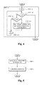
- Fig. 4 there is shown a flow-chart showing the steps performed in step 1.4 in comparing reference tomogram and the other tomograms.
- the comparison is aimed at finding shift ( ⁇ x i,j , ⁇ y i,j ) and rotation ( ⁇ i,j ) values that guarantee a best correlation (d i,j ) between reference tomogram and the other tomograms.
- additional best scaling (shrinking/expansion) parameters may be computed during the comparison.
- STEP 1.4 is very similar to step 1.1 and the same parameters are calculated - horizontal translation ( ⁇ x i,j ), vertical translation ( ⁇ z i,j ), and rotation ( ⁇ i,j ) values of the best correlation between the subject and reference tomograms and the best match found between two B-scans, measured as a maximal correlation value (d i,j ).
- step 1.4.2 loop duration condition is evaluated. If loop duration condition i ⁇
- is not met then STEP 1.4 terminates at STOP. Otherwise, condition i REF is evaluated. If it is not met then STEP 1.4.4 is executed.
- step 1.4.4 is the same as in step 1.1.5 - it is based on a calculation of dist and then acceptance from step 1.2 as described above, however, the limit parameter is different at this time and equal to 1 to denote a lower threshold for acceptance for integration.
- STEP 1.4.5 is executed in which index i incremented. If condition evaluated in STEP 1.4.3 is met the STEP 1.4.4 is not executed and flow goes directly to STEP 1.4.5. Next condition of STEP 1.4.2 is again evaluated.
- Fig. 6 presents a tomogram that suffers from noise
- Fig. 7 presents tomogram of the same object obtained after performing integration according to the method described herein.
- Execution of the method can be significantly speed-up if limit parameter has the same value in steps 1.1.5 and 1.4.1. Further speed up may be obtained if in STEP 1.4 correlations already counted in 1.1 are used. However, in some cases it may be preferable to use different possible transformation sets D in step 1.4 than in step 1.1.5.
- Fig. 8 shows an example of two tomograms of a retina with some layer boundaries.
- One of B-scans is drawn in dashed line and in this example is affected by the eye movement.
- Geometric distortion is apparent between the tomograms and is more visible after overlaying one on the other as shown in Fig. 9 .
- This geometric distortion can be corrected by suitable translation and/or rotation demonstrated in Fig. 10 as well as rescaling of a B-scan i.e. shrinking/expanding.
- the latter can be used to correct any kind of scanning distortions introduced by the imaging system, such as optical aberrations, nonlinearity of scanning devices (e.g. non-linear movement of a mirror deflecting a beam to be scanned over the object) as well as distortions introduced by a moving object during scanning.
- any other features visible on an image object can be used to provide morphological data on which to base correlation calculations.
- Steps 1.1.5 and 1.4.1 a different 'limit' value is used in Steps 1.1.5 and 1.4.1.
- an increase in computational efficiency can be achieved if the value used is the same for both.
- this step allowing this step to only be performed once and the result used for both selection of the reference and determining whether the image should be integrated.
- the determination of the best correlation in steps 1.1.5 and 1.4.1 is based on a 'brute-force' search algorithm.
- other optimization procedures for finding the best correlation could be applied, for example, a Hook-Jeeves optimization.
- the integration is based on layer detection only.
- the layer detection could be mixed with a pixel matching method.
- the above described method could be used to find an approximate correlation between features in the images and the pixel based data could be used to perform a fine tuning of the approximate correlation.
- methods esmbodying the present invention may be computer-implemented methods.
- the present invention extends to a program which, when executed by a computer or processor, causes the computer or processor to carry out any of the methods described hereinbefore.
- Such a program may be provided by itself or may be carried in, by or on a carrier medium.
- the carrier medium may be a storage medium or recording medium, in particular a computer-readable storage medium. Examples include a hard disk drive, DVD, or memory device.
- the carrier medium may also be a transmission medium such as a signal.
- a program embodying the present invention may be distributed, downloaded or uploaded in the form of a signal through a network including the Internet.
- the program may be non-transitory.
Landscapes
- Engineering & Computer Science (AREA)
- Physics & Mathematics (AREA)
- General Physics & Mathematics (AREA)
- Theoretical Computer Science (AREA)
- Computer Vision & Pattern Recognition (AREA)
- Eye Examination Apparatus (AREA)
- Investigating Or Analysing Materials By Optical Means (AREA)
Priority Applications (1)
| Application Number | Priority Date | Filing Date | Title |
|---|---|---|---|
| EP12461534.5A EP2693397B1 (fr) | 2012-07-30 | 2012-07-30 | Procédé et appareil de réduction du bruit dans un système d'imagerie |
Applications Claiming Priority (1)
| Application Number | Priority Date | Filing Date | Title |
|---|---|---|---|
| EP12461534.5A EP2693397B1 (fr) | 2012-07-30 | 2012-07-30 | Procédé et appareil de réduction du bruit dans un système d'imagerie |
Publications (2)
| Publication Number | Publication Date |
|---|---|
| EP2693397A1 true EP2693397A1 (fr) | 2014-02-05 |
| EP2693397B1 EP2693397B1 (fr) | 2017-09-06 |
Family
ID=46829685
Family Applications (1)
| Application Number | Title | Priority Date | Filing Date |
|---|---|---|---|
| EP12461534.5A Not-in-force EP2693397B1 (fr) | 2012-07-30 | 2012-07-30 | Procédé et appareil de réduction du bruit dans un système d'imagerie |
Country Status (1)
| Country | Link |
|---|---|
| EP (1) | EP2693397B1 (fr) |
Cited By (3)
| Publication number | Priority date | Publication date | Assignee | Title |
|---|---|---|---|---|
| WO2016108755A1 (fr) * | 2014-12-30 | 2016-07-07 | Agency For Science, Technology And Research | Procédé et appareil d'alignement d'une image en deux dimensions avec un axe prédéfini |
| EP3453314A1 (fr) | 2017-09-07 | 2019-03-13 | Canon Kabushiki Kaisha | Appareil de traitement d'image, procédé d'alignement et programme |
| US10803568B2 (en) | 2017-09-07 | 2020-10-13 | Canon Kabushiki Kaisha | Image processing apparatus, alignment method and storage medium |
-
2012
- 2012-07-30 EP EP12461534.5A patent/EP2693397B1/fr not_active Not-in-force
Non-Patent Citations (5)
| Title |
|---|
| B SANDER: "Enhanced optical coherence tomography imaging by multiple scan averaging", BRITISH JOURNAL OF OPHTHALMOLOGY, vol. 89, no. 2, 1 February 2005 (2005-02-01), pages 207 - 212, XP055044967, ISSN: 0007-1161, DOI: 10.1136/bjo.2004.045989 * |
| DAVID ALONSO-CANEIRO ET AL: "Speckle reduction in optical coherence tomography imaging by affine-motion image registration", JOURNAL OF BIOMEDICAL OPTICS, vol. 16, no. 11, November 2011 (2011-11-01), pages 116027-1 - 116027-5, XP055044973, ISSN: 1083-3668, DOI: 10.1117/1.3652713 * |
| FLORENCE ROSSANT ET AL: "Enhancement of Optical Coherence Tomography Images of the Retina by Normalization and Fusion", RADIOENGINEERING, vol. 17, no. 4, 1 December 2008 (2008-12-01), pages 86 - 90, XP055044994 * |
| MACIEJ SZKULMOWSKI ET AL: "Efficient reduction of speckle noise in Optical Coherence Tomography", OPTICS EXPRESS, vol. 20, no. 2, 6 January 2012 (2012-01-06), pages 1337, XP055044858, DOI: 10.1364/OE.20.001337 * |
| SZKULMOWSKI ET AL., OPTICS EXPRESS, vol. 20, no. 2, 2012, pages 1337 |
Cited By (4)
| Publication number | Priority date | Publication date | Assignee | Title |
|---|---|---|---|---|
| WO2016108755A1 (fr) * | 2014-12-30 | 2016-07-07 | Agency For Science, Technology And Research | Procédé et appareil d'alignement d'une image en deux dimensions avec un axe prédéfini |
| EP3453314A1 (fr) | 2017-09-07 | 2019-03-13 | Canon Kabushiki Kaisha | Appareil de traitement d'image, procédé d'alignement et programme |
| US10789721B2 (en) | 2017-09-07 | 2020-09-29 | Canon Kabushiki Kaisha | Image processing apparatus, alignment method and storage medium |
| US10803568B2 (en) | 2017-09-07 | 2020-10-13 | Canon Kabushiki Kaisha | Image processing apparatus, alignment method and storage medium |
Also Published As
| Publication number | Publication date |
|---|---|
| EP2693397B1 (fr) | 2017-09-06 |
Similar Documents
| Publication | Publication Date | Title |
|---|---|---|
| CN109345469B (zh) | 一种基于条件生成对抗网络的oct成像中散斑去噪方法 | |
| EP1788525B1 (fr) | Procédé d'imagerie radiographique pour la reconstruction tridimensionnelle, dispositif et programme d'ordinateur pour mettre en oeuvre ce procédé | |
| JP6039156B2 (ja) | 画像処理装置、画像処理方法、及びプログラム | |
| US8657440B2 (en) | Image processing apparatus and image processing method | |
| US9089280B2 (en) | Image processing apparatus, image processing method, and program storage medium | |
| CN103886576B (zh) | 一种腺体组织特征灰度检测方法及装置 | |
| CN108369737B (zh) | 使用启发式图搜索以快速且自动地分割分层图像 | |
| US10229494B2 (en) | Automated analysis of intravascular OCT image volumes | |
| EP2693397B1 (fr) | Procédé et appareil de réduction du bruit dans un système d'imagerie | |
| Naz et al. | Glaucoma detection in color fundus images using cup to disc ratio | |
| Zhang et al. | Self-supervised PSF-informed deep learning enables real-time deconvolution for optical coherence tomography | |
| US20150023471A1 (en) | Stereo x-ray tube based suppression of outside body high contrast objects | |
| KR100684301B1 (ko) | 화상처리장치 및 방법 | |
| GB2512697A (en) | Improvements in and relating to ophthalmoscopes | |
| Bandyopadhyay et al. | Bone contour tracing in digital X-ray images based on adaptive thresholding | |
| Niu et al. | Registration of SD-OCT en-face images with color fundus photographs based on local patch matching | |
| JP6949628B2 (ja) | 画像処理装置、光干渉断層撮像装置、画像処理方法、及びプログラム | |
| CN117942041A (zh) | 血管成像方法、装置、设备及存储介质 | |
| WO2014096835A1 (fr) | Améliorations apportées à des ophtalmoscopes et relatives à des ophtalmoscopes | |
| CN108720826A (zh) | 基于激光散斑的运动伤害预警方法 | |
| Flores et al. | Identifying precursory cancer lesions using temporal texture analysis | |
| KR102826133B1 (ko) | 품질 기반의 내시경 이미지 획득 방법 및 장치 | |
| JP6419249B2 (ja) | 画像処理装置、画像処理方法および画像処理プログラム | |
| JP6419115B2 (ja) | 画像処理装置、画像処理方法、及びプログラム | |
| JP2017070590A (ja) | 画像処理装置及びその制御方法、コンピュータプログラム |
Legal Events
| Date | Code | Title | Description |
|---|---|---|---|
| AK | Designated contracting states |
Kind code of ref document: A1 Designated state(s): AL AT BE BG CH CY CZ DE DK EE ES FI FR GB GR HR HU IE IS IT LI LT LU LV MC MK MT NL NO PL PT RO RS SE SI SK SM TR |
|
| AX | Request for extension of the european patent |
Extension state: BA ME |
|
| PUAI | Public reference made under article 153(3) epc to a published international application that has entered the european phase |
Free format text: ORIGINAL CODE: 0009012 |
|
| 17P | Request for examination filed |
Effective date: 20140702 |
|
| RBV | Designated contracting states (corrected) |
Designated state(s): AL AT BE BG CH CY CZ DE DK EE ES FI FR GB GR HR HU IE IS IT LI LT LU LV MC MK MT NL NO PL PT RO RS SE SI SK SM TR |
|
| RAP1 | Party data changed (applicant data changed or rights of an application transferred) |
Owner name: OPTOPOL TECHNOLOGY SP. Z O.O. |
|
| RAP1 | Party data changed (applicant data changed or rights of an application transferred) |
Owner name: CANON OPHTHALMIC TECHNOLOGIES SP. Z O. O. |
|
| 17Q | First examination report despatched |
Effective date: 20160105 |
|
| RAP1 | Party data changed (applicant data changed or rights of an application transferred) |
Owner name: CANON KABUSHIKI KAISHA |
|
| REG | Reference to a national code |
Ref country code: DE Ref legal event code: R079 Ref document number: 602012036878 Country of ref document: DE Free format text: PREVIOUS MAIN CLASS: G06T0005500000 Ipc: G06T0007330000 |
|
| GRAP | Despatch of communication of intention to grant a patent |
Free format text: ORIGINAL CODE: EPIDOSNIGR1 |
|
| RIC1 | Information provided on ipc code assigned before grant |
Ipc: G06T 5/00 20060101ALI20170203BHEP Ipc: G06T 7/33 20170101AFI20170203BHEP Ipc: G06T 5/50 20060101ALI20170203BHEP |
|
| INTG | Intention to grant announced |
Effective date: 20170310 |
|
| RIN1 | Information on inventor provided before grant (corrected) |
Inventor name: PIOTROWSKI, KRZYSZTOF Inventor name: PINTAL, LUKASZ Inventor name: CHALECKI, ARKADIUSZ |
|
| GRAS | Grant fee paid |
Free format text: ORIGINAL CODE: EPIDOSNIGR3 |
|
| GRAA | (expected) grant |
Free format text: ORIGINAL CODE: 0009210 |
|
| AK | Designated contracting states |
Kind code of ref document: B1 Designated state(s): AL AT BE BG CH CY CZ DE DK EE ES FI FR GB GR HR HU IE IS IT LI LT LU LV MC MK MT NL NO PL PT RO RS SE SI SK SM TR |
|
| REG | Reference to a national code |
Ref country code: GB Ref legal event code: FG4D |
|
| REG | Reference to a national code |
Ref country code: CH Ref legal event code: EP Ref country code: AT Ref legal event code: REF Ref document number: 926621 Country of ref document: AT Kind code of ref document: T Effective date: 20170915 |
|
| REG | Reference to a national code |
Ref country code: IE Ref legal event code: FG4D |
|
| REG | Reference to a national code |
Ref country code: DE Ref legal event code: R096 Ref document number: 602012036878 Country of ref document: DE |
|
| REG | Reference to a national code |
Ref country code: NL Ref legal event code: MP Effective date: 20170906 |
|
| REG | Reference to a national code |
Ref country code: DE Ref legal event code: R082 Ref document number: 602012036878 Country of ref document: DE Representative=s name: WESER & KOLLEGEN PATENTANWAELTE PARTMBB, DE Ref country code: DE Ref legal event code: R082 Ref document number: 602012036878 Country of ref document: DE Representative=s name: WESER & KOLLEGEN, DE |
|
| REG | Reference to a national code |
Ref country code: LT Ref legal event code: MG4D |
|
| PG25 | Lapsed in a contracting state [announced via postgrant information from national office to epo] |
Ref country code: HR Free format text: LAPSE BECAUSE OF FAILURE TO SUBMIT A TRANSLATION OF THE DESCRIPTION OR TO PAY THE FEE WITHIN THE PRESCRIBED TIME-LIMIT Effective date: 20170906 Ref country code: SE Free format text: LAPSE BECAUSE OF FAILURE TO SUBMIT A TRANSLATION OF THE DESCRIPTION OR TO PAY THE FEE WITHIN THE PRESCRIBED TIME-LIMIT Effective date: 20170906 Ref country code: FI Free format text: LAPSE BECAUSE OF FAILURE TO SUBMIT A TRANSLATION OF THE DESCRIPTION OR TO PAY THE FEE WITHIN THE PRESCRIBED TIME-LIMIT Effective date: 20170906 Ref country code: LT Free format text: LAPSE BECAUSE OF FAILURE TO SUBMIT A TRANSLATION OF THE DESCRIPTION OR TO PAY THE FEE WITHIN THE PRESCRIBED TIME-LIMIT Effective date: 20170906 Ref country code: NO Free format text: LAPSE BECAUSE OF FAILURE TO SUBMIT A TRANSLATION OF THE DESCRIPTION OR TO PAY THE FEE WITHIN THE PRESCRIBED TIME-LIMIT Effective date: 20171206 |
|
| REG | Reference to a national code |
Ref country code: AT Ref legal event code: MK05 Ref document number: 926621 Country of ref document: AT Kind code of ref document: T Effective date: 20170906 |
|
| PG25 | Lapsed in a contracting state [announced via postgrant information from national office to epo] |
Ref country code: BG Free format text: LAPSE BECAUSE OF FAILURE TO SUBMIT A TRANSLATION OF THE DESCRIPTION OR TO PAY THE FEE WITHIN THE PRESCRIBED TIME-LIMIT Effective date: 20171206 Ref country code: LV Free format text: LAPSE BECAUSE OF FAILURE TO SUBMIT A TRANSLATION OF THE DESCRIPTION OR TO PAY THE FEE WITHIN THE PRESCRIBED TIME-LIMIT Effective date: 20170906 Ref country code: RS Free format text: LAPSE BECAUSE OF FAILURE TO SUBMIT A TRANSLATION OF THE DESCRIPTION OR TO PAY THE FEE WITHIN THE PRESCRIBED TIME-LIMIT Effective date: 20170906 Ref country code: ES Free format text: LAPSE BECAUSE OF FAILURE TO SUBMIT A TRANSLATION OF THE DESCRIPTION OR TO PAY THE FEE WITHIN THE PRESCRIBED TIME-LIMIT Effective date: 20170906 Ref country code: GR Free format text: LAPSE BECAUSE OF FAILURE TO SUBMIT A TRANSLATION OF THE DESCRIPTION OR TO PAY THE FEE WITHIN THE PRESCRIBED TIME-LIMIT Effective date: 20171207 |
|
| PG25 | Lapsed in a contracting state [announced via postgrant information from national office to epo] |
Ref country code: NL Free format text: LAPSE BECAUSE OF FAILURE TO SUBMIT A TRANSLATION OF THE DESCRIPTION OR TO PAY THE FEE WITHIN THE PRESCRIBED TIME-LIMIT Effective date: 20170906 |
|
| PG25 | Lapsed in a contracting state [announced via postgrant information from national office to epo] |
Ref country code: RO Free format text: LAPSE BECAUSE OF FAILURE TO SUBMIT A TRANSLATION OF THE DESCRIPTION OR TO PAY THE FEE WITHIN THE PRESCRIBED TIME-LIMIT Effective date: 20170906 Ref country code: PL Free format text: LAPSE BECAUSE OF FAILURE TO SUBMIT A TRANSLATION OF THE DESCRIPTION OR TO PAY THE FEE WITHIN THE PRESCRIBED TIME-LIMIT Effective date: 20170906 Ref country code: CZ Free format text: LAPSE BECAUSE OF FAILURE TO SUBMIT A TRANSLATION OF THE DESCRIPTION OR TO PAY THE FEE WITHIN THE PRESCRIBED TIME-LIMIT Effective date: 20170906 |
|
| PG25 | Lapsed in a contracting state [announced via postgrant information from national office to epo] |
Ref country code: SK Free format text: LAPSE BECAUSE OF FAILURE TO SUBMIT A TRANSLATION OF THE DESCRIPTION OR TO PAY THE FEE WITHIN THE PRESCRIBED TIME-LIMIT Effective date: 20170906 Ref country code: IS Free format text: LAPSE BECAUSE OF FAILURE TO SUBMIT A TRANSLATION OF THE DESCRIPTION OR TO PAY THE FEE WITHIN THE PRESCRIBED TIME-LIMIT Effective date: 20180106 Ref country code: EE Free format text: LAPSE BECAUSE OF FAILURE TO SUBMIT A TRANSLATION OF THE DESCRIPTION OR TO PAY THE FEE WITHIN THE PRESCRIBED TIME-LIMIT Effective date: 20170906 Ref country code: IT Free format text: LAPSE BECAUSE OF FAILURE TO SUBMIT A TRANSLATION OF THE DESCRIPTION OR TO PAY THE FEE WITHIN THE PRESCRIBED TIME-LIMIT Effective date: 20170906 Ref country code: AT Free format text: LAPSE BECAUSE OF FAILURE TO SUBMIT A TRANSLATION OF THE DESCRIPTION OR TO PAY THE FEE WITHIN THE PRESCRIBED TIME-LIMIT Effective date: 20170906 Ref country code: SM Free format text: LAPSE BECAUSE OF FAILURE TO SUBMIT A TRANSLATION OF THE DESCRIPTION OR TO PAY THE FEE WITHIN THE PRESCRIBED TIME-LIMIT Effective date: 20170906 |
|
| REG | Reference to a national code |
Ref country code: DE Ref legal event code: R097 Ref document number: 602012036878 Country of ref document: DE |
|
| PLBE | No opposition filed within time limit |
Free format text: ORIGINAL CODE: 0009261 |
|
| STAA | Information on the status of an ep patent application or granted ep patent |
Free format text: STATUS: NO OPPOSITION FILED WITHIN TIME LIMIT |
|
| PG25 | Lapsed in a contracting state [announced via postgrant information from national office to epo] |
Ref country code: DK Free format text: LAPSE BECAUSE OF FAILURE TO SUBMIT A TRANSLATION OF THE DESCRIPTION OR TO PAY THE FEE WITHIN THE PRESCRIBED TIME-LIMIT Effective date: 20170906 |
|
| 26N | No opposition filed |
Effective date: 20180607 |
|
| PG25 | Lapsed in a contracting state [announced via postgrant information from national office to epo] |
Ref country code: SI Free format text: LAPSE BECAUSE OF FAILURE TO SUBMIT A TRANSLATION OF THE DESCRIPTION OR TO PAY THE FEE WITHIN THE PRESCRIBED TIME-LIMIT Effective date: 20170906 |
|
| REG | Reference to a national code |
Ref country code: CH Ref legal event code: PL |
|
| GBPC | Gb: european patent ceased through non-payment of renewal fee |
Effective date: 20180730 |
|
| PG25 | Lapsed in a contracting state [announced via postgrant information from national office to epo] |
Ref country code: LU Free format text: LAPSE BECAUSE OF NON-PAYMENT OF DUE FEES Effective date: 20180730 Ref country code: MC Free format text: LAPSE BECAUSE OF FAILURE TO SUBMIT A TRANSLATION OF THE DESCRIPTION OR TO PAY THE FEE WITHIN THE PRESCRIBED TIME-LIMIT Effective date: 20170906 |
|
| REG | Reference to a national code |
Ref country code: BE Ref legal event code: MM Effective date: 20180731 |
|
| PG25 | Lapsed in a contracting state [announced via postgrant information from national office to epo] |
Ref country code: CH Free format text: LAPSE BECAUSE OF NON-PAYMENT OF DUE FEES Effective date: 20180731 Ref country code: FR Free format text: LAPSE BECAUSE OF NON-PAYMENT OF DUE FEES Effective date: 20180731 Ref country code: GB Free format text: LAPSE BECAUSE OF NON-PAYMENT OF DUE FEES Effective date: 20180730 Ref country code: LI Free format text: LAPSE BECAUSE OF NON-PAYMENT OF DUE FEES Effective date: 20180731 |
|
| REG | Reference to a national code |
Ref country code: IE Ref legal event code: MM4A |
|
| PG25 | Lapsed in a contracting state [announced via postgrant information from national office to epo] |
Ref country code: BE Free format text: LAPSE BECAUSE OF NON-PAYMENT OF DUE FEES Effective date: 20180731 |
|
| PG25 | Lapsed in a contracting state [announced via postgrant information from national office to epo] |
Ref country code: IE Free format text: LAPSE BECAUSE OF NON-PAYMENT OF DUE FEES Effective date: 20180730 |
|
| PG25 | Lapsed in a contracting state [announced via postgrant information from national office to epo] |
Ref country code: MT Free format text: LAPSE BECAUSE OF NON-PAYMENT OF DUE FEES Effective date: 20180730 |
|
| PG25 | Lapsed in a contracting state [announced via postgrant information from national office to epo] |
Ref country code: TR Free format text: LAPSE BECAUSE OF FAILURE TO SUBMIT A TRANSLATION OF THE DESCRIPTION OR TO PAY THE FEE WITHIN THE PRESCRIBED TIME-LIMIT Effective date: 20170906 |
|
| PG25 | Lapsed in a contracting state [announced via postgrant information from national office to epo] |
Ref country code: HU Free format text: LAPSE BECAUSE OF FAILURE TO SUBMIT A TRANSLATION OF THE DESCRIPTION OR TO PAY THE FEE WITHIN THE PRESCRIBED TIME-LIMIT; INVALID AB INITIO Effective date: 20120730 Ref country code: PT Free format text: LAPSE BECAUSE OF FAILURE TO SUBMIT A TRANSLATION OF THE DESCRIPTION OR TO PAY THE FEE WITHIN THE PRESCRIBED TIME-LIMIT Effective date: 20170906 |
|
| PG25 | Lapsed in a contracting state [announced via postgrant information from national office to epo] |
Ref country code: CY Free format text: LAPSE BECAUSE OF FAILURE TO SUBMIT A TRANSLATION OF THE DESCRIPTION OR TO PAY THE FEE WITHIN THE PRESCRIBED TIME-LIMIT Effective date: 20170906 Ref country code: MK Free format text: LAPSE BECAUSE OF NON-PAYMENT OF DUE FEES Effective date: 20170906 |
|
| PG25 | Lapsed in a contracting state [announced via postgrant information from national office to epo] |
Ref country code: AL Free format text: LAPSE BECAUSE OF FAILURE TO SUBMIT A TRANSLATION OF THE DESCRIPTION OR TO PAY THE FEE WITHIN THE PRESCRIBED TIME-LIMIT Effective date: 20170906 |
|
| PGFP | Annual fee paid to national office [announced via postgrant information from national office to epo] |
Ref country code: DE Payment date: 20220621 Year of fee payment: 11 |
|
| REG | Reference to a national code |
Ref country code: DE Ref legal event code: R119 Ref document number: 602012036878 Country of ref document: DE |
|
| PG25 | Lapsed in a contracting state [announced via postgrant information from national office to epo] |
Ref country code: DE Free format text: LAPSE BECAUSE OF NON-PAYMENT OF DUE FEES Effective date: 20240201 |