EP2693659A2 - Satellite à haut rendement - Google Patents
Satellite à haut rendement Download PDFInfo
- Publication number
- EP2693659A2 EP2693659A2 EP13179004.0A EP13179004A EP2693659A2 EP 2693659 A2 EP2693659 A2 EP 2693659A2 EP 13179004 A EP13179004 A EP 13179004A EP 2693659 A2 EP2693659 A2 EP 2693659A2
- Authority
- EP
- European Patent Office
- Prior art keywords
- signal
- market area
- hub
- ground station
- satellite
- Prior art date
- Legal status (The legal status is an assumption and is not a legal conclusion. Google has not performed a legal analysis and makes no representation as to the accuracy of the status listed.)
- Withdrawn
Links
- 238000004891 communication Methods 0.000 claims abstract description 29
- 230000004044 response Effects 0.000 claims abstract description 26
- 238000001228 spectrum Methods 0.000 abstract description 4
- 238000010586 diagram Methods 0.000 description 10
- 230000009467 reduction Effects 0.000 description 4
- 230000003750 conditioning effect Effects 0.000 description 2
- 230000008901 benefit Effects 0.000 description 1
- 230000005540 biological transmission Effects 0.000 description 1
- 230000008859 change Effects 0.000 description 1
- 238000010276 construction Methods 0.000 description 1
- 230000001934 delay Effects 0.000 description 1
- 238000000034 method Methods 0.000 description 1
- 238000012986 modification Methods 0.000 description 1
- 230000004048 modification Effects 0.000 description 1
- 230000008569 process Effects 0.000 description 1
Images




Classifications
-
- H—ELECTRICITY
- H04—ELECTRIC COMMUNICATION TECHNIQUE
- H04B—TRANSMISSION
- H04B7/00—Radio transmission systems, i.e. using radiation field
- H04B7/14—Relay systems
- H04B7/15—Active relay systems
- H04B7/185—Space-based or airborne stations; Stations for satellite systems
- H04B7/1851—Systems using a satellite or space-based relay
- H04B7/18519—Operations control, administration or maintenance
-
- H—ELECTRICITY
- H04—ELECTRIC COMMUNICATION TECHNIQUE
- H04B—TRANSMISSION
- H04B7/00—Radio transmission systems, i.e. using radiation field
- H04B7/14—Relay systems
- H04B7/15—Active relay systems
- H04B7/185—Space-based or airborne stations; Stations for satellite systems
- H04B7/1851—Systems using a satellite or space-based relay
- H04B7/18513—Transmission in a satellite or space-based system
-
- H—ELECTRICITY
- H04—ELECTRIC COMMUNICATION TECHNIQUE
- H04B—TRANSMISSION
- H04B7/00—Radio transmission systems, i.e. using radiation field
- H04B7/14—Relay systems
- H04B7/15—Active relay systems
- H04B7/185—Space-based or airborne stations; Stations for satellite systems
- H04B7/1851—Systems using a satellite or space-based relay
- H04B7/18515—Transmission equipment in satellites or space-based relays
-
- H—ELECTRICITY
- H04—ELECTRIC COMMUNICATION TECHNIQUE
- H04B—TRANSMISSION
- H04B7/00—Radio transmission systems, i.e. using radiation field
- H04B7/14—Relay systems
- H04B7/15—Active relay systems
- H04B7/185—Space-based or airborne stations; Stations for satellite systems
- H04B7/1851—Systems using a satellite or space-based relay
- H04B7/18517—Transmission equipment in earth stations
-
- H—ELECTRICITY
- H04—ELECTRIC COMMUNICATION TECHNIQUE
- H04B—TRANSMISSION
- H04B7/00—Radio transmission systems, i.e. using radiation field
- H04B7/14—Relay systems
- H04B7/15—Active relay systems
- H04B7/185—Space-based or airborne stations; Stations for satellite systems
- H04B7/18523—Satellite systems for providing broadcast service to terrestrial stations, i.e. broadcast satellite service
-
- H—ELECTRICITY
- H04—ELECTRIC COMMUNICATION TECHNIQUE
- H04B—TRANSMISSION
- H04B7/00—Radio transmission systems, i.e. using radiation field
- H04B7/14—Relay systems
- H04B7/15—Active relay systems
- H04B7/185—Space-based or airborne stations; Stations for satellite systems
- H04B7/18528—Satellite systems for providing two-way communications service to a network of fixed stations, i.e. fixed satellite service or very small aperture terminal [VSAT] system
Definitions
- This application relates to a high throughput satellite, specifically a high throughput satellite that provides loop back ability, increased throughput by re-using spectrum and frequencies in the Ka band, and/or a payload architecture which may be re-configured in response to control signals received from the ground.
- Ka band satellites provide significantly more throughput than conventional fixed service satellites over the same orbital spectrum. At the time of its launch over North America, a single Ka band satellite provided more total capacity than all other satellites covering North America combined. As the demand for satellite communications continues to increase, however, there is a need for satellites configured to provide increased throughput.
- Ka band satellite configured to receive a signal from a market area, transmit the signal to a hub, receive a response signal from the hub, and transmit both the original signal from the market area and the response signal from the hub back to the market area.
- the payload architecture provides satellite communications to a first market area, a second market area, or both the first market area and the second market area.
- a Ka band satellite including a transponder configured to receive a signal from a market area, transmit the signal to a hub, receive a response signal from the hub, and transmit both the original signal from the market area and the response signal from the hub back to the market area.
- a Ka band satellite which increases the throughput by using the same channel to transmit a signal to a hub which was used by the hub to transmit a signal to the satellite.
- a Ka band which may be re-configured such that, in response to control signals received from the ground, the payload architecture provides satellite communications to a first market area, a second market area, or both the first market area and the second market area.
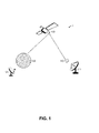
- FIG. 1 is an overview illustrating a satellite communications network 1 according to exemplary embodiments of the present invention.
- the satellite communications network includes a satellite 100, a hub 110, and a market area 120. and
- the hub 110 may include one or more audio, video and/or data providers (for example, one or more internet service providers, television/video/audio broadcasters, and/or telephone/voice/data services).
- the hub 110 includes one or more transmitting/receiving antennas 111.
- the market area 120 refers to a geographic area which may include a plurality of end users.
- the market area 120 may include one or more audio, video, and/or data providers.
- a plurality of transmitting/receiving antennas 121 are located with the market area 120 to communicate with the end users.
- the satellite 100 may be any object in orbit configured to transmit and receive radio waves to and from Earth.
- the satellite 100 may be in geostationary orbit, Molniya orbit, elliptical orbit, or low (polar or non-polar) Earth orbit.
- the satellite 100 may be, for example, a high throughput satellite that transmits and receives radio waves in the Ka band.
- the hub antenna 111 and the plurality of market antennas 121 are configured to transmit and receive radio waves to and from the satellite 100.
- the hub antenna 111 may be a 13 meter antenna and the market antennas 121 may be 60 or 90 centimeter antennas.
- the hub antenna 111 and the plurality of market antennas 121 may be configured to transmit radio waves to the satellite 100 in the 29,500 - 30,000 MHz frequency range and receive radio waves from the satellite 100 in the 19,700 - 20,200 MHz frequency range.
- Each of the hub antenna 111 and the plurality of market area antennas 121 can be connected to a controller (having a processor, a storage device such as memory, an input device, and/or a display) that controls the communication of signals over the respective hub antenna 111 or the market area antenna 121.
- the controller can be remotely located or co-located with the antenna 121 or 111.
- FIG. 2(a) is a schematic diagram illustrating prior art Ka band transponders 20a and 20b.
- Each of the prior art Ka band transponders 20a and 20b include a receiving antenna 21a, 21h, a filter 23a, 23b, a transponder/amplifier 24a, 24b, a filter 27a, 27b, and a transmitting antenna 28a, 27h. As illustrated in FIG.
- prior art Ka band satellites require two separate transponders: the transponder 20a configured to receive a signal U from the market area 120 through the market area receiving antenna 21a, perform signal processing and conditioning through filter 23a, transponder/amplifier 24a, and filter 27a, and transmit the signal U to the hub 110 through the hub transmitting antenna 29h; and the transponder 20b configured to receive a signal H from a hub 110 through the hub receiving antenna 21h, perform signal processing and conditioning through filter 23b, transponder/amplifier 24b, and filter 27b, and transmit the signal H to the market area 120 through the market area transmitting antenna 29a.
- FIG. 2(b) is a schematic diagram illustrating a transponder 200 according to an exemplary embodiment of the present invention.
- the transponder 200 includes a market area receiving antenna 210a configured to receive the signal U from the market area 120, a hub receiving antenna 210h configured to receive the signal H from the hub 110, an attenuator 216, a combiner 220, a filter 230, a transponder/amplifier 240, a coupler 260, filters 270a and 270h, and transmitting antennas 290a and 290h configured to transmit radio waves to the hub 110 and market area 120, respectively.
- the market area receiving antenna 210a and the hub receiving antenna 210h each include a low noise amplifier.
- the hub receiving antenna 210h is electrically connected to the attenuator 216.
- the attenuator 216 is configured to reduce the power of the radio waves received by the hub receiving antenna 210h, including the signal H and any natural noise generated by the hub receiving antenna 210h and its low noise amplifier.
- the power of the signal H transmitted by the hub transmitting antenna 121 is increased by an amount substantially equal to the amount of attenuation by the attenuator 216.
- the market area receiving antenna 210a and the attenuator 216 are electrically connected to the combiner 220.
- the combiner 220 is configured to receive a plurality of input signals and output a combined output signal.
- the combiner 220 may be a 2:1 combiner configured to receive signals from the receiving antennas 210a and 210h and output a combined output signal to the filter 230.
- the combiner 220 can combine any number of signals more than two.
- the combiner 220 combines the signal received by receiving antenna 210a from the market area 120 with the signal received by receiving antenna 210h from the hub 110 to provide a combined signal U+H.
- the filter 230 is configured to filter the combined signal 230.
- the transponder/amplifier 240 is configured to amplify and frequency convert the signal U+H.
- the transponder/amplifier 240 may include, for example, a traveling wave tube amplifier (TWTA), a down converter (for example, to convert the signal U+H from an uplink frequency to a downlink frequency), etc.
- TWTA traveling wave tube amplifier
- the transponder/amplifier 240 outputs the signal U+H to the coupler 260.
- the coupler 260 is configured to receive a combined input signal and output a plurality of output signals.
- the coupler 260 may be a 1:2 coupler which receives the combined input signal U+H from the transponder/amplifier 240 and couples the combined signal U+H (through the filters 270a and 270h, respectively) to both the market area transmitting antenna 290a and the hub transmitting antenna 290h.
- the coupler 260 may allocate up to 95 percent or more of the power density of the signal U+H to the market area transmitting antenna 290a while 5 percent or less of the power density of the signal U+H may be allocated to the hub transmitting antenna 290h.
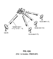
- FIG. 3 is an overview illustrating the satellite communications network 1 according to another exemplary embodiment of the present invention.
- the satellite communications network 1 includes a satellite 100, at least one hub 110 and a plurality of market areas 120.
- the satellite 100 includes a plurality of transponders, such as the transponder 200 illustrated in FIG. 2(b) .
- the satellite communications network 1 includes one hub 110 and four market areas 120.
- the hub 110 includes at least one hub transmitting/receiving antenna 111 and each market area 120 includes a plurality of market area transmitting/receiving antennas 121.
- the satellite 100 is configured to provide two-way communication between each of the market areas 120 and the hub 110 through the transponders 200.
- the market area 1 transmits an uplink signal U1 to the satellite 100 and the satellite 100 re-transmits the signal U1 as a downlink signal to the hub 110.
- the hub transmits an uplink signal H1 to the satellite 100 and the satellite 100 re-transmits the signal H1 to the market area 120.
- one of the plurality of market area transmitting/receiving antennas 121 of the market area 120 transmits an uplink signal U1 to the satellite 100.
- the uplink signal U1 is received by the market area receiving antenna 210a of the transponder 200 (illustrated in FIG. 2(a) ) of the satellite 100, combined by the combiner 220, filtered by the filter 230, amplified and frequency converted by the transponder/amplifier 240, divided by the coupler 260, filtered by the filter 270h, and transmitted as a downlink signal U1 by the hub transmitting antenna 270h to the hub 110 where it is received by the hub transmitting/receiving antenna 111.
- the hub transmitting/receiving antenna 111 of the hub 110 transmits an uplink signal H1 to the satellite 100.
- the uplink signal H1 is received by the hub receiving antenna 210h of the transponder 200, combined by the combiner 220, filtered by the filter 230, amplified and frequency converted by the transponder/amplifier 240, divided by the coupler 260, filtered by the filter 270a, and transmitted as a downlink signal H1 by the market area transmitting antenna 290a to the market area transmitting/receiving antennas 121 of the market area 120.
- the satellite 100 in addition to transmitting the downlink signal H1 to market area 1, the satellite 100 is also configured to transmit the signal U1 generated in the market area 1 back to the plurality of market antennas 121 of the market area 1.
- This enables a market antenna 121 located in the market area 1 to transmit a signal to all market antennas 121 within the market area 1 without requiring the signal U1 to be transmitted to, processed by, and re-transmitted from the hub 110.
- the plurality of market antennas 121 located within market area 1 is a television broadcast antenna
- the television broadcast may be transmitted to the plurality of market antennas 121 located within market area 1. Referring back to FIG.
- the transponder 200 enables a signal U to be transmitted back to the market area by combining the signal U from the market area 120 with the signal H from the hub 110 and simultaneously transmitting the combined signal U+H to both the market area 120 and the hub 110.
- the signals U and H are combined by the combiner 220 and distributed to both the market area 120 and the hub 110 by the coupler 260.
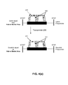
- FIG. 4(a) is a diagram illustrating the bandwidth usage of the transponder 200 according to exemplary embodiment of the present invention. Referring to FIG. 4(a) , the uplink signal from the hub 110 is transmitted by carrier wave 410 while the uplink signal from the market area 120 is transmitted by carrier wave 420.
- the carrier wave 410 from the hub 110 and the carrier wave 420 from the market area 120 are allocated on the same frequency segment (within the Ka band uplink frequencies) while the carrier wave 411 to the hub 110 and the carrier wave 421 to the market area 120 are allocated to the same frequency segment (within the Ka band downlink frequencies).
- the transponder 200 encompasses one or more carrier waves 410 from the hub 110 and one or more carrier waves 420 from the market area 120 in the same frequency slot and bandwidth.
- the satellite 100 may be used in conjunction with a hub 110 which is enabled with a Noise Reduction System (NRS).
- NRS Noise Reduction System
- the NRS of hub 110 may be, for example, the NRS described in U.S. Pat. No. 8,238,817 B1 to Avellan, et al. , which is incorporated herein by reference.
- a hub 110 which is enabled with the NRS described in Avellan transmits a signal H and receives an aggregate signal A from a plurality of remote stations (which are analogous to the market areas 120 of the present application).
- the aggregate signal A includes a signal H d , which is a replica of the original signal H from the hub 110 after it has suffered delays in time, shifts in frequency, changes in amplitude, and other distortions as it travels to and from the satellite.
- the NRS described in Avellan processes the aggregate signal A and removes the replica signal H d from the aggregate signal A.
- Removing the replica signal H d from the aggregate signal A enables the hub 110 to transmit and receive signals to and from a market area over the same frequency range without the uplink signal swamping the downlink signal.
- the satellite 100 of the present invention takes advantage of this ability and transmits a signal from a market area 120 to the hub 110 over the same frequency range as the hub 110 uses to transmit a signal to the market area 120.
- the satellite 100 provides satellite communication to a plurality of market areas 120.
- the demand from a market area 120 for satellite communications is such that a single transponder 200 is configured to provide satellite communications between that single market area 120 and the hub 110.
- a single transponder 200 may provide satellite communications for multiple market areas 120 (through multiple ground station receiving antennas 210 and multiple ground station transmitting antennas 290).
- the demand for satellite communications in each of the market areas 120 may change.
- FIG. 5 is a schematic diagram illustrating a payload architecture 500 of the satellite 100 according to an exemplary embodiment of the present invention.
- the payload architecture 500 includes at least one switchable transponder which may be re-configured from the ground while the satellite 100 is in orbit in order to respond to changing market conditions.
- the payload architecture 500 includes ground station receiving antennas 510, an attenuator 516, a combiner, 520, couplers 560, filters 570, and a plurality of ground station transmitting antennas 590.
- the ground station receiving antennas 510 may include a market area receiving antenna 510a configured to receive signals from the market area 1, a market area receiving antenna 510b configured to receive signals from the market area 2, a hub receiving antenna 510h configured to receive signals from a hub 110, and additional receiving antennas (not pictured) configured to receive signals from additional market areas 120.
- the ground station transmitting antennas 590 may include a market area transmitting antenna 590a configured to transmit signals to the market area 1, a market area transmitting antenna 590b configured to transmit signals to the market area 2, a hub transmitting antenna 590h configured to transmit signals to a hub 110, and additional transmitting antennas (not pictured) configured to transmit signals from additional market areas 120.
- the payload architecture 500 also includes low noise amplifiers (LNAs) 514, a down converter 524, and a traveling wave tube amplifier (TWTA) 526. These features may also be included in the transponder 200 illustrated in FIG. 2(b) .
- LNAs low noise amplifiers
- TWTA traveling wave tube amplifier
- the low noise amplifiers 514 are configured to amplify the signals received by the receiving antennas 510 and compensate for the loss in power which occurs from the ground transmission antenna to a receiving antenna 510.
- the attenuator 516 is configured to reduce the power of the radio waves received by the hub receiving antenna 510h, including the signal H and any natural noise generated by the hub receiving antenna 510h and the LNA 514. Similar to the attenuator 216 illustrated in FIG 2(b) , in order to compensate for the reduction in power caused by the attenuator 516, the power of the signal H transmitted by the hub transmitting antenna 121 is increased by an amount substantially equal to the amount of attenuation by the attenuator 516. By increasing the power of the signal H transmitted by the hub transmitting antenna 121, in combination with the attenuation of the signal H and the noise, the power level of the signal H remains constant while the amount of noise is reduced by the value of the attenuator.
- the combiner 520 is configured to combine signals received by the receiving antennas 510. Similar to the combiner 220 illustrated in FIG. 2(b) , the combiner 520 may combine a signal U received from a market area 120 with a signal H received from a hub 110.
- the down converter 524 is configured to convert the frequency of a signal from an uplink frequency (i.e., the frequency of a signal received by a receiving antenna 510) to a downlink frequency (i.e., the frequency at which the signal will be transmitted by a transmitting antenna 590). For example, the down converter 524 may convert an uplink signal in the 29,500-30,000 MHz range to a downlink signal in the 19,700-20,200 MHz range.
- the traveling wave tube amplifier 526 is configured to amplify radio waves.
- the coupler 560 is configured to receive a combined input signal and output a plurality of output signals. Similar to the coupler 260 illustrated in FIG. 2(b) , the coupler 560 may be a 1:2 coupler which receives the combined input signal U+H from the transponder/amplifier 240 and couples the combined signal U+H (through the filters 570) to both the hub transmitting antenna 290h and either a market area transmitting antenna 290 or the switching element 580.
- the payload architecture 500 also includes switching elements 530 and 580. As will be explained in detail with reference to FIGS. 6(a) through 6(e) , the switching elements 530 and 580 enable the satellite 100 to provide satellite communication to market area 1, market area 2, or both market area 1 and market area 2.
- FIGS. 6(a) through 6(e) are schematic diagrams illustrating the operation of the switching elements 530 and 580 (sometimes called “baseball switches") of the payload architecture 500 according to an exemplary embodiment of the present invention.
- the switching elements 530 and 580 enable the payload architecture 500 to connect the receiving antenna for market area 2 (through intervening elements) with the transmitting antenna from market area 2 ( FIG. 6(a) ), or to connect the receiving antenna for market area 1 (through intervening elements) with the transmitting antenna from market area 1 ( FIG. 6(d) ) and connect the receiving antenna for market area 2 (through intervening elements) with the transmitting antenna from market area 2 ( FIG. 6(e) ).
- the combiner 520 combines the signal U from the market area 120 with the signal H from the hub 110 and transmits a combined output signal U+H to both the hub 110 and the market area 120 (as illustrated in FIGS. 5 and 2(b) ).
- the switching element 530 includes a switch 631, a switch 632, and a combiner 633 and the switching element 580 includes a switch 681, a switch 682, and a divider 683.
- the combiner 633 which is similar to the combiner 220 described above with reference to Fig. 2(a) , is configured to combine two input signals and output a combined output signal. In the example illustrated in FIGS. 6(a) through 6(e) , the combiner 633 is a 2:1 combiner.
- the divider 683 is configured to divide one input signal and output two divided output signals. In the example illustrated in FIGS. 6(a) through 6(e) , the divider 683 is a 2:1 divider.
- the switch 632 of the switching element 530 is configured to connect the receiving antenna of the market area 2 (through intervening elements) to the switching element 580 and the switch 682 of the switching element 580 is configured to output a signal through the transmitting antenna for market area 2.
- the payload architecture 500 is configured to receive the signal U2 from market area 2 and transmit the corresponding response signal H2 from the hub 110 (along with the signal U2) to the market area 2.
- FIGS. 6(b) and 6(c) illustrate the operation of the switches 631, 632, 681, and 682.
- terminal A is in electrical communication with terminal D and terminal B is in electrical communication with terminal C.
- terminal A is in electrical communication with terminal B and terminal C is in electrical communication with terminal D.
- the switches 631 and 681 may operate in tandem. In other words, both the switch 631 and the switch 681 are configured either as illustrated in FIG. 6(b) or as illustrated in FIG. 6(c) .
- the switches 632 and 682 similarly may operate in tandem. Both switching elements 530 and 580 are re-configured in response to control signals received from ground, enabling the payload architecture 500 of the satellite 100 to be re-configured even after it is in orbit.
- the switches 631 and 632 of the switching element 530 are configured to connect the receiving antenna of the market area (through intervening elements) to the switching element 580 and the switches 682 and 681 of the switching element 580 are configured to output a signal through the transmitting antenna for market area 1.
- the payload architecture 500 is configured to receive the signal U1 from market area 1 and transmits the corresponding response signal H1 from the hub 110 (along with the signal U1) to the market area 1.
- the switch 631 of the switching element 530 is configured to connect the receiving antenna of the market area 1 (through intervening elements) to an input of the combiner 633 of the switching element 530 and the switch 632 of the switching element 530 is configured to connect the receiving antenna of the market area 2 (through intervening elements) to another input of the combiner 633.
- the combiner 633 outputs a combined signal U1+U2.
- the switches 631 and 632 are also configured to connect the output of the combiner 633 with the switching element 580.
- the switches 682 and 681 of the switching element 580 are configured to output the combined output signal of the payload architecture 500 to the divider 683 of the switching element 580.
- the divider 683 outputs two output signals, one the two output signals is connected through the switch 681 of the switching element 580 to the transmitting antenna for market area 1 and the other output signal is connected through the switch 682 of the switching element 580 to the transmitting antenna for market area two.
- the payload architecture 500 is configured to receive the signal U1 from market area 1 and transmits the corresponding response signal H1 from the hub 110 (along with the signals U1, U2, and H2) to the market area 1.
- the payload architecture 500 is also configured to receive the signal U2 from market area 2 and transmit the corresponding response signal H2 (along with the signals U2, U1 and H1) to the market area 2.
- the payload architecture 500 of the satellite 100 is configured to provide satellite communications to market area 1, market area 2, or both market areas 1 and 2.
- the switching elements 530 and 580 enable the payload architecture 500 to be re-configured in response to control signals from the ground such that the coverage areas of the payload architecture 500 may be adjusted in response to changes to changes in market conditions.
- the satellite 100 of FIG. 1 may include the loop back transponder 200 described with reference to FIGS. 2-3 , the frequency re-use described with reference to FIGS. 4 , and/or the switchable transponder described with reference to FIGS. 5-6 .
Landscapes
- Engineering & Computer Science (AREA)
- Physics & Mathematics (AREA)
- Astronomy & Astrophysics (AREA)
- Aviation & Aerospace Engineering (AREA)
- General Physics & Mathematics (AREA)
- Computer Networks & Wireless Communication (AREA)
- Signal Processing (AREA)
- Radio Relay Systems (AREA)
Applications Claiming Priority (1)
| Application Number | Priority Date | Filing Date | Title |
|---|---|---|---|
| US201261678337P | 2012-08-01 | 2012-08-01 |
Publications (2)
| Publication Number | Publication Date |
|---|---|
| EP2693659A2 true EP2693659A2 (fr) | 2014-02-05 |
| EP2693659A3 EP2693659A3 (fr) | 2016-09-21 |
Family
ID=48914132
Family Applications (1)
| Application Number | Title | Priority Date | Filing Date |
|---|---|---|---|
| EP13179004.0A Withdrawn EP2693659A3 (fr) | 2012-08-01 | 2013-08-01 | Satellite à haut rendement |
Country Status (2)
| Country | Link |
|---|---|
| US (2) | US9300390B2 (fr) |
| EP (1) | EP2693659A3 (fr) |
Families Citing this family (10)
| Publication number | Priority date | Publication date | Assignee | Title |
|---|---|---|---|---|
| AU2013341383B2 (en) | 2012-11-12 | 2017-08-24 | The Roger B. And Ann K. Mcnamee Trust U/T/A/D | Systems and methods for communicating a live event to users using the internet |
| US9872079B2 (en) * | 2013-03-15 | 2018-01-16 | The Roger B. And Ann K. Mcnamee Trust U/T/A/D | Systems and methods for distributing audio/video feed of a live event via satellite |
| US10664225B2 (en) | 2013-11-05 | 2020-05-26 | Livestage Inc. | Multi vantage point audio player |
| US10296281B2 (en) | 2013-11-05 | 2019-05-21 | LiveStage, Inc. | Handheld multi vantage point player |
| KR20160081122A (ko) * | 2014-12-30 | 2016-07-08 | 주식회사 쏠리드 | 다중입출력신호를 위한 분산 안테나 시스템 |
| US10103812B2 (en) | 2016-01-27 | 2018-10-16 | The Boeing Company | Satellite communication system |
| US11088757B2 (en) | 2017-03-16 | 2021-08-10 | Viasat, Inc. | High-throughput satellite with sparse fixed user beam coverage |
| US9973266B1 (en) | 2017-06-12 | 2018-05-15 | Ast & Science, Llc | System and method for high throughput fractionated satellites (HTFS) for direct connectivity to and from end user devices and terminals using flight formations of small or very small satellites |
| US10979133B2 (en) | 2017-06-12 | 2021-04-13 | Ast & Science, Llc | System and method for high throughput fractionated satellites (HTFS) for direct connectivity to and from end user devices and terminals using flight formations of small or very small satellites |
| EP4024727A1 (fr) | 2017-11-02 | 2022-07-06 | Intelsat US LLC | Procédés et systèmes destinés à augmenter l'efficacité de bande passante dans des communications par satellite |
Family Cites Families (4)
| Publication number | Priority date | Publication date | Assignee | Title |
|---|---|---|---|---|
| US6628922B1 (en) * | 2000-03-21 | 2003-09-30 | Harvey L. Berger | Communication system utilizing multiple satellites without intersatellite crosslinks |
| US20050032472A1 (en) * | 2003-08-08 | 2005-02-10 | Yimin Jiang | Method and apparatus of estimating non-linear amplifier response in an overlaid communication system |
| US8238817B1 (en) * | 2006-04-12 | 2012-08-07 | Emc Satcom Technologies, Llc | Noise reduction system and method thereof |
| US8111646B1 (en) * | 2009-07-30 | 2012-02-07 | Chang Donald C D | Communication system for dynamically combining power from a plurality of propagation channels in order to improve power levels of transmitted signals without affecting receiver and propagation segments |
-
2013
- 2013-08-01 EP EP13179004.0A patent/EP2693659A3/fr not_active Withdrawn
- 2013-08-01 US US13/956,900 patent/US9300390B2/en not_active Expired - Fee Related
-
2016
- 2016-03-29 US US15/084,126 patent/US20160254857A1/en not_active Abandoned
Non-Patent Citations (1)
| Title |
|---|
| None * |
Also Published As
| Publication number | Publication date |
|---|---|
| US20160254857A1 (en) | 2016-09-01 |
| EP2693659A3 (fr) | 2016-09-21 |
| US9300390B2 (en) | 2016-03-29 |
| US20140038515A1 (en) | 2014-02-06 |
Similar Documents
| Publication | Publication Date | Title |
|---|---|---|
| US9300390B2 (en) | High throughput satellite | |
| US8660482B2 (en) | Broadband satellite with dual frequency conversion and bandwidth aggregation | |
| US8750792B2 (en) | Transmitter for point-to-point radio system | |
| US20200028574A1 (en) | Paired-beam transponder satellite communication | |
| US6657978B1 (en) | Optimized integrated high capacity digital satellite trunking network | |
| US8547897B2 (en) | Coherent power combining for signals through multiple satellite communications channels | |
| EP2442460B1 (fr) | Zones de couverture flexibles pour signaux de liaison retour dans un système de communication satellite à faisceau étroit | |
| US9252869B2 (en) | Satellite telecommunications system for providing star traffic and mesh traffic | |
| US10382121B2 (en) | High capacity satellite communications system | |
| US9226269B2 (en) | Multi-waveform and wireless very high throughput radio system | |
| RU2439807C2 (ru) | Устройство широкополосного усиления | |
| US9973984B1 (en) | Satellite system with switched communication channels among earth stations | |
| CA2970531C (fr) | Systeme de modulateur numerique exterieur a utiliser avec une radio lineaire, et procede associe | |
| WO2019035113A1 (fr) | Système intégrant un réseau de satellites de communication avec un réseau cellulaire | |
| US20100081373A1 (en) | Satellite feed assembly with integrated filters and test couplers | |
| US10084543B2 (en) | Analog optical repeater and single optical line transmitting method for multi-band multiple-input multiple-output (MIMO) | |
| RU2210865C1 (ru) | Способ интерактивной абонентской связи и интерактивный абонентский терминал для его осуществления | |
| JP2006211171A (ja) | 中継増幅器 | |
| WO2006075466A1 (fr) | Relais amplificateur | |
| Davison et al. | Satellite Distribution | |
| JP2007208581A (ja) | 地上ディジタル放送再送信装置 |
Legal Events
| Date | Code | Title | Description |
|---|---|---|---|
| AK | Designated contracting states |
Kind code of ref document: A2 Designated state(s): AL AT BE BG CH CY CZ DE DK EE ES FI FR GB GR HR HU IE IS IT LI LT LU LV MC MK MT NL NO PL PT RO RS SE SI SK SM TR |
|
| AX | Request for extension of the european patent |
Extension state: BA ME |
|
| PUAI | Public reference made under article 153(3) epc to a published international application that has entered the european phase |
Free format text: ORIGINAL CODE: 0009012 |
|
| RIC1 | Information provided on ipc code assigned before grant |
Ipc: H04B 7/185 20060101AFI20160425BHEP |
|
| PUAL | Search report despatched |
Free format text: ORIGINAL CODE: 0009013 |
|
| AK | Designated contracting states |
Kind code of ref document: A3 Designated state(s): AL AT BE BG CH CY CZ DE DK EE ES FI FR GB GR HR HU IE IS IT LI LT LU LV MC MK MT NL NO PL PT RO RS SE SI SK SM TR |
|
| AX | Request for extension of the european patent |
Extension state: BA ME |
|
| RIC1 | Information provided on ipc code assigned before grant |
Ipc: H04B 7/185 20060101AFI20160815BHEP |
|
| 17P | Request for examination filed |
Effective date: 20170309 |
|
| RBV | Designated contracting states (corrected) |
Designated state(s): AL AT BE BG CH CY CZ DE DK EE ES FI FR GB GR HR HU IE IS IT LI LT LU LV MC MK MT NL NO PL PT RO RS SE SI SK SM TR |
|
| RAP1 | Party data changed (applicant data changed or rights of an application transferred) |
Owner name: TRIO CONNECT, LLC |
|
| 17Q | First examination report despatched |
Effective date: 20170412 |
|
| STAA | Information on the status of an ep patent application or granted ep patent |
Free format text: STATUS: THE APPLICATION IS DEEMED TO BE WITHDRAWN |
|
| 18D | Application deemed to be withdrawn |
Effective date: 20180417 |