EP2693660A2 - Synchronisationsverfahren und -system - Google Patents
Synchronisationsverfahren und -system Download PDFInfo
- Publication number
- EP2693660A2 EP2693660A2 EP13179058.6A EP13179058A EP2693660A2 EP 2693660 A2 EP2693660 A2 EP 2693660A2 EP 13179058 A EP13179058 A EP 13179058A EP 2693660 A2 EP2693660 A2 EP 2693660A2
- Authority
- EP
- European Patent Office
- Prior art keywords
- frequency
- time intervals
- intervals
- durations
- frequencies
- Prior art date
- Legal status (The legal status is an assumption and is not a legal conclusion. Google has not performed a legal analysis and makes no representation as to the accuracy of the status listed.)
- Withdrawn
Links
Images

Classifications
-
- H—ELECTRICITY
- H04—ELECTRIC COMMUNICATION TECHNIQUE
- H04B—TRANSMISSION
- H04B1/00—Details of transmission systems, not covered by a single one of groups H04B3/00 - H04B13/00; Details of transmission systems not characterised by the medium used for transmission
- H04B1/69—Spread spectrum techniques
- H04B1/713—Spread spectrum techniques using frequency hopping
- H04B1/7156—Arrangements for sequence synchronisation
-
- H—ELECTRICITY
- H04—ELECTRIC COMMUNICATION TECHNIQUE
- H04B—TRANSMISSION
- H04B7/00—Radio transmission systems, i.e. using radiation field
- H04B7/14—Relay systems
- H04B7/15—Active relay systems
- H04B7/185—Space-based or airborne stations; Stations for satellite systems
- H04B7/1851—Systems using a satellite or space-based relay
- H04B7/18513—Transmission in a satellite or space-based system
-
- H—ELECTRICITY
- H04—ELECTRIC COMMUNICATION TECHNIQUE
- H04W—WIRELESS COMMUNICATION NETWORKS
- H04W56/00—Synchronisation arrangements
- H04W56/0035—Synchronisation arrangements detecting errors in frequency or phase
Definitions
- the present invention relates to a method for frequency synchronization of a satellite terminal with a satellite or a terrestrial station. All of these elements belonging to the same system of satellite data transmission.
- low-cost satellite terminals generally include a local oscillator with poor performance
- the terminals generally have a frequency offset with the satellite or the earth station of several kHz, plus a possible shift caused by the Doppler effect.
- the time required for synchronization will therefore depend on the computing power available in the satellite terminal and the number of hypotheses to be made. For example, if the receiver needs to look for the synchronization signal in a range of 50kHz in steps of 1kHz, it is necessary for the satellite terminal to make 101 assumptions about the frequency offset. If each hypothesis requires a calculation of 10 seconds, the total synchronization time is about 17 minutes.
- the computing power necessary for a first synchronization is generally greater than the computing power necessary to follow this synchronization. The computing power used for the initial synchronization process is therefore underutilized for most of the time.
- the present invention therefore aims to remedy these problems by proposing a method and a frequency synchronization system limiting the computing power and the time required to achieve this frequency synchronization.
- a method for transmitting a frequency synchronization signal comprising a first step of determining at least two first transmission frequencies respectively associated with at least one first set of signals. at least two first time intervals separated temporally by a first duration. Said first time intervals are of identical duration. Said first durations are identical for identical first frequencies and said first durations are different for different first frequencies.
- the method also comprises a second step of transmitting a synchronization signal in the first time intervals and using respectively the first frequency associated with the time interval. Said synchronization signal transmitted in the different first intervals is identical.
- the proposed transmission method therefore allows the transmission of a synchronization signal having a higher spectral width compared to a normal method.
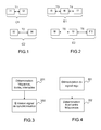
- the figure 1 illustrates the transmission of a synchronization signal in four time intervals. These time intervals are grouped into two first sets C1 and C2.
- the first set C1 comprises the time intervals I1 and I2 and the first set C2 comprises the time intervals I3 and I4.
- the signals transmitted in the time intervals of the first set C1 use a frequency band F1 and the signals transmitted in the time intervals of the first set C2 use a frequency band F2.
- the two time intervals of the first set C1 are separated from the duration T1 and the two time intervals of the first set C2 are separated from the duration T2 different from the duration T1.
- the two frequencies F1 and F2 used to emit a signal in the time intervals of the first sets C1 and C2 can be determined by comparison of the duration separating the two time intervals (I1 and I2 or I3 and I4) of the same pair of time intervals.
- the first step of the transmission method is adapted to determine at least two first frequencies whose spectral separation is greater than the spectral spreading bandwidth of the synchronization signal.
- This technical characteristic allows the emission of a synchronization signal having a double spectral width compared to a normal method.
- the first time intervals belong to a set of contiguous time intervals.
- the smallest common multiple of the first durations T1 is greater than a threshold.
- the smallest common multiple, also known as the PPCM, of two non-zero integers a and b is the smallest positive integer that is both multiple a and b .
- the threshold is equal to the number of first frequencies multiplied by the duration of the first time intervals.
- said first frequencies are respectively associated with at least three first time intervals separated temporally by two first durations.
- these two durations can be the duration between A and B, and the duration between B to C. It is also possible to define instead of the duration between A and B or the duration between B and C, the duration between A and C.
- This technical characteristic makes it possible to improve the reception performance of the synchronization signal, in particular by avoiding ambiguities and by limiting temporal estimation errors.
- the figure 2 illustrates an embodiment in which the transmission of a synchronization signal is carried out in six time intervals (I5 to I10). These time intervals are grouped into two first sets (E1 and E2).
- the first set E1 has three first time intervals (15 to 17).
- the first intervals I5 and I6 are separated by a duration T3 and the first intervals I6 and I7 are separated by a duration T4.
- the first set E2 has three first time intervals (I8 to I10).
- the first intervals I8 and I9 are separated by a duration T5 and the first intervals I9 and I10 are separated by a duration T6.
- the first intervals of the first set E1 are transmitted using the first frequency F1 and the first intervals of the first set E2 are transmitted using the first frequency F2.
- a reception method comprising a first demodulation step of the received signal, the demodulation is performed using a second frequency.
- the reception method also comprises a second step of determining the difference between at least one of the first frequencies and the second frequency by determining at least two second time intervals in which the energy of the demodulated signal is maximum.
- the proposed reception method thus makes it possible to determine the first frequency which has been used for the transmission of the synchronization signal in the pair of time intervals. This determination is made from the time separating the two time intervals of the couple.
- the reception method also uses the fact that the synchronization signals are identical and therefore it requires only one correlation with a synchronization signal. It is not necessary to make several correlations associated with different synchronization signals.
- the second step of the reception method is further adapted for determining a second duration separating the two second intervals and / or the comparison between the second duration and the said first periods.
- the second step of the reception method is furthermore suitable for determining at least three second time intervals in which the energy of said demodulated signal is maximum and / or for determining two second periods separating the two second intervals and / or the comparison between said second durations and said first durations.
- a frequency synchronization system comprising at least one satellite and / or at least one earth station capable of transmitting a frequency synchronization signal using the preceding transmission method.
- the system also comprises at least one satellite terminal capable of receiving a frequency synchronization signal by using the reception method.
- the emission process described on the figure 3 comprises a first step 201 for determining at least two frequencies resignation. Each of these frequencies is associated with a first duration which separates two time slots using this frequency. This first step also comprises selecting at least a pair of first time intervals separated from the first duration.
- the transmission method also comprises a second step 202 for transmitting a synchronization signal in each of the first two time intervals of the pair and using the first frequency associated with each pair. This signal is generally a pseudo-random sequence, modulated using a two-state modulation, known as BPSK.
- the transmission method therefore consists in transmitting a synchronization signal (also known as a beacon in the state of the art) in a pair of time intervals.
- a synchronization signal also known as a beacon in the state of the art
- the signals transmitted in pairs of different time intervals are at a different frequency.
- the transmission method therefore makes it possible to transmit on a higher frequency band than when transmitting synchronization signals using a single frequency.
- the receiver can determine the first frequency used for transmitting the signals of a pair of time intervals to from the time between these two time intervals.
- the figure 1 illustrates the transmission of a synchronization signal in four time intervals. These time intervals are grouped into two first sets C1 and C2.
- the first set C1 comprises the time intervals I1 and I2 and the first set C2 comprises the time intervals I3 and I4.
- the signals transmitted in the time intervals of the first set C1 use a frequency band F1 and the signals transmitted in the time intervals of the first set C2 use a frequency band F2.
- the two time intervals of the first set C1 are separated from the duration T1 and the two time intervals of the first set C2 are separated from the duration T2.
- the two frequencies F1 and F2 used to emit a signal in the time intervals of the first sets C1 and C2 can be determined by comparing the duration separating the two time intervals (I1 and I2 or I3 and I4) of the same pair of time intervals.
- first frequencies which are spectrally separated by a width greater than the width of the spreading band of the synchronization signal.
- the first time slots belong to a set of contiguous intervals.
- the first durations are chosen so that the smallest common multiple of these first durations is greater than a threshold equal to the number of first frequencies multiplied by the duration of the first time intervals.
- the figure 2 illustrates an embodiment in which the transmission of a synchronization signal is carried out in six time intervals (I5 to I10). These time intervals are grouped into two first sets (E1 and E2).
- the first set E1 has three first time intervals (15 to 17).
- the first intervals I5 and I6 are separated by a duration T3 and the first intervals I6 and I7 are separated by a duration T4.
- the first set E2 has three first time intervals (I8 to I10).
- the first intervals I8 and I9 are separated by a duration T5 and the first intervals I10 and I11 are separated by a duration T6.
- the first intervals of the first set E1 are transmitted using the first frequency F1 and the first intervals of the first set E2 are transmitted using the first frequency F2.
- the reception method described on the figure 4 comprises a first step 301 of demodulating the received signal. This demodulation is performed by considering that the frequency spreading band of the received signal is centered on a second frequency. Different demodulators are known in the state of the art.
- This reception method also comprises a second step 302 which makes it possible to determine the difference between at least a first frequency used for transmitting the synchronization signal and the second frequency.
- This second step is separated into two sub-stages as presented figure 5 .
- a first substep 401 which allows the determination of two second time intervals in which the energy of the demodulated signal is maximum.
- This step also comprises calculating a second duration separating these two second time intervals.
- a second sub-step 402 then compares this second duration with the first durations associated with the different first frequencies. This step makes it possible to determine the first frequency that was used to transmit the synchronization signals, in these two second time intervals.
- the receiver can then synchronize its local oscillators so that the second demodulation frequency depends on one of the first transmission frequencies of the synchronization signals.
- the method of the invention makes it possible, on transmission, to match each transmission frequency with a time separating the intervals on which the synchronization signal using this frequency is transmitted.
- a different duration is defined for each of the different frequencies.
- This mapping can for example be carried out via a correspondence table.
- the receiver detects the time intervals for which the signal power is maximum and determines the time between these time intervals in which the signal power is maximum. Then the receiver can do the opposite correspondence to that performed on transmission and thus find the transmission frequency of the synchronization signal.
- This inverse mapping can for example be carried out via a correspondence table.
- the figure 6 presents a system using the transmission method and the reception method.
- This system comprises a satellite 501, a land station 502 and a satellite terminal 503.
- the earth station generates the frequency synchronization signal using the transmission method and sends it to the satellite via the link 504. This signal is then repeated by the satellite and transmitted to the satellite terminal via the link 505. The satellite terminal is then able to carry out the reception method.
- the satellite is adapted to generate the synchronization signal by using the transmission method and sends it to the satellite terminal via the link 505.
- the satellite terminal is then able to carry out the reception method.
Landscapes
- Engineering & Computer Science (AREA)
- Computer Networks & Wireless Communication (AREA)
- Signal Processing (AREA)
- Physics & Mathematics (AREA)
- Astronomy & Astrophysics (AREA)
- Aviation & Aerospace Engineering (AREA)
- General Physics & Mathematics (AREA)
- Synchronisation In Digital Transmission Systems (AREA)
- Mobile Radio Communication Systems (AREA)
- Radio Relay Systems (AREA)
Applications Claiming Priority (1)
| Application Number | Priority Date | Filing Date | Title |
|---|---|---|---|
| FR1202182A FR2994367B1 (fr) | 2012-08-03 | 2012-08-03 | Procede et systeme de synchronisation |
Publications (2)
| Publication Number | Publication Date |
|---|---|
| EP2693660A2 true EP2693660A2 (de) | 2014-02-05 |
| EP2693660A3 EP2693660A3 (de) | 2017-11-15 |
Family
ID=47594808
Family Applications (1)
| Application Number | Title | Priority Date | Filing Date |
|---|---|---|---|
| EP13179058.6A Withdrawn EP2693660A3 (de) | 2012-08-03 | 2013-08-02 | Synchronisationsverfahren und -system |
Country Status (4)
| Country | Link |
|---|---|
| US (1) | US9325370B2 (de) |
| EP (1) | EP2693660A3 (de) |
| FR (1) | FR2994367B1 (de) |
| SG (1) | SG196766A1 (de) |
Cited By (1)
| Publication number | Priority date | Publication date | Assignee | Title |
|---|---|---|---|---|
| EP2720064B1 (de) * | 2012-10-12 | 2018-04-04 | Thales | Synchronisierungssystem einer Vorrichtung zur Satellitenausrichtung |
Families Citing this family (4)
| Publication number | Priority date | Publication date | Assignee | Title |
|---|---|---|---|---|
| JP6341890B2 (ja) * | 2015-07-08 | 2018-06-13 | 三菱電機株式会社 | 無線通信システム、中継機および端末無線機 |
| JP6552679B2 (ja) * | 2018-05-14 | 2019-07-31 | 三菱電機株式会社 | 無線通信システムおよび端末無線機 |
| US11101842B2 (en) * | 2019-04-18 | 2021-08-24 | Qualcomm Incorporated | Interference mitigation techniques in directional beamforming repeaters |
| CN116879845A (zh) * | 2023-06-25 | 2023-10-13 | 中国科学院空天信息创新研究院 | 一种频率同步方法、设备及系统 |
Family Cites Families (18)
| Publication number | Priority date | Publication date | Assignee | Title |
|---|---|---|---|---|
| US5638361A (en) | 1995-02-08 | 1997-06-10 | Stanford Telecommunications, Inc. | Frequency hopped return link with net entry channel for a satellite personal communications system |
| US6023477A (en) | 1996-12-18 | 2000-02-08 | Ericsson Inc. | System and method of time and frequency synchronization in a radiocommunication system |
| US5867478A (en) * | 1997-06-20 | 1999-02-02 | Motorola, Inc. | Synchronous coherent orthogonal frequency division multiplexing system, method, software and device |
| US6226336B1 (en) | 1998-02-20 | 2001-05-01 | Telefonaktiebolaget Lm Ericsson (Publ) | Method and apparatus for detecting a frequency synchronization signal |
| US6430211B1 (en) * | 1999-09-09 | 2002-08-06 | Pulse-Link, Inc. | Frequency hopping for baseband transmitters |
| US6606363B1 (en) | 1999-12-28 | 2003-08-12 | Telefonaktiebolaget Lm Ericsson (Publ) | Method and apparatus for estimating a frequency offset by combining pilot symbols and data symbols |
| US6956814B1 (en) * | 2000-02-29 | 2005-10-18 | Worldspace Corporation | Method and apparatus for mobile platform reception and synchronization in direct digital satellite broadcast system |
| US6937639B2 (en) * | 2001-04-16 | 2005-08-30 | Time Domain Corporation | System and method for positioning pulses in time using a code that provides spectral shaping |
| SG129230A1 (en) * | 2002-07-03 | 2007-02-26 | Oki Techno Ct Singapore Pte | Receiver and method for wlan burst type signals |
| US7224721B2 (en) * | 2002-10-11 | 2007-05-29 | The Mitre Corporation | System for direct acquisition of received signals |
| US7436876B2 (en) * | 2002-11-15 | 2008-10-14 | Time Domain Corporation | System and method for fast acquisition of ultra wideband signals |
| EP1977563B1 (de) * | 2006-01-11 | 2018-01-03 | QUALCOMM Incorporated | Codierung von bakensignalen zur identifikationsbereitstellung bei der peer-to-peer-kommunikation |
| EP1819067B1 (de) | 2006-02-08 | 2011-09-14 | Alcatel Lucent | Verfahren zur Synchronization von Übertragungen an Anwender in einem hybriden Funkübertragungsnetzwerk |
| US7889753B2 (en) * | 2006-11-16 | 2011-02-15 | Qualcomm Incorporated | Multiple access techniques for a wireless communication medium |
| US8369379B2 (en) * | 2008-05-19 | 2013-02-05 | Renesas Electronics Corporation | Packet synchronizing for communications over a wireless communication system |
| US8442095B2 (en) * | 2008-06-14 | 2013-05-14 | Qualcomm Incorporated | Multiple correlation processing in code space search |
| ATE519309T1 (de) * | 2008-11-03 | 2011-08-15 | Ericsson Telefon Ab L M | Schätzung einer frequenzumsetzung |
| JP5293480B2 (ja) * | 2009-07-27 | 2013-09-18 | 富士通株式会社 | 周波数制御装置、周波数制御方法及び基地局装置ならびに移動局装置 |
-
2012
- 2012-08-03 FR FR1202182A patent/FR2994367B1/fr active Active
-
2013
- 2013-07-31 US US13/956,239 patent/US9325370B2/en not_active Expired - Fee Related
- 2013-08-01 SG SG2013059241A patent/SG196766A1/en unknown
- 2013-08-02 EP EP13179058.6A patent/EP2693660A3/de not_active Withdrawn
Non-Patent Citations (1)
| Title |
|---|
| None |
Cited By (1)
| Publication number | Priority date | Publication date | Assignee | Title |
|---|---|---|---|---|
| EP2720064B1 (de) * | 2012-10-12 | 2018-04-04 | Thales | Synchronisierungssystem einer Vorrichtung zur Satellitenausrichtung |
Also Published As
| Publication number | Publication date |
|---|---|
| EP2693660A3 (de) | 2017-11-15 |
| FR2994367A1 (fr) | 2014-02-07 |
| US9325370B2 (en) | 2016-04-26 |
| SG196766A1 (en) | 2014-02-13 |
| US20140036962A1 (en) | 2014-02-06 |
| FR2994367B1 (fr) | 2016-07-15 |
Similar Documents
| Publication | Publication Date | Title |
|---|---|---|
| EP2387189B1 (de) | Verfahren zur Demodulation von Signalen eines Mehrfachzugriffsystems, die untereinander eine Kollision verursachen können, und Instrumente zu deren Umsetzung | |
| WO1991018458A1 (en) | A high frequency multichannel diversity differential phase shift (dpsk) communications system | |
| US7471743B2 (en) | Systems and methods for high-efficiency transmission of information through narrowband channels | |
| EP2693660A2 (de) | Synchronisationsverfahren und -system | |
| US10339623B2 (en) | Phase rotation watermarking for phase modulation | |
| FR2734107A1 (fr) | Procede et dispositif pour la recuperation d'horloge de synchronisation par symboles a partir d'un signal possedant de grandes possibilites en frequence | |
| EP3931991B1 (de) | Verfahren und vorrichtung zur modulierung mit zadoff-chu-sequenzen | |
| US10785086B1 (en) | Detection of phase rotation modulation | |
| FR2976429A1 (fr) | Systeme de transmission sans fil | |
| CN106656304B (zh) | 一种基于相关性的星载ais信号接收处理方法及装置 | |
| US7864887B2 (en) | Noncoherent symbol clock recovery subsystem | |
| WO2017129799A1 (fr) | Récepteur de communication radio annulant la polarisation croisée d'un signal reçu | |
| FR3109851A1 (fr) | Méthode de réception d’un signal modulé en amplitude et récepteur associé | |
| US7359452B2 (en) | Systems and methods for designing a high-precision narrowband digital filter for use in a communications system with high spectral efficiency | |
| US9419834B2 (en) | MPSK demodulation apparatus and method | |
| RU2782450C1 (ru) | Способ демодуляции сигналов с относительной фазовой манипуляцией | |
| US7269230B2 (en) | Systems and methods for designing a high-precision narrowband digital filter for use in a communications system with high spectral efficiency | |
| JP4180967B2 (ja) | 信号復調装置 | |
| Jerbi | Non-coherent detection of continuous phase modulation for low earth orbit satellite IoT communications affected by Doppler shift | |
| WO2007133651A2 (en) | High-efficiency transmission of information through narrowband channels based on ultra spectral modulation | |
| WO2006069872A1 (fr) | Procédé et dispositif d'émission d'un signal multiporteuse avec décalage temporel d'un sous-ensemble d'éléments de symbole, signal, procédé et dispositif de réception correspondants | |
| FR2998122A1 (fr) | Recepteur ofdm | |
| FR2979775A1 (fr) | Procede de synchronisation et de reception d'un recepteur radio, et recepteur adapte pour mettre en oeuvre un tel procede |
Legal Events
| Date | Code | Title | Description |
|---|---|---|---|
| AK | Designated contracting states |
Kind code of ref document: A2 Designated state(s): AL AT BE BG CH CY CZ DE DK EE ES FI FR GB GR HR HU IE IS IT LI LT LU LV MC MK MT NL NO PL PT RO RS SE SI SK SM TR |
|
| AX | Request for extension of the european patent |
Extension state: BA ME |
|
| PUAI | Public reference made under article 153(3) epc to a published international application that has entered the european phase |
Free format text: ORIGINAL CODE: 0009012 |
|
| PUAL | Search report despatched |
Free format text: ORIGINAL CODE: 0009013 |
|
| AK | Designated contracting states |
Kind code of ref document: A3 Designated state(s): AL AT BE BG CH CY CZ DE DK EE ES FI FR GB GR HR HU IE IS IT LI LT LU LV MC MK MT NL NO PL PT RO RS SE SI SK SM TR |
|
| AX | Request for extension of the european patent |
Extension state: BA ME |
|
| RIC1 | Information provided on ipc code assigned before grant |
Ipc: H04W 56/00 20090101ALI20171010BHEP Ipc: H04B 7/185 20060101AFI20171010BHEP |
|
| STAA | Information on the status of an ep patent application or granted ep patent |
Free format text: STATUS: REQUEST FOR EXAMINATION WAS MADE |
|
| 17P | Request for examination filed |
Effective date: 20180514 |
|
| RBV | Designated contracting states (corrected) |
Designated state(s): AL AT BE BG CH CY CZ DE DK EE ES FI FR GB GR HR HU IE IS IT LI LT LU LV MC MK MT NL NO PL PT RO RS SE SI SK SM TR |
|
| STAA | Information on the status of an ep patent application or granted ep patent |
Free format text: STATUS: EXAMINATION IS IN PROGRESS |
|
| 17Q | First examination report despatched |
Effective date: 20190612 |
|
| STAA | Information on the status of an ep patent application or granted ep patent |
Free format text: STATUS: THE APPLICATION IS DEEMED TO BE WITHDRAWN |
|
| 18D | Application deemed to be withdrawn |
Effective date: 20210128 |