EP2695533A2 - Machine de fabrication de produits en forme de tiges de l'industrie de traitement du tabac - Google Patents
Machine de fabrication de produits en forme de tiges de l'industrie de traitement du tabac Download PDFInfo
- Publication number
- EP2695533A2 EP2695533A2 EP13179508.0A EP13179508A EP2695533A2 EP 2695533 A2 EP2695533 A2 EP 2695533A2 EP 13179508 A EP13179508 A EP 13179508A EP 2695533 A2 EP2695533 A2 EP 2695533A2
- Authority
- EP
- European Patent Office
- Prior art keywords
- format
- reference surface
- vii
- functional assembly
- machine according
- Prior art date
- Legal status (The legal status is an assumption and is not a legal conclusion. Google has not performed a legal analysis and makes no representation as to the accuracy of the status listed.)
- Granted
Links
Images





Classifications
-
- A—HUMAN NECESSITIES
- A24—TOBACCO; CIGARS; CIGARETTES; SIMULATED SMOKING DEVICES; SMOKERS' REQUISITES
- A24C—MACHINES FOR MAKING CIGARS OR CIGARETTES
- A24C5/00—Making cigarettes; Making tipping materials for, or attaching filters or mouthpieces to, cigars or cigarettes
- A24C5/14—Machines of the continuous-rod type
- A24C5/18—Forming the rod
- A24C5/1807—Forming the rod with compressing means, e.g. garniture
-
- A—HUMAN NECESSITIES
- A24—TOBACCO; CIGARS; CIGARETTES; SIMULATED SMOKING DEVICES; SMOKERS' REQUISITES
- A24C—MACHINES FOR MAKING CIGARS OR CIGARETTES
- A24C5/00—Making cigarettes; Making tipping materials for, or attaching filters or mouthpieces to, cigars or cigarettes
- A24C5/14—Machines of the continuous-rod type
- A24C5/24—Pasting the seam
-
- A—HUMAN NECESSITIES
- A24—TOBACCO; CIGARS; CIGARETTES; SIMULATED SMOKING DEVICES; SMOKERS' REQUISITES
- A24C—MACHINES FOR MAKING CIGARS OR CIGARETTES
- A24C5/00—Making cigarettes; Making tipping materials for, or attaching filters or mouthpieces to, cigars or cigarettes
- A24C5/14—Machines of the continuous-rod type
- A24C5/18—Forming the rod
- A24C5/1857—Belt construction or driving means
-
- A—HUMAN NECESSITIES
- A24—TOBACCO; CIGARS; CIGARETTES; SIMULATED SMOKING DEVICES; SMOKERS' REQUISITES
- A24C—MACHINES FOR MAKING CIGARS OR CIGARETTES
- A24C5/00—Making cigarettes; Making tipping materials for, or attaching filters or mouthpieces to, cigars or cigarettes
- A24C5/14—Machines of the continuous-rod type
- A24C5/26—Drying the seam
-
- A—HUMAN NECESSITIES
- A24—TOBACCO; CIGARS; CIGARETTES; SIMULATED SMOKING DEVICES; SMOKERS' REQUISITES
- A24C—MACHINES FOR MAKING CIGARS OR CIGARETTES
- A24C5/00—Making cigarettes; Making tipping materials for, or attaching filters or mouthpieces to, cigars or cigarettes
- A24C5/14—Machines of the continuous-rod type
- A24C5/31—Machines of the continuous-rod type with special arrangements coming into operation during starting, slowing-down or breakdown of the machine, e.g. for diverting or breaking the continuous rod
Definitions
- the invention relates to a machine for the production of rod-shaped products of the tobacco-processing industry having the features of the preamble of claim 1.
- Such machines include, among other important functional assemblies, a format assembly having a trim assembly in which a wrapping strip is wrapped around a strand of a product such as a wrapping strip. Tobacco or filter material, beaten around, glued by means of a glue nozzle and glued in an adhesive chamber. After the adhesive chamber, a seam heating is provided, which is directed to the glue seam and hardens the glue by heating.
- the format set comprises a format base with at least one channel which, starting from a flat base, has a decreasing radius in the longitudinal direction, that is to say it recesses in the longitudinal direction of the format base.
- a driven format tape is guided, on which an endless strand of the product rests with a wrapping strip. Due to the shape of the channel in the direction of the format strip of the wrapping strip is struck during the transport movement on the sides of the loose strand lying up.
- the garniture includes one or more format tops which are shaped to complement the trough at the top in the direction of travel of the format tape with a decreasing radius as far as a closed channel, so that the wrapper strip during the further transport movement after the lateral beating on the top is further beaten around the strand.
- a glue line is applied to one of the edges of the wrapping strip by means of a glue nozzle, by means of which the edges of the wrapping strip are subsequently glued together in an adhesive chamber to fix the shape of the strand. After bonding the edges, they are heated to harden the glue via a seam heater.
- the format tape itself is deflected at the entrance and exit of the format garnish on format band deflection rollers, the wrapping strip and the strand are placed at the entrance of the Forming garniture after the deflection of the format strip successively and removed the form-fixed strand at the output of the Formiturnitur before deflecting the format strip of the format tape becomes.
- a scraper is provided, which is directed at an angle and with a small gap on the format tape and strips on the format tape adhering tobacco residues or other particles.
- a second scraper is provided, which is directed to the format band deflection roller at the exit of the format band set and serves to remove existing residues from the format band deflection roller.
- a Strangabditer is provided at the output of the garniture, with which the strand as needed from the proposed transport path, for example, in discovered errors, led out and the transport of the strand can be interrupted in the machine.
- the garniture must be replaced in parts or in total (format change) because the geometry of the form-fixed strand and the products subsequently separated by the geometry the gutter and the chamber is predetermined.
- the above function modules After changing the parts of the garniture, the above function modules must be realigned to the new parts of the garniture and / or the rest of the format tape strand other format, which is very complex and time-consuming due to the tight tolerances.
- the invention has the object to provide a machine of the generic type, which should have a simpler structural design and in the format change easier and faster in particular can be performed.
- the orientation and / or the arrangement of the reference surface can be changed.
- the arrangement and orientation of the respective reference surface to the strand or the part of the pattern set is chosen so that the functional assembly is positioned with the crucial parts equal to the predetermined orientation and arrangement.
- the coding of the arrangement of the functional assembly to the part of the garniture and / or to the strand is thus realized by the arrangement and the orientation of the reference surface on the part of the garniture, so that the functional assembly automatically by the arrangement on the reference surface automatically formatindividuell in their predetermined Orientation and arrangement is positioned to the strand and / or to the format part.
- the functional assembly no longer needs to be adjusted after placement on the reference surface because the information about the predetermined placement and alignment of the functional assembly with the part of the trim assembly or strand is provided by the provision of the reference surface in the portion of the trim assembly itself.
- the format change itself considerably simplified by the proposed solution due to the discontinued adjustment of the function module and in particular be done faster.
- the reference surface in the arrangement and orientation can also be chosen so that the function module can only be mounted and / or the entire machine can only be put into operation when the function module is applied to the reference surface. By changing the reference surface in its orientation or arrangement, the positioning of the functional assembly prior to abutment with the reference surface may be preset to match product properties, with the coding of the predetermined position of the functional assembly still being included in the format part itself.
- the trim set can be set individually to the particular shape of the products to be produced, whereby the functional assemblies themselves need not be deliberately changed or adjusted. Rather, identical functional assemblies can be used to make products of different formats, which can significantly reduce the cost of stocking the functional assemblies as well as the cost and time to retool the machine. Thus, it is also possible, for example, to replace a functional module with a functional module of another machine, which is not operated at this time for any reason.
- the functional module can be moved by means of an adjusting device from the system on the reference surface into a format change position and vice versa.
- the Functional assembly must therefore not completely dismantled to the format change, but instead be moved only in the format change position, from which it can be moved by means of the adjustment by the system on the reference surface of the new format part immediately in the new intended position.
- the adjusting device may comprise a stationary pivot bearing, wherein the movement of the functional assembly from the system to the reference surface in the format change position in this case is realized particularly handling friendly by a pivoting movement about the fixed pivot bearing.
- the functional assembly does not need to be disassembled, but only pivoted, which can be done by easy-to-carry out handling operations.
- the function module is spring-loaded in the direction of the system on the reference surface.
- the function module thereby pivots automatically in the predetermined position, depending on the spring forces acting If necessary, additionally a fastening in the desired position can be provided. Furthermore, it can be ensured by the spring load of the function module that the function module always rests against the reference surface and adjusted against the acting spring force or must be pivoted to the format change position.
- At least one first functional assembly has a reference surface which is aligned and arranged such that a second functional assembly by abutment with the reference surface of the first functional assembly in a predetermined orientation and arrangement to the Form Garnitur and / or is positioned in the strand.
- the second reference surface practically creates a chain reference system which, starting with the first reference surface, also makes it possible to arrange further functional assemblies in a predetermined alignment with the strand and / or the format parts.
- the orientation and / or the arrangement of the reference surface can be structurally particularly easily changed by an adjusting device, wherein the adjusting device can be formed by a control part with a linear adjusting movement particularly preferred.
- the alignment and / or arrangement of the function assembly can be adjusted, the adjustment can also be made with already arranged on the format set function module with a corresponding accessibility of the adjusting device, so that the set Alignment and / or arrangement of the function module can be checked immediately to the style set and readjusted if necessary.
- the construction can be considerably simplified as a whole, since the functional assembly and its holder for changing the orientation and / or arrangement need not be changed, and in particular the functional assembly need not have any adjustment.
- the reference surface has an immediate positional relationship with the strand guided in the format and the wrapping strip to be glued, so that, for example, the arrangement and / or orientation of the glue nozzle by the proposed adjustment of the reference surface on the garniture with a very small tolerance chain or can be adjusted with a very high accuracy to the strand and the wrapping strip.
- the adjusting device is formed by a setting part with a linear adjusting movement, since the orientation and / or arrangement is thereby proportional to the adjusting movement and thereby characterized. manually set particularly easy.
- an actuator can e.g. a grub screw or an eccentric screw.
- the actuating part can be fixed by means of a locking device.
- the locking device the control part can be determined by changing the position of the reference surface by the locking device, so that the position of the reference surface then, for example during operation of the machine can not change unintentionally.
- the adjusting device comprises a pivoting part which is mounted in a stationary pivot bearing, and the pivoting part abuts with a stop on the actuating part, and the movement of the actuating part via the pivoting part to the functional assembly is transferable.
- the pivoting part By the pivoting part, the adjustment movement of the reference surface can be transferred to a more distant contact surface of the function module.
- the adjustment movement can be sub-translated or translated.
- the function module can also be forced against the reference surface by utilizing the tensile or compressive forces exerted by the format band. This is particularly useful in the function module I of the format tape outlet, since the format tape exerts a moment on the functional assembly I by the guide down at an arrangement of the pivot bearing on the side facing the format set side of the format band deflection, which the functional assembly I with the pivoting part against the Bottom of the format set urges.
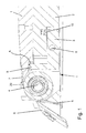
- Fig. 1 is a section of a machine according to the invention can be seen with a format base 1 of a trim set on a machine bed 2, on which a format strip 20 is guided.
- the format tape 20 is driven and transported an unillustrated endless strand of a product of the tobacco processing industry, such as cigarette butts or filters, through the format set, wherein it is on a in the Fig. 2 to be recognized channel 23 of the format reason 1 rests.
- the strand lifts from the format base runner 7 from the format belt 20 and is then cut in a downstream cutter into products of a predetermined length.
- the format strip 20 is deflected at a first Form michsbandumlenkrolle 4 and returned via a drive means, not shown, to the inlet in the format garnish, where it again before the enema via a in the Fig. 9 to be recognized second format band deflection roller 34 is deflected.
- first Form michsbandumlenkrolle 4 two scrapers 5 and 6 are provided, which are directed to clean the format strip 20 and for cleaning the Form réellesbandumlenkrolle 4 with the tip in each case at an angle and with a small gap on the respective modules.
- the format band deflection roller 4 forms with the scrapers 5 and 6 in a predetermined arrangement and orientation to the format base 1 positioned functional assembly I, which pivotally with a pivoting part 3 on a Swivel bearing 9 is stored.
- a reference surface A is provided, which is positioned in a defined orientation and arrangement to the Formatcampusauslauf 7 and the format base 1 itself.
- the pivoting part 3 is provided with a stop 8 and spring-loaded by a spring 10 in a direction in which the functional assembly I rests with the stop 8 on the reference surface A.
- the stopper 8 has a defined positional relationship to the format band deflection roller 4, so that the format band deflection roller 4 is automatically arranged in a contact arrangement of the stop 8 on the reference surface A in a predetermined by the position of the reference surface A arrangement and orientation to the format base 1.
- the same principle of alignment also applies to the second format band deflection roller 34 at the entrance to the format set, wherein the first Form istsbandumlenkrolle 4 at the output and the second Formbandumlenkrolle 34 at the entrance due to a fixed positional relationship of the reference surfaces A and H at the same time also a predetermined orientation and Arrangement to each other, so that the format strip 20 is preferably inserted according to tangential preferably in the format set and led out again.
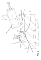
- the format set can be seen in cross-section with format base 1 and format top sections 11 and 12.
- the channel 23 in the format base 1 is continued by lateral abutment surfaces on the upper format parts 11 and 12 up to an almost closed channel, so that the wrapping strip is almost completely wrapped around the strand except for the upstanding on the lateral abutment surface 24 of the format top 11 edge ,
- a function assembly II is provided with a glue nozzle 13, which is directed with an outlet opening 15 on the edge of the voltage applied to the contact surface 24 wrapping strip.
- the Functional assembly II is also mounted with a pivoting part 3 about a pivot bearing 9, which in the first embodiment in the Fig. 2 abuts with a stop 8 on a reference surface B.
- the reference surface B is in this case the front side of a grub screw 32, which can be adjusted by turning in height.
- the reference surface C is formed by the edge side of an eccentric of an eccentric screw 14 screwed into the format upper part 12.
- the glue nozzle 13 comes into contact with the reference surface C with a shoulder of a telescopic extension device which limits the extension movement of the glue nozzle 13 and defines the position of the outlet opening 15 relative to the upstanding edge of the wrapping strip.
- the position of the outlet opening 15 is fixed to the edge of the wrapping strip by the reference surface C, the orientation and arrangement can be changed by turning the eccentric screw 14.
- the eccentric screw 14 is passed through a bore of the format upper part 12 and screwed into a corresponding thread of the Formatgroundes 1.
- the eccentric screw 14 is part of the Formatgroundes 1 and includes by their orientation the information about the orientation of the glue nozzle to the format base 1 and the entire format set.
- the position of the functional assembly II by turning the grub screw 32 or the eccentric screw 14 and a change of the reference surfaces B and C preset or even in the arranged on the format garnish position of the functional assembly II can be changed.
- the information about the relative position of the functional assembly II to the format reason 1 in the format reason 1 itself is included.
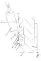
- a seam heater 17 formed by a seam heater 17, shown.
- the seam heater 17 is mounted on a holder 25, which is held on a pivot member 3 via a linear guide 27 with, for example, a ball cage or a ball guide.
- the pivoting part 3 is pivotably mounted about a pivot bearing 9 by means of an adjusting device 18 and can thereby be pivoted together with the holder 25 out of contact with a reference surface D of a grub screw 32 in a format change position and vice versa.
- the pivoting movement of the pivoting part 3 and the holder 25 is limited by conditioning a bolt 26 with a stop 8 on the reference surface D against the format base 1, whereby the position of the seam heater 17 is defined to the channel 23 and guided therein, not shown strand.
- the seam heater 17 is coupled via the holder 25 to the pivot mechanism such that the seam heater 17 is always arranged perpendicular to the channel 23.
- the pivoting mechanism is designed such that the pivoting part 3 with the leg, on which the holder 25 is held, always pivoted exactly in the horizontal orientation.
- the position of the seam heater 17 to the strand is defined by the reference surface D and the orientation or the position of the stopper 8 to the seam heater 17.
- FIG. 5 is another embodiment with a functional assembly IV, formed by a closure device of an adhesive chamber to recognize.
- the closure device likewise has a pivoting part 3, which is pivotably mounted in a pivot bearing 9 and on which a format upper part 19 closing the adhesive chamber in the circumferential direction is held.
- the format upper part 19 has two pins 22 with positioning discs 21 which define the relative position of the format upper part 19 relative to the pivoting part 3.
- the positioning discs 21 have reference surfaces E, which determine the position of the format upper part 19 relative to the pivoting part 3.
- the stop 8 is in this case the corresponding mating surface of the pivoting part 3, to which the positioning discs 21 come to rest with the reference surface E.
- the reference surfaces E are the side surfaces of the positioning discs 21, which can be changed by using other positioning discs 21.
- positioning discs 21 with an oversized opening may also be used so that they can be displaced laterally on the pin 22 to change the orientation and arrangement of the side surfaces.
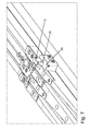
- FIG. 6 and Fig. 7 an alternative embodiment of the machine can be seen, in which an adapter piece 30 with two grub screws 29 and 28 is attached to the format set.
- the adapter piece 30 is attached laterally to the format base 1 of the format set, so that the format tops 11 and 12 of the format set must not be changed.
- the grub screws 28 and 29 are aligned and arranged on the adapter piece 30, that the first grub screw 28 vertically and the second grub screw 29 are aligned horizontally and perpendicular to the run in the Formgarnitur strand.
- the end faces of the grub screws 28 and 29 form the reference surfaces B and C, where the functional assembly II with the glue nozzle 13 is applied.
- a stop is provided on the functional assembly II, with which the functional assembly II rests against the reference surface C of the horizontally oriented second grub screw 29. Further, a pivotally mounted in a stationary pivot bearing 9 pivoting part 3 is provided on the machine, which rests with a lever arm on the functional assembly II and rests with the other lever arm with a stop 8 on the reference surface B of the first set screw 28.
- the adapter piece 30 is expedient insofar as a processing of the format upper parts 11 and 12 would be very costly for the formation of reference surfaces and also on each of the replaced format parts 11 or 12 corresponding reference surfaces would have to be provided.
- the format parts 11 or 12 can be exchanged, and the reference surfaces B and C are provided by attaching the same adapter piece 30 on the format set. It is particularly important that the adapter piece 30 is not part of the functional assembly II with the glue nozzle 13, so that different functional assemblies II or functional assemblies II can be positioned with different glue nozzles 13 using a single adapter piece 30 on the pattern.
- the second grub screw 29 is rotated, whereby the functional assembly II is moved horizontally linear.
- the orientation of the glue nozzle 13 in the vertical direction can be adjusted by the first set screw 28 is rotated and thereby pivots the pivot member 3 and the function assembly II is raised.
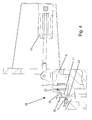
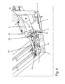
- a functional assembly V is arranged according to the invention with a Abrangabtrainr 33 at the outlet of a format garnish.
- a swivel mounted in a stationary pivot bearing 9 pivoting part 3 is provided, which rests with a stop 8 on a front-side reference surface F of a screwed into the format set grub screw 32.
- the pivoting part 3 is also applied to the functional assembly V with the Abrangabtrainr 33, so that the functional assembly V can be raised or lowered vertically by rotating the grub screw 32 and thereby caused pivoting of the pivot member 3 about the pivot bearing 9.
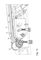
- the functional assemblies VI and VII of the paper deflection roller 35 of the paper inlet and the second format belt deflection roller 34 can be seen on the format inlet.
- the orientation of the functional assembly VI of the paper inlet is determined by the reference surface G, which is formed by the end face of a screwed into the base 1 grub screw 32.
- a stop 8 of a pivoting part 3 At the reference surface G of the grub screw 32 is a stop 8 of a pivoting part 3, which in turn is pivotally mounted in an unrecognizable machine-fixed pivot bearing and rests with a lever arm on the functional assembly VI of the paper inlet.
- a locking screw 40 is first released on the functional assembly VI and then the function assembly VI adjusted by turning the grub screw 32, in which pivots the pivot member 3 via the voltage applied to the stop 8 with the reference surface G grub screw 32 and thereby raises or lowers the function module VI.
- the reference surface G is provided here on the front side of the grub screw 32, which can be changed or adjusted in position by turning the grub screw 32. This makes it possible to adjust the orientation of the Paper Feed Function Assembly VI directly on the machine, directly inspecting the nominal dimensions of the Function Assembly VI to the format set.
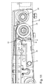
- the function module VII format infeed with the format band deflection roller 34 is also a in the Fig. 11 set to be detected pivot part 3b, which is pivotally mounted in a likewise fixed machine pivot bearing 9 and rests with a stop 8 on a reference surface H.
- the reference surface H is also formed by the end face of a grub screw 32, and can be changed and adjusted in position by turning the grub screw 32.
- the functional assemblies VI and VII can be seen in other views, wherein the pivoting parts 3 are designated here for the sake of better distinction with 3a and 3b.
- the pivoting part 3 of the functional assembly VII of the format tape inlet is 3b and the pivoting part 3 of the functional assembly VI of the paper inlet is denoted by 3a.
- the functional modules I, II, III, IV, V, VI and VII must therefore no longer be set separately after a replacement of the format reason 1 or the format tops 11, 12, 19 in a format change, but only with the stops 8 at the reference surfaces A. , B, C, D, E, F, G and H are brought to bear, if they are already in the desired position. It is particularly important that the functional assemblies I, II, III, IV, V, VI and VII are each rotatably connected to the pivoting parts 3, so that the pivotal movement of the pivoting parts 3 is transmitted to this.
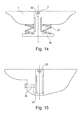
- FIGS. 14 and 15 is an example of a backup of the grub screw 32 from the in the Fig. 4 shown embodiment shown in more detail.
- the grub screw 32 in the Fig. 14 is formed T-shaped with a provided at the end of the grub screw 32 plate 38 and screwed into a threaded hole of the Formatgroundes 1, so that the plate 38 of the grub screw 32 covers a lower wall side of the Formatgroundes 1.
- a spring 37 is provided, which is supported between the plate 38 and the lower wall side of the Formatgroundes 1 and thereby biases the grub screw 32.
- the grub screw 32 is characterized by an increased frictional engagement with the thread in the threaded hole and can not rotate independently from the once set position. As a result, the orientation of the reference surface D on the front side of the grub screw 32 is not or only difficult to move out of the target position. The grub screw 32 is practically secured in the set nominal position.
- the grub screw 32 is secured by a laterally fitting clamping piece 39, which is pressed by a screw 36 to the shank of the grub screw 32 and secures the grub screw 32 against unintentional rotation.
- the clamping piece 39 and the spring 37 form in both embodiments locking devices, which prevent the grub screw 32 unintentionally dissolves or twisted and thereby changes the position of the reference surface D.
- the grub screw 32 forms in the described embodiments, the adjusting device or the adjusting part with the linear adjusting movement, by which the orientation of the reference surface can be changed.
- the change in the orientation or the position takes place in that the grub screw 32 is rotated, whereby it is linearly displaced along its longitudinal axis due to the thread pitch.
- the distance between the reference surface D and the format base 1 and the distance between the functional module III reaching the reference surface D can be changed.
- the invention has been described in particular with emphasis on the variable or adjustable reference surface, wherein the individual coupling of the individual functional modules I to VII are to be considered individually for themselves as independent inventions.
- the functional modules I to VII directly, as described with reference to the functional assemblies II and III, or indirectly by investing a rotatably connected to the respective function module pivoting part 3, as described by the functional assemblies I, V, VI, VII, are adjusted in the position to the format set.
- the trim set Due to the arrangement and adjustment of the reference surfaces A, B, C, D, E, F, G and H, the trim set is practically customized for the different products to be produced, without having to be structurally modified. It only need the format tops 11 and 12 and as far as the format reason 1 are replaced.
- the format set contains all the information about how the functional assemblies I to VII must be arranged to form the garniture, so that the product of each format to be produced corresponds to the desired quality requirements. As a result, the format change during a conversion of the machine can be carried out much faster and the resulting machine downtime can be reduced.
Landscapes
- Coating Apparatus (AREA)
- Manufacturing Of Cigar And Cigarette Tobacco (AREA)
Priority Applications (1)
| Application Number | Priority Date | Filing Date | Title |
|---|---|---|---|
| PL13179508T PL2695533T3 (pl) | 2012-08-08 | 2013-08-07 | Maszyna do wytwarzania sztabkowych wyrobów przemysłu przetwórstwa tytoniu |
Applications Claiming Priority (1)
| Application Number | Priority Date | Filing Date | Title |
|---|---|---|---|
| DE102012214080.8A DE102012214080A1 (de) | 2012-08-08 | 2012-08-08 | Maschine zur Herstellung von stabförmigen Produkten der Tabak verarbeitenden Industrie |
Publications (3)
| Publication Number | Publication Date |
|---|---|
| EP2695533A2 true EP2695533A2 (fr) | 2014-02-12 |
| EP2695533A3 EP2695533A3 (fr) | 2017-12-27 |
| EP2695533B1 EP2695533B1 (fr) | 2020-01-15 |
Family
ID=48951321
Family Applications (1)
| Application Number | Title | Priority Date | Filing Date |
|---|---|---|---|
| EP13179508.0A Active EP2695533B1 (fr) | 2012-08-08 | 2013-08-07 | Machine de fabrication de produits en forme de tiges de l'industrie de traitement du tabac |
Country Status (4)
| Country | Link |
|---|---|
| EP (1) | EP2695533B1 (fr) |
| CN (1) | CN103564648B (fr) |
| DE (1) | DE102012214080A1 (fr) |
| PL (1) | PL2695533T3 (fr) |
Cited By (3)
| Publication number | Priority date | Publication date | Assignee | Title |
|---|---|---|---|---|
| WO2018166948A1 (fr) * | 2017-03-17 | 2018-09-20 | Philip Morris Products S.A. | Module d'application de colle |
| WO2025186784A1 (fr) * | 2024-03-08 | 2025-09-12 | International Tobacco Machinery Poland Sp. Z O.O. | Machine de fabrication de tiges de l'industrie du tabac, racloir et procédé d'élimination du dépôt d'une bande de transport |
| PL449256A1 (pl) * | 2024-07-17 | 2026-01-19 | International Tobacco Machinery Poland Spółka Z Ograniczoną Odpowiedzialnością | Maszyna do wytwarzania sztabek przemysłu tytoniowego |
Citations (1)
| Publication number | Priority date | Publication date | Assignee | Title |
|---|---|---|---|---|
| DE102009009830A1 (de) | 2009-02-18 | 2010-08-26 | Hauni Maschinenbau Ag | Einstelleinrichtung mit mindestens einer Leimdüse für Strangmaschinen der Tabak verarbeitenden Industrie sowie Strangmaschine mit einer solchen Einstelleinrichtung |
Family Cites Families (20)
| Publication number | Priority date | Publication date | Assignee | Title |
|---|---|---|---|---|
| NL20156C (fr) | 1926-09-23 | |||
| DE610093C (de) | 1933-10-17 | 1935-03-02 | Alfred Heuer | Strangformvorrichtung fuer Strangzigarettenmaschinen |
| GB681160A (en) | 1949-06-03 | 1952-10-22 | Claiborne W Gooch | Improvements in or relating to devices for applying a line of adhesive to a moving surface e.g. a moving web of paper |
| GB661626A (en) * | 1949-06-22 | 1951-11-21 | Hugo Bunzl | Improvements in and relating to filter plugs for cigarettes |
| US3008471A (en) | 1956-08-24 | 1961-11-14 | American Mach & Foundry | Cigarette making machine |
| GB927927A (en) | 1959-12-15 | 1963-06-06 | Desmond Walter Molins | Improvements in or relating to the manufacture of cigarettes |
| NL131412C (fr) | 1960-04-21 | |||
| US3345917A (en) | 1964-12-28 | 1967-10-10 | Eastman Kodak Co | Machine and method for controlling the circumference of paper wrapped cigarette filter rods |
| US3380352A (en) | 1966-02-14 | 1968-04-30 | Philip Morris Inc | Adjustable filter rod forming plate assembly |
| NL6800227A (fr) | 1967-01-13 | 1968-07-15 | ||
| DE2064536C2 (de) * | 1970-12-30 | 1982-06-24 | Hauni-Werke Körber & Co KG, 2050 Hamburg | Vorrichtung zum fortlaufendem Umhüllen eines Filtermaterials der tabakverarbeitenden Industrie mit einem Umhüllungsstreifen |
| GB1314513A (en) | 1969-04-10 | 1973-04-26 | Molins Machine Co Ltd | Continuous rod making machines |
| DE2748172A1 (de) | 1977-10-27 | 1979-05-03 | Hauni Werke Koerber & Co Kg | Strangformvorrichtung fuer strangmaschinen zum herstellen stabfoermiger artikel der tabakverarbeitenden industrie |
| IT1257791B (it) * | 1992-05-13 | 1996-02-13 | Gd Spa | Macchina per la produzione di almeno un baco continuo di materiale da fumo |
| US7275549B2 (en) * | 2002-12-20 | 2007-10-02 | R.J. Reynolds Tobacco Company | Garniture web control |
| DE102005032366A1 (de) | 2005-07-08 | 2007-01-11 | Hauni Maschinenbau Ag | Formatbildungseinrichtung der Tabak verarbeitenden Industrie |
| US7740019B2 (en) | 2006-08-02 | 2010-06-22 | R.J. Reynolds Tobacco Company, Inc. | Equipment and associated method for insertion of material into cigarette filters |
| DE102006038973A1 (de) | 2006-08-21 | 2008-03-20 | Hauni Maschinenbau Ag | Papierbeleimung bei der Strangherstellung |
| DE102009022757A1 (de) * | 2009-05-26 | 2010-12-02 | Hauni Maschinenbau Ag | Strangmaschine der Tabak verarbeitenden Industrie |
| CN202311157U (zh) * | 2011-11-02 | 2012-07-11 | 益阳科嘉轻工机械制造有限公司 | 一种卷烟机用卷烟纸输送装置 |
-
2012
- 2012-08-08 DE DE102012214080.8A patent/DE102012214080A1/de active Pending
-
2013
- 2013-08-07 PL PL13179508T patent/PL2695533T3/pl unknown
- 2013-08-07 EP EP13179508.0A patent/EP2695533B1/fr active Active
- 2013-08-07 CN CN201310340717.6A patent/CN103564648B/zh active Active
Patent Citations (1)
| Publication number | Priority date | Publication date | Assignee | Title |
|---|---|---|---|---|
| DE102009009830A1 (de) | 2009-02-18 | 2010-08-26 | Hauni Maschinenbau Ag | Einstelleinrichtung mit mindestens einer Leimdüse für Strangmaschinen der Tabak verarbeitenden Industrie sowie Strangmaschine mit einer solchen Einstelleinrichtung |
Cited By (4)
| Publication number | Priority date | Publication date | Assignee | Title |
|---|---|---|---|---|
| WO2018166948A1 (fr) * | 2017-03-17 | 2018-09-20 | Philip Morris Products S.A. | Module d'application de colle |
| WO2025186784A1 (fr) * | 2024-03-08 | 2025-09-12 | International Tobacco Machinery Poland Sp. Z O.O. | Machine de fabrication de tiges de l'industrie du tabac, racloir et procédé d'élimination du dépôt d'une bande de transport |
| PL449256A1 (pl) * | 2024-07-17 | 2026-01-19 | International Tobacco Machinery Poland Spółka Z Ograniczoną Odpowiedzialnością | Maszyna do wytwarzania sztabek przemysłu tytoniowego |
| WO2026017780A1 (fr) | 2024-07-17 | 2026-01-22 | International Tobacco Machinery Poland Sp. Z O.O. | Machine de fabrication de tiges pour l'industrie du tabac |
Also Published As
| Publication number | Publication date |
|---|---|
| EP2695533A3 (fr) | 2017-12-27 |
| DE102012214080A1 (de) | 2014-02-13 |
| CN103564648A (zh) | 2014-02-12 |
| CN103564648B (zh) | 2017-10-27 |
| PL2695533T3 (pl) | 2020-06-15 |
| EP2695533B1 (fr) | 2020-01-15 |
Similar Documents
| Publication | Publication Date | Title |
|---|---|---|
| DE102007017485B4 (de) | Vorrichtung zum Trennen eines Stranges aus plastischem Material mit einem eine Kerbvorrichtung und eine Schneidevorrichtung tragenden Träger | |
| EP1027167B1 (fr) | Applicateur d'adhesif thermofusible | |
| DE2657908B2 (de) | Peristaltische Pumpe | |
| DE2937204A1 (de) | Extrudermaschine mit breitspritzkopf und zugeordnetem kalander | |
| EP0462324B1 (fr) | Dispositif de serrage pour le serrage de pièces à usiner | |
| DE69401444T2 (de) | Vorrichtung zum automatischen Einstellen eines Becherförderers gemäss der Grösse der zu fördernden Gegenstände, und Förderer zur Ausübung des Verfahrens | |
| DE3427909C2 (de) | Farbdosiereinrichtung | |
| EP2695533B1 (fr) | Machine de fabrication de produits en forme de tiges de l'industrie de traitement du tabac | |
| EP2666372A2 (fr) | Dispositif de formation de tiges et machine de fabrication de tiges de l'industrie de traitement du tabac | |
| EP2392703B1 (fr) | Stockage d'une feuille flexible dans une cardeuse à chapeaux tournants | |
| DE4025596A1 (de) | Kantenverkleidungsvorrichtung | |
| EP0577136B1 (fr) | Dispositif d'application de colle | |
| EP3056097B1 (fr) | Dispositif de fabrication de produits de l'industrie de traitement du tabac | |
| DE3234963A1 (de) | Giesskopf | |
| DE4124797C2 (de) | Vorpositionier- und Zustellvorrichtung für Webschäfte in Webmaschinen | |
| EP0497233A1 (fr) | Dispositif pour trancher du bois équarri en planches | |
| DE10132910A1 (de) | Falzvorrichtung für Bogen aus Papier, Kunststoff und dergleichen | |
| CH673483A5 (fr) | ||
| DE2103467A1 (de) | Vorrichtung zum Zufuhren von Papier bahnen oder dergleichen zu nachgeschalteten Vorrichtungen | |
| DE102006035648A1 (de) | Vorrichtung zum Herstellen oder/und Bearbeiten von Paneelen | |
| EP0396072B1 (fr) | Machine pour assembler du placage | |
| DE7523600U (de) | Werkstueck-fuehrungsvorrichtung an naehmaschinen | |
| DE1704481A1 (de) | Breitschlitzduese mit verstellbarem Lippenspalt | |
| DE1941438A1 (de) | Schneidvorrichtung | |
| EP0887164A1 (fr) | Matrice de formage pour extrudeuse |
Legal Events
| Date | Code | Title | Description |
|---|---|---|---|
| AK | Designated contracting states |
Kind code of ref document: A2 Designated state(s): AL AT BE BG CH CY CZ DE DK EE ES FI FR GB GR HR HU IE IS IT LI LT LU LV MC MK MT NL NO PL PT RO RS SE SI SK SM TR |
|
| AX | Request for extension of the european patent |
Extension state: BA ME |
|
| PUAI | Public reference made under article 153(3) epc to a published international application that has entered the european phase |
Free format text: ORIGINAL CODE: 0009012 |
|
| RAP1 | Party data changed (applicant data changed or rights of an application transferred) |
Owner name: HAUNI MASCHINENBAU GMBH |
|
| PUAL | Search report despatched |
Free format text: ORIGINAL CODE: 0009013 |
|
| AK | Designated contracting states |
Kind code of ref document: A3 Designated state(s): AL AT BE BG CH CY CZ DE DK EE ES FI FR GB GR HR HU IE IS IT LI LT LU LV MC MK MT NL NO PL PT RO RS SE SI SK SM TR |
|
| AX | Request for extension of the european patent |
Extension state: BA ME |
|
| RIC1 | Information provided on ipc code assigned before grant |
Ipc: A24C 5/31 20060101ALN20171123BHEP Ipc: A24C 5/26 20060101ALN20171123BHEP Ipc: A24C 5/24 20060101ALI20171123BHEP Ipc: A24C 5/18 20060101AFI20171123BHEP |
|
| STAA | Information on the status of an ep patent application or granted ep patent |
Free format text: STATUS: REQUEST FOR EXAMINATION WAS MADE |
|
| 17P | Request for examination filed |
Effective date: 20180621 |
|
| RBV | Designated contracting states (corrected) |
Designated state(s): AL AT BE BG CH CY CZ DE DK EE ES FI FR GB GR HR HU IE IS IT LI LT LU LV MC MK MT NL NO PL PT RO RS SE SI SK SM TR |
|
| GRAP | Despatch of communication of intention to grant a patent |
Free format text: ORIGINAL CODE: EPIDOSNIGR1 |
|
| STAA | Information on the status of an ep patent application or granted ep patent |
Free format text: STATUS: GRANT OF PATENT IS INTENDED |
|
| INTG | Intention to grant announced |
Effective date: 20190814 |
|
| GRAS | Grant fee paid |
Free format text: ORIGINAL CODE: EPIDOSNIGR3 |
|
| GRAA | (expected) grant |
Free format text: ORIGINAL CODE: 0009210 |
|
| STAA | Information on the status of an ep patent application or granted ep patent |
Free format text: STATUS: THE PATENT HAS BEEN GRANTED |
|
| AK | Designated contracting states |
Kind code of ref document: B1 Designated state(s): AL AT BE BG CH CY CZ DE DK EE ES FI FR GB GR HR HU IE IS IT LI LT LU LV MC MK MT NL NO PL PT RO RS SE SI SK SM TR |
|
| REG | Reference to a national code |
Ref country code: GB Ref legal event code: FG4D Free format text: NOT ENGLISH Ref country code: CH Ref legal event code: EP |
|
| REG | Reference to a national code |
Ref country code: IE Ref legal event code: FG4D Free format text: LANGUAGE OF EP DOCUMENT: GERMAN |
|
| REG | Reference to a national code |
Ref country code: DE Ref legal event code: R096 Ref document number: 502013014202 Country of ref document: DE |
|
| REG | Reference to a national code |
Ref country code: AT Ref legal event code: REF Ref document number: 1224393 Country of ref document: AT Kind code of ref document: T Effective date: 20200215 |
|
| REG | Reference to a national code |
Ref country code: NL Ref legal event code: FP |
|
| REG | Reference to a national code |
Ref country code: LT Ref legal event code: MG4D |
|
| PG25 | Lapsed in a contracting state [announced via postgrant information from national office to epo] |
Ref country code: PT Free format text: LAPSE BECAUSE OF FAILURE TO SUBMIT A TRANSLATION OF THE DESCRIPTION OR TO PAY THE FEE WITHIN THE PRESCRIBED TIME-LIMIT Effective date: 20200607 Ref country code: FI Free format text: LAPSE BECAUSE OF FAILURE TO SUBMIT A TRANSLATION OF THE DESCRIPTION OR TO PAY THE FEE WITHIN THE PRESCRIBED TIME-LIMIT Effective date: 20200115 Ref country code: NO Free format text: LAPSE BECAUSE OF FAILURE TO SUBMIT A TRANSLATION OF THE DESCRIPTION OR TO PAY THE FEE WITHIN THE PRESCRIBED TIME-LIMIT Effective date: 20200415 Ref country code: RS Free format text: LAPSE BECAUSE OF FAILURE TO SUBMIT A TRANSLATION OF THE DESCRIPTION OR TO PAY THE FEE WITHIN THE PRESCRIBED TIME-LIMIT Effective date: 20200115 |
|
| PG25 | Lapsed in a contracting state [announced via postgrant information from national office to epo] |
Ref country code: HR Free format text: LAPSE BECAUSE OF FAILURE TO SUBMIT A TRANSLATION OF THE DESCRIPTION OR TO PAY THE FEE WITHIN THE PRESCRIBED TIME-LIMIT Effective date: 20200115 Ref country code: BG Free format text: LAPSE BECAUSE OF FAILURE TO SUBMIT A TRANSLATION OF THE DESCRIPTION OR TO PAY THE FEE WITHIN THE PRESCRIBED TIME-LIMIT Effective date: 20200415 Ref country code: GR Free format text: LAPSE BECAUSE OF FAILURE TO SUBMIT A TRANSLATION OF THE DESCRIPTION OR TO PAY THE FEE WITHIN THE PRESCRIBED TIME-LIMIT Effective date: 20200416 Ref country code: SE Free format text: LAPSE BECAUSE OF FAILURE TO SUBMIT A TRANSLATION OF THE DESCRIPTION OR TO PAY THE FEE WITHIN THE PRESCRIBED TIME-LIMIT Effective date: 20200115 Ref country code: LV Free format text: LAPSE BECAUSE OF FAILURE TO SUBMIT A TRANSLATION OF THE DESCRIPTION OR TO PAY THE FEE WITHIN THE PRESCRIBED TIME-LIMIT Effective date: 20200115 Ref country code: IS Free format text: LAPSE BECAUSE OF FAILURE TO SUBMIT A TRANSLATION OF THE DESCRIPTION OR TO PAY THE FEE WITHIN THE PRESCRIBED TIME-LIMIT Effective date: 20200515 |
|
| REG | Reference to a national code |
Ref country code: DE Ref legal event code: R026 Ref document number: 502013014202 Country of ref document: DE |
|
| PLBI | Opposition filed |
Free format text: ORIGINAL CODE: 0009260 |
|
| PLAX | Notice of opposition and request to file observation + time limit sent |
Free format text: ORIGINAL CODE: EPIDOSNOBS2 |
|
| PG25 | Lapsed in a contracting state [announced via postgrant information from national office to epo] |
Ref country code: EE Free format text: LAPSE BECAUSE OF FAILURE TO SUBMIT A TRANSLATION OF THE DESCRIPTION OR TO PAY THE FEE WITHIN THE PRESCRIBED TIME-LIMIT Effective date: 20200115 Ref country code: SM Free format text: LAPSE BECAUSE OF FAILURE TO SUBMIT A TRANSLATION OF THE DESCRIPTION OR TO PAY THE FEE WITHIN THE PRESCRIBED TIME-LIMIT Effective date: 20200115 Ref country code: DK Free format text: LAPSE BECAUSE OF FAILURE TO SUBMIT A TRANSLATION OF THE DESCRIPTION OR TO PAY THE FEE WITHIN THE PRESCRIBED TIME-LIMIT Effective date: 20200115 Ref country code: RO Free format text: LAPSE BECAUSE OF FAILURE TO SUBMIT A TRANSLATION OF THE DESCRIPTION OR TO PAY THE FEE WITHIN THE PRESCRIBED TIME-LIMIT Effective date: 20200115 Ref country code: CZ Free format text: LAPSE BECAUSE OF FAILURE TO SUBMIT A TRANSLATION OF THE DESCRIPTION OR TO PAY THE FEE WITHIN THE PRESCRIBED TIME-LIMIT Effective date: 20200115 Ref country code: ES Free format text: LAPSE BECAUSE OF FAILURE TO SUBMIT A TRANSLATION OF THE DESCRIPTION OR TO PAY THE FEE WITHIN THE PRESCRIBED TIME-LIMIT Effective date: 20200115 Ref country code: SK Free format text: LAPSE BECAUSE OF FAILURE TO SUBMIT A TRANSLATION OF THE DESCRIPTION OR TO PAY THE FEE WITHIN THE PRESCRIBED TIME-LIMIT Effective date: 20200115 Ref country code: LT Free format text: LAPSE BECAUSE OF FAILURE TO SUBMIT A TRANSLATION OF THE DESCRIPTION OR TO PAY THE FEE WITHIN THE PRESCRIBED TIME-LIMIT Effective date: 20200115 |
|
| 26 | Opposition filed |
Opponent name: G.D S.P.A. Effective date: 20201015 |
|
| PLBB | Reply of patent proprietor to notice(s) of opposition received |
Free format text: ORIGINAL CODE: EPIDOSNOBS3 |
|
| PG25 | Lapsed in a contracting state [announced via postgrant information from national office to epo] |
Ref country code: SI Free format text: LAPSE BECAUSE OF FAILURE TO SUBMIT A TRANSLATION OF THE DESCRIPTION OR TO PAY THE FEE WITHIN THE PRESCRIBED TIME-LIMIT Effective date: 20200115 |
|
| PG25 | Lapsed in a contracting state [announced via postgrant information from national office to epo] |
Ref country code: MC Free format text: LAPSE BECAUSE OF FAILURE TO SUBMIT A TRANSLATION OF THE DESCRIPTION OR TO PAY THE FEE WITHIN THE PRESCRIBED TIME-LIMIT Effective date: 20200115 |
|
| REG | Reference to a national code |
Ref country code: CH Ref legal event code: PL |
|
| PG25 | Lapsed in a contracting state [announced via postgrant information from national office to epo] |
Ref country code: CH Free format text: LAPSE BECAUSE OF NON-PAYMENT OF DUE FEES Effective date: 20200831 Ref country code: LI Free format text: LAPSE BECAUSE OF NON-PAYMENT OF DUE FEES Effective date: 20200831 Ref country code: LU Free format text: LAPSE BECAUSE OF NON-PAYMENT OF DUE FEES Effective date: 20200807 |
|
| REG | Reference to a national code |
Ref country code: BE Ref legal event code: MM Effective date: 20200831 |
|
| PG25 | Lapsed in a contracting state [announced via postgrant information from national office to epo] |
Ref country code: FR Free format text: LAPSE BECAUSE OF NON-PAYMENT OF DUE FEES Effective date: 20200831 |
|
| PG25 | Lapsed in a contracting state [announced via postgrant information from national office to epo] |
Ref country code: IE Free format text: LAPSE BECAUSE OF NON-PAYMENT OF DUE FEES Effective date: 20200807 Ref country code: BE Free format text: LAPSE BECAUSE OF NON-PAYMENT OF DUE FEES Effective date: 20200831 |
|
| REG | Reference to a national code |
Ref country code: AT Ref legal event code: MM01 Ref document number: 1224393 Country of ref document: AT Kind code of ref document: T Effective date: 20200807 |
|
| PG25 | Lapsed in a contracting state [announced via postgrant information from national office to epo] |
Ref country code: AT Free format text: LAPSE BECAUSE OF NON-PAYMENT OF DUE FEES Effective date: 20200807 |
|
| PG25 | Lapsed in a contracting state [announced via postgrant information from national office to epo] |
Ref country code: TR Free format text: LAPSE BECAUSE OF FAILURE TO SUBMIT A TRANSLATION OF THE DESCRIPTION OR TO PAY THE FEE WITHIN THE PRESCRIBED TIME-LIMIT Effective date: 20200115 Ref country code: MT Free format text: LAPSE BECAUSE OF FAILURE TO SUBMIT A TRANSLATION OF THE DESCRIPTION OR TO PAY THE FEE WITHIN THE PRESCRIBED TIME-LIMIT Effective date: 20200115 Ref country code: CY Free format text: LAPSE BECAUSE OF FAILURE TO SUBMIT A TRANSLATION OF THE DESCRIPTION OR TO PAY THE FEE WITHIN THE PRESCRIBED TIME-LIMIT Effective date: 20200115 |
|
| RDAF | Communication despatched that patent is revoked |
Free format text: ORIGINAL CODE: EPIDOSNREV1 |
|
| PG25 | Lapsed in a contracting state [announced via postgrant information from national office to epo] |
Ref country code: MK Free format text: LAPSE BECAUSE OF FAILURE TO SUBMIT A TRANSLATION OF THE DESCRIPTION OR TO PAY THE FEE WITHIN THE PRESCRIBED TIME-LIMIT Effective date: 20200115 Ref country code: AL Free format text: LAPSE BECAUSE OF FAILURE TO SUBMIT A TRANSLATION OF THE DESCRIPTION OR TO PAY THE FEE WITHIN THE PRESCRIBED TIME-LIMIT Effective date: 20200115 |
|
| APBM | Appeal reference recorded |
Free format text: ORIGINAL CODE: EPIDOSNREFNO |
|
| APBP | Date of receipt of notice of appeal recorded |
Free format text: ORIGINAL CODE: EPIDOSNNOA2O |
|
| APAH | Appeal reference modified |
Free format text: ORIGINAL CODE: EPIDOSCREFNO |
|
| APBQ | Date of receipt of statement of grounds of appeal recorded |
Free format text: ORIGINAL CODE: EPIDOSNNOA3O |
|
| REG | Reference to a national code |
Ref country code: DE Ref legal event code: R081 Ref document number: 502013014202 Country of ref document: DE Owner name: KOERBER TECHNOLOGIES GMBH, DE Free format text: FORMER OWNER: HAUNI MASCHINENBAU GMBH, 21033 HAMBURG, DE |
|
| REG | Reference to a national code |
Ref country code: NL Ref legal event code: HC Owner name: KOERBER TECHNOLOGIES GMBH; DE Free format text: DETAILS ASSIGNMENT: CHANGE OF OWNER(S), CHANGE OF OWNER(S) NAME; FORMER OWNER NAME: HAUNI MASCHINENBAU GMBH Effective date: 20221031 |
|
| RAP4 | Party data changed (patent owner data changed or rights of a patent transferred) |
Owner name: KOERBER TECHNOLOGIES GMBH |
|
| P01 | Opt-out of the competence of the unified patent court (upc) registered |
Effective date: 20230616 |
|
| APBU | Appeal procedure closed |
Free format text: ORIGINAL CODE: EPIDOSNNOA9O |
|
| PGFP | Annual fee paid to national office [announced via postgrant information from national office to epo] |
Ref country code: NL Payment date: 20250826 Year of fee payment: 13 |
|
| PGFP | Annual fee paid to national office [announced via postgrant information from national office to epo] |
Ref country code: DE Payment date: 20250821 Year of fee payment: 13 |
|
| PGFP | Annual fee paid to national office [announced via postgrant information from national office to epo] |
Ref country code: IT Payment date: 20250827 Year of fee payment: 13 Ref country code: PL Payment date: 20250721 Year of fee payment: 13 |
|
| PGFP | Annual fee paid to national office [announced via postgrant information from national office to epo] |
Ref country code: GB Payment date: 20250827 Year of fee payment: 13 |
|
| PLCK | Communication despatched that opposition was rejected |
Free format text: ORIGINAL CODE: EPIDOSNREJ1 |