EP2695582B1 - Instrument chirurgical - Google Patents
Instrument chirurgical Download PDFInfo
- Publication number
- EP2695582B1 EP2695582B1 EP13178205.4A EP13178205A EP2695582B1 EP 2695582 B1 EP2695582 B1 EP 2695582B1 EP 13178205 A EP13178205 A EP 13178205A EP 2695582 B1 EP2695582 B1 EP 2695582B1
- Authority
- EP
- European Patent Office
- Prior art keywords
- rod
- pusher
- surgical instrument
- tines
- receiving notches
- Prior art date
- Legal status (The legal status is an assumption and is not a legal conclusion. Google has not performed a legal analysis and makes no representation as to the accuracy of the status listed.)
- Active
Links
Images



Classifications
-
- A—HUMAN NECESSITIES
- A61—MEDICAL OR VETERINARY SCIENCE; HYGIENE
- A61B—DIAGNOSIS; SURGERY; IDENTIFICATION
- A61B17/00—Surgical instruments, devices or methods
- A61B17/56—Surgical instruments or methods for treatment of bones or joints; Devices specially adapted therefor
- A61B17/58—Surgical instruments or methods for treatment of bones or joints; Devices specially adapted therefor for osteosynthesis, e.g. bone plates, screws or setting implements
- A61B17/68—Internal fixation devices, including fasteners and spinal fixators, even if a part thereof projects from the skin
- A61B17/70—Spinal positioners or stabilisers, e.g. stabilisers comprising fluid filler in an implant
- A61B17/7074—Tools specially adapted for spinal fixation operations other than for bone removal or filler handling
- A61B17/7083—Tools for guidance or insertion of tethers, rod-to-anchor connectors, rod-to-rod connectors, or longitudinal elements
Definitions
- the present invention relates generally to surgical instruments, and more particularly, to a surgical instrument for introducing a rod into a body and placing the rod in a minimally invasive manner.
- spinal fixation is a neurosurgical procedure in which two or more vertebrae are anchored to each other to reduce vertebral mobility and to avoid potential damage to the spinal cord.
- Numerous spinal fixation devices and designs have been developed, but they typically all include combinations of rods, plates, and screws, and these devices must be transported through significant tissue without causing extensive tissue trauma.
- US patent publication number US-2011/0313464 discloses a method of attaching a curved rod to pedicle screws in the spine.
- the rod is percutaneously fixed to the screws through slots formed in screw extensions which are releasably attached to the screws.
- the rod is releasably and pivotally attached to a rod introducer having a handle which holds the rod initially in a fixed position.
- the rod is introduced in the fixed position through the slots and is released from the fixed position without separating the rod from the introducer. While the rod is in the released position, the handle is rotated thereby rotating the rod to a kyphotic angle relative to a thoracic region of the spine.
- US patent publication number US-2009/0171391 discloses a spine stabilisation system having a surgical extender apparatus for implanting a surgical screw.
- the extender includes a housing having a distal end and a proximal end, a hollow interior passageway disposed between the distal end and the proximal end, a channel disposed along an exterior surface of the housing at least partially between the distal end and the proximal end and configured to at least partially expose the hollow interior passageway.
- An interior locking mechanism is disposed on an interior surface of the housing substantially adjacent the proximal end.
- the interior locking mechanism is configured to allow attachment of at least one surgical tool, and at least one flexible member disposed substantially adjacent the distal end.
- the housing is configured to accommodate placement of a surgical screw implant.
- the surgical screw implant is secured to the housing by a mating feature in the surgical screw implant.
- the at least one flexible member is configured to retain the surgical screw implant.
- the mating feature is configured to control axial movement of the surgical screw implant.
- the present invention provides a surgical instrument, comprising:
- each of the rod receiving notches is defined by at least a pair of notch surfaces formed at an angle relative to one another, in which the notch surfaces intersect to define a trough line, and in which the trough lines of the rod receiving notches are parallel to one another.
- the trough line of the rod receiving notches is curvilinear.
- the trough line of the rod receiving notches is concave.
- the angle between the notch surfaces is about 90°.
- the pair of notch surfaces is configured to conform to the contour of a corresponding surface of the rod.
- one of the notch surfaces is concave and in which the other notch surface is substantially flat.
- the rod receiving notches are radially oriented.
- the tines cooperate to define a rod pivot axis and in which the rod receiving notches are radially oriented about the rod pivot axis when the pusher rod is in the holding position.
- each of the rod receiving notches is defined by at least a pair of notch surfaces formed at an angle relative to one another, in which the distal end of the pusher rod has a pair of diametrically opposed edges, and in which one of the notch surfaces of each of the rod receiving notches is aligned with at least a portion of one of the edges and the other notch surface of each of the rod receiving notches is aligned with at least a portion of the other edge.
- the pusher rod has three rod receiving notches.
- each of the tines has an inwardly extending detent which can engage pivotally with the first end of the rod, and in which each of the detents is in axial alignment with one another so as to define a pivot axis.
- the pusher rod can slide between a retracted position in which the distal end of the pusher rod is positioned so as to be disengaged from the rod to permit the rod to pivot relative to the rod holder, a holding position in which the distal end of the pusher rod is positioned to engage the first end of the rod, and an extended position in which the distal end of the pusher rod is positioned to cause the rod to release from the tines of the rod holder.
- the pusher rod is biassed toward the retracted position.
- the surgical instrument includes a handle attached to the rod holder.
- the handle is detachable from the rod holder.
- the handle has a lever in association with the pusher rod to move the pusher rod from the retracted position to the holding position and the extended position.
- each of the rod receiving notches is defined by at least a pair of notch surfaces formed at an angle relative to one another, in which the notch surfaces intersect to define a trough line, and in which the trough lines of the rod receiving notches are parallel to one another.
- the trough line of the rod receiving notches is curvilinear.
- the trough line of the rod receiving notches is concave.
- the angle is about 90°.
- the pair of notch surfaces is configured to conform to the contour of a corresponding surface of the rod.
- one of the notch surfaces is concave and in which the other notch surface is substantially flat.
- the rod receiving notches are radially oriented.
- the tines cooperate to define a rod pivot axis and in which the rod receiving notches are radially oriented about the rod pivot axis when the pusher rod is in the holding position.
- each of the rod receiving notches is defined by at least a pair of notch surfaces formed at an angle relative to one another, in which the distal end of the pusher rod has a pair of diametrically opposed edges, and in which one of the notch surfaces of each of the rod receiving notches is aligned with at least a portion of one of the edges and the other notch surface of each of the rod receiving notches is aligned with at least a portion of the other edge.
- the pusher rod has three rod receiving notches.
- each of the tines has a detent which can engage pivotally with the first end of a rod, the detents in axial alignment with one another so as to define a pivot axis.
- the pusher rod is biassed toward the retracted position.
- the surgical instrument includes a handle attached to the rod holder.
- the handle has a lever in association with the pusher rod to move the pusher rod from the retracted position to the holding position and the extended position.
- a surgical kit is also disclosed, which does not fall within the scope of the invention as claimed, the kit comprising:
- the end of the rod has an end surface and a side surface oriented relative to the end surface to define an edge, in which each of the rod receiving notches is defined by at least a pair of notch surfaces configured and angled relative to one another to define a trough line and matingly engage the end of the rod.
- the edge of the rod is curved, and in which the trough lines of the rod receiving notches are curved to correspond to the curve of the edge of the rod.
- the trough line of the rod receiving notches is concave.
- the angle between the notch surfaces is about 90°.
- the pair of notch surfaces is configured to conform to the contour of the end surface and the side surface of the rod.
- the end surface of the rod is substantially flat and the side surface of the rod is convex, and in which one of the notch surfaces is concave and in which the other notch surface is substantially flat.
- the rod receiving notches are radially oriented.
- the tines cooperate to define a rod pivot axis and in which the rod receiving notches are radially oriented about the rod pivot axis when the pusher rod is in the holding position.
- each of the rod receiving notches is defined by at least a pair of notch surfaces formed at an angle relative to one another, in which the distal end of the pusher rod has a pair of diametrically opposed edges, and in which one of the notch surfaces of each of the rod receiving notches is aligned with at least a portion of one of the edges and the other notch surface of each of the rod receiving notches is aligned with at least a portion of the other edge.
- the pusher rod has three rod receiving notches.
- each tine has a detent which can engage pivotally with the first end of the rod.
- the pusher rod is biassed toward the retracted position.
- At least one end of the rod is configured to pivotally engage the tines of the rod holder.
- the surgical kit includes a handle attached to the rod holder, in which the handle is provided with a lever in association with the pusher rod to move the pusher rod from the retracted position to the holding position and the extended position.
- the rod receiving notches engage with the rod one at a time.
- references to orthopaedic or spinal surgery methods and rods are for example only.
- the invention is applicable to any surgical procedure requiring insertion and/or placement of a rod shaped article within a patient's body.
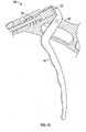
- a surgical instrument 10 which includes a rod holder 12, a sleeve 20 disposed about the rod holder 12, and a pusher rod 22 disposed within the rod holder 12.
- the surgical instrument 10 may further include a handle 42 ( FIGS. 11 and 12 ).
- the surgical instrument 10 can be used by a surgeon to insert and place a rod 18 ( FIG. 11 ) in a patient's body while allowing variation of the angulation of the rod before and during rod insertion and placement.
- Components of the surgical instrument can be made of materials including, but not limited to, titanium, titanium alloys, stainless steel, ceramics, and/or polymers. Some components may be autoclaved and/or chemically sterilized. Components that cannot be autoclaved and/or chemically sterilized may be made of sterile materials.
- the rod holder 12 is hollow and has a pair of opposing yieldable tines 14 for releasably gripping at least a first end 16 of a rod 18.
- each of the tines 14 of the rod holder 12 has an inwardly extending detent 30 on an inner surface 32.
- the detents 30 are shaped so that the first end 16 of the rod 18 can engage pivotally with the rod holder 12 as shown, for example, in FIG. 5 .
- the detents 30 are in axial alignment with one another so as to define a pivot axis 33 ( FIG. 4 ) located between the centres of the two detents 30.
- the rod 18 is rotatable about the pivot axis 33.
- the detents 30 can be spherical, or a partial sphere, pin, cone, or other shape allowing pivotal motion of the rod 18 held between the tines 14.
- the rod 18 may include a pair of recesses 34 (only one of the recesses 34 visible) shaped to receive the detent 30.
- the design and dimensions of the detents 30, recesses 34, and tines 14, and the spring strength of the tines, can be selected to allow for a secure hold on the rod 18 while providing an easy "snap" when the rod 18 and tines 14 are coupled.
- the snap provides the user with a positive feedback indicating successful coupling.
- the first end 16 of the rod 18 is substantially cylindrical in shape where the rod 18 has a flat end surface 35a and a convex side surface 35b which intersect one another to define a curved edge 35c.
- FIG. 7 shows another rod 18a with a first end 16a.
- the first end 16a is similar to the first end 16 of the rod 18 except that the first end 16a of the rod 18a has two opposing flat faces 36 with a recess 34a provided on each of the flat faces 36.
- the flat faces 36 result in the first end 16a of the rod 18a having reduced diameter which in turn allows the rod holder 12 to be reduced in diameter.
- the sleeve 20 is disposed about the rod holder 12 and is slideable between an extended position ( FIG. 3A ) and a retracted position ( FIG. 3B ).
- the sleeve 20 In the extended position, the sleeve 20 is disposed about the tines 14 so as to hold the tines 14 in a rod gripping position when the rod 18 is positioned between the tines 14.
- the sleeve 20 In the retracted position, the sleeve 20 is retracted from the tines 14 leaving the tines 14 outwardly moveable to permit release of the rod 18 from the tines 14.
- the position of the sleeve 20 with respect to the rod holder 12 is adjusted with a sleeve handle 47 provided on a proximal end of the sleeve 20.
- the position of the sleeve 20 with respect to the rod holder 12 may be maintained using a spring plate 43 having a proximal end 45 attached to the rod holder 12.
- a push knob 44 attached to a distal end of the spring plate 43 can be depressed to align a narrowing 53 in the push knob 44 with a neck 55 of the sleeve handle 42, thereby allowing movement of the sleeve handle 42 to reposition the push knob 44 between a first aperture 52 and a second aperture 54, thereby moving the sleeve 20 between the retracted and extended positions, respectively.
- the sleeve 20 is provided with notches 40 and 40' to allow the rod 18 to pivot while secured to the rod holder 12 by the sleeve 20.
- the notch 40' has substantially the same shape as the notch 40, thereby allowing the rod 18 to pivot 180°. In many instances, only a 90° pivot or less is necessary, and greater rod gripping strength may be provided when the size of the notch 40' is minimized to allow rotation only through the notch 40.
- the notch 40' does not extend through the thickness of the sleeve.
- the shape of the notch 40 is made to receive and cradle the rod 18 when the rod 18 is positioned at a 90° angle 28 with respect to the pusher rod 22.
- the rotational position of the sleeve 20 with respect to the rod holder 12 is such that the notch 40 is positioned along the axis 33 connecting the centres of the two detents 30. This position is maintained by the push knob 45 on the rod holder 12 being restricted to either the first or second apertures 52 and 54, respectively, on the sleeve 20.
- the pusher rod 22 is disposed within the rod holder 12 and has a distal end 24 provided with a plurality of rod receiving notches 25a-25c.
- the pusher rod 22 can slide between a retracted position, a holding position, and an extended position.
- the distal end 24 of the pusher rod 22 is positioned so as to disengage from the rod 18 and permit the rod 18 to freely pivot relative to the rod holder 12, as shown in FIG. 5 .
- the distal end 24 of the pusher rod 22 In the holding position ( FIGS. 3A and 9A-9D ), the distal end 24 of the pusher rod 22 is positioned to engage the first end 16 of the rod 18 when the rod 18 is positioned between the tines 14 of the rod holder 12.
- the distal end 24 of the pusher rod 22 is positioned to push and release the rod 18 from the tines 14 of the rod holder 12.
- Each of the rod receiving notches 25a-25c is configured to matingly engage at least a portion of the first end 16 of the rod 18, as shown by way of example in FIGS. 3A and 9A-9D , in such a way that when the rod 18 is gripped by the tines 14 of the rod holder 12 with the sleeve 20 in the extended position and the distal end 24 of the pusher rod 22 is in engagement with the first end 16 of the rod 18, the rod 18 is held at a selected angle 28 with respect to the pusher rod 22 dependent upon in which of the rod receiving notches 25a-25c the rod 18 is disposed.
- the rod receiving notches 25a-25c are configured to engage with a portion of the rod 18 one at a time.
- the rod receiving notches 25a-25c are each defined by a pair of notch surfaces 26a and 26b formed at an angle relative to one another which substantially matches the angle between the end surface 35a and the side surface 35b of the rod 18.
- the angle between the notch surfaces 26a and 26b can vary depending on the angle between the end surface 35a and the side surface 35b of the rod 18.
- the angle between the notch surfaces 26a and 26b can be, for example, about 90°.
- the notch surface 26a and 26b are configured to conform to the contour of a corresponding surface of the rod 18. With the rods 18 and 18a shown in FIGS. 6 and 7 , respectively, the notch surfaces 26a are concave in shape to correspond to the shape of the curved side surface 35b, and the notch surfaces 26b are substantially flat to correspond to the shape of the end surface 35a.
- the intersection of the notch surfaces 26a and 26b defines a trough line 26c.
- the trough lines 26c of the rod receiving notches 25a-25c are parallel to one another. Due to the shapes of the notch surfaces 26a and 26b, the trough lines 26c are curvilinear or concave in shape so as to correspond to the curved shape of the edge 35c of the rod 18.
- the rod receiving notches 25a-25c are provided in the distal end 24 of the pusher rod 22 so that the rod receiving notches 25a-25c are radially oriented about the rod pivot axis 33 at equal angular intervals when the pusher rod 18 is in the holding position. It should be appreciated that while the pusher rod 22 is shown as having three rod receiving notches, the number of rod receiving notches may be varied from one, two, three, or more.
- the distal end 24 of the pusher rod 22 is provided with a pair of lateral end surfaces 55a and 55b ( FIG. 10 ).
- the lateral end surfaces 55a and 55b are arranged in a diametrically opposing relationship with another and configured to conform to the contour of the side surface 35b of the rod 18 so as to matingly engage the rod 18 when the rod 18 is positioned at an angle of about 90° relative to the pusher rod 22 ( FIG. 9A ). More particularly, the lateral end surfaces 55 are concave in shape to mate with the convex shape of side surface 35b of the rod 18.
- the distal end 24 of the pusher rod 22 may be configured to contact the rod 18 at multiple points.
- the lateral end surface 55a intersects the notch surface 26a of the rod receiving notch 25a to define an edge 57a
- the lateral end surface 55b intersects the notch surface 26b of the rod receiving notch 25c to define and edge 57b.
- the edges 57a and 57b are in a diametrically opposing relationship with another.
- the notch surface 26a of the rod receiving notch 25b and the notch surface 26a of the rod receiving notch 25c are in alignment with the edge 57a.
- the side surface 35b of the rod 18 contacts at least a portion of the edge 57a when the rod 18 is positioned in the rod receiving notch 25b and the rod receiving notch 25c to provide another point of supporting contact between the pusher rod 22 and the rod 18.
- the notch surfaces 26b of the rod receiving notches 25a, 25b are in alignment with the edge 57b.
- the end surface 35a of the rod 18 contacts at least a portion of the edge 57b when the rod 18 is positioned in the rod receiving notches 25a, 25b to provide another point of supporting contact between the pusher rod 22 and the rod 18.
- the pusher rod 18 may include a first section 56 which can engage using threads with a second section 58 to facilitate disassembling and cleaning.
- a pin 60 extending from the pusher rod 22 is slideably positioned in slots 62 in the rod holder 12 to maintain the rotational position of the pusher rod 22 with respect to the rod holder 12.
- the handle 42 facilitates a surgeon in inserting and positioning the rod 18 during surgery.
- the handle 42 may be connected to a proximal end of the rod holder 12 and be provided with a lever 46 for pushing the rod 18 from the rod holder 12.
- a spring 50 is provided to bias the pusher rod 22 in the retracted position.
- the surgeon can keep the pusher rod engaged with the rod 18.
- the pusher rod 22 is retracted by the spring 50 and the rod 18 is allowed to pivot.
- the lever 46 of the handle 42 can be used to push the pusher rod 22 toward the extended position disengaging the rod 18 from the rod holder 12.
- the rod holder 12 can then be pulled away from the rod 18 at any angulation.
- the handle 42 can be connected to the rod holder 12 using cylindrical opposing surfaces as shown in FIG. 12 , allowing the handle 42 to be readily connected and removed from the rod holder 12.
- An orientation mark 64 on the rod holder 12 can be positioned in a respective opening 66 on the handle 42 to ensure the proper orientation of the handle 42.
- An eccentric (not shown) on a locking lever 68 on the handle 42 can be used to engage a groove 70 on the rod holder 12 and lock the handle 42 onto the surgical instrument 10. By disengaging the locking lever 68 from the groove 70, the handle 42 can be readily removed.
- the handle 42 can be connected to a second rod holder 12 in order to insert a contra lateral rod 18. Both rod holders 12 can be disconnected after the entire construct is finished. When the handle 42 is disconnected, the rod holder 12 can be held in one hand and pulled away from the rod 18 in a manner similar to a syringe.
- the surgical instrument 10 can be used in any surgical indication requiring stabilization using screw and rod type constructs.
- the presently disclosed surgical instrument 10 can be used in open or minimally invasive surgeries. Additional incisions for the rod insertion are avoided and a controlled rod insertion is provided by allowing changes of the rod angulation with respect to the rod holder.
Landscapes
- Health & Medical Sciences (AREA)
- Orthopedic Medicine & Surgery (AREA)
- Neurology (AREA)
- Life Sciences & Earth Sciences (AREA)
- Surgery (AREA)
- Heart & Thoracic Surgery (AREA)
- Engineering & Computer Science (AREA)
- Biomedical Technology (AREA)
- Nuclear Medicine, Radiotherapy & Molecular Imaging (AREA)
- Medical Informatics (AREA)
- Molecular Biology (AREA)
- Animal Behavior & Ethology (AREA)
- General Health & Medical Sciences (AREA)
- Public Health (AREA)
- Veterinary Medicine (AREA)
- Surgical Instruments (AREA)
Claims (15)
- Instrument chirurgical (10), comprenant :un support de tige (12) qui comporte une paire de fourchons déformables opposés (14) qui sont configurés de manière à ce qu'ils saisissent une tige (18) de façon libérable entre eux ;une gaine (20) qui est disposée autour du support de tige (12), laquelle gaine peut coulisser entre une position étendue dans laquelle la gaine est positionnée autour des fourchons de manière à ce qu'elle maintienne les fourchons dans une position de saisie de tige lorsque la tige est positionnée entre les fourchons, et une position rétractée dans laquelle la gaine est positionnée de telle sorte que les fourchons puissent être déplacés vers l'extérieur de manière à permettre la libération de la tige par rapport aux fourchons ; etune tige de moyen de poussée (22) qui est disposée de façon coulissante à l'intérieur du support de tige, la tige de moyen de poussée comportant une extrémité distale (24) qui est munie d'une pluralité d'encoches de réception de tige (25a, 25b, 25c) qui sont configurées de manière à ce qu'elles engagent au moins une partie d'une extrémité de la tige de telle sorte que lorsque la tige est saisie par les fourchons du support de tige tandis que la gaine est dans la position étendue et que l'extrémité distale de la tige de moyen de poussée est en engagement avec l'extrémité de la tige, la tige soit maintenue selon un angle sélectionné par rapport à la tige de moyen de poussée.
- Instrument chirurgical selon la revendication 1, dans lequel chacune des encoches de réception de tige est définie par au moins une paire de surfaces d'encoche (26a, 26b) qui sont formées selon un angle l'une par rapport à l'autre, dans lequel les surfaces d'encoche s'intersectent de manière à ce qu'elles définissent une ligne de traversée (26c), et dans lequel les lignes de traversée des encoches de réception de tige sont parallèles les unes aux autres.
- Instrument chirurgical selon la revendication 2, dans lequel la ligne de traversée des encoches de réception de tige est curviligne.
- Instrument chirurgical selon la revendication 2 ou la revendication 3, dans lequel la ligne de traversée des encoches de réception de tige est concave.
- Instrument chirurgical selon l'une quelconque des revendications 2 à 4, dans lequel l'angle entre les surfaces d'encoche est d'environ 90 degrés.
- Instrument chirurgical selon l'une quelconque des revendications 2 à 5, dans lequel la paire de surfaces d'encoche est configurée de manière à ce qu'elles épousent le contour d'une surface correspondante (35b) de la tige.
- Instrument chirurgical selon l'une quelconque des revendications 2 à 6, dans lequel l'une des surfaces d'encoche est concave et dans lequel l'autre surface d'encoche est sensiblement plane.
- Instrument chirurgical selon l'une quelconque des revendications 1 à 7, dans lequel les encoches de réception de tige sont orientées radialement.
- Instrument chirurgical selon l'une quelconque des revendications 1 à 8, dans lequel les fourchons coopèrent de manière à ce qu'ils définissent un axe de pivotement de tige (33) et dans lequel les encoches de réception de tige sont orientées radialement autour de l'axe de pivotement de tige lorsque la tige de moyen de poussée est dans la position de maintien.
- Instrument chirurgical selon l'une quelconque des revendications 1 et 5 à 9, dans lequel chacune des encoches de réception de tige est définie par au moins une paire de surfaces d'encoche qui sont formées selon un angle l'une par rapport à l'autre, dans lequel l'extrémité distale de la tige de moyen de poussée comporte une paire de bords diamétralement opposés (57a, 57b), et dans lequel l'une des surfaces d'encoche de chacune des encoches de réception de tige est alignée avec au moins une partie de l'un des bords et l'autre surface d'encoche de chacune des encoches de réception de tige est alignée avec au moins une partie de l'autre bord.
- Instrument chirurgical selon l'une quelconque des revendications 1 à 10, dans lequel la tige de moyen de poussée comporte trois encoches de réception de tige.
- Instrument chirurgical selon l'une quelconque des revendications 1 à 11, dans lequel chacun des fourchons comporte une détente s'étendant vers l'intérieur (30) qui peut s'engager de façon pivotante avec la première extrémité de la tige, et dans lequel chacune des détentes est en alignement axial mutuel avec l'autre détente de manière à définir un axe de pivotement (33).
- Instrument chirurgical selon l'une quelconque des revendications 1 à 12, dans lequel la tige de moyen de poussée peut coulisser entre une position rétractée dans laquelle l'extrémité distale de la tige de moyen de poussée est positionnée de manière à ce qu'elle soit désengagée de la tige de manière à permettre le pivotement de la tige par rapport au support de tige, une position de maintien dans laquelle l'extrémité distale de la tige de moyen de poussée est positionnée de manière à ce qu'elle engage la première extrémité de la tige, et une position étendue dans laquelle l'extrémité distale de la tige de moyen de poussée est positionnée au-delà de la position de maintien de manière à ce qu'elle pousse et ainsi libère la tige vis-à-vis des fourchons du support de tige.
- Instrument chirurgical selon l'une quelconque des revendications 1 à 13, dans lequel la tige de moyen de poussée est sollicitée par poussée en direction de la position rétractée.
- Instrument chirurgical selon la revendication 13 ou la revendication 14, lequel inclut une poignée/un manche (42) qui est fixé(e) au support de tige, la poignée/le manche comportant un levier (46) en association avec la tige de moyen de poussée de manière à déplacer la tige de moyen de poussée depuis la position rétractée jusqu'à la position de maintien et la position étendue.
Applications Claiming Priority (1)
| Application Number | Priority Date | Filing Date | Title |
|---|---|---|---|
| US13/570,010 US9011450B2 (en) | 2012-08-08 | 2012-08-08 | Surgical instrument |
Publications (2)
| Publication Number | Publication Date |
|---|---|
| EP2695582A1 EP2695582A1 (fr) | 2014-02-12 |
| EP2695582B1 true EP2695582B1 (fr) | 2018-03-07 |
Family
ID=48874901
Family Applications (1)
| Application Number | Title | Priority Date | Filing Date |
|---|---|---|---|
| EP13178205.4A Active EP2695582B1 (fr) | 2012-08-08 | 2013-07-26 | Instrument chirurgical |
Country Status (2)
| Country | Link |
|---|---|
| US (1) | US9011450B2 (fr) |
| EP (1) | EP2695582B1 (fr) |
Families Citing this family (11)
| Publication number | Priority date | Publication date | Assignee | Title |
|---|---|---|---|---|
| US9526536B2 (en) * | 2013-10-16 | 2016-12-27 | Spineology Inc. | Articulating rod holder |
| US11478275B2 (en) | 2014-09-17 | 2022-10-25 | Spinal Elements, Inc. | Flexible fastening band connector |
| EP3232961B1 (fr) * | 2014-12-15 | 2022-06-08 | Smith & Nephew, Inc. | Active implants de compression d'une fracture |
| EP3047811B1 (fr) * | 2015-01-15 | 2022-05-18 | K2M, Inc. | Réducteur de tige |
| US9795422B2 (en) * | 2016-01-06 | 2017-10-24 | Aesculap Implant Systems, Llc | Rod inserter, system and method |
| DE102016011521A1 (de) * | 2016-09-23 | 2018-03-29 | Silony Medical International AG | Stabeinbringinstrument mit verstellbarer Stabangulierung |
| US10779866B2 (en) | 2016-12-29 | 2020-09-22 | K2M, Inc. | Rod reducer assembly |
| JP6947928B2 (ja) | 2017-11-13 | 2021-10-13 | ジンマー バイオメット シーエムエフ アンド ソラシック,リミティド ライアビリティ カンパニー | 胸部プレートインプラント及びその使用方法 |
| US11457959B2 (en) * | 2019-05-22 | 2022-10-04 | Spinal Elements, Inc. | Bone tie and bone tie inserter |
| WO2020236229A1 (fr) | 2019-05-22 | 2020-11-26 | Spinal Elements, Inc. | Attache osseuse et dispositif d'insertion d'attache osseuse |
| US20210346065A1 (en) * | 2020-04-09 | 2021-11-11 | Globus Medical, Inc. | Spinal screw |
Family Cites Families (177)
| Publication number | Priority date | Publication date | Assignee | Title |
|---|---|---|---|---|
| US1710092A (en) | 1924-01-29 | 1929-04-23 | James E Hitchcock | Chain tool |
| US2250417A (en) | 1939-12-02 | 1941-07-22 | Zimmer Mfg Company | Fracture reduction and retention device |
| US2333033A (en) | 1943-06-11 | 1943-10-26 | Leslie E Mraz | Bone splint |
| US2373478A (en) | 1943-11-22 | 1945-04-10 | Breeze Corp | Expander tool |
| US3575405A (en) | 1968-08-28 | 1971-04-20 | Emmit B Harding | Parallel bar clamping device |
| US3861432A (en) | 1973-10-29 | 1975-01-21 | Gunter Rothenberger | Work table for clamping against planar surfaces |
| DE3414374C2 (de) | 1984-04-16 | 1986-12-18 | Patrick Dr. 3590 Bad Wildungen Kluger | Vorrichtung zum Einrichten einer Wirbelsäule mit geschädigten Wirbelkörpern |
| DE3711091A1 (de) | 1987-04-02 | 1988-10-13 | Kluger Patrick | Vorrichtung zum einrichten einer wirbelsaeule mit geschaedigten wirbelkoerpern |
| DE3809793A1 (de) | 1988-03-23 | 1989-10-05 | Link Waldemar Gmbh Co | Chirurgischer instrumentensatz |
| US4848368A (en) | 1988-04-25 | 1989-07-18 | Kronner Richard F | Universal external fixation frame assembly |
| US5015247A (en) | 1988-06-13 | 1991-05-14 | Michelson Gary K | Threaded spinal implant |
| US7452359B1 (en) | 1988-06-13 | 2008-11-18 | Warsaw Orthopedic, Inc. | Apparatus for inserting spinal implants |
| AU7139994A (en) | 1988-06-13 | 1995-01-03 | Karlin Technology, Inc. | Apparatus and method of inserting spinal implants |
| US5484437A (en) | 1988-06-13 | 1996-01-16 | Michelson; Gary K. | Apparatus and method of inserting spinal implants |
| US5772661A (en) | 1988-06-13 | 1998-06-30 | Michelson; Gary Karlin | Methods and instrumentation for the surgical correction of human thoracic and lumbar spinal disease from the antero-lateral aspect of the spine |
| FR2650173B1 (fr) | 1989-07-26 | 1991-11-15 | Jbs Sa | Procede et dispositif de redressement, fixation, compression, elongation du rachis |
| GB9014817D0 (en) | 1990-07-04 | 1990-08-22 | Mehdian Seyed M H | Improvements in or relating to apparatus for use in the treatment of spinal disorders |
| US5219349A (en) | 1991-02-15 | 1993-06-15 | Howmedica, Inc. | Spinal fixator reduction frame |
| FR2684866B1 (fr) | 1991-12-12 | 1994-05-13 | Jbs | Perfectionnements aux procedes et aux dispositifs de redressement, fixation, compression, elongation du rachis. |
| GB9217578D0 (en) | 1992-08-19 | 1992-09-30 | Surgicarft Ltd | Surgical implants,etc |
| FR2697743B1 (fr) | 1992-11-09 | 1995-01-27 | Fabrication Mat Orthopedique S | Dispositif d'ostéosynthèse rachidienne applicable notamment aux vertèbres dégénératives. |
| DE4307576C1 (de) | 1993-03-10 | 1994-04-21 | Biedermann Motech Gmbh | Knochenschraube |
| ES2231110T3 (es) | 1993-06-10 | 2005-05-16 | Karlin Technology, Inc. | Separador vertebral. |
| US5702401A (en) | 1993-06-23 | 1997-12-30 | Shaffer; Benjamin | Intra-articular measuring device |
| CA2551185C (fr) | 1994-03-28 | 2007-10-30 | Sdgi Holdings, Inc. | Appareil et methode pour stabilisation vertebrale anterieure |
| ATE461664T1 (de) | 1994-03-28 | 2010-04-15 | Warsaw Orthopedic Inc | Einrichtung zur wirbelsäulenfixation |
| US5529571A (en) | 1995-01-17 | 1996-06-25 | Daniel; Elie C. | Surgical retractor/compressor |
| DE69737756T2 (de) | 1995-03-27 | 2008-01-31 | Warsaw Orthopedic, Inc., Minneapolis | Wirbelsäulenfusionsimplantat |
| US5782919A (en) | 1995-03-27 | 1998-07-21 | Sdgi Holdings, Inc. | Interbody fusion device and method for restoration of normal spinal anatomy |
| CN100396248C (zh) | 1995-06-07 | 2008-06-25 | Sdgi控股有限公司 | 平移式脊骨植入物 |
| DE19549426C2 (de) | 1995-08-11 | 1997-10-09 | Bernhard Zientek | Zwischenwirbelimplantat und Instrument hierfür |
| US5735842A (en) | 1995-09-11 | 1998-04-07 | St. Jude Medical, Inc. | Low profile manipulators for heart valve prostheses |
| US5782830A (en) | 1995-10-16 | 1998-07-21 | Sdgi Holdings, Inc. | Implant insertion device |
| US5676664A (en) | 1995-11-27 | 1997-10-14 | Zimmer, Inc. | Orthopaedic distractor and/or fixator |
| US5797900A (en) | 1996-05-20 | 1998-08-25 | Intuitive Surgical, Inc. | Wrist mechanism for surgical instrument for performing minimally invasive surgery with enhanced dexterity and sensitivity |
| US6712819B2 (en) | 1998-10-20 | 2004-03-30 | St. Francis Medical Technologies, Inc. | Mating insertion instruments for spinal implants and methods of use |
| US6451019B1 (en) | 1998-10-20 | 2002-09-17 | St. Francis Medical Technologies, Inc. | Supplemental spine fixation device and method |
| US6068630A (en) | 1997-01-02 | 2000-05-30 | St. Francis Medical Technologies, Inc. | Spine distraction implant |
| US5860977A (en) | 1997-01-02 | 1999-01-19 | Saint Francis Medical Technologies, Llc | Spine distraction implant and method |
| US6695842B2 (en) | 1997-10-27 | 2004-02-24 | St. Francis Medical Technologies, Inc. | Interspinous process distraction system and method with positionable wing and method |
| US6902566B2 (en) | 1997-01-02 | 2005-06-07 | St. Francis Medical Technologies, Inc. | Spinal implants, insertion instruments, and methods of use |
| US5910141A (en) | 1997-02-12 | 1999-06-08 | Sdgi Holdings, Inc. | Rod introduction apparatus |
| US6226548B1 (en) | 1997-09-24 | 2001-05-01 | Surgical Navigation Technologies, Inc. | Percutaneous registration apparatus and method for use in computer-assisted surgical navigation |
| KR100779258B1 (ko) | 1997-10-27 | 2007-11-27 | 세인트 프랜시스 메디컬 테크놀로지스, 인코포레이티드 | 척추 신연 삽입물 |
| DE19754869C2 (de) | 1997-12-10 | 1999-09-30 | Aesculap Ag & Co Kg | Befestigungselement für Knochenplatten mit zugehörigem Anlegewerkzeug |
| US5957927A (en) | 1998-02-24 | 1999-09-28 | Synthes (Usa) | Bone fixation device introducer |
| EP0940127B1 (fr) | 1998-03-02 | 2003-11-26 | Benoist Girard Sas | Dispositif d'insertion de prothèse |
| DE29806563U1 (de) * | 1998-04-09 | 1998-06-18 | Howmedica GmbH, 24232 Schönkirchen | Pedikelschraube und Montagehilfe dafür |
| US6102934A (en) | 1998-06-02 | 2000-08-15 | Li; Lehmann K. | Anchor tool and method and apparatus for emplacing anchor in a borehole |
| US7189234B2 (en) | 1998-10-20 | 2007-03-13 | St. Francis Medical Technologies, Inc. | Interspinous process implant sizer and distractor with a split head and size indicator and method |
| US6156037A (en) | 1998-10-28 | 2000-12-05 | Sdgi Holdings, Inc. | Anterior lateral spine cage-plate fixation device and technique |
| DE60044258D1 (de) | 1999-01-25 | 2010-06-02 | Warsaw Orthopedic Inc | Instrument zur schaffung eines zwischenwirbelraumes für die aufnahme eines implantates |
| DE19903762C1 (de) | 1999-01-30 | 2000-11-16 | Aesculap Ag & Co Kg | Chirurgisches Instrument zum Einführen von Zwischenwirbelimplantaten |
| US6607530B1 (en) | 1999-05-10 | 2003-08-19 | Highgate Orthopedics, Inc. | Systems and methods for spinal fixation |
| JP2003509118A (ja) | 1999-09-14 | 2003-03-11 | スパイン ソリューションズ インコーポレイテッド | 椎間インプラント用挿入器具 |
| US6530929B1 (en) | 1999-10-20 | 2003-03-11 | Sdgi Holdings, Inc. | Instruments for stabilization of bony structures |
| US7938836B2 (en) | 2003-10-23 | 2011-05-10 | Trans1, Inc. | Driver assembly for simultaneous axial delivery of spinal implants |
| US6224598B1 (en) | 2000-02-16 | 2001-05-01 | Roger P. Jackson | Bone screw threaded plug closure with central set screw |
| ES2302724T3 (es) | 2000-02-22 | 2008-08-01 | Warsaw Orthopedic, Inc. | Implante espinal e instrumento de insercion. |
| DE10011678B4 (de) | 2000-03-10 | 2007-07-26 | Richard Wolf Gmbh | Chirurgisches Instrument zum Applizieren von Implantaten |
| JP3936118B2 (ja) | 2000-03-28 | 2007-06-27 | 昭和医科工業株式会社 | ロッドグリッパー |
| DE60136980D1 (de) | 2000-03-28 | 2009-01-22 | Showa Ika Kogyo Co Ltd | Wirbelsäulenimplantat, Antriebswerkzeug und Mutterführung |
| US6746443B1 (en) | 2000-07-27 | 2004-06-08 | Intuitive Surgical Inc. | Roll-pitch-roll surgical tool |
| DE10115014A1 (de) | 2001-03-27 | 2002-10-24 | Biedermann Motech Gmbh | Verankerungselement |
| US20030040746A1 (en) | 2001-07-20 | 2003-02-27 | Mitchell Margaret E. | Spinal stabilization system and method |
| DE10136129A1 (de) | 2001-07-27 | 2003-02-20 | Biedermann Motech Gmbh | Knochenschraube und Befestigungswerkzeug für diese |
| DE10157969C1 (de) | 2001-11-27 | 2003-02-06 | Biedermann Motech Gmbh | Element mit einem Schaft und einem damit verbundenen Halteelement zum Verbinden mit einem Stab |
| DE10157814B4 (de) | 2001-11-27 | 2004-12-02 | Biedermann Motech Gmbh | Verschlußeinrichtung zum Sichern eines stabförmigen Elements in einem mit einem Schaft verbundenen Halteelement |
| AU2002360783A1 (en) | 2001-12-27 | 2003-07-24 | Osteotech Inc. | Orthopedic/neurosurgical system and method for securing vertebral bone facets |
| US9101422B2 (en) | 2002-02-01 | 2015-08-11 | Zimmer Spine, Inc. | Spinal plate system for stabilizing a portion of a spine |
| US20040019353A1 (en) | 2002-02-01 | 2004-01-29 | Freid James M. | Spinal plate system for stabilizing a portion of a spine |
| US7011658B2 (en) | 2002-03-04 | 2006-03-14 | Sdgi Holdings, Inc. | Devices and methods for spinal compression and distraction |
| US6660006B2 (en) * | 2002-04-17 | 2003-12-09 | Stryker Spine | Rod persuader |
| US7572276B2 (en) | 2002-05-06 | 2009-08-11 | Warsaw Orthopedic, Inc. | Minimally invasive instruments and methods for inserting implants |
| US6689132B2 (en) | 2002-05-15 | 2004-02-10 | Spineco, Inc. | Spinal implant insertion tool |
| US7278995B2 (en) * | 2002-06-04 | 2007-10-09 | Howmedica Osteonics Corp. | Apparatus for securing a spinal rod system |
| US7306603B2 (en) | 2002-08-21 | 2007-12-11 | Innovative Spinal Technologies | Device and method for percutaneous placement of lumbar pedicle screws and connecting rods |
| US7862597B2 (en) | 2002-08-22 | 2011-01-04 | Warsaw Orthopedic, Inc. | System for stabilizing a portion of the spine |
| DE50202334D1 (de) | 2002-10-25 | 2005-03-31 | Brainlab Ag | Vorrichtung zum Positionieren eines Elements, zum Beispiel in der Wirbelsäule |
| US9539012B2 (en) | 2002-10-30 | 2017-01-10 | Zimmer Spine, Inc. | Spinal stabilization systems with quick-connect sleeve assemblies for use in surgical procedures |
| ES2629625T3 (es) | 2002-10-30 | 2017-08-11 | Zimmer Spine, Inc. | Sistema de estabilización espinal por inserción |
| US6945974B2 (en) | 2003-07-07 | 2005-09-20 | Aesculap Inc. | Spinal stabilization implant and method of application |
| DE10330699B3 (de) | 2003-07-08 | 2005-02-17 | Aesculap Ag & Co. Kg | Chirurgisches Instrument zum Handhaben eines Implantats |
| US7320689B2 (en) | 2003-07-15 | 2008-01-22 | Cervitech, Inc. | Multi-part cervical endoprosthesis with insertion instrument |
| US20050021040A1 (en) | 2003-07-21 | 2005-01-27 | Rudolf Bertagnoli | Vertebral retainer-distracter and method of using same |
| US7252673B2 (en) | 2003-09-10 | 2007-08-07 | Warsaw Orthopedic, Inc. | Devices and methods for inserting spinal implants |
| US8002798B2 (en) | 2003-09-24 | 2011-08-23 | Stryker Spine | System and method for spinal implant placement |
| WO2005034781A1 (fr) | 2003-09-29 | 2005-04-21 | Promethean Surgical Devices Llc | Dispositifs et procedes de reparation de la colonne vertebrale |
| US7967826B2 (en) | 2003-10-21 | 2011-06-28 | Theken Spine, Llc | Connector transfer tool for internal structure stabilization systems |
| US7588588B2 (en) | 2003-10-21 | 2009-09-15 | Innovative Spinal Technologies | System and method for stabilizing of internal structures |
| US7905907B2 (en) | 2003-10-21 | 2011-03-15 | Theken Spine, Llc | Internal structure stabilization system for spanning three or more structures |
| WO2005039392A2 (fr) | 2003-10-22 | 2005-05-06 | Endius Incorporated | Methode et instrument chirurgical permettant d'inserer un element longitudinal |
| US7341587B2 (en) | 2003-11-20 | 2008-03-11 | Warsaw Orthopedic, Inc. | Methods and devices for inserting and engaging vertebral implants in minimally invasive procedures |
| US7481839B2 (en) | 2003-12-02 | 2009-01-27 | Kyphon Sarl | Bioresorbable interspinous process implant for use with intervertebral disk remediation or replacement implants and procedures |
| US7648506B2 (en) | 2003-12-16 | 2010-01-19 | Depuy Acromed, Inc. | Pivoting implant holder |
| US7527638B2 (en) | 2003-12-16 | 2009-05-05 | Depuy Spine, Inc. | Methods and devices for minimally invasive spinal fixation element placement |
| WO2005060534A2 (fr) | 2003-12-16 | 2005-07-07 | Depuy Spine, Inc. | Procedes et dispositifs pour placer un element de fixation vertebrale avec effraction minimale |
| US7648507B2 (en) | 2003-12-16 | 2010-01-19 | Depuy Acromed, Inc. | Pivoting implant holder |
| AU2005213351B2 (en) | 2004-02-06 | 2011-02-17 | Depuy Spine, Inc. | Devices and methods for inserting a spinal fixation element |
| DE102004010380A1 (de) | 2004-03-03 | 2005-09-22 | Biedermann Motech Gmbh | Verankerungselement und Stabilisierungseinrichtung zur dynamischen Stabilisierung von Wirbeln bzw. Knochen mit einem solchen Verankerungselement |
| JP4213609B2 (ja) * | 2004-03-09 | 2009-01-21 | 昭和医科工業株式会社 | ロッド固定用補助器具 |
| US20050203532A1 (en) | 2004-03-12 | 2005-09-15 | Sdgi Holdings, Inc. | Technique and instrumentation for intervertebral prosthesis implantation using independent landmarks |
| US7776051B2 (en) | 2004-05-03 | 2010-08-17 | Theken Spine, Llc | System and method for displacement of bony structures |
| US20050277934A1 (en) | 2004-06-10 | 2005-12-15 | Vardiman Arnold B | Rod delivery device and method |
| US7717938B2 (en) | 2004-08-27 | 2010-05-18 | Depuy Spine, Inc. | Dual rod cross connectors and inserter tools |
| US7883510B2 (en) | 2004-08-27 | 2011-02-08 | Depuy Spine, Inc. | Vertebral staples and insertion tools |
| DE202004014120U1 (de) | 2004-09-08 | 2004-11-11 | Aesculap Ag & Co. Kg | Chirurgisches Instrument |
| US7666189B2 (en) | 2004-09-29 | 2010-02-23 | Synthes Usa, Llc | Less invasive surgical system and methods |
| JP4831435B2 (ja) | 2004-10-08 | 2011-12-07 | ウォーソー・オーソペディック・インコーポレーテッド | 内部接続椎体間ケージ挿入用の器具、及び装置 |
| WO2006044920A2 (fr) | 2004-10-19 | 2006-04-27 | Osteotech, Inc. | Instruments reglables pour insertion d'implant spinal |
| US8152837B2 (en) | 2004-10-20 | 2012-04-10 | The Board Of Trustees Of The Leland Stanford Junior University | Systems and methods for posterior dynamic stabilization of the spine |
| US8425559B2 (en) | 2004-10-20 | 2013-04-23 | Vertiflex, Inc. | Systems and methods for posterior dynamic stabilization of the spine |
| US7569061B2 (en) | 2004-11-16 | 2009-08-04 | Innovative Spinal Technologies, Inc. | Off-axis anchor guidance system |
| WO2006057837A1 (fr) | 2004-11-23 | 2006-06-01 | Jackson Roger P | Structure d'accrochage pour outil de fixation spinale |
| US7811288B2 (en) | 2004-12-02 | 2010-10-12 | Zimmer Spine, Inc. | Instruments and methods for adjusting separation distance of vertebral bodies with a minimally invasive spinal stabilization procedure |
| JP4977038B2 (ja) | 2005-02-17 | 2012-07-18 | カイフォン・ソシエテ・ア・レスポンサビリテ・リミテ | 経皮的脊椎インプラントおよび方法 |
| US8096994B2 (en) | 2005-02-17 | 2012-01-17 | Kyphon Sarl | Percutaneous spinal implants and methods |
| EP1858422A4 (fr) | 2005-02-23 | 2011-12-28 | Pioneer Surgical Technology Inc | Systeme chirurgical peu invasif |
| US7951175B2 (en) | 2005-03-04 | 2011-05-31 | Depuy Spine, Inc. | Instruments and methods for manipulating a vertebra |
| US7763078B2 (en) | 2005-03-28 | 2010-07-27 | Warsaw Orthopedic, Inc. | Spinal device including lateral approach |
| US7758617B2 (en) | 2005-04-27 | 2010-07-20 | Globus Medical, Inc. | Percutaneous vertebral stabilization system |
| US7578822B2 (en) | 2005-04-29 | 2009-08-25 | Warsaw Orthopedic, Inc. | Instrument for compression or distraction |
| US7871424B2 (en) | 2005-05-23 | 2011-01-18 | Custom Spine, Inc. | Spinal rod inserter |
| US7749232B2 (en) | 2005-05-24 | 2010-07-06 | Anthony Salerni | Electromagnetically guided spinal rod system and related methods |
| DE602005002477T2 (de) | 2005-07-12 | 2008-01-17 | Biedermann Motech Gmbh | Knochenverankerungsvorrichtung |
| US7753938B2 (en) | 2005-08-05 | 2010-07-13 | Synthes Usa, Llc | Apparatus for treating spinal stenosis |
| US7909830B2 (en) | 2005-08-25 | 2011-03-22 | Synthes Usa, Llc | Methods of spinal fixation and instrumentation |
| US20070083210A1 (en) | 2005-09-16 | 2007-04-12 | Zimmer Spine, Inc. | Apparatus and method for minimally invasive spine surgery |
| US20100100138A1 (en) | 2005-09-21 | 2010-04-22 | Reynolds Joseph E | Endoscopic Insturments and Mehod for Delivery of Spinal Implant |
| US8852270B2 (en) | 2007-11-15 | 2014-10-07 | Cardiosolutions, Inc. | Implant delivery system and method |
| WO2007059207A2 (fr) | 2005-11-14 | 2007-05-24 | Abdou M S | Dispositif et procede pour le placement de fixateurs vertebraux |
| US7497869B2 (en) | 2006-01-27 | 2009-03-03 | Warsaw Orthopedic, Inc. | Methods and devices for a minimally invasive placement of a rod within a patient |
| US7520879B2 (en) | 2006-02-07 | 2009-04-21 | Warsaw Orthopedic, Inc. | Surgical instruments and techniques for percutaneous placement of spinal stabilization elements |
| ES2333183T3 (es) | 2006-03-31 | 2010-02-17 | Biedermann Motech Gmbh | Sistema de fijacion para dispositivos de anclaje oseo. |
| CA2648204C (fr) | 2006-04-11 | 2014-07-22 | Synthes (U.S.A.) | Systeme de fixation a invasion minimale |
| DE102007018860B4 (de) | 2006-04-28 | 2023-01-05 | Paradigm Spine L.L.C. | Instrumentensystem für die Verwendung mit einem interspinalen Implantat |
| EP2329779A1 (fr) | 2006-06-16 | 2011-06-08 | Kyphon SÀRL | Implants rachidiens percutanés |
| US20080077155A1 (en) | 2006-09-25 | 2008-03-27 | Jennifer Diederich | System and method for displacement of bony structures |
| US7686809B2 (en) | 2006-09-25 | 2010-03-30 | Stryker Spine | Rod inserter and rod with reduced diameter end |
| US8162952B2 (en) | 2006-09-26 | 2012-04-24 | Ebi, Llc | Percutaneous instrument assembly |
| US8197488B2 (en) | 2006-10-16 | 2012-06-12 | Depuy Spine, Inc. | Automatic locking casper distractor |
| WO2009094493A2 (fr) | 2006-11-03 | 2009-07-30 | Innovative Spine | Systèmes et procédés d'accès au rachis |
| US7967821B2 (en) | 2006-11-20 | 2011-06-28 | Depuy Spine, Inc. | Break-off screw extension removal tools |
| WO2008085445A2 (fr) | 2007-01-05 | 2008-07-17 | Collabcom5, Llc | Implant interépineux, outils et procédés d'implantation |
| WO2008098054A2 (fr) | 2007-02-06 | 2008-08-14 | Pioneer Surgical Technology, Inc. | Dispositifs d'implant intervertébral et procédés pour leur insertion |
| US8372121B2 (en) | 2007-02-08 | 2013-02-12 | Warsaw Orthopedic, Inc. | Adjustable coupling systems for spinal stabilization members |
| EP2124777A4 (fr) | 2007-02-21 | 2013-06-05 | Benvenue Medical Inc | Dispositif pour traiter le rachis |
| US20080255567A1 (en) | 2007-04-10 | 2008-10-16 | Joseph Accordino | Spinal distraction system |
| US20090048675A1 (en) | 2007-04-25 | 2009-02-19 | Bhatnagar Mohit K | Spinal Fusion Implants with Selectively Applied Bone Growth Promoting Agent |
| BRPI0809874A2 (pt) | 2007-05-01 | 2014-09-30 | Spinal Simplicity Llc | Implante espinal, implante de processo interespinal para a colocação em um espaço de processo interespinal entre processos espinais de níveis de disco sintomáticos e método de colocação unilateral de um implante |
| US9173686B2 (en) | 2007-05-09 | 2015-11-03 | Ebi, Llc | Interspinous implant |
| FR2916956B1 (fr) | 2007-06-08 | 2012-12-14 | Ldr Medical | Cage intersomatique,prothese intervertebrale,dispositif d'ancrage et instrumentation d'implantation |
| US8556944B2 (en) | 2007-07-31 | 2013-10-15 | Stryker Spine | System and method for vertebral body plating |
| EP2923664B1 (fr) | 2007-10-17 | 2019-01-02 | ARO Medical ApS | Systèmes et appareils de stabilisation de torsion |
| WO2009055026A1 (fr) | 2007-10-23 | 2009-04-30 | Alphatec Spine, Inc. | Systèmes et méthodes de fixation spinale |
| WO2009055541A1 (fr) | 2007-10-23 | 2009-04-30 | K2M, Inc. | Outil d'insertion d'implant |
| US8394109B2 (en) | 2007-10-23 | 2013-03-12 | Alphatec Spine, Inc. | Systems and methods for spinal fixation |
| DE102007052799A1 (de) | 2007-11-02 | 2009-05-07 | Taurus Gmbh & Co.Kg. | Implantat |
| US8961571B2 (en) | 2007-11-19 | 2015-02-24 | David Lee | Method and apparatus for spinal facet joint fusion using irregularly shaped cortical bone implants |
| US8480680B2 (en) | 2007-12-07 | 2013-07-09 | Adam Lewis | Spinal decompression system and method |
| US8235997B2 (en) * | 2008-01-29 | 2012-08-07 | Pioneer Surgical Technology, Inc. | Rod locking instrument |
| US8900248B2 (en) | 2008-06-13 | 2014-12-02 | The University Of Toledo | Insertion assembly for minimally invasive spinal surgery |
| US8197512B1 (en) | 2008-07-16 | 2012-06-12 | Zimmer Spine, Inc. | System and method for spine stabilization using resilient inserts |
| US8287546B2 (en) | 2008-07-31 | 2012-10-16 | Zimmer Spine, Inc. | Surgical instrument with integrated compression and distraction mechanisms |
| US9066763B2 (en) | 2008-07-31 | 2015-06-30 | Zimmer Spine, Inc. | Surgical instrument with integrated reduction and distraction mechanisms |
| US8900238B2 (en) | 2009-03-27 | 2014-12-02 | Globus Medical, Inc. | Devices and methods for inserting a vertebral fixation member |
| US9161787B2 (en) | 2009-04-23 | 2015-10-20 | The Johns Hopkins University | Vertebral body reduction instrument and methods related thereto |
| CN101920499B (zh) | 2009-06-12 | 2014-08-13 | 鸿富锦精密工业(深圳)有限公司 | 夹持装置 |
| US20100331849A1 (en) | 2009-06-30 | 2010-12-30 | Paradigm Spine Llc | Spine distraction and compression instrument |
| US20110166610A1 (en) | 2009-08-07 | 2011-07-07 | Moti Altarac | Systems and methods for stabilization of bone structures, including thorocolumbar stabilization systems and methods |
| KR100942226B1 (ko) | 2009-09-30 | 2010-02-16 | 주식회사 지에스메디칼 | 로드 홀더 및 이를 이용하는 척추용 최소 침습 수술 시스템 |
| US20110093014A1 (en) | 2009-10-19 | 2011-04-21 | Zimmer Spine, Inc. | Rod with Removable End and Inserter Therefor |
| AU2011252871B2 (en) | 2010-05-14 | 2015-07-30 | Beacon Biomedical, Llc | Bone fixation rod and implantation device for insertion thereof |
| US8512383B2 (en) * | 2010-06-18 | 2013-08-20 | Spine Wave, Inc. | Method of percutaneously fixing a connecting rod to a spine |
| US8454664B2 (en) | 2010-06-18 | 2013-06-04 | Spine Wave, Inc. | Method for fixing a connecting rod to a thoracic spine |
| US8206395B2 (en) * | 2010-06-18 | 2012-06-26 | Spine Wave, Inc. | Surgical instrument and method for the distraction or compression of bones |
| WO2012018792A1 (fr) | 2010-08-02 | 2012-02-09 | Synthes Usa, Llc | Système d'implant orthopédique |
-
2012
- 2012-08-08 US US13/570,010 patent/US9011450B2/en active Active
-
2013
- 2013-07-26 EP EP13178205.4A patent/EP2695582B1/fr active Active
Non-Patent Citations (1)
| Title |
|---|
| None * |
Also Published As
| Publication number | Publication date |
|---|---|
| US20140046388A1 (en) | 2014-02-13 |
| EP2695582A1 (fr) | 2014-02-12 |
| US9011450B2 (en) | 2015-04-21 |
Similar Documents
| Publication | Publication Date | Title |
|---|---|---|
| EP2695582B1 (fr) | Instrument chirurgical | |
| US11812940B2 (en) | Minimally open interbody access retraction device and surgical method | |
| US20230136167A1 (en) | Patient-mounted surgical retractor | |
| US12383323B2 (en) | Inserter guide and driver system | |
| CN101489497B (zh) | 微创固定系统 | |
| CN102026584B (zh) | 具有复位功能的扭转位矫正器具 | |
| CN111093540B (zh) | 模块化外科器械和相关方法 | |
| CN102413776B (zh) | 脊骨固定元件旋转装置 | |
| US7909830B2 (en) | Methods of spinal fixation and instrumentation | |
| JP6660398B2 (ja) | 外科的開創器システム及び方法 | |
| US20120296172A1 (en) | Surgical retractor apparatus and method | |
| US9498261B2 (en) | Laminar hook insertion device | |
| US20190090979A1 (en) | Patient-mounted surgical support | |
| US20190053830A1 (en) | Taper lock hook | |
| US10709431B2 (en) | Laparoscopic devices and related methods | |
| EP4008280A1 (fr) | Dérotateurs articulés pour systèmes vertébraux de déformation | |
| EP3684269B1 (fr) | Écarteur chirurgical monté sur le patient | |
| US20070233184A1 (en) | Medical instrument for grasping surgical implant rods | |
| US12551356B2 (en) | Universal lateral pivoting handle |
Legal Events
| Date | Code | Title | Description |
|---|---|---|---|
| AK | Designated contracting states |
Kind code of ref document: A1 Designated state(s): AL AT BE BG CH CY CZ DE DK EE ES FI FR GB GR HR HU IE IS IT LI LT LU LV MC MK MT NL NO PL PT RO RS SE SI SK SM TR |
|
| AX | Request for extension of the european patent |
Extension state: BA ME |
|
| PUAI | Public reference made under article 153(3) epc to a published international application that has entered the european phase |
Free format text: ORIGINAL CODE: 0009012 |
|
| 17P | Request for examination filed |
Effective date: 20140808 |
|
| RBV | Designated contracting states (corrected) |
Designated state(s): AL AT BE BG CH CY CZ DE DK EE ES FI FR GB GR HR HU IE IS IT LI LT LU LV MC MK MT NL NO PL PT RO RS SE SI SK SM TR |
|
| 17Q | First examination report despatched |
Effective date: 20160331 |
|
| GRAP | Despatch of communication of intention to grant a patent |
Free format text: ORIGINAL CODE: EPIDOSNIGR1 |
|
| STAA | Information on the status of an ep patent application or granted ep patent |
Free format text: STATUS: GRANT OF PATENT IS INTENDED |
|
| INTG | Intention to grant announced |
Effective date: 20171002 |
|
| GRAS | Grant fee paid |
Free format text: ORIGINAL CODE: EPIDOSNIGR3 |
|
| GRAA | (expected) grant |
Free format text: ORIGINAL CODE: 0009210 |
|
| STAA | Information on the status of an ep patent application or granted ep patent |
Free format text: STATUS: THE PATENT HAS BEEN GRANTED |
|
| AK | Designated contracting states |
Kind code of ref document: B1 Designated state(s): AL AT BE BG CH CY CZ DE DK EE ES FI FR GB GR HR HU IE IS IT LI LT LU LV MC MK MT NL NO PL PT RO RS SE SI SK SM TR |
|
| REG | Reference to a national code |
Ref country code: GB Ref legal event code: FG4D |
|
| REG | Reference to a national code |
Ref country code: CH Ref legal event code: EP Ref country code: CH Ref legal event code: NV Representative=s name: E. BLUM AND CO. AG PATENT- UND MARKENANWAELTE , CH Ref country code: AT Ref legal event code: REF Ref document number: 975686 Country of ref document: AT Kind code of ref document: T Effective date: 20180315 |
|
| REG | Reference to a national code |
Ref country code: IE Ref legal event code: FG4D |
|
| REG | Reference to a national code |
Ref country code: DE Ref legal event code: R096 Ref document number: 602013033954 Country of ref document: DE |
|
| REG | Reference to a national code |
Ref country code: NL Ref legal event code: MP Effective date: 20180307 |
|
| REG | Reference to a national code |
Ref country code: LT Ref legal event code: MG4D |
|
| PG25 | Lapsed in a contracting state [announced via postgrant information from national office to epo] |
Ref country code: LT Free format text: LAPSE BECAUSE OF FAILURE TO SUBMIT A TRANSLATION OF THE DESCRIPTION OR TO PAY THE FEE WITHIN THE PRESCRIBED TIME-LIMIT Effective date: 20180307 Ref country code: CY Free format text: LAPSE BECAUSE OF FAILURE TO SUBMIT A TRANSLATION OF THE DESCRIPTION OR TO PAY THE FEE WITHIN THE PRESCRIBED TIME-LIMIT Effective date: 20180307 Ref country code: NO Free format text: LAPSE BECAUSE OF FAILURE TO SUBMIT A TRANSLATION OF THE DESCRIPTION OR TO PAY THE FEE WITHIN THE PRESCRIBED TIME-LIMIT Effective date: 20180607 Ref country code: FI Free format text: LAPSE BECAUSE OF FAILURE TO SUBMIT A TRANSLATION OF THE DESCRIPTION OR TO PAY THE FEE WITHIN THE PRESCRIBED TIME-LIMIT Effective date: 20180307 Ref country code: ES Free format text: LAPSE BECAUSE OF FAILURE TO SUBMIT A TRANSLATION OF THE DESCRIPTION OR TO PAY THE FEE WITHIN THE PRESCRIBED TIME-LIMIT Effective date: 20180307 Ref country code: HR Free format text: LAPSE BECAUSE OF FAILURE TO SUBMIT A TRANSLATION OF THE DESCRIPTION OR TO PAY THE FEE WITHIN THE PRESCRIBED TIME-LIMIT Effective date: 20180307 |
|
| REG | Reference to a national code |
Ref country code: AT Ref legal event code: MK05 Ref document number: 975686 Country of ref document: AT Kind code of ref document: T Effective date: 20180307 |
|
| PG25 | Lapsed in a contracting state [announced via postgrant information from national office to epo] |
Ref country code: BG Free format text: LAPSE BECAUSE OF FAILURE TO SUBMIT A TRANSLATION OF THE DESCRIPTION OR TO PAY THE FEE WITHIN THE PRESCRIBED TIME-LIMIT Effective date: 20180607 Ref country code: RS Free format text: LAPSE BECAUSE OF FAILURE TO SUBMIT A TRANSLATION OF THE DESCRIPTION OR TO PAY THE FEE WITHIN THE PRESCRIBED TIME-LIMIT Effective date: 20180307 Ref country code: SE Free format text: LAPSE BECAUSE OF FAILURE TO SUBMIT A TRANSLATION OF THE DESCRIPTION OR TO PAY THE FEE WITHIN THE PRESCRIBED TIME-LIMIT Effective date: 20180307 Ref country code: LV Free format text: LAPSE BECAUSE OF FAILURE TO SUBMIT A TRANSLATION OF THE DESCRIPTION OR TO PAY THE FEE WITHIN THE PRESCRIBED TIME-LIMIT Effective date: 20180307 Ref country code: GR Free format text: LAPSE BECAUSE OF FAILURE TO SUBMIT A TRANSLATION OF THE DESCRIPTION OR TO PAY THE FEE WITHIN THE PRESCRIBED TIME-LIMIT Effective date: 20180608 |
|
| PG25 | Lapsed in a contracting state [announced via postgrant information from national office to epo] |
Ref country code: IT Free format text: LAPSE BECAUSE OF FAILURE TO SUBMIT A TRANSLATION OF THE DESCRIPTION OR TO PAY THE FEE WITHIN THE PRESCRIBED TIME-LIMIT Effective date: 20180307 Ref country code: PL Free format text: LAPSE BECAUSE OF FAILURE TO SUBMIT A TRANSLATION OF THE DESCRIPTION OR TO PAY THE FEE WITHIN THE PRESCRIBED TIME-LIMIT Effective date: 20180307 Ref country code: EE Free format text: LAPSE BECAUSE OF FAILURE TO SUBMIT A TRANSLATION OF THE DESCRIPTION OR TO PAY THE FEE WITHIN THE PRESCRIBED TIME-LIMIT Effective date: 20180307 Ref country code: RO Free format text: LAPSE BECAUSE OF FAILURE TO SUBMIT A TRANSLATION OF THE DESCRIPTION OR TO PAY THE FEE WITHIN THE PRESCRIBED TIME-LIMIT Effective date: 20180307 Ref country code: NL Free format text: LAPSE BECAUSE OF FAILURE TO SUBMIT A TRANSLATION OF THE DESCRIPTION OR TO PAY THE FEE WITHIN THE PRESCRIBED TIME-LIMIT Effective date: 20180307 Ref country code: AL Free format text: LAPSE BECAUSE OF FAILURE TO SUBMIT A TRANSLATION OF THE DESCRIPTION OR TO PAY THE FEE WITHIN THE PRESCRIBED TIME-LIMIT Effective date: 20180307 |
|
| PG25 | Lapsed in a contracting state [announced via postgrant information from national office to epo] |
Ref country code: AT Free format text: LAPSE BECAUSE OF FAILURE TO SUBMIT A TRANSLATION OF THE DESCRIPTION OR TO PAY THE FEE WITHIN THE PRESCRIBED TIME-LIMIT Effective date: 20180307 Ref country code: SM Free format text: LAPSE BECAUSE OF FAILURE TO SUBMIT A TRANSLATION OF THE DESCRIPTION OR TO PAY THE FEE WITHIN THE PRESCRIBED TIME-LIMIT Effective date: 20180307 Ref country code: SK Free format text: LAPSE BECAUSE OF FAILURE TO SUBMIT A TRANSLATION OF THE DESCRIPTION OR TO PAY THE FEE WITHIN THE PRESCRIBED TIME-LIMIT Effective date: 20180307 Ref country code: CZ Free format text: LAPSE BECAUSE OF FAILURE TO SUBMIT A TRANSLATION OF THE DESCRIPTION OR TO PAY THE FEE WITHIN THE PRESCRIBED TIME-LIMIT Effective date: 20180307 |
|
| REG | Reference to a national code |
Ref country code: DE Ref legal event code: R097 Ref document number: 602013033954 Country of ref document: DE |
|
| PG25 | Lapsed in a contracting state [announced via postgrant information from national office to epo] |
Ref country code: PT Free format text: LAPSE BECAUSE OF FAILURE TO SUBMIT A TRANSLATION OF THE DESCRIPTION OR TO PAY THE FEE WITHIN THE PRESCRIBED TIME-LIMIT Effective date: 20180709 |
|
| PLBE | No opposition filed within time limit |
Free format text: ORIGINAL CODE: 0009261 |
|
| STAA | Information on the status of an ep patent application or granted ep patent |
Free format text: STATUS: NO OPPOSITION FILED WITHIN TIME LIMIT |
|
| PG25 | Lapsed in a contracting state [announced via postgrant information from national office to epo] |
Ref country code: DK Free format text: LAPSE BECAUSE OF FAILURE TO SUBMIT A TRANSLATION OF THE DESCRIPTION OR TO PAY THE FEE WITHIN THE PRESCRIBED TIME-LIMIT Effective date: 20180307 |
|
| 26N | No opposition filed |
Effective date: 20181210 |
|
| PG25 | Lapsed in a contracting state [announced via postgrant information from national office to epo] |
Ref country code: SI Free format text: LAPSE BECAUSE OF FAILURE TO SUBMIT A TRANSLATION OF THE DESCRIPTION OR TO PAY THE FEE WITHIN THE PRESCRIBED TIME-LIMIT Effective date: 20180307 |
|
| PG25 | Lapsed in a contracting state [announced via postgrant information from national office to epo] |
Ref country code: MC Free format text: LAPSE BECAUSE OF FAILURE TO SUBMIT A TRANSLATION OF THE DESCRIPTION OR TO PAY THE FEE WITHIN THE PRESCRIBED TIME-LIMIT Effective date: 20180307 Ref country code: LU Free format text: LAPSE BECAUSE OF NON-PAYMENT OF DUE FEES Effective date: 20180726 |
|
| REG | Reference to a national code |
Ref country code: BE Ref legal event code: MM Effective date: 20180731 |
|
| REG | Reference to a national code |
Ref country code: IE Ref legal event code: MM4A |
|
| PG25 | Lapsed in a contracting state [announced via postgrant information from national office to epo] |
Ref country code: IE Free format text: LAPSE BECAUSE OF NON-PAYMENT OF DUE FEES Effective date: 20180726 Ref country code: FR Free format text: LAPSE BECAUSE OF NON-PAYMENT OF DUE FEES Effective date: 20180731 |
|
| PG25 | Lapsed in a contracting state [announced via postgrant information from national office to epo] |
Ref country code: BE Free format text: LAPSE BECAUSE OF NON-PAYMENT OF DUE FEES Effective date: 20180731 |
|
| PG25 | Lapsed in a contracting state [announced via postgrant information from national office to epo] |
Ref country code: MT Free format text: LAPSE BECAUSE OF NON-PAYMENT OF DUE FEES Effective date: 20180726 |
|
| PG25 | Lapsed in a contracting state [announced via postgrant information from national office to epo] |
Ref country code: TR Free format text: LAPSE BECAUSE OF FAILURE TO SUBMIT A TRANSLATION OF THE DESCRIPTION OR TO PAY THE FEE WITHIN THE PRESCRIBED TIME-LIMIT Effective date: 20180307 |
|
| PG25 | Lapsed in a contracting state [announced via postgrant information from national office to epo] |
Ref country code: HU Free format text: LAPSE BECAUSE OF FAILURE TO SUBMIT A TRANSLATION OF THE DESCRIPTION OR TO PAY THE FEE WITHIN THE PRESCRIBED TIME-LIMIT; INVALID AB INITIO Effective date: 20130726 |
|
| PG25 | Lapsed in a contracting state [announced via postgrant information from national office to epo] |
Ref country code: MK Free format text: LAPSE BECAUSE OF NON-PAYMENT OF DUE FEES Effective date: 20180307 |
|
| PG25 | Lapsed in a contracting state [announced via postgrant information from national office to epo] |
Ref country code: IS Free format text: LAPSE BECAUSE OF FAILURE TO SUBMIT A TRANSLATION OF THE DESCRIPTION OR TO PAY THE FEE WITHIN THE PRESCRIBED TIME-LIMIT Effective date: 20180707 |
|
| PGFP | Annual fee paid to national office [announced via postgrant information from national office to epo] |
Ref country code: GB Payment date: 20250605 Year of fee payment: 13 |
|
| PGFP | Annual fee paid to national office [announced via postgrant information from national office to epo] |
Ref country code: DE Payment date: 20250604 Year of fee payment: 13 |
|
| PGFP | Annual fee paid to national office [announced via postgrant information from national office to epo] |
Ref country code: CH Payment date: 20250801 Year of fee payment: 13 |