EP2695676A1 - Rotationssprühvorrichtung - Google Patents
Rotationssprühvorrichtung Download PDFInfo
- Publication number
- EP2695676A1 EP2695676A1 EP12183638.1A EP12183638A EP2695676A1 EP 2695676 A1 EP2695676 A1 EP 2695676A1 EP 12183638 A EP12183638 A EP 12183638A EP 2695676 A1 EP2695676 A1 EP 2695676A1
- Authority
- EP
- European Patent Office
- Prior art keywords
- tube
- revolvingly
- spraying
- spraying device
- bearing
- Prior art date
- Legal status (The legal status is an assumption and is not a legal conclusion. Google has not performed a legal analysis and makes no representation as to the accuracy of the status listed.)
- Granted
Links
Images


Classifications
-
- B—PERFORMING OPERATIONS; TRANSPORTING
- B05—SPRAYING OR ATOMISING IN GENERAL; APPLYING FLUENT MATERIALS TO SURFACES, IN GENERAL
- B05B—SPRAYING APPARATUS; ATOMISING APPARATUS; NOZZLES
- B05B3/00—Spraying or sprinkling apparatus with moving outlet elements or moving deflecting elements
- B05B3/02—Spraying or sprinkling apparatus with moving outlet elements or moving deflecting elements with rotating elements
- B05B3/04—Spraying or sprinkling apparatus with moving outlet elements or moving deflecting elements with rotating elements driven by the liquid or other fluent material discharged, e.g. the liquid actuating a motor before passing to the outlet
-
- B—PERFORMING OPERATIONS; TRANSPORTING
- B05—SPRAYING OR ATOMISING IN GENERAL; APPLYING FLUENT MATERIALS TO SURFACES, IN GENERAL
- B05B—SPRAYING APPARATUS; ATOMISING APPARATUS; NOZZLES
- B05B3/00—Spraying or sprinkling apparatus with moving outlet elements or moving deflecting elements
- B05B3/02—Spraying or sprinkling apparatus with moving outlet elements or moving deflecting elements with rotating elements
- B05B3/04—Spraying or sprinkling apparatus with moving outlet elements or moving deflecting elements with rotating elements driven by the liquid or other fluent material discharged, e.g. the liquid actuating a motor before passing to the outlet
- B05B3/06—Spraying or sprinkling apparatus with moving outlet elements or moving deflecting elements with rotating elements driven by the liquid or other fluent material discharged, e.g. the liquid actuating a motor before passing to the outlet by jet reaction
-
- B—PERFORMING OPERATIONS; TRANSPORTING
- B05—SPRAYING OR ATOMISING IN GENERAL; APPLYING FLUENT MATERIALS TO SURFACES, IN GENERAL
- B05B—SPRAYING APPARATUS; ATOMISING APPARATUS; NOZZLES
- B05B1/00—Nozzles, spray heads or other outlets, with or without auxiliary devices such as valves, heating means
- B05B1/28—Nozzles, spray heads or other outlets, with or without auxiliary devices such as valves, heating means with integral means for shielding the discharged liquid or other fluent material, e.g. to limit area of spray; with integral means for catching drips or collecting surplus liquid or other fluent material
-
- B—PERFORMING OPERATIONS; TRANSPORTING
- B05—SPRAYING OR ATOMISING IN GENERAL; APPLYING FLUENT MATERIALS TO SURFACES, IN GENERAL
- B05B—SPRAYING APPARATUS; ATOMISING APPARATUS; NOZZLES
- B05B7/00—Spraying apparatus for discharge of liquids or other fluent materials from two or more sources, e.g. of liquid and air, of powder and gas
- B05B7/02—Spray pistols; Apparatus for discharge
- B05B7/08—Spray pistols; Apparatus for discharge with separate outlet orifices, e.g. to form parallel jets, i.e. the axis of the jets being parallel, to form intersecting jets, i.e. the axis of the jets converging but not necessarily intersecting at a point
- B05B7/0869—Spray pistols; Apparatus for discharge with separate outlet orifices, e.g. to form parallel jets, i.e. the axis of the jets being parallel, to form intersecting jets, i.e. the axis of the jets converging but not necessarily intersecting at a point the liquid or other fluent material being sucked or aspirated from an outlet orifice by another fluid, e.g. a gas, coming from another outlet orifice
-
- B—PERFORMING OPERATIONS; TRANSPORTING
- B05—SPRAYING OR ATOMISING IN GENERAL; APPLYING FLUENT MATERIALS TO SURFACES, IN GENERAL
- B05B—SPRAYING APPARATUS; ATOMISING APPARATUS; NOZZLES
- B05B7/00—Spraying apparatus for discharge of liquids or other fluent materials from two or more sources, e.g. of liquid and air, of powder and gas
- B05B7/24—Spraying apparatus for discharge of liquids or other fluent materials from two or more sources, e.g. of liquid and air, of powder and gas with means, e.g. a container, for supplying liquid or other fluent material to a discharge device
- B05B7/2402—Apparatus to be carried on or by a person, e.g. by hand; Apparatus comprising containers fixed to the discharge device
- B05B7/2405—Apparatus to be carried on or by a person, e.g. by hand; Apparatus comprising containers fixed to the discharge device using an atomising fluid as carrying fluid for feeding, e.g. by suction or pressure, a carried liquid from the container to the nozzle
- B05B7/2435—Apparatus to be carried on or by a person, e.g. by hand; Apparatus comprising containers fixed to the discharge device using an atomising fluid as carrying fluid for feeding, e.g. by suction or pressure, a carried liquid from the container to the nozzle the carried liquid and the main stream of atomising fluid being brought together by parallel conduits placed one inside the other
Definitions
- the present invention relates to a spraying gun, and more particularly to a revolvingly spraying device for revolvingly spraying fluid..
- spraying guns used widely for cleaning dust and dirt from a surface of an object, for watering, for spraying paint, and the like.
- the spraying guns remove dust and dirt by spraying a high pressure fluid, and perform watering and spraying paint with the use of a high pressure fluid mixed with water or other spraying liquid.
- a spraying tube of the spraying gun is usually bended curve and is assembled with a rotary means, so that a mixed fluid of a high pressured gas and a spraying liquid can be sprayed out in every direction while rotating the spraying tube.
- the present invention provides a revolvingly spraying device comprising: a sheath tube and a revolvingly spraying tube, wherein the sheath tube, which is a hollow tube, is fastened to a spraying device body, the revolvingly spraying tube includes a transmitting tube and a curved tube connected with the transmitting tube, the transmitting tube is inserted within the sheath tube, a front bearing is provided in one end, near the curved tube, of the transmitting tube, and a rear bearing is provided in the other end of the transmitting tube, and the revolvingly spraying tube has a front position limiting portion radially protruding therefrom to retain the front side of the front bearing, and a rear position limiting portion radially protruding therefrom to retain the rear side of the rear bearing.
- a portion of the sheath tube beyond an outer periphery surface of the front bearing and an outer periphery surface of the rear bearing is solid.
- the front position limiting portion is provided at the curved tube.
- the rear position limiting portion is provided at the transmitting tube.
- the sheath tube is provided at an inner periphery surface thereof with a convex portion to space apart between the front bearing and the rear bearing.
- the sheath tube is provided at an inner periphery surface thereof with a front fixing member to retain the front side of the front bearing.
- the transmitting tube is screwed to the curved tube.
- the revolvingly spraying device further comprises an inner tube provided within the revolvingly spraying tube and extending to an end opening of the curved tube through the transmitting tube.
- the revolvingly spraying device further comprises a funneled tube provided at the frond side of the sheath tube and surrounding the curved tube of the revolvingly spraying tube.
- the front bearing and the rear bearing are holding against the sheath tube.
- the revolvingly spraying device is assembled with fewer component parts. Most components, each with multiple functions, are formed integrately with each other to achieve the goal of easy manufacture of the revolvingly spraying device and cost saving in production. Nevertheless it still makes the revolvingly spraying device have a stronger structure for stably spraying while being revolved.
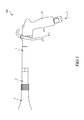
- FIG. 1 is a side view of a revolvingly spraying device according to an embodiment of the present invention
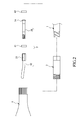
- FIG. 2 is a explosion diagram showing the revolvingly spraying device of FIG. 1
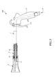
- FIG. 3 is a partial cross-section view of the revolvingly spraying device of FIG. 1
- FIG 4 is a partial enlarged view of the revolvingly spraying device of FIG. 3 .
- a revolvingly spraying device 100 includes a spraying device body 1, a sheath tube 2, and a revolvingly spraying tube 3.
- the spraying device body 1 is used for connecting to a fluid source (not shown) for receiving fluid.
- the spraying device body 1 includes a control handle 11 provided with an adjusting means 111.
- the adjusting means 111 functions as a valve, can be used to adjust the flow rate of a fluid F flowing from the fluid source to the spraying device body 1.
- the sheath tube 2 which is a hollow tube, is provided for allowing inserting the revolvingly spraying tube 3 therethrough.
- One end of the sheath tube 2 is fastened to the spraying device body 1.
- the revolvingly spraying tube 3 includes a transmitting tube 31 and a curved tube 32 connected with the transmitting tube 31.
- the transmitting tube 31 is screwed to the curved tube 32 for conveniently assembling or separaing with each other with rigid fastening structure.
- the transmitting tube 31 is inserted within the sheath tube 2.
- a front bearing 41 is provided at one end, near the curved tube 32, of the transmitting tube 31.
- a rear bearing 42 is provided at the other end thereof.
- the transmitting tube 31 is in fluid communication with the spraying device body 1 in such a manner to transmit the fluid F from the spraying device body 1 through the transmitting tube 31 to the curved tube 32 for spraying.
- the curved tube 32 has an eccentric longitudinal axis, so that the curved tube 32 can be driven by an inclined component force generated by the fluid F passing therethrough. In such a way, the fluid F is sprayed out in every direction after passing through the curved tube 32.
- the front bearing 41 and the rear bearing 42 are holding against an inner periphery surface 20 of the sheath tube 2.
- the front bearing 41 and the rear bearing 42 may be holding against a lateral surface of the sheath tube 2.
- the front bearing 41 and the rear bearing 42 may be holding against other component of the revolvingly spraying device 100, such as the spraying device body 1.
- the sheath tube 2 is provided at the inner periphery surface 20 thereof with a convex portion 21 to space apart between the front bearing 41 and the rear bearing 42, so as to prevent the friction between the front bearing 41 and the rear bearing 42.
- the convex portion 21 has an annular shape which is convenient for manufacture of assembling with the sheath tube 2.
- the convex portion 21 may have a bump shape or the like.
- the sheath tube 2 in this embodiment is further provided at the inner periphery surface 20 thereof with a front fixing member 22 to retain the front side of the front bearing 41. The front bearing 41 is thus positioned fixedly between the convex portion 21 and the front fixing member 22.
- the portion 23 of the sheath tube 2 beyond the outer periphery surface of the front bearing 41 and the outer periphery surface of the rear bearing 42 is solid. That is, the portion 23 is a compact and solid body without any voids therein.
- the solid body of the portion 23 has a stronger structure for strongly supporting the revolvingly spraying tube 3, and for more stably rotating the revolvingly spraying tube 3.
- the revolvingly spraying tube 3 has a front position limiting portion 33 radially protruding therefrom to retain the front side of the front bearing 41 and a rear position limiting portion 34 radially protruding therefrom to retain the rear side of the rear bearing 42. Therefore, it prevents the revolvingly spraying tube 3 deviating away from the sheath tube 2 by means of limiting the axial movement of the revolvingly spraying tube 3, and it also reduce the undesired displacement and vibration by fixing the front bearing 41 and the rear bearing 42.
- the revolvingly spraying tube 3 position limited by a front position limiting portion 33 and a rear position limiting portion 34, is positioned to form a gap with the spraying device body 1 to prevent the friction therebetween, and thus a smooth revolution of the revolvingly spraying tube 3 can be obtained.
- the front position limiting portion 33 and the rear position limiting portion 34 in this embodiment both have an annular shape which is for manufacture as assembling with the revolvingly spraying tube 3.
- the front position limiting portion 33 and the rear position limiting portion 34 may have a bump shape or the like as long as they have function of retaining the front bearing 41 and the rear bearing 42.
- the front position limiting portion 33 is provided at the curved tube 32, and the rear position limiting portion 34 is provided at the transmitting tube 31.
- the front position limiting portion 33 is formed integrately with the curved tube 32
- the rear position limiting portion 34 is formed integrately with the transmitting tube 31. Therefore, the front position limiting portion 33 and the curved tube 32 is manufactured as a single part and the rear position limiting portion 34 and the transmitting tube 31 are manufactured as another single part. Thus, it can reduce the number of components, save time for producing, and prevent the front position limiting portion 33 and the rear position limiting portion 34 deviating away from the transmitting tube 31 and the curved tube 32 respectively.
- the revolvingly spraying device 100 further include a funneled tube 5 provided at the frond side of the sheath tube 2 and surrounding the curved tube 32 of the revolvingly spraying tube 3 to prevent the revolvingly spraying tube 3 from damage.
- the funneled tube 5 also can be used for gathering the fluid F spraying from the revolvingly spraying tube 3 to improve cleaning efficiency.
- FIG. 5 is a partial cross-section view of a revolvingly spraying device according to another embodiment of the present invention.
- the elements of a revolvingly spraying device 100a in this embodiment are similar to those in the embodiment described above.
- the same elements in this embodiment are labeled with the same reference numbers as those in the embodiment described above.
- the revolvingly spraying device 100a in this embodiment further includes an inner tube 6.
- the inner tube 6 is provided with an output end 61 disposed within the revolvingly spraying tube 3 and being extended to an end opening of the curved tube 32 through the transmitting tube 31.
- An input end 62 of the inner tube 6 is provided extending to a water supplying means 12 through the spraying device body 1.
- Venturi effect is induced at the end opening of the curved tube 32 when the fluid F flows through the revolvingly spraying tube 3. This effect makes water contained in the water supplying means 12 being sucked into the inner tube 6 and then outputting from the output end 61 of the inner tube 6. After that, water will be mixed with the fluid F and be sprayed outside through the curved tube 32.
- the revolvingly spraying device of the present invention has industry worth which meets the requirement for a patent.
- the above description should be considered as only the discussion of the preferred embodiments of the present invention.
- a person having ordinary skill in the art may make various modifications to the present invention. Those modifications still fall within the spirit and scope defined by the appended claims.
Landscapes
- Nozzles (AREA)
- Cleaning By Liquid Or Steam (AREA)
- Perforating, Stamping-Out Or Severing By Means Other Than Cutting (AREA)
Applications Claiming Priority (1)
| Application Number | Priority Date | Filing Date | Title |
|---|---|---|---|
| TW101129011A TW201406465A (zh) | 2012-08-10 | 2012-08-10 | 迴旋噴射裝置 |
Publications (2)
| Publication Number | Publication Date |
|---|---|
| EP2695676A1 true EP2695676A1 (de) | 2014-02-12 |
| EP2695676B1 EP2695676B1 (de) | 2017-11-15 |
Family
ID=46880604
Family Applications (1)
| Application Number | Title | Priority Date | Filing Date |
|---|---|---|---|
| EP12183638.1A Active EP2695676B1 (de) | 2012-08-10 | 2012-09-10 | Rotationssprühvorrichtung |
Country Status (6)
| Country | Link |
|---|---|
| US (1) | US9233380B2 (de) |
| EP (1) | EP2695676B1 (de) |
| JP (1) | JP5680046B2 (de) |
| CN (1) | CN103567096B (de) |
| RU (1) | RU2513428C1 (de) |
| TW (1) | TW201406465A (de) |
Cited By (2)
| Publication number | Priority date | Publication date | Assignee | Title |
|---|---|---|---|---|
| GB2537016A (en) * | 2015-02-17 | 2016-10-05 | Neutek Int Inc | Gyrating nozzle spray gun |
| EP3636347A4 (de) * | 2018-04-27 | 2021-05-12 | Bendel Werkzeuge GmbH & Co. KG | Sprühkopfstruktur |
Families Citing this family (7)
| Publication number | Priority date | Publication date | Assignee | Title |
|---|---|---|---|---|
| CN106031904B (zh) * | 2015-03-11 | 2019-04-23 | 乔懋国际股份有限公司 | 回旋喷枪的构造 |
| JP2016203117A (ja) * | 2015-04-24 | 2016-12-08 | 喬懋國際股▲ふん▼有限公司 | 回転式洗浄ガンの構造 |
| JP6588780B2 (ja) * | 2015-09-15 | 2019-10-09 | 株式会社インベント | 噴射ノズル及びこの噴射ノズルを備えた噴射装置 |
| JP2017192880A (ja) * | 2016-04-19 | 2017-10-26 | 株式会社インベント | 噴射ノズル及びこの噴射ノズルを備えた噴射装置 |
| WO2022256183A1 (en) * | 2021-06-01 | 2022-12-08 | Graco Minnesota Inc. | Portable fluid sprayer having a tube dampener |
| CN114017066A (zh) * | 2021-11-04 | 2022-02-08 | 中煤科工集团重庆研究院有限公司 | 一种提高喷浆表面均匀性的方法及自旋转喷枪 |
| CN118925988B (zh) * | 2024-10-12 | 2024-12-20 | 南通协恒设备科技有限公司 | 一种回旋式高压喷枪头及含有其的喷枪 |
Citations (5)
| Publication number | Priority date | Publication date | Assignee | Title |
|---|---|---|---|---|
| EP2255885A1 (de) * | 2009-05-26 | 2010-12-01 | Bendel Werkzeuge Inhaber Frank Bendel | Spritzrohreinheit einer rotierenden Spritzpistole |
| US20100320289A1 (en) * | 2009-03-11 | 2010-12-23 | Chao-Ming Kuo | Structure of spraying device |
| DE202011105869U1 (de) * | 2011-09-16 | 2011-10-24 | 3St Industry Co., Ltd. | Geschwindigkeitsverstellmechanismus für eine Drehsprühpistole |
| US20120056013A1 (en) * | 2009-01-02 | 2012-03-08 | Jeffrey Morris Pedersen | Power Washer Spray Head |
| DE202012101623U1 (de) * | 2011-10-28 | 2012-06-11 | Bendel Werkzeuge Inh. Frank Bendel | Spritzdüsenbaugruppe für pressluftbetriebene Reinigungsgeräte |
Family Cites Families (16)
| Publication number | Priority date | Publication date | Assignee | Title |
|---|---|---|---|---|
| DE1912315B1 (de) * | 1969-03-11 | 1970-10-08 | Kupex Ag | Beregnungsvorrichtung |
| JPS59158454U (ja) * | 1983-04-06 | 1984-10-24 | 株式会社 渡義鉄工所 | 散水機本体 |
| SU1521419A1 (ru) * | 1987-03-18 | 1989-11-15 | Всесоюзный научно-исследовательский институт фитопатологии | Вращающийс распылитель |
| JPH0430060U (de) * | 1990-07-02 | 1992-03-11 | ||
| SU1701224A1 (ru) * | 1990-08-24 | 1991-12-30 | Научно-Производственное Объединение По Сельскохозяйственному Машиностроению "Висхом" | Распылитель жидкости |
| US7568635B2 (en) * | 2004-09-28 | 2009-08-04 | Illinois Tool Works Inc. | Turbo spray nozzle and spray coating device incorporating same |
| US8480011B2 (en) * | 2007-09-04 | 2013-07-09 | Dehn's Innovations, Llc | Nozzle system and method |
| US8056830B1 (en) * | 2009-01-02 | 2011-11-15 | Jeff M Pedersen | Spinner tip shower head |
| TWM369195U (en) * | 2009-01-05 | 2009-11-21 | E Cha E Internat Corp | A kick back spray gun structure |
| CN101940989B (zh) * | 2009-07-07 | 2012-09-05 | 厦门松霖科技有限公司 | 一种水力旋转头部花洒 |
| JP2011020077A (ja) * | 2009-07-17 | 2011-02-03 | Ban Technica:Kk | 洗浄ノズル及びこの洗浄ノズルを備えた洗浄装置 |
| JP5345608B2 (ja) * | 2010-12-22 | 2013-11-20 | プリンス工業株式会社 | 噴水装置 |
| DE202011051202U1 (de) * | 2011-05-11 | 2011-12-16 | Strong Fortress Tool Co., Ltd. | Vorrichtung zum Absprühen von Flüssigkeit |
| TW201244827A (en) * | 2011-05-11 | 2012-11-16 | Strong Fortress Tool Co Ltd | Rotary spraying device |
| TWM418736U (en) * | 2011-09-01 | 2011-12-21 | Strong Fortress Tool Co Ltd | Spray gun apparatus |
| TWM453538U (zh) * | 2012-08-10 | 2013-05-21 | Strong Fortress Tool Co Ltd | 迴旋噴射裝置 |
-
2012
- 2012-08-10 TW TW101129011A patent/TW201406465A/zh unknown
- 2012-09-07 US US13/606,195 patent/US9233380B2/en active Active
- 2012-09-10 EP EP12183638.1A patent/EP2695676B1/de active Active
- 2012-09-13 CN CN201210337616.9A patent/CN103567096B/zh not_active Expired - Fee Related
- 2012-09-27 RU RU2012141269/05A patent/RU2513428C1/ru active
- 2012-11-15 JP JP2012251125A patent/JP5680046B2/ja not_active Expired - Fee Related
Patent Citations (5)
| Publication number | Priority date | Publication date | Assignee | Title |
|---|---|---|---|---|
| US20120056013A1 (en) * | 2009-01-02 | 2012-03-08 | Jeffrey Morris Pedersen | Power Washer Spray Head |
| US20100320289A1 (en) * | 2009-03-11 | 2010-12-23 | Chao-Ming Kuo | Structure of spraying device |
| EP2255885A1 (de) * | 2009-05-26 | 2010-12-01 | Bendel Werkzeuge Inhaber Frank Bendel | Spritzrohreinheit einer rotierenden Spritzpistole |
| DE202011105869U1 (de) * | 2011-09-16 | 2011-10-24 | 3St Industry Co., Ltd. | Geschwindigkeitsverstellmechanismus für eine Drehsprühpistole |
| DE202012101623U1 (de) * | 2011-10-28 | 2012-06-11 | Bendel Werkzeuge Inh. Frank Bendel | Spritzdüsenbaugruppe für pressluftbetriebene Reinigungsgeräte |
Cited By (2)
| Publication number | Priority date | Publication date | Assignee | Title |
|---|---|---|---|---|
| GB2537016A (en) * | 2015-02-17 | 2016-10-05 | Neutek Int Inc | Gyrating nozzle spray gun |
| EP3636347A4 (de) * | 2018-04-27 | 2021-05-12 | Bendel Werkzeuge GmbH & Co. KG | Sprühkopfstruktur |
Also Published As
| Publication number | Publication date |
|---|---|
| CN103567096A (zh) | 2014-02-12 |
| US20140042249A1 (en) | 2014-02-13 |
| CN103567096B (zh) | 2016-08-03 |
| JP5680046B2 (ja) | 2015-03-04 |
| JP2014036948A (ja) | 2014-02-27 |
| TW201406465A (zh) | 2014-02-16 |
| EP2695676B1 (de) | 2017-11-15 |
| RU2012141269A (ru) | 2014-04-10 |
| RU2513428C1 (ru) | 2014-04-20 |
| US9233380B2 (en) | 2016-01-12 |
Similar Documents
| Publication | Publication Date | Title |
|---|---|---|
| EP2695676B1 (de) | Rotationssprühvorrichtung | |
| EP2564935B1 (de) | Spritzpistole | |
| EP2522434B1 (de) | Sprühgerät | |
| EP2255885B1 (de) | Spritzrohreinheit einer rotierenden Spritzpistole | |
| EP1997561A3 (de) | Einteiliges Vakuumsprühpistolengehäuse | |
| EP3284544B1 (de) | Luftkappenanordnung und sprühpistole | |
| EP2522435B1 (de) | Rotierende Sprühvorrichtung | |
| US8267332B1 (en) | Hand held paint sprayer with paint cup and reversible tip | |
| US8807453B2 (en) | Rotary spray nozzle | |
| US9861993B2 (en) | Structure of gyrating nozzle head spray gun | |
| US20190240684A1 (en) | Water spray gun | |
| EP3259077B1 (de) | Adapter für zerstäuber | |
| KR102896579B1 (ko) | 로드와 액상 페인트 흡입 조립체 및 해당 로드의 제조 방법 | |
| EP2243563A3 (de) | Turbulenzsteuerungsanordnung für eine Hochdruckreinigungsmaschine | |
| EP2221110A1 (de) | Rotierende Sprühpistole | |
| US20190000290A1 (en) | Connection Device | |
| US20200055068A1 (en) | Hose adapter for a paint sprayer | |
| CN202951586U (zh) | 回旋喷射装置 | |
| JP7471939B2 (ja) | 背負式噴霧機の噴霧ノズル | |
| CN216078719U (zh) | 一种管连接结构及喷水枪 | |
| US20180117611A1 (en) | Low-pressure and low-noise spray device | |
| CN104028397A (zh) | 一种高压电动喷雾组件 | |
| CN109590122A (zh) | 一种能自由摆动吸管的喷枪 | |
| CN208727774U (zh) | 一种脱硝喷枪 | |
| CN103386379B (zh) | 喷漆枪结构 |
Legal Events
| Date | Code | Title | Description |
|---|---|---|---|
| AK | Designated contracting states |
Kind code of ref document: A1 Designated state(s): AL AT BE BG CH CY CZ DE DK EE ES FI FR GB GR HR HU IE IS IT LI LT LU LV MC MK MT NL NO PL PT RO RS SE SI SK SM TR |
|
| AX | Request for extension of the european patent |
Extension state: BA ME |
|
| PUAI | Public reference made under article 153(3) epc to a published international application that has entered the european phase |
Free format text: ORIGINAL CODE: 0009012 |
|
| 17P | Request for examination filed |
Effective date: 20140804 |
|
| RBV | Designated contracting states (corrected) |
Designated state(s): AL AT BE BG CH CY CZ DE DK EE ES FI FR GB GR HR HU IE IS IT LI LT LU LV MC MK MT NL NO PL PT RO RS SE SI SK SM TR |
|
| GRAP | Despatch of communication of intention to grant a patent |
Free format text: ORIGINAL CODE: EPIDOSNIGR1 |
|
| INTG | Intention to grant announced |
Effective date: 20170612 |
|
| GRAS | Grant fee paid |
Free format text: ORIGINAL CODE: EPIDOSNIGR3 |
|
| GRAA | (expected) grant |
Free format text: ORIGINAL CODE: 0009210 |
|
| AK | Designated contracting states |
Kind code of ref document: B1 Designated state(s): AL AT BE BG CH CY CZ DE DK EE ES FI FR GB GR HR HU IE IS IT LI LT LU LV MC MK MT NL NO PL PT RO RS SE SI SK SM TR |
|
| REG | Reference to a national code |
Ref country code: CH Ref legal event code: EP Ref country code: GB Ref legal event code: FG4D Ref country code: AT Ref legal event code: REF Ref document number: 945740 Country of ref document: AT Kind code of ref document: T Effective date: 20171115 |
|
| REG | Reference to a national code |
Ref country code: IE Ref legal event code: FG4D |
|
| REG | Reference to a national code |
Ref country code: DE Ref legal event code: R096 Ref document number: 602012039721 Country of ref document: DE |
|
| REG | Reference to a national code |
Ref country code: NL Ref legal event code: MP Effective date: 20171115 |
|
| REG | Reference to a national code |
Ref country code: LT Ref legal event code: MG4D |
|
| REG | Reference to a national code |
Ref country code: AT Ref legal event code: MK05 Ref document number: 945740 Country of ref document: AT Kind code of ref document: T Effective date: 20171115 |
|
| PG25 | Lapsed in a contracting state [announced via postgrant information from national office to epo] |
Ref country code: SE Free format text: LAPSE BECAUSE OF FAILURE TO SUBMIT A TRANSLATION OF THE DESCRIPTION OR TO PAY THE FEE WITHIN THE PRESCRIBED TIME-LIMIT Effective date: 20171115 Ref country code: FI Free format text: LAPSE BECAUSE OF FAILURE TO SUBMIT A TRANSLATION OF THE DESCRIPTION OR TO PAY THE FEE WITHIN THE PRESCRIBED TIME-LIMIT Effective date: 20171115 Ref country code: NO Free format text: LAPSE BECAUSE OF FAILURE TO SUBMIT A TRANSLATION OF THE DESCRIPTION OR TO PAY THE FEE WITHIN THE PRESCRIBED TIME-LIMIT Effective date: 20180215 Ref country code: LT Free format text: LAPSE BECAUSE OF FAILURE TO SUBMIT A TRANSLATION OF THE DESCRIPTION OR TO PAY THE FEE WITHIN THE PRESCRIBED TIME-LIMIT Effective date: 20171115 Ref country code: NL Free format text: LAPSE BECAUSE OF FAILURE TO SUBMIT A TRANSLATION OF THE DESCRIPTION OR TO PAY THE FEE WITHIN THE PRESCRIBED TIME-LIMIT Effective date: 20171115 Ref country code: ES Free format text: LAPSE BECAUSE OF FAILURE TO SUBMIT A TRANSLATION OF THE DESCRIPTION OR TO PAY THE FEE WITHIN THE PRESCRIBED TIME-LIMIT Effective date: 20171115 |
|
| PG25 | Lapsed in a contracting state [announced via postgrant information from national office to epo] |
Ref country code: BG Free format text: LAPSE BECAUSE OF FAILURE TO SUBMIT A TRANSLATION OF THE DESCRIPTION OR TO PAY THE FEE WITHIN THE PRESCRIBED TIME-LIMIT Effective date: 20180215 Ref country code: GR Free format text: LAPSE BECAUSE OF FAILURE TO SUBMIT A TRANSLATION OF THE DESCRIPTION OR TO PAY THE FEE WITHIN THE PRESCRIBED TIME-LIMIT Effective date: 20180216 Ref country code: LV Free format text: LAPSE BECAUSE OF FAILURE TO SUBMIT A TRANSLATION OF THE DESCRIPTION OR TO PAY THE FEE WITHIN THE PRESCRIBED TIME-LIMIT Effective date: 20171115 Ref country code: HR Free format text: LAPSE BECAUSE OF FAILURE TO SUBMIT A TRANSLATION OF THE DESCRIPTION OR TO PAY THE FEE WITHIN THE PRESCRIBED TIME-LIMIT Effective date: 20171115 Ref country code: RS Free format text: LAPSE BECAUSE OF FAILURE TO SUBMIT A TRANSLATION OF THE DESCRIPTION OR TO PAY THE FEE WITHIN THE PRESCRIBED TIME-LIMIT Effective date: 20171115 Ref country code: AT Free format text: LAPSE BECAUSE OF FAILURE TO SUBMIT A TRANSLATION OF THE DESCRIPTION OR TO PAY THE FEE WITHIN THE PRESCRIBED TIME-LIMIT Effective date: 20171115 |
|
| PG25 | Lapsed in a contracting state [announced via postgrant information from national office to epo] |
Ref country code: SK Free format text: LAPSE BECAUSE OF FAILURE TO SUBMIT A TRANSLATION OF THE DESCRIPTION OR TO PAY THE FEE WITHIN THE PRESCRIBED TIME-LIMIT Effective date: 20171115 Ref country code: DK Free format text: LAPSE BECAUSE OF FAILURE TO SUBMIT A TRANSLATION OF THE DESCRIPTION OR TO PAY THE FEE WITHIN THE PRESCRIBED TIME-LIMIT Effective date: 20171115 Ref country code: CY Free format text: LAPSE BECAUSE OF FAILURE TO SUBMIT A TRANSLATION OF THE DESCRIPTION OR TO PAY THE FEE WITHIN THE PRESCRIBED TIME-LIMIT Effective date: 20171115 Ref country code: EE Free format text: LAPSE BECAUSE OF FAILURE TO SUBMIT A TRANSLATION OF THE DESCRIPTION OR TO PAY THE FEE WITHIN THE PRESCRIBED TIME-LIMIT Effective date: 20171115 Ref country code: CZ Free format text: LAPSE BECAUSE OF FAILURE TO SUBMIT A TRANSLATION OF THE DESCRIPTION OR TO PAY THE FEE WITHIN THE PRESCRIBED TIME-LIMIT Effective date: 20171115 |
|
| REG | Reference to a national code |
Ref country code: DE Ref legal event code: R097 Ref document number: 602012039721 Country of ref document: DE |
|
| PG25 | Lapsed in a contracting state [announced via postgrant information from national office to epo] |
Ref country code: SM Free format text: LAPSE BECAUSE OF FAILURE TO SUBMIT A TRANSLATION OF THE DESCRIPTION OR TO PAY THE FEE WITHIN THE PRESCRIBED TIME-LIMIT Effective date: 20171115 Ref country code: PL Free format text: LAPSE BECAUSE OF FAILURE TO SUBMIT A TRANSLATION OF THE DESCRIPTION OR TO PAY THE FEE WITHIN THE PRESCRIBED TIME-LIMIT Effective date: 20171115 Ref country code: RO Free format text: LAPSE BECAUSE OF FAILURE TO SUBMIT A TRANSLATION OF THE DESCRIPTION OR TO PAY THE FEE WITHIN THE PRESCRIBED TIME-LIMIT Effective date: 20171115 |
|
| PLBE | No opposition filed within time limit |
Free format text: ORIGINAL CODE: 0009261 |
|
| STAA | Information on the status of an ep patent application or granted ep patent |
Free format text: STATUS: NO OPPOSITION FILED WITHIN TIME LIMIT |
|
| REG | Reference to a national code |
Ref country code: FR Ref legal event code: PLFP Year of fee payment: 7 |
|
| 26N | No opposition filed |
Effective date: 20180817 |
|
| PG25 | Lapsed in a contracting state [announced via postgrant information from national office to epo] |
Ref country code: SI Free format text: LAPSE BECAUSE OF FAILURE TO SUBMIT A TRANSLATION OF THE DESCRIPTION OR TO PAY THE FEE WITHIN THE PRESCRIBED TIME-LIMIT Effective date: 20171115 |
|
| PG25 | Lapsed in a contracting state [announced via postgrant information from national office to epo] |
Ref country code: MC Free format text: LAPSE BECAUSE OF FAILURE TO SUBMIT A TRANSLATION OF THE DESCRIPTION OR TO PAY THE FEE WITHIN THE PRESCRIBED TIME-LIMIT Effective date: 20171115 |
|
| REG | Reference to a national code |
Ref country code: CH Ref legal event code: PL |
|
| REG | Reference to a national code |
Ref country code: BE Ref legal event code: MM Effective date: 20180930 |
|
| REG | Reference to a national code |
Ref country code: IE Ref legal event code: MM4A |
|
| PG25 | Lapsed in a contracting state [announced via postgrant information from national office to epo] |
Ref country code: LU Free format text: LAPSE BECAUSE OF NON-PAYMENT OF DUE FEES Effective date: 20180910 |
|
| PG25 | Lapsed in a contracting state [announced via postgrant information from national office to epo] |
Ref country code: IE Free format text: LAPSE BECAUSE OF NON-PAYMENT OF DUE FEES Effective date: 20180910 |
|
| PG25 | Lapsed in a contracting state [announced via postgrant information from national office to epo] |
Ref country code: LI Free format text: LAPSE BECAUSE OF NON-PAYMENT OF DUE FEES Effective date: 20180930 Ref country code: BE Free format text: LAPSE BECAUSE OF NON-PAYMENT OF DUE FEES Effective date: 20180930 Ref country code: CH Free format text: LAPSE BECAUSE OF NON-PAYMENT OF DUE FEES Effective date: 20180930 |
|
| PG25 | Lapsed in a contracting state [announced via postgrant information from national office to epo] |
Ref country code: MT Free format text: LAPSE BECAUSE OF NON-PAYMENT OF DUE FEES Effective date: 20180910 |
|
| PG25 | Lapsed in a contracting state [announced via postgrant information from national office to epo] |
Ref country code: TR Free format text: LAPSE BECAUSE OF FAILURE TO SUBMIT A TRANSLATION OF THE DESCRIPTION OR TO PAY THE FEE WITHIN THE PRESCRIBED TIME-LIMIT Effective date: 20171115 |
|
| PGFP | Annual fee paid to national office [announced via postgrant information from national office to epo] |
Ref country code: GB Payment date: 20191023 Year of fee payment: 8 |
|
| PG25 | Lapsed in a contracting state [announced via postgrant information from national office to epo] |
Ref country code: HU Free format text: LAPSE BECAUSE OF FAILURE TO SUBMIT A TRANSLATION OF THE DESCRIPTION OR TO PAY THE FEE WITHIN THE PRESCRIBED TIME-LIMIT; INVALID AB INITIO Effective date: 20120910 Ref country code: PT Free format text: LAPSE BECAUSE OF FAILURE TO SUBMIT A TRANSLATION OF THE DESCRIPTION OR TO PAY THE FEE WITHIN THE PRESCRIBED TIME-LIMIT Effective date: 20171115 |
|
| PG25 | Lapsed in a contracting state [announced via postgrant information from national office to epo] |
Ref country code: MK Free format text: LAPSE BECAUSE OF NON-PAYMENT OF DUE FEES Effective date: 20171115 |
|
| PG25 | Lapsed in a contracting state [announced via postgrant information from national office to epo] |
Ref country code: AL Free format text: LAPSE BECAUSE OF FAILURE TO SUBMIT A TRANSLATION OF THE DESCRIPTION OR TO PAY THE FEE WITHIN THE PRESCRIBED TIME-LIMIT Effective date: 20171115 Ref country code: IS Free format text: LAPSE BECAUSE OF FAILURE TO SUBMIT A TRANSLATION OF THE DESCRIPTION OR TO PAY THE FEE WITHIN THE PRESCRIBED TIME-LIMIT Effective date: 20180315 |
|
| GBPC | Gb: european patent ceased through non-payment of renewal fee |
Effective date: 20200910 |
|
| PG25 | Lapsed in a contracting state [announced via postgrant information from national office to epo] |
Ref country code: GB Free format text: LAPSE BECAUSE OF NON-PAYMENT OF DUE FEES Effective date: 20200910 |
|
| PGFP | Annual fee paid to national office [announced via postgrant information from national office to epo] |
Ref country code: DE Payment date: 20250902 Year of fee payment: 14 |
|
| PGFP | Annual fee paid to national office [announced via postgrant information from national office to epo] |
Ref country code: IT Payment date: 20250922 Year of fee payment: 14 |
|
| PGFP | Annual fee paid to national office [announced via postgrant information from national office to epo] |
Ref country code: FR Payment date: 20250908 Year of fee payment: 14 |