EP2696010B1 - Unterwasserhebebühne für ein Schwimmbad - Google Patents
Unterwasserhebebühne für ein Schwimmbad Download PDFInfo
- Publication number
- EP2696010B1 EP2696010B1 EP13306102.8A EP13306102A EP2696010B1 EP 2696010 B1 EP2696010 B1 EP 2696010B1 EP 13306102 A EP13306102 A EP 13306102A EP 2696010 B1 EP2696010 B1 EP 2696010B1
- Authority
- EP
- European Patent Office
- Prior art keywords
- sliding sleeve
- pool
- disposed
- water
- sealing
- Prior art date
- Legal status (The legal status is an assumption and is not a legal conclusion. Google has not performed a legal analysis and makes no representation as to the accuracy of the status listed.)
- Not-in-force
Links
Images


Classifications
-
- A—HUMAN NECESSITIES
- A63—SPORTS; GAMES; AMUSEMENTS
- A63J—DEVICES FOR THEATRES, CIRCUSES, OR THE LIKE; CONJURING APPLIANCES OR THE LIKE
- A63J1/00—Stage arrangements
-
- E—FIXED CONSTRUCTIONS
- E04—BUILDING
- E04H—BUILDINGS OR LIKE STRUCTURES FOR PARTICULAR PURPOSES; SWIMMING OR SPLASH BATHS OR POOLS; MASTS; FENCING; TENTS OR CANOPIES, IN GENERAL
- E04H4/00—Swimming or splash baths or pools
- E04H4/06—Safety devices; Coverings for baths
- E04H4/065—Floors adjustable in height
-
- E—FIXED CONSTRUCTIONS
- E04—BUILDING
- E04H—BUILDINGS OR LIKE STRUCTURES FOR PARTICULAR PURPOSES; SWIMMING OR SPLASH BATHS OR POOLS; MASTS; FENCING; TENTS OR CANOPIES, IN GENERAL
- E04H3/00—Buildings or groups of buildings for public or similar purposes; Institutions, e.g. infirmaries or prisons
- E04H3/10—Buildings or groups of buildings for public or similar purposes; Institutions, e.g. infirmaries or prisons for meetings, entertainments, or sports
- E04H3/22—Theatres; Concert halls; Studios for broadcasting, cinematography, television or similar purposes
-
- E—FIXED CONSTRUCTIONS
- E04—BUILDING
- E04H—BUILDINGS OR LIKE STRUCTURES FOR PARTICULAR PURPOSES; SWIMMING OR SPLASH BATHS OR POOLS; MASTS; FENCING; TENTS OR CANOPIES, IN GENERAL
- E04H3/00—Buildings or groups of buildings for public or similar purposes; Institutions, e.g. infirmaries or prisons
- E04H3/10—Buildings or groups of buildings for public or similar purposes; Institutions, e.g. infirmaries or prisons for meetings, entertainments, or sports
- E04H3/22—Theatres; Concert halls; Studios for broadcasting, cinematography, television or similar purposes
- E04H3/24—Constructional features of stages
Definitions
- the present invention relates to a lifting platform, and particularly relates to an underwater lifting platform for water show.
- Modern shows require coordination of scenes and shows, as well as fast changes and movement of the cues and scenes.
- an underwater lifting platform moves underwater props into the vision of the audiences, or the underwater lifting platform rises above the water according to requirement of the show, in order to provide a show stage above the water for the performers.
- the main problem of this swimming bath is that it needs a complicated architecture and a complicated drive mechanism in order to lift the false bottom.
- the present invention provides an underwater lifting platform for water show, which may mitigate and avoid the above mentioned problems.
- the present invention provides an underwater lifting platform for a water show, which may mitigate and avoid the above mentioned problems.
- the present invention provides an underwater lifting platform for water show according to claim 1.
- the drive and transmission components are prevented from water, thereby water pollution due to the leakage of hydraulic oil into the water and the potential safety risks of water being charged due to electric leakage when using electricity in water are eliminated. Further, in the underwater lifting platform for water show as provided by the present invention, power is transmitted between the dry foundation pit and water zone of the pool through the lifting rod with a simple structure, thereby the problems of leakage of lubricating medium and rust protection of materials when the transmission mechanism is disposed in water are avoided.
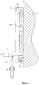
- FIG. 1 is a schematic view showing the structure of the underwater lifting platform for water show, according to an embodiment of the present invention.
- the present invention provides an underwater lifting platform for water show, the lifting platform is disposed in a pool, the pool comprises a water zone 2 above the bottom 1 of the pool for water storage and a foundation pit 3 below the bottom 1 of the pool for accessing by a personnel for maintenance and apparatus installation, and the lifting platform comprises a power mechanism 4 disposed in the foundation pit, a stage mechanism 5 disposed in the water zone and a lifting rod 6 connecting the drive mechanism 4 with the platform structure 5 through the bottom of the pool;
- the platform structure 5 comprises a stage body 51, a supporting frame 52 connected to the stage body 51 and a guiding device 53 connected with the supporting frame 52 and the bottom 1 of the pool respectively;
- the drive mechanism 4 comprises a guiding steel rack 41 fixed on the bottom of the foundation pit 3, a guiding frame 42 which is connected with the guiding steel rack 41 and can move upwards and downwards along the guiding steel rack 41, and a driving motor 43 connected with the guiding frame 42;
- the bottom 1 of the pool is provided with a hollow through-hole, the through-hole is provided with a sliding sleeve, and the lifting rod 6 is connected with the supporting frame 52 and the guiding frame 42 respectively through the sliding sleeve.
- the lifting rod 6 can be stainless steel tube and power is transmitted between the dry foundation pit 3 and water zone 2 of the pool through the stainless steel tube lifting rod with a simple structure, thereby the problems of leakage of lubricating medium and rust protection of materials when the transmission mechanism is disposed in water are avoided.
- the stage body 51 When performing a show, the stage body 51 rises above the water to carry performers and props.
- the supporting frame 52 provides structural strength support for the stage body 51.
- the supporting frame 52 and the stage body 51 may be lowered to the bottom 1 of the pool by lowering the lifting rod 6, thereby space occupation of the water zone 2 is decreased, without affecting applications of the pool as swimming pool or diving pool.
- the guiding device 53 may be one or more groups of foldable metal frames, for ensuring that there is no lateral displacement of the supporting frame 52 and the stage body 51 during lifting and use.
- the guiding frame 42 may be moved upwards and downwards along the guiding steel rack 41, thereby the lifting rod 6 is capable of bringing the supporting frame 52 and the stage body 51 up and down.
- the driving motor 43 may be installed at a site chosen flexibly, and may be fixed at the bottom of the foundation pit, or may be fixed on the guiding steel rack 41.
- the driving motor 43 may be connected to the guiding frame 42 through components such as a brake, a commutation reducer, driving shaft and so on, to drive the guiding frame 42.
- the guiding steel rack 41 may be further provided with a counterweight device connected with the guiding frame 42, such that driving requirement of the guiding frame 42 may be fulfilled with a driving motor 43 having relatively low power.
- Figure 2 is a partially enlarged schematic sectional view of zone A of the lifting platform shown in Figure 1 ;
- Figure 3 is a partially enlarged schematic sectional view of the first sliding sleeve of the lifting platform shown in Figure 2 ;
- Figure 4 is a partially enlarged schematic sectional view of the second sliding sleeve of the lifting platform shown in Figure 2 .
- the sliding sleeve comprises a first sliding sleeve 7 disposed in the water zone and a second sliding sleeve 8 disposed in the foundation pit, the first sliding sleeve 7 is connected to an upper surface of the bottom 1 of the pool with a first sealing assembly 9, and the second sliding sleeve 8 is connected to an lower surface of the bottom 1 of the pool with a second sealing assembly 10;
- the first sealing assembly 9 comprises a first base 91, a first supporting member 92 and a first positioning member 93 sequentially connected by bolts, and the first base 91 is fixedly connected to the upper surface of the bottom 1 of the pool by bolts;
- the first sliding sleeve 7 comprises a first sliding sleeve cover 71, a first stopper member 72, a first sealing gasket 73 sequentially connected by bolts, the first sliding sleeve cover 71 is fixedly connected with the first positioning member 93 by bolts, and a first sealing member 74 is disposed between the first sliding sleeve cover 71 and the lifting rod 6;
- the second sealing assembly 10 comprises a second base 101, a second supporting member 102 and a second positioning member 103 sequentially connected by bolts, and the second base 101 is fixedly connected with a lower surface of the bottom 1 of the pool by bolts; the second sealing assembly 10 further comprises a position adjusting member 104, and the second position adjusting member 104 is connected through clamping by the second positioning member 103 and the second supporting member 102;
- the second sliding sleeve 8 comprises a second sliding sleeve cover 81, a second stopper member 82 sequentially connected by bolts, the second sliding sleeve cover 81 is fixedly connected with the position adjusting member 104 by bolts, and a second sealing member 83 is disposed between the second sliding sleeve cover 81 and the lifting rod 6.
- the sliding sleeve comprises a first sliding sleeve 7 disposed in the water zone and a second sliding sleeve 8 disposed in the foundation pit, the first sliding sleeve 7 is connected to the upper surface of the bottom 1 of the pool through a first sealing assembly 9, and the second sliding sleeve 8 is connected to the lower surface of the bottom 1 of the pool through a second sealing assembly 10; as such, when maintaining the lifting platform, the respective sliding sleeve or sealing assembly may be replaced without draining of water inside the pool, which greatly saves the cost of repair and maintenance.
- the inner diameter of the first base 91 and the second base 101 is the same as the diameter of the through-hole of the bottom 1 of the pool.
- the first base 91 and the second base 101 may fixedly connected with the bottom 1 of the pool by bolts distributed uniformly around the circumference.
- the first supporting member 92 and the second supporting member 102 are used to adjust the installation position of the respective sliding sleeves, such that the respective sliding sleeves are at convenient position for handling when performing assembling operations.
- the lifting rod 6 and corresponding sliding sleeves with different diameters may be installed at the bottom 1 of the pool.
- the first sliding sleeve cover 71 and the second sliding sleeve cover 81 press the first sealing member 74 and the second sealing member 83 against the lifting rod 6, such that water in the water zone 2 would not leak to the foundation pit 3 during rise and fall of the lifting rod 6.
- the first stopper member 72 and the second stopper member 82 coordinate with the first sliding sleeve cover 71 and the second sliding sleeve cover 81 respectively to limit the stroke of the first sealing member 74 and the second sealing member 83, so as to avoid a situation that the first sliding sleeve cover 71 and the second sliding sleeve cover 81 deviate from their operation position and cause leakage of water from water zone 2 to the foundation pit 3.
- the first sealing gasket 73 is disposed above the first stopper member 72. Under the gravity of water, the first sealing gasket 73 is more capable of preventing water of the water zone 2 from leaking to the junction of the first sliding sleeve 7 and the lifting rod 6.
- the second sealing assembly 10 further comprises a position adjusting member 104, and the position adjusting member 104 is connected through clamping by the second positioning member 103 and the second supporting member 102; when maintaining the lifting platform, the position of the position adjusting member 104 may be adjusted flexibly by adjusting the position of the second positioning member 103, so that the perpendicularity of the lifting rod 6 may be adjusted.
- a sleeve 61 is disposed between the first sealing assembly 9 and the second sealing assembly 10 and sleeved at the outer side of the lifting rod 6, the first sliding sleeve cover 71 and the second sliding sleeve cover 81.
- the sleeve 61 may be a bellows made of metal or plastic.
- the sleeve 61 may collect the leaked water and drain it through the junction of the second sliding sleeve 8 and the lifting rod 6, so as to avoid infiltration and permeation of water into the respective junctions of the second sealing assembly 10.
- the second sliding sleeve cover 81 is provided with a water diverting port 811 for diverting water, which leads to a position underneath the second sealing member 83.
- a water diverting port 811 for diverting water, which leads to a position underneath the second sealing member 83.
- a water diverting connector 84 may be installed at the water diverting port 811, such that the leaked water may be collected through a pipe and diverted to a sump pit for water storage that is away from the drive mechanism 4 in the foundation pit 3, so as to avoid the potential safety risks such as electric leakage and corrosion of the drive mechanism 4, caused by water.
- a positioning block 105 is disposed on the second base 101, and a positioning bolt 106 is disposed on the positioning block 105 for pressing against the second positioning member 103. Since the position adjusting member 104 is connected through clamping by the second positioning member 103 and the second supporting member 102, it is convenient to adjust the position of the second positioning member 103 through the positioning bolt 106, and further to adjust the position of the position adjusting member 104, so as to adjust the perpendicularity of the lifting rod 6.
- At least two sealing rings 62 are disposed between the first sliding sleeve cover 71 and the lifting rod 6, at least one sealing ring 62 is disposed between the first stopper member 72 and the lifting rod 6, and at least two sealing rings 62 are disposed between the second sliding sleeve cover 81 and the lifting rod 6.
- the drive and transmission components are prevented from water, thereby water pollution due to the leakage of hydraulic oil into the water and the potential safety risks of water being charged due to electric leakage when using electricity in water are eliminated. Further, in the underwater lifting platform for water show as provided by the present invention, power is transmitted between the dry foundation pit and water zone of the pool through the lifting rod with a simple structure, thereby the problems of leakage of lubricating medium and rust protection of materials in the event that the transmission mechanism is disposed in water are avoided.
Landscapes
- Engineering & Computer Science (AREA)
- Architecture (AREA)
- Civil Engineering (AREA)
- Structural Engineering (AREA)
- Multimedia (AREA)
- Buildings Adapted To Withstand Abnormal External Influences (AREA)
- Barrages (AREA)
- Other Liquid Machine Or Engine Such As Wave Power Use (AREA)
- Revetment (AREA)
- Earth Drilling (AREA)
- Catching Or Destruction (AREA)
- Hydraulic Turbines (AREA)
- Types And Forms Of Lifts (AREA)
- Load-Engaging Elements For Cranes (AREA)
Claims (6)
- Unterwasserhebebühne für Wasservorführungen, bei der die Hebebühne in einem Becken angeordnet ist, wobei: das Becken eine Wasserzone (2) über dem Beckenboden (1) für die Speicherung des Wassers und eine Fundamentgrube (3) für den Zugang des Personals im Rahmen von Wartung und Installation der Geräte umfasst, und die Hebebühne einen in der Fundamentgrube (3) angeordneten Antriebsmechanismus (4), einen in der Wasserzone (2) angeordneten Bühnenmechanismus (5) sowie eine Hubstange (6) umfasst, die den Antriebsmechanismus (4) mit dem Bühnenmechanismus (5) verbindet;
dadurch gekennzeichnet, dass sich die Fundamentgrube (3) unter dem Beckenboden befindet, und dass die Hubstange (6) durch den Beckenboden (1) geführt wird,
und dass die Plattformkonstruktion einen Plattformkörper (51), einen mit dem Plattformkörper (51) verbundenen Tragrahmen (52) und eine Führungsvorrichtung (53) umfasst, die mit dem Tragrahmen (52) beziehungsweise mit dem Beckenboden (1) verbunden ist;
und dass der Antriebsmechanismus (4) ein am Boden der Fundamentgrube (3) befestigtes Stahlgestell (41) zur Führung, einen mit dem Stahlgestell (41) zur Führung verbundenen Führungsrahmen (42), der entlang diesem Stahlgestell (41) zur Führung nach oben und unten bewegt werden kann, sowie einen Antriebsmotor (43) umfasst, der mit dem Führungsrahmen (42) verbunden ist;
und dadurch gekennzeichnet, dass der Beckenboden (1) mit einer hohlen Durchgangsbohrung versehen ist, wobei die Durchgangsbohrung mit einer Gleitbuchse versehen ist und die durch diese Gleitbuchse geführte Hubstange (6) mit dem Tragrahmen (52) beziehungsweise mit dem Führungsrahmen (42) verbunden ist. - Hebebühne nach Anspruch 1, bei der die Gleitbuchse eine erste Gleitbuchse (7) umfasst, die in der Wasserzone angeordnet ist, und eine zweite Gleitbuchse (8), die in der Fundamentgrube angeordnet ist, wobei die erste Gleitbuchse (7) über eine erste Dichtungsanordnung (9) mit der oberen Fläche des Beckenbodens (1) und die zweite Gleitbuchse (8) über eine zweite Dichtungsanordnung (10) mit der unteren Fläche des Beckenbodens (1) verbunden ist;
die erste Dichtungsanordnung (9) umfasst einen ersten Sockel (91), ein erstes Stützglied (92) und ein erstes Positionierglied (93), die nacheinander mit Bolzen verbunden werden, wobei der erste Sockel (91) über Bolzen starr mit der oberen Fläche des Beckenbodens (1) verbunden ist;
die erste Gleitbuchse (7) umfasst eine erste Gleitbuchsenabdeckung (71), ein erstes Stopperglied (72) und eine erste Dichtung (73), die nacheinander mit Bolzen verbunden werden, wobei die erste Gleitbuchsenabdeckung (71) über Bolzen starr mit dem ersten Positionierglied (93) verbunden ist und zwischen der ersten Gleitbuchsenabdeckung (71) und der Hubstange (6) ein erstes Dichtungsglied (74) angeordnet ist;
die zweite Dichtungsanordnung (10) umfasst einen zweiten Sockel (101), ein zweites Stützglied (102) und ein zweites Positionierglied (103), die nacheinander mit Bolzen verbunden werden, wobei der zweite Sockel (101) über Bolzen starr mit der unteren Fläche des Beckenbodens (1) verbunden ist; die zweite Dichtungsanordnung (10) umfasst ferner ein Justierglied (104) für die Positionierung, wobei das zweite Justierglied (104) für die Positionierung durch Klemmung zwischen dem zweiten Positionierglied (103) und dem zweiten Stützglied (102) gehalten wird;
die zweite Gleitbuchse (8) umfasst eine zweite Gleitbuchsenabdeckung (81) und ein zweites Stopperglied (82), die nacheinander mit Bolzen verbunden werden, wobei die zweite Gleitbuchsenabdeckung (81) über Bolzen starr mit dem ersten Justierglied (104) für die Positionierung verbunden ist und zwischen der zweiten Gleitbuchsenabdeckung (81) und der Hubstange (6) ein zweites Dichtungsglied (83) angeordnet ist. - Hebebühne nach Anspruch 2, bei der zwischen der ersten Dichtungsanordnung (9) und der zweiten Dichtungsanordnung (10) eine Muffe (61) angeordnet ist, die an der der Hubstange (6) abgewandten Seite die erste Gleitbuchsenabdeckung (71) und die zweite Gleitbuchsenabdeckung (81) einfasst.
- Hebebühne nach Anspruch 2, bei der die zweite Gleitbuchsenabdeckung (81) mit einer Wasserableitöffnung (811) zur Ableitung von Wasser versehen ist, die zu einem Wasserauslass unter dem zweiten Dichtungsglied (83) führt.
- Hebebühne nach Anspruch 2, bei der am zweiten Sockel (101) ein Positionierblock (105) angeordnet ist, an dem (105) ein Positionierbolzen (106) angebracht ist, der Druck auf das zweite Positionierglied (103) ausübt.
- Hebebühne nach Anspruch 2, bei der zwischen der ersten Gleitbuchsenabdeckung (71) und der Hubstange (6) mindestens zwei Dichtungsringe (62) angeordnet sind, zwischen dem ersten Stopperglied (72) und der Hubstange (6) mindestens ein Dichtungsring (62) angeordnet ist und zwischen der zweiten Gleitbuchsenabdeckung (81) und der Hubstange (6) mindestens zwei Dichtungsringe (62) angeordnet sind.
Applications Claiming Priority (1)
| Application Number | Priority Date | Filing Date | Title |
|---|---|---|---|
| CN201210283544.4A CN103572987B (zh) | 2012-08-10 | 2012-08-10 | 用于水中表演的升降台 |
Publications (3)
| Publication Number | Publication Date |
|---|---|
| EP2696010A2 EP2696010A2 (de) | 2014-02-12 |
| EP2696010A3 EP2696010A3 (de) | 2014-09-03 |
| EP2696010B1 true EP2696010B1 (de) | 2016-03-30 |
Family
ID=48986072
Family Applications (1)
| Application Number | Title | Priority Date | Filing Date |
|---|---|---|---|
| EP13306102.8A Not-in-force EP2696010B1 (de) | 2012-08-10 | 2013-07-30 | Unterwasserhebebühne für ein Schwimmbad |
Country Status (15)
| Country | Link |
|---|---|
| EP (1) | EP2696010B1 (de) |
| JP (1) | JP5723424B2 (de) |
| KR (1) | KR101521705B1 (de) |
| CN (1) | CN103572987B (de) |
| AR (1) | AR093826A1 (de) |
| BR (1) | BR102013020484A2 (de) |
| CA (1) | CA2820418C (de) |
| CL (1) | CL2013002328A1 (de) |
| CO (1) | CO7180047A1 (de) |
| ES (1) | ES2575019T3 (de) |
| MY (1) | MY167062A (de) |
| PE (1) | PE20141725A1 (de) |
| RU (1) | RU2545229C2 (de) |
| SG (1) | SG2013047899A (de) |
| UY (1) | UY34970A (de) |
Families Citing this family (24)
| Publication number | Priority date | Publication date | Assignee | Title |
|---|---|---|---|---|
| GB2507496B (en) * | 2012-10-30 | 2016-12-07 | Variopool B V | Swimming pool with adjustable pool floor system |
| CN105041007B (zh) * | 2015-02-10 | 2018-02-09 | 万达文化旅游规划研究院有限公司 | 闭环控制的双驱动浮筒式水中升降舞台 |
| CN106223654A (zh) * | 2016-07-26 | 2016-12-14 | 安徽饰界广告有限公司 | 一种多功能舞台 |
| CN106223656A (zh) * | 2016-07-26 | 2016-12-14 | 安徽饰界广告有限公司 | 一种多功能舞台 |
| CN106088687A (zh) * | 2016-07-26 | 2016-11-09 | 安徽饰界广告有限公司 | 一种多功能舞台 |
| CN106223658B (zh) * | 2016-07-29 | 2018-12-21 | 宣月罗 | 一种表演用舞台结构 |
| CN106223655B (zh) * | 2016-07-29 | 2018-12-25 | 宣月罗 | 一种布景可移动的舞台 |
| CN106592616A (zh) * | 2016-11-03 | 2017-04-26 | 东莞市联洲知识产权运营管理有限公司 | 一种蓄水式房屋地基构造 |
| CN106567401B (zh) * | 2016-11-03 | 2018-12-04 | 绍兴柯桥富荣纺织有限公司 | 一种升降式地基构造 |
| CN106773461B (zh) * | 2016-12-02 | 2017-12-12 | 温嘉昊 | 多场景摄像布景系统 |
| CN107244639A (zh) * | 2017-07-20 | 2017-10-13 | 兰州理工大学 | 舞台涉水旋转升降组合装备 |
| CN107654072A (zh) * | 2017-08-25 | 2018-02-02 | 上海建工二建集团有限公司 | 一种钢平台及其施工方法 |
| CN108126358A (zh) * | 2017-12-08 | 2018-06-08 | 方特欢乐世界(芜湖)经营管理有限公司 | 一种娱乐升降道具台 |
| CN108086724B (zh) * | 2017-12-18 | 2023-12-22 | 华强方特(芜湖)文化产业有限公司 | 一种双舞台人员输送装置 |
| CN108487698A (zh) * | 2018-03-29 | 2018-09-04 | 苏州乐天企渊文化创意有限公司 | 一种可升降的旋转舞台 |
| CN109138533A (zh) * | 2018-10-09 | 2019-01-04 | 林凤娟 | 一种集合式表演舞台专用升降台 |
| CN109838123B (zh) * | 2019-03-28 | 2024-03-19 | 浙江大丰数艺科技有限公司 | 水秀装置 |
| CN110723702A (zh) * | 2019-11-21 | 2020-01-24 | 甘肃工大舞台技术工程有限公司 | 一种用于不规则台面的涉水升降台安全防护装置 |
| CN113216705A (zh) * | 2020-02-05 | 2021-08-06 | 杭州宋城演艺谷科技文化发展有限公司 | 一种演艺剧场 |
| CN112377616B (zh) * | 2020-11-30 | 2025-07-18 | 武汉武船重型装备工程有限责任公司 | 一种适用于舞台水池的防漏装置及其使用方法 |
| CN112727166A (zh) * | 2020-12-30 | 2021-04-30 | 武汉武船重型装备工程有限责任公司 | 一种穿透式水中升降舞台及施工方法 |
| CN113006545A (zh) * | 2021-02-26 | 2021-06-22 | 中国二十冶集团有限公司 | 一种剧院高位水舞台结构 |
| CN112922402B (zh) * | 2021-03-26 | 2022-09-23 | 浙江麦知网络科技有限公司 | 一种应用于水底的新媒体播放柔性基板 |
| CN116353760A (zh) * | 2023-03-10 | 2023-06-30 | 上海外高桥造船有限公司 | 一种邮轮舞台升降系统的滑盖装置及邮轮 |
Family Cites Families (22)
| Publication number | Priority date | Publication date | Assignee | Title |
|---|---|---|---|---|
| DE1684807A1 (de) * | 1967-01-11 | 1971-04-15 | Loedige Alois Dipl Ing | Hoehenverstellbarer Zwischenboden fuer Lehrschwimmbecken |
| DE1759057A1 (de) * | 1968-03-12 | 1971-05-19 | Egon Steffen | In einem Fluessigkeitsbad bewegliche Hebebuehne,insbesondere verstellbarer Boden fuer ein Schwimmbecken |
| DE6925223U (de) * | 1969-06-25 | 1969-11-20 | Emil Gansloser | Schwimmbecker-zwischenboden |
| SU546698A1 (ru) * | 1971-05-10 | 1977-02-15 | Управление По Проектированию Жилищногражданского И Коммунального Строительства "Моспроект-1" | Арена зрелищного сооружени типа цирка |
| SU735731A1 (ru) * | 1977-10-28 | 1980-05-25 | Специализированное Конструкторское Бюро Эскалаторостроения Всесоюзного Промышленного Подъемно-Транспортного Машиностроения | Защитное ограждение сценической подъемной площадки |
| JP2741383B2 (ja) * | 1988-06-20 | 1998-04-15 | 正照 新村 | プールの昇降床支持装置 |
| JPH0748897Y2 (ja) * | 1988-11-08 | 1995-11-08 | 正照 新村 | プール等の昇降装置 |
| JPH03137360A (ja) * | 1989-10-24 | 1991-06-11 | Nkk Corp | 昇降自在な水上ステージを有するプール |
| RU2026942C1 (ru) * | 1992-05-26 | 1995-01-20 | Институт "Челябинскгражданпроект" | Подъемная площадка сцены |
| JPH0849436A (ja) * | 1994-08-09 | 1996-02-20 | Okamura Corp | 昇降ステージ |
| JPH10169224A (ja) * | 1996-12-06 | 1998-06-23 | Hitachi Zosen Corp | ステージ |
| CN1421588A (zh) * | 2001-11-27 | 2003-06-04 | 程熙昆 | 一种大型游泳池的水上舞台 |
| JP2003213950A (ja) * | 2002-01-17 | 2003-07-30 | Interesse:Kk | 可動床の昇降装置 |
| KR100531147B1 (ko) * | 2005-07-20 | 2005-11-29 | 현대엔지니어링 주식회사 | 교량 기초의 피씨 하우스 거치용 브라켓 장치 |
| JP2007321469A (ja) * | 2006-06-01 | 2007-12-13 | Showa Kogyo Kk | 昇降式防波柱におけるブラシシール構造 |
| CN1975073A (zh) * | 2006-11-10 | 2007-06-06 | 叶星 | 一种水上舞台升降装置 |
| CN201403408Y (zh) * | 2008-12-29 | 2010-02-17 | 李建荣 | 升降式景观动力鱼缸 |
| CN201843368U (zh) * | 2010-10-18 | 2011-05-25 | 马超 | 一种水中升降子母台瀑布组合机械舞台 |
| CN102031881B (zh) * | 2010-12-27 | 2012-01-25 | 东莞市环宇激光工程有限公司 | 一种升降喷泉舞台 |
| CN201962976U (zh) * | 2010-12-27 | 2011-09-07 | 东莞市环宇激光工程有限公司 | 一种升降喷泉舞台 |
| CN202073338U (zh) * | 2011-05-11 | 2011-12-14 | 陕西新世纪场馆建设技术工程集团有限公司 | 旋转升降台 |
| CN202745428U (zh) * | 2012-08-10 | 2013-02-20 | 万达商业规划研究院有限公司 | 用于水中表演的升降台 |
-
2012
- 2012-08-10 CN CN201210283544.4A patent/CN103572987B/zh active Active
-
2013
- 2013-06-14 CA CA2820418A patent/CA2820418C/en not_active Expired - Fee Related
- 2013-06-20 SG SG2013047899A patent/SG2013047899A/en unknown
- 2013-06-27 MY MYPI2013002456A patent/MY167062A/en unknown
- 2013-07-30 ES ES13306102.8T patent/ES2575019T3/es active Active
- 2013-07-30 EP EP13306102.8A patent/EP2696010B1/de not_active Not-in-force
- 2013-08-07 JP JP2013163946A patent/JP5723424B2/ja active Active
- 2013-08-07 UY UY0001034970A patent/UY34970A/es not_active Application Discontinuation
- 2013-08-08 AR ARP130102829A patent/AR093826A1/es not_active Application Discontinuation
- 2013-08-08 PE PE2013001842A patent/PE20141725A1/es not_active Application Discontinuation
- 2013-08-09 CO CO13189668A patent/CO7180047A1/es active IP Right Grant
- 2013-08-09 RU RU2013137462/03A patent/RU2545229C2/ru not_active IP Right Cessation
- 2013-08-09 KR KR1020130094669A patent/KR101521705B1/ko not_active Expired - Fee Related
- 2013-08-09 CL CL2013002328A patent/CL2013002328A1/es unknown
- 2013-08-12 BR BR102013020484-6A patent/BR102013020484A2/pt not_active IP Right Cessation
Also Published As
| Publication number | Publication date |
|---|---|
| KR20140020804A (ko) | 2014-02-19 |
| CO7180047A1 (es) | 2015-02-09 |
| AR093826A1 (es) | 2015-06-24 |
| BR102013020484A2 (pt) | 2014-08-26 |
| JP2014050683A (ja) | 2014-03-20 |
| RU2545229C2 (ru) | 2015-03-27 |
| PE20141725A1 (es) | 2014-12-03 |
| CA2820418C (en) | 2015-10-06 |
| MY167062A (en) | 2018-08-02 |
| CN103572987B (zh) | 2016-04-06 |
| CA2820418A1 (en) | 2014-02-10 |
| CL2013002328A1 (es) | 2014-04-04 |
| CN103572987A (zh) | 2014-02-12 |
| RU2013137462A (ru) | 2015-02-20 |
| JP5723424B2 (ja) | 2015-05-27 |
| SG2013047899A (en) | 2014-03-28 |
| KR101521705B1 (ko) | 2015-05-19 |
| EP2696010A3 (de) | 2014-09-03 |
| ES2575019T3 (es) | 2016-06-23 |
| EP2696010A2 (de) | 2014-02-12 |
| UY34970A (es) | 2013-09-30 |
Similar Documents
| Publication | Publication Date | Title |
|---|---|---|
| EP2696010B1 (de) | Unterwasserhebebühne für ein Schwimmbad | |
| EP2917435B3 (de) | Schwimmbecken mit einstellbarem beckenbodensystem | |
| CN111380954B (zh) | 一种高温气冷堆核反应堆压力容器超声自动检查装置 | |
| CN102305076A (zh) | 液压迈步式竖井模板支护装置 | |
| GB2533735A (en) | Device for checking reactor pressure vessel of nuclear power station | |
| US3553743A (en) | Device for altering the immersion depth in fluids by means of a height-adjustable, immersible false bottom | |
| CN202745428U (zh) | 用于水中表演的升降台 | |
| KR102034680B1 (ko) | 선박용 레이더 포스터의 승하강 장치 | |
| CN118851017A (zh) | 一种水下升降平台起升密封绞车装置 | |
| CN105252255A (zh) | 一种用顶升装置更换浮式起重机回转轴承的方法 | |
| JP5681318B1 (ja) | 破損した原子炉炉心の解体方法 | |
| CN109577855B (zh) | 一种顶驱防护系统 | |
| CN112376928A (zh) | 一种适用于竖向狭窄空间的可滑动支撑系统的安装方法 | |
| SE544712C2 (en) | Filter unit lifting system | |
| US4413844A (en) | Swivel connector between a floating or semi-submerged structure and a riser or flow line | |
| CN204879043U (zh) | 与cng船配套的岸上卸充气设备的软管安装结构 | |
| RU159638U1 (ru) | Канализационная насосная станция | |
| CN107012844A (zh) | 竖井段压力钢管升降施工平台式内支撑 | |
| CN203584320U (zh) | 一种石油钻机的液压起升底座 | |
| CN112747863B (zh) | 一种海洋废旧装备损伤检测修复再利用装置 | |
| CN101956542A (zh) | 一种井口区油污导流收集装置 | |
| JP4051349B2 (ja) | 制御棒駆動機構 | |
| CN202829524U (zh) | 悬空式机械翻管机 | |
| SU1208173A1 (ru) | Автоматический элеватор дл спуска и подъема бурильных труб | |
| CN108382475A (zh) | 一种履带式近海快艇运移平台 |
Legal Events
| Date | Code | Title | Description |
|---|---|---|---|
| AK | Designated contracting states |
Kind code of ref document: A2 Designated state(s): AL AT BE BG CH CY CZ DE DK EE ES FI FR GB GR HR HU IE IS IT LI LT LU LV MC MK MT NL NO PL PT RO RS SE SI SK SM TR |
|
| AX | Request for extension of the european patent |
Extension state: BA ME |
|
| PUAI | Public reference made under article 153(3) epc to a published international application that has entered the european phase |
Free format text: ORIGINAL CODE: 0009012 |
|
| PUAL | Search report despatched |
Free format text: ORIGINAL CODE: 0009013 |
|
| AK | Designated contracting states |
Kind code of ref document: A3 Designated state(s): AL AT BE BG CH CY CZ DE DK EE ES FI FR GB GR HR HU IE IS IT LI LT LU LV MC MK MT NL NO PL PT RO RS SE SI SK SM TR |
|
| AX | Request for extension of the european patent |
Extension state: BA ME |
|
| RIC1 | Information provided on ipc code assigned before grant |
Ipc: E04H 4/06 20060101AFI20140725BHEP |
|
| 17P | Request for examination filed |
Effective date: 20150130 |
|
| RBV | Designated contracting states (corrected) |
Designated state(s): AL AT BE BG CH CY CZ DE DK EE ES FI FR GB GR HR HU IE IS IT LI LT LU LV MC MK MT NL NO PL PT RO RS SE SI SK SM TR |
|
| GRAP | Despatch of communication of intention to grant a patent |
Free format text: ORIGINAL CODE: EPIDOSNIGR1 |
|
| INTG | Intention to grant announced |
Effective date: 20151103 |
|
| GRAS | Grant fee paid |
Free format text: ORIGINAL CODE: EPIDOSNIGR3 |
|
| GRAA | (expected) grant |
Free format text: ORIGINAL CODE: 0009210 |
|
| AK | Designated contracting states |
Kind code of ref document: B1 Designated state(s): AL AT BE BG CH CY CZ DE DK EE ES FI FR GB GR HR HU IE IS IT LI LT LU LV MC MK MT NL NO PL PT RO RS SE SI SK SM TR |
|
| REG | Reference to a national code |
Ref country code: GB Ref legal event code: FG4D |
|
| REG | Reference to a national code |
Ref country code: CH Ref legal event code: EP |
|
| REG | Reference to a national code |
Ref country code: AT Ref legal event code: REF Ref document number: 785598 Country of ref document: AT Kind code of ref document: T Effective date: 20160415 |
|
| REG | Reference to a national code |
Ref country code: IE Ref legal event code: FG4D |
|
| REG | Reference to a national code |
Ref country code: DE Ref legal event code: R096 Ref document number: 602013005910 Country of ref document: DE |
|
| REG | Reference to a national code |
Ref country code: FR Ref legal event code: PLFP Year of fee payment: 4 |
|
| REG | Reference to a national code |
Ref country code: ES Ref legal event code: FG2A Ref document number: 2575019 Country of ref document: ES Kind code of ref document: T3 Effective date: 20160623 |
|
| REG | Reference to a national code |
Ref country code: LT Ref legal event code: MG4D |
|
| PG25 | Lapsed in a contracting state [announced via postgrant information from national office to epo] |
Ref country code: GR Free format text: LAPSE BECAUSE OF FAILURE TO SUBMIT A TRANSLATION OF THE DESCRIPTION OR TO PAY THE FEE WITHIN THE PRESCRIBED TIME-LIMIT Effective date: 20160701 Ref country code: FI Free format text: LAPSE BECAUSE OF FAILURE TO SUBMIT A TRANSLATION OF THE DESCRIPTION OR TO PAY THE FEE WITHIN THE PRESCRIBED TIME-LIMIT Effective date: 20160330 Ref country code: HR Free format text: LAPSE BECAUSE OF FAILURE TO SUBMIT A TRANSLATION OF THE DESCRIPTION OR TO PAY THE FEE WITHIN THE PRESCRIBED TIME-LIMIT Effective date: 20160330 Ref country code: NO Free format text: LAPSE BECAUSE OF FAILURE TO SUBMIT A TRANSLATION OF THE DESCRIPTION OR TO PAY THE FEE WITHIN THE PRESCRIBED TIME-LIMIT Effective date: 20160630 |
|
| REG | Reference to a national code |
Ref country code: NL Ref legal event code: MP Effective date: 20160330 |
|
| REG | Reference to a national code |
Ref country code: AT Ref legal event code: MK05 Ref document number: 785598 Country of ref document: AT Kind code of ref document: T Effective date: 20160330 |
|
| PG25 | Lapsed in a contracting state [announced via postgrant information from national office to epo] |
Ref country code: RS Free format text: LAPSE BECAUSE OF FAILURE TO SUBMIT A TRANSLATION OF THE DESCRIPTION OR TO PAY THE FEE WITHIN THE PRESCRIBED TIME-LIMIT Effective date: 20160330 Ref country code: LV Free format text: LAPSE BECAUSE OF FAILURE TO SUBMIT A TRANSLATION OF THE DESCRIPTION OR TO PAY THE FEE WITHIN THE PRESCRIBED TIME-LIMIT Effective date: 20160330 Ref country code: SE Free format text: LAPSE BECAUSE OF FAILURE TO SUBMIT A TRANSLATION OF THE DESCRIPTION OR TO PAY THE FEE WITHIN THE PRESCRIBED TIME-LIMIT Effective date: 20160330 Ref country code: LT Free format text: LAPSE BECAUSE OF FAILURE TO SUBMIT A TRANSLATION OF THE DESCRIPTION OR TO PAY THE FEE WITHIN THE PRESCRIBED TIME-LIMIT Effective date: 20160330 |
|
| PG25 | Lapsed in a contracting state [announced via postgrant information from national office to epo] |
Ref country code: NL Free format text: LAPSE BECAUSE OF FAILURE TO SUBMIT A TRANSLATION OF THE DESCRIPTION OR TO PAY THE FEE WITHIN THE PRESCRIBED TIME-LIMIT Effective date: 20160330 |
|
| PG25 | Lapsed in a contracting state [announced via postgrant information from national office to epo] |
Ref country code: IS Free format text: LAPSE BECAUSE OF FAILURE TO SUBMIT A TRANSLATION OF THE DESCRIPTION OR TO PAY THE FEE WITHIN THE PRESCRIBED TIME-LIMIT Effective date: 20160730 Ref country code: EE Free format text: LAPSE BECAUSE OF FAILURE TO SUBMIT A TRANSLATION OF THE DESCRIPTION OR TO PAY THE FEE WITHIN THE PRESCRIBED TIME-LIMIT Effective date: 20160330 Ref country code: PL Free format text: LAPSE BECAUSE OF FAILURE TO SUBMIT A TRANSLATION OF THE DESCRIPTION OR TO PAY THE FEE WITHIN THE PRESCRIBED TIME-LIMIT Effective date: 20160330 |
|
| PG25 | Lapsed in a contracting state [announced via postgrant information from national office to epo] |
Ref country code: PT Free format text: LAPSE BECAUSE OF FAILURE TO SUBMIT A TRANSLATION OF THE DESCRIPTION OR TO PAY THE FEE WITHIN THE PRESCRIBED TIME-LIMIT Effective date: 20160801 Ref country code: RO Free format text: LAPSE BECAUSE OF FAILURE TO SUBMIT A TRANSLATION OF THE DESCRIPTION OR TO PAY THE FEE WITHIN THE PRESCRIBED TIME-LIMIT Effective date: 20160330 Ref country code: SK Free format text: LAPSE BECAUSE OF FAILURE TO SUBMIT A TRANSLATION OF THE DESCRIPTION OR TO PAY THE FEE WITHIN THE PRESCRIBED TIME-LIMIT Effective date: 20160330 Ref country code: CZ Free format text: LAPSE BECAUSE OF FAILURE TO SUBMIT A TRANSLATION OF THE DESCRIPTION OR TO PAY THE FEE WITHIN THE PRESCRIBED TIME-LIMIT Effective date: 20160330 Ref country code: SM Free format text: LAPSE BECAUSE OF FAILURE TO SUBMIT A TRANSLATION OF THE DESCRIPTION OR TO PAY THE FEE WITHIN THE PRESCRIBED TIME-LIMIT Effective date: 20160330 Ref country code: AT Free format text: LAPSE BECAUSE OF FAILURE TO SUBMIT A TRANSLATION OF THE DESCRIPTION OR TO PAY THE FEE WITHIN THE PRESCRIBED TIME-LIMIT Effective date: 20160330 |
|
| PG25 | Lapsed in a contracting state [announced via postgrant information from national office to epo] |
Ref country code: IT Free format text: LAPSE BECAUSE OF FAILURE TO SUBMIT A TRANSLATION OF THE DESCRIPTION OR TO PAY THE FEE WITHIN THE PRESCRIBED TIME-LIMIT Effective date: 20160330 Ref country code: BE Free format text: LAPSE BECAUSE OF FAILURE TO SUBMIT A TRANSLATION OF THE DESCRIPTION OR TO PAY THE FEE WITHIN THE PRESCRIBED TIME-LIMIT Effective date: 20160330 |
|
| REG | Reference to a national code |
Ref country code: DE Ref legal event code: R097 Ref document number: 602013005910 Country of ref document: DE |
|
| PG25 | Lapsed in a contracting state [announced via postgrant information from national office to epo] |
Ref country code: DK Free format text: LAPSE BECAUSE OF FAILURE TO SUBMIT A TRANSLATION OF THE DESCRIPTION OR TO PAY THE FEE WITHIN THE PRESCRIBED TIME-LIMIT Effective date: 20160330 |
|
| REG | Reference to a national code |
Ref country code: DE Ref legal event code: R119 Ref document number: 602013005910 Country of ref document: DE |
|
| PLBE | No opposition filed within time limit |
Free format text: ORIGINAL CODE: 0009261 |
|
| STAA | Information on the status of an ep patent application or granted ep patent |
Free format text: STATUS: NO OPPOSITION FILED WITHIN TIME LIMIT |
|
| REG | Reference to a national code |
Ref country code: CH Ref legal event code: PL |
|
| 26N | No opposition filed |
Effective date: 20170103 |
|
| PG25 | Lapsed in a contracting state [announced via postgrant information from national office to epo] |
Ref country code: MC Free format text: LAPSE BECAUSE OF FAILURE TO SUBMIT A TRANSLATION OF THE DESCRIPTION OR TO PAY THE FEE WITHIN THE PRESCRIBED TIME-LIMIT Effective date: 20160330 |
|
| PG25 | Lapsed in a contracting state [announced via postgrant information from national office to epo] |
Ref country code: CH Free format text: LAPSE BECAUSE OF NON-PAYMENT OF DUE FEES Effective date: 20160731 Ref country code: LI Free format text: LAPSE BECAUSE OF NON-PAYMENT OF DUE FEES Effective date: 20160731 Ref country code: DE Free format text: LAPSE BECAUSE OF NON-PAYMENT OF DUE FEES Effective date: 20170201 |
|
| REG | Reference to a national code |
Ref country code: IE Ref legal event code: MM4A |
|
| PG25 | Lapsed in a contracting state [announced via postgrant information from national office to epo] |
Ref country code: SI Free format text: LAPSE BECAUSE OF FAILURE TO SUBMIT A TRANSLATION OF THE DESCRIPTION OR TO PAY THE FEE WITHIN THE PRESCRIBED TIME-LIMIT Effective date: 20160330 |
|
| REG | Reference to a national code |
Ref country code: FR Ref legal event code: PLFP Year of fee payment: 5 |
|
| PG25 | Lapsed in a contracting state [announced via postgrant information from national office to epo] |
Ref country code: IE Free format text: LAPSE BECAUSE OF NON-PAYMENT OF DUE FEES Effective date: 20160730 |
|
| PG25 | Lapsed in a contracting state [announced via postgrant information from national office to epo] |
Ref country code: LU Free format text: LAPSE BECAUSE OF NON-PAYMENT OF DUE FEES Effective date: 20160730 |
|
| PG25 | Lapsed in a contracting state [announced via postgrant information from national office to epo] |
Ref country code: HU Free format text: LAPSE BECAUSE OF FAILURE TO SUBMIT A TRANSLATION OF THE DESCRIPTION OR TO PAY THE FEE WITHIN THE PRESCRIBED TIME-LIMIT; INVALID AB INITIO Effective date: 20130730 Ref country code: CY Free format text: LAPSE BECAUSE OF FAILURE TO SUBMIT A TRANSLATION OF THE DESCRIPTION OR TO PAY THE FEE WITHIN THE PRESCRIBED TIME-LIMIT Effective date: 20160330 |
|
| REG | Reference to a national code |
Ref country code: FR Ref legal event code: PLFP Year of fee payment: 6 |
|
| PG25 | Lapsed in a contracting state [announced via postgrant information from national office to epo] |
Ref country code: TR Free format text: LAPSE BECAUSE OF FAILURE TO SUBMIT A TRANSLATION OF THE DESCRIPTION OR TO PAY THE FEE WITHIN THE PRESCRIBED TIME-LIMIT Effective date: 20160330 Ref country code: MT Free format text: LAPSE BECAUSE OF NON-PAYMENT OF DUE FEES Effective date: 20160731 Ref country code: MK Free format text: LAPSE BECAUSE OF FAILURE TO SUBMIT A TRANSLATION OF THE DESCRIPTION OR TO PAY THE FEE WITHIN THE PRESCRIBED TIME-LIMIT Effective date: 20160330 |
|
| REG | Reference to a national code |
Ref country code: GB Ref legal event code: 732E Free format text: REGISTERED BETWEEN 20180628 AND 20180706 |
|
| PG25 | Lapsed in a contracting state [announced via postgrant information from national office to epo] |
Ref country code: BG Free format text: LAPSE BECAUSE OF FAILURE TO SUBMIT A TRANSLATION OF THE DESCRIPTION OR TO PAY THE FEE WITHIN THE PRESCRIBED TIME-LIMIT Effective date: 20160330 |
|
| REG | Reference to a national code |
Ref country code: ES Ref legal event code: PC2A Ref country code: ES Ref legal event code: PC2A Owner name: DALIAN WANDA GROUP CO., LTD. Effective date: 20180727 |
|
| PG25 | Lapsed in a contracting state [announced via postgrant information from national office to epo] |
Ref country code: AL Free format text: LAPSE BECAUSE OF FAILURE TO SUBMIT A TRANSLATION OF THE DESCRIPTION OR TO PAY THE FEE WITHIN THE PRESCRIBED TIME-LIMIT Effective date: 20160330 |
|
| PGFP | Annual fee paid to national office [announced via postgrant information from national office to epo] |
Ref country code: GB Payment date: 20190503 Year of fee payment: 7 Ref country code: ES Payment date: 20190807 Year of fee payment: 7 |
|
| GBPC | Gb: european patent ceased through non-payment of renewal fee |
Effective date: 20200730 |
|
| PG25 | Lapsed in a contracting state [announced via postgrant information from national office to epo] |
Ref country code: GB Free format text: LAPSE BECAUSE OF NON-PAYMENT OF DUE FEES Effective date: 20200730 |
|
| REG | Reference to a national code |
Ref country code: ES Ref legal event code: FD2A Effective date: 20220103 |
|
| PG25 | Lapsed in a contracting state [announced via postgrant information from national office to epo] |
Ref country code: ES Free format text: LAPSE BECAUSE OF NON-PAYMENT OF DUE FEES Effective date: 20200731 |
|
| PGFP | Annual fee paid to national office [announced via postgrant information from national office to epo] |
Ref country code: FR Payment date: 20240521 Year of fee payment: 12 |
|
| PG25 | Lapsed in a contracting state [announced via postgrant information from national office to epo] |
Ref country code: FR Free format text: LAPSE BECAUSE OF NON-PAYMENT OF DUE FEES Effective date: 20250731 |