EP2696121B1 - Absperrventil mit Einfrierschutzsystem - Google Patents
Absperrventil mit Einfrierschutzsystem Download PDFInfo
- Publication number
- EP2696121B1 EP2696121B1 EP13173093.9A EP13173093A EP2696121B1 EP 2696121 B1 EP2696121 B1 EP 2696121B1 EP 13173093 A EP13173093 A EP 13173093A EP 2696121 B1 EP2696121 B1 EP 2696121B1
- Authority
- EP
- European Patent Office
- Prior art keywords
- sphere
- valve
- shaft
- hole
- lever
- Prior art date
- Legal status (The legal status is an assumption and is not a legal conclusion. Google has not performed a legal analysis and makes no representation as to the accuracy of the status listed.)
- Active
Links
Images

Classifications
-
- F—MECHANICAL ENGINEERING; LIGHTING; HEATING; WEAPONS; BLASTING
- F16—ENGINEERING ELEMENTS AND UNITS; GENERAL MEASURES FOR PRODUCING AND MAINTAINING EFFECTIVE FUNCTIONING OF MACHINES OR INSTALLATIONS; THERMAL INSULATION IN GENERAL
- F16K—VALVES; TAPS; COCKS; ACTUATING-FLOATS; DEVICES FOR VENTING OR AERATING
- F16K35/00—Means to prevent accidental or unauthorised actuation
- F16K35/06—Means to prevent accidental or unauthorised actuation using a removable actuating or locking member, e.g. a key
-
- F—MECHANICAL ENGINEERING; LIGHTING; HEATING; WEAPONS; BLASTING
- F16—ENGINEERING ELEMENTS AND UNITS; GENERAL MEASURES FOR PRODUCING AND MAINTAINING EFFECTIVE FUNCTIONING OF MACHINES OR INSTALLATIONS; THERMAL INSULATION IN GENERAL
- F16K—VALVES; TAPS; COCKS; ACTUATING-FLOATS; DEVICES FOR VENTING OR AERATING
- F16K5/00—Plug valves; Taps or cocks comprising only cut-off apparatus having at least one of the sealing faces shaped as a more or less complete surface of a solid of revolution, the opening and closing movement being predominantly rotary
- F16K5/06—Plug valves; Taps or cocks comprising only cut-off apparatus having at least one of the sealing faces shaped as a more or less complete surface of a solid of revolution, the opening and closing movement being predominantly rotary with plugs having spherical surfaces; Packings therefor
- F16K5/0605—Plug valves; Taps or cocks comprising only cut-off apparatus having at least one of the sealing faces shaped as a more or less complete surface of a solid of revolution, the opening and closing movement being predominantly rotary with plugs having spherical surfaces; Packings therefor with particular plug arrangements, e.g. particular shape or built-in means
Definitions
- the invention refers to a valve designed to work in extreme temperatures, where there is a risk that the change in volume of the liquid circulating therein, resulting from the change in state from solid to liquid, causes breakage of the body of the valve and the uncontrolled release of the liquid.
- shutoff valves There are various types of state of the art shutoff valves on the market, specifically designed not only to regulate the flow of the liquid passing through them, but also to prevent the risk of temperature changes around 0° centigrade, or similar, where there is a change of state and the liquid, in the case of water, can become solid with the corresponding volume increase, which is forestalled, as it is a known and therefore conventional solution, by providing a small hole in the sphere of the valve, associated with the lever thereof , in such a way that when this change of state occurs, the liquid can escape to the outside without altering the closed status of the valve and preventing the consequences of this volume increase.
- Japanese patent no. JP 19950304166 shows a valve whose sphere (24) has a hole (36) for the outflow of the water contained therein (24).
- Another purpose of the invention is an arrangement in the design thereof that allows immobilization of the valve lever and therefore its possible handling by unscrupulous persons attempting to make use of the flow through the valve in open position for their own purposes.
- Shutoff valves are conventionally equipped with a body with a seating made of Teflon or a similar material which houses a sphere, provided with liquid inlet and outlet holes, which rotates on the valve seating, the sphere including a hole for immobilizing a shaft whose upper end includes the corresponding valve operating lever, which, when operated, moves through an angle of 90° and forces the sphere to rotate in relation to the seating in which it is housed, allowing the liquid to enter and leave, such that when the holes in the sphere coincide with the liquid inlet and outlet holes, the liquid flows out, whereas when the surface of the sphere coincides with the liquid inlet and outlet holes, the passage of liquid is completely blocked.
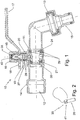
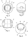
- valve (11) body of the valve, (12) water inlet, (13) outlet, (14) fitting, (15) shaft, (16) cap, (17) mantle, (18) hole, (19) hole, (20) neck, (21) sphere, (22) outer surface of the sphere (21), (23) hole, (24) outlet, (25) pin, (26) shaft, (27) tab, (28) o-rings, (29) seating, (30) inlet, (31) hole, (32) hole, (33) extensions, (34) recesses, (35) upper shaft (17), (36-37) contact zones, (38) channel, (39) hole, (40) seal, (41) pin head (25).
- the valve (10) is coupled to a fitting (14) through which the liquid enters the body (11) of the valve (10), entering through the hole (12) and leaving through the outlet pipe (13), after passing through the flow control system, consisting among other things of a lever (17), attached to the body of the shaft (15), the latter (15) being mounted on the inside of the body (11) with the aid of o-rings (28), and the sphere (21) being attached to the end of the shaft (15) and the air being introduced into the channel (38) with the aid of the hole (39).
- the sphere (21) rotates inside the body (11) by turning the lever (17), the sphere (21) sliding thanks to the joints in the form of seating (29), which partially surround the surface (22) of the sphere (21).
- the surface (22) of the sphere (21) has different openings dimensioned so that the diameter of the hole (30) for the inflow of liquid into the sphere (21) is smaller than the outlet hole (24), respectively, as shown in Figure 3 , the shaft (15) entering through the hole (23) projected in the body of the sphere (21).
- the cap (16) is removed from the top of the valve (10), as shown in Figure 1 .
- the neck (20) of the valve (10) body (11) has a tab (27) provided with a hole (19), and the flow control lever (17) passing through the inside of the valve (10) from the inlet (12) with another hole (18), so that in a certain position of (17) the valve (10) it remains closed, this position being latched by a pin (35) comprising a head (41) shaft (26), as shown in Figure 2 , so that the user can insert this pin (25) and the shaft (26) through the holes (18-19), blocking the movement of the lever (17).
- a conventional padlock can be passed through these holes (18-19), preventing unauthorized use of the liquid flowing through the valve (10).
- valve (10) The operation of the valve (10) is as follows; when the user turns the lever (17) from the closed position in which the lever (17) is perpendicular to the body (11), at which time the lever (17) is at an angle of 90° to the direction of flow of the liquid, the shaft (15) and the sphere (21) rotate, so that the surfaces (36-37) that initially, in this closed position, fully block the passage of the liquid from the inlet (12), coinciding perfectly with the seating (29), with this rotation the liquid inlet (30) and outlet (24) holes gradually start to emerge in relation to the seal in the form of seating (29), allowing the liquid to flow through the valve (10) outlet (13), there being an intermediate position in which a small turn of the lever (17) causes the zone (36) to block the passage of the liquid but with the zone (37) continuing to coincide partially with the seating (29), allowing the outflow of any liquid that may have remained inside the sphere (21), or, even if part of this liquid remains inside the sphere (21), when it freezes it can expand because it is not
Landscapes
- Engineering & Computer Science (AREA)
- General Engineering & Computer Science (AREA)
- Mechanical Engineering (AREA)
- Preventing Unauthorised Actuation Of Valves (AREA)
- Taps Or Cocks (AREA)
Claims (3)
- Absperrventil (10) mit Frostschutzsystem, dessen Hauptelemente unter anderem einen Körper (11) des Ventils (10) umfassen, der im Inneren mit der Hilfe von Abdichtungen in der Form eines Sitzes (29) eine Kugel (21) aufnimmt, die sich relativ zu dem Sitz (29) dreht, mittels einer Welle (15), die in die Kugel (21) eingefügt ist, an deren Ende sich als Regelungseinrichtung ein Hebel (17) befindet, dessen Drehung den Durchlass von Wasser erlaubt oder verhindert, zusätzlich zum Erhöhen oder Verringern des Flusses, wobei die Außenoberfläche (22) der Kugel (21) jeweilige Öffnungen aufweist, die abgemessen sind, so dass der Durchmesser eines Lochs (30) für den Einfluss von Wasser in die Kugel (21) jeweils kleiner ist als ein Auslassloch (24), wobei die Welle (15) durch ein Loch (23) eindringt, das in den Körper der Kugel (21) vorsteht, wobei es an der Außenoberfläche der Kugel (21) Kontaktzonen (36-37) gibt, wobei die Abdichtungen in der Form des Sitzes (29) im Inneren des Körpers (11) des Ventils (10) aufgenommen sind, dadurch gekennzeichnet, dass die Welle (15) ein Loch (39) umfasst, das einen Kanal (38) definiert und das Absperrventil ferner eine Abdeckung (16) umfasst, die konfiguriert ist, um den oberen Teil der Welle (15) zu bedecken, so dass der Einfluss von Luft in die Kugel (21) sichergestellt wird durch Entfernen der Abdeckung (16) und Ermöglichen, dass Luft durch den Kanal (38) verläuft.
- Absperrventil (10) mit Frostschutzsystem gemäß Anspruch 1, dadurch gekennzeichnet, dass das Ventil (10) mit einem Anschlusselement (14) gekoppelt ist, durch das die Flüssigkeit in den Körper (11) des Ventils (10) eindringt, die durch ein Loch (12) eindringt und durch ein Auslassrohr (13) austritt, nach einem Verlaufen durch das Flusssteuersystem, das unter anderem aus einem Hebel (17) besteht, der an dem Körper der Welle (15) befestigt ist, wobei die letztere (15) mit der Hilfe von O-Ringen (28) im Inneren des Körpers (11) befestigt ist, und die Kugel (21) an dem Ende der Welle (15) angebracht ist.
- Absperrventil (10) mit Frostschutzsystem gemäß den vorhergehenden Ansprüchen, dadurch gekennzeichnet, dass der Hals (20) des Ventilkörpers (11) einen Vorsprung (27) aufweist, der mit einem Loch (19) versehen ist, und der Flusssteuerhebel (17) mit einem weiteren Loch (18), so dass in einer bestimmten Position des Flusssteuerhebels (17) das Ventil (10) geschlossen bleibt, wobei diese Position entweder durch ein herkömmliches Vorhängeschloss oder einen Stift (35) verriegelt ist, der einen Kopf (41) und eine Welle (26) aufweist, so dass der Nutzer entweder das herkömmliche Vorhängeschloss oder den Stift (35) und die Welle (26) durch die Löcher (18-19) einfügen kann, wodurch die Bewegung des Hebels (17) blockiert wird.
Applications Claiming Priority (1)
| Application Number | Priority Date | Filing Date | Title |
|---|---|---|---|
| ES201230872U ES1077899Y (es) | 2012-08-08 | 2012-08-08 | Valvula de interrupcion con sistema anti helada |
Publications (2)
| Publication Number | Publication Date |
|---|---|
| EP2696121A1 EP2696121A1 (de) | 2014-02-12 |
| EP2696121B1 true EP2696121B1 (de) | 2017-08-16 |
Family
ID=46968454
Family Applications (1)
| Application Number | Title | Priority Date | Filing Date |
|---|---|---|---|
| EP13173093.9A Active EP2696121B1 (de) | 2012-08-08 | 2013-06-20 | Absperrventil mit Einfrierschutzsystem |
Country Status (3)
| Country | Link |
|---|---|
| EP (1) | EP2696121B1 (de) |
| ES (2) | ES1077899Y (de) |
| PT (1) | PT2696121T (de) |
Cited By (1)
| Publication number | Priority date | Publication date | Assignee | Title |
|---|---|---|---|---|
| US11054044B2 (en) * | 2018-02-14 | 2021-07-06 | Fisher Controls International Llc | Ball valve having a ball valve element with rotation control |
Families Citing this family (1)
| Publication number | Priority date | Publication date | Assignee | Title |
|---|---|---|---|---|
| CN113236813B (zh) * | 2021-05-13 | 2022-09-23 | 温州宏泰机械制造有限公司 | 一种用于控制排污的操作阀 |
Family Cites Families (5)
| Publication number | Priority date | Publication date | Assignee | Title |
|---|---|---|---|---|
| US3429553A (en) * | 1964-04-08 | 1969-02-25 | Newport News S & D Co | Adjustable ball valve apparatus |
| US3883113A (en) * | 1974-03-29 | 1975-05-13 | Acf Ind Inc | Fluid control ball valve structure for throttling service |
| US3960168A (en) * | 1975-09-04 | 1976-06-01 | Acf Industries, Incorporated | Valve locking device |
| JP2005114116A (ja) * | 2003-10-10 | 2005-04-28 | Yamatake Corp | 二方ボール弁 |
| SI23349A (sl) * | 2011-01-17 | 2011-10-28 | Franc Firšt | Krogelna pipa z varovalom spreminjanja nastavitve pretoka tekoäśega medija, mehanizmom stopenjske nastavitve pretoka ter vloĺ˝kom, ki omogoäśa linearen in logaritemski pretok tega medija |
-
2012
- 2012-08-08 ES ES201230872U patent/ES1077899Y/es not_active Expired - Fee Related
-
2013
- 2013-06-20 EP EP13173093.9A patent/EP2696121B1/de active Active
- 2013-06-20 ES ES13173093.9T patent/ES2645928T3/es active Active
- 2013-06-20 PT PT131730939T patent/PT2696121T/pt unknown
Non-Patent Citations (1)
| Title |
|---|
| None * |
Cited By (1)
| Publication number | Priority date | Publication date | Assignee | Title |
|---|---|---|---|---|
| US11054044B2 (en) * | 2018-02-14 | 2021-07-06 | Fisher Controls International Llc | Ball valve having a ball valve element with rotation control |
Also Published As
| Publication number | Publication date |
|---|---|
| ES2645928T3 (es) | 2017-12-11 |
| PT2696121T (pt) | 2017-10-06 |
| ES1077899U (es) | 2012-10-24 |
| ES1077899Y (es) | 2013-01-18 |
| EP2696121A1 (de) | 2014-02-12 |
Similar Documents
| Publication | Publication Date | Title |
|---|---|---|
| US20160003126A1 (en) | Internal combustion engine fluid-metering valve assembly | |
| US10590635B2 (en) | Mixing unit and mixer tap including such a mixing unit | |
| US20090108224A1 (en) | Valve | |
| US10754363B2 (en) | Mixing unit, related mixer tap, and method for manufacturing such a mixer tap | |
| CN105102870B (zh) | 锁定装置以及阀装置 | |
| US9897216B1 (en) | Stop valve | |
| KR101892604B1 (ko) | 밸브 조립체 | |
| EP2696121A1 (de) | Absperrventil mit Einfrierschutzsystem | |
| TW201634843A (zh) | 閥上部 | |
| JP5576823B2 (ja) | 水栓並びに水栓の回動規制具及び回動規制方法 | |
| JP2016023704A (ja) | 流路切換弁 | |
| KR101790317B1 (ko) | 프리플로우트 스팀 트랩 | |
| US20140109970A1 (en) | Metal cone plug valve | |
| EP3414483B1 (de) | Verbesserter verteiler für ausgabeeinheiten | |
| KR20120094750A (ko) | 정수기용 온수밸브 | |
| KR101792458B1 (ko) | 동파 방지용 볼밸브 | |
| ES2921878T3 (es) | Válvula de aviación con indicador de estado | |
| WO2011001163A2 (en) | Spherical radiator drainage apparatus | |
| ES2859622T3 (es) | Válvula de cierre de emergencia | |
| RU2659599C1 (ru) | Клапан, в частности клапан теплообменника | |
| EP3193049B1 (de) | Ventil | |
| KR101200263B1 (ko) | 록킹장치를 구비한 볼 밸브 | |
| EP4438929A1 (de) | Ventilkonstruktion | |
| DK180502B1 (en) | Balancing valve for a hydraulic and/or hydro-thermo-sanitary plant and hydraulic and/or hydro-thermo-sanitary plant comprising said balancing valve | |
| KR20090047202A (ko) | 볼 밸브 |
Legal Events
| Date | Code | Title | Description |
|---|---|---|---|
| 17P | Request for examination filed |
Effective date: 20130620 |
|
| AK | Designated contracting states |
Kind code of ref document: A1 Designated state(s): AL AT BE BG CH CY CZ DE DK EE ES FI FR GB GR HR HU IE IS IT LI LT LU LV MC MK MT NL NO PL PT RO RS SE SI SK SM TR |
|
| AX | Request for extension of the european patent |
Extension state: BA ME |
|
| PUAI | Public reference made under article 153(3) epc to a published international application that has entered the european phase |
Free format text: ORIGINAL CODE: 0009012 |
|
| GRAP | Despatch of communication of intention to grant a patent |
Free format text: ORIGINAL CODE: EPIDOSNIGR1 |
|
| STAA | Information on the status of an ep patent application or granted ep patent |
Free format text: STATUS: GRANT OF PATENT IS INTENDED |
|
| INTG | Intention to grant announced |
Effective date: 20170419 |
|
| GRAS | Grant fee paid |
Free format text: ORIGINAL CODE: EPIDOSNIGR3 |
|
| GRAA | (expected) grant |
Free format text: ORIGINAL CODE: 0009210 |
|
| STAA | Information on the status of an ep patent application or granted ep patent |
Free format text: STATUS: THE PATENT HAS BEEN GRANTED |
|
| AK | Designated contracting states |
Kind code of ref document: B1 Designated state(s): AL AT BE BG CH CY CZ DE DK EE ES FI FR GB GR HR HU IE IS IT LI LT LU LV MC MK MT NL NO PL PT RO RS SE SI SK SM TR |
|
| REG | Reference to a national code |
Ref country code: GB Ref legal event code: FG4D |
|
| REG | Reference to a national code |
Ref country code: CH Ref legal event code: EP |
|
| REG | Reference to a national code |
Ref country code: IE Ref legal event code: FG4D |
|
| REG | Reference to a national code |
Ref country code: AT Ref legal event code: REF Ref document number: 919399 Country of ref document: AT Kind code of ref document: T Effective date: 20170915 |
|
| REG | Reference to a national code |
Ref country code: DE Ref legal event code: R096 Ref document number: 602013025019 Country of ref document: DE |
|
| REG | Reference to a national code |
Ref country code: PT Ref legal event code: SC4A Ref document number: 2696121 Country of ref document: PT Date of ref document: 20171006 Kind code of ref document: T Free format text: AVAILABILITY OF NATIONAL TRANSLATION Effective date: 20170929 |
|
| REG | Reference to a national code |
Ref country code: ES Ref legal event code: FG2A Ref document number: 2645928 Country of ref document: ES Kind code of ref document: T3 Effective date: 20171211 |
|
| REG | Reference to a national code |
Ref country code: NL Ref legal event code: MP Effective date: 20170816 |
|
| REG | Reference to a national code |
Ref country code: LT Ref legal event code: MG4D |
|
| REG | Reference to a national code |
Ref country code: AT Ref legal event code: MK05 Ref document number: 919399 Country of ref document: AT Kind code of ref document: T Effective date: 20170816 |
|
| PG25 | Lapsed in a contracting state [announced via postgrant information from national office to epo] |
Ref country code: NL Free format text: LAPSE BECAUSE OF FAILURE TO SUBMIT A TRANSLATION OF THE DESCRIPTION OR TO PAY THE FEE WITHIN THE PRESCRIBED TIME-LIMIT Effective date: 20170816 Ref country code: FI Free format text: LAPSE BECAUSE OF FAILURE TO SUBMIT A TRANSLATION OF THE DESCRIPTION OR TO PAY THE FEE WITHIN THE PRESCRIBED TIME-LIMIT Effective date: 20170816 Ref country code: NO Free format text: LAPSE BECAUSE OF FAILURE TO SUBMIT A TRANSLATION OF THE DESCRIPTION OR TO PAY THE FEE WITHIN THE PRESCRIBED TIME-LIMIT Effective date: 20171116 Ref country code: LT Free format text: LAPSE BECAUSE OF FAILURE TO SUBMIT A TRANSLATION OF THE DESCRIPTION OR TO PAY THE FEE WITHIN THE PRESCRIBED TIME-LIMIT Effective date: 20170816 Ref country code: AT Free format text: LAPSE BECAUSE OF FAILURE TO SUBMIT A TRANSLATION OF THE DESCRIPTION OR TO PAY THE FEE WITHIN THE PRESCRIBED TIME-LIMIT Effective date: 20170816 Ref country code: SE Free format text: LAPSE BECAUSE OF FAILURE TO SUBMIT A TRANSLATION OF THE DESCRIPTION OR TO PAY THE FEE WITHIN THE PRESCRIBED TIME-LIMIT Effective date: 20170816 |
|
| PG25 | Lapsed in a contracting state [announced via postgrant information from national office to epo] |
Ref country code: PL Free format text: LAPSE BECAUSE OF FAILURE TO SUBMIT A TRANSLATION OF THE DESCRIPTION OR TO PAY THE FEE WITHIN THE PRESCRIBED TIME-LIMIT Effective date: 20170816 Ref country code: LV Free format text: LAPSE BECAUSE OF FAILURE TO SUBMIT A TRANSLATION OF THE DESCRIPTION OR TO PAY THE FEE WITHIN THE PRESCRIBED TIME-LIMIT Effective date: 20170816 Ref country code: GR Free format text: LAPSE BECAUSE OF FAILURE TO SUBMIT A TRANSLATION OF THE DESCRIPTION OR TO PAY THE FEE WITHIN THE PRESCRIBED TIME-LIMIT Effective date: 20171117 Ref country code: BG Free format text: LAPSE BECAUSE OF FAILURE TO SUBMIT A TRANSLATION OF THE DESCRIPTION OR TO PAY THE FEE WITHIN THE PRESCRIBED TIME-LIMIT Effective date: 20171116 Ref country code: IS Free format text: LAPSE BECAUSE OF FAILURE TO SUBMIT A TRANSLATION OF THE DESCRIPTION OR TO PAY THE FEE WITHIN THE PRESCRIBED TIME-LIMIT Effective date: 20171216 Ref country code: RS Free format text: LAPSE BECAUSE OF FAILURE TO SUBMIT A TRANSLATION OF THE DESCRIPTION OR TO PAY THE FEE WITHIN THE PRESCRIBED TIME-LIMIT Effective date: 20170816 |
|
| PG25 | Lapsed in a contracting state [announced via postgrant information from national office to epo] |
Ref country code: CZ Free format text: LAPSE BECAUSE OF FAILURE TO SUBMIT A TRANSLATION OF THE DESCRIPTION OR TO PAY THE FEE WITHIN THE PRESCRIBED TIME-LIMIT Effective date: 20170816 Ref country code: DK Free format text: LAPSE BECAUSE OF FAILURE TO SUBMIT A TRANSLATION OF THE DESCRIPTION OR TO PAY THE FEE WITHIN THE PRESCRIBED TIME-LIMIT Effective date: 20170816 Ref country code: RO Free format text: LAPSE BECAUSE OF FAILURE TO SUBMIT A TRANSLATION OF THE DESCRIPTION OR TO PAY THE FEE WITHIN THE PRESCRIBED TIME-LIMIT Effective date: 20170816 |
|
| REG | Reference to a national code |
Ref country code: DE Ref legal event code: R097 Ref document number: 602013025019 Country of ref document: DE |
|
| PG25 | Lapsed in a contracting state [announced via postgrant information from national office to epo] |
Ref country code: EE Free format text: LAPSE BECAUSE OF FAILURE TO SUBMIT A TRANSLATION OF THE DESCRIPTION OR TO PAY THE FEE WITHIN THE PRESCRIBED TIME-LIMIT Effective date: 20170816 Ref country code: IT Free format text: LAPSE BECAUSE OF FAILURE TO SUBMIT A TRANSLATION OF THE DESCRIPTION OR TO PAY THE FEE WITHIN THE PRESCRIBED TIME-LIMIT Effective date: 20170816 Ref country code: SM Free format text: LAPSE BECAUSE OF FAILURE TO SUBMIT A TRANSLATION OF THE DESCRIPTION OR TO PAY THE FEE WITHIN THE PRESCRIBED TIME-LIMIT Effective date: 20170816 Ref country code: SK Free format text: LAPSE BECAUSE OF FAILURE TO SUBMIT A TRANSLATION OF THE DESCRIPTION OR TO PAY THE FEE WITHIN THE PRESCRIBED TIME-LIMIT Effective date: 20170816 |
|
| PLBE | No opposition filed within time limit |
Free format text: ORIGINAL CODE: 0009261 |
|
| STAA | Information on the status of an ep patent application or granted ep patent |
Free format text: STATUS: NO OPPOSITION FILED WITHIN TIME LIMIT |
|
| 26N | No opposition filed |
Effective date: 20180517 |
|
| PG25 | Lapsed in a contracting state [announced via postgrant information from national office to epo] |
Ref country code: SI Free format text: LAPSE BECAUSE OF FAILURE TO SUBMIT A TRANSLATION OF THE DESCRIPTION OR TO PAY THE FEE WITHIN THE PRESCRIBED TIME-LIMIT Effective date: 20170816 |
|
| REG | Reference to a national code |
Ref country code: DE Ref legal event code: R119 Ref document number: 602013025019 Country of ref document: DE |
|
| REG | Reference to a national code |
Ref country code: CH Ref legal event code: PL |
|
| GBPC | Gb: european patent ceased through non-payment of renewal fee |
Effective date: 20180620 |
|
| REG | Reference to a national code |
Ref country code: CH Ref legal event code: AECN Free format text: DAS PATENT WURDE AUFGRUND DES WEITERBEHANDLUNGSANTRAGS VOM 21.02.2019 REAKTIVIERT. Ref country code: CH Ref legal event code: NV Representative=s name: BOHEST AG, CH |
|
| REG | Reference to a national code |
Ref country code: BE Ref legal event code: MM Effective date: 20180630 |
|
| REG | Reference to a national code |
Ref country code: IE Ref legal event code: MM4A |
|
| PG25 | Lapsed in a contracting state [announced via postgrant information from national office to epo] |
Ref country code: MC Free format text: LAPSE BECAUSE OF FAILURE TO SUBMIT A TRANSLATION OF THE DESCRIPTION OR TO PAY THE FEE WITHIN THE PRESCRIBED TIME-LIMIT Effective date: 20170816 Ref country code: LU Free format text: LAPSE BECAUSE OF NON-PAYMENT OF DUE FEES Effective date: 20180620 |
|
| PG25 | Lapsed in a contracting state [announced via postgrant information from national office to epo] |
Ref country code: IE Free format text: LAPSE BECAUSE OF NON-PAYMENT OF DUE FEES Effective date: 20180620 Ref country code: GB Free format text: LAPSE BECAUSE OF NON-PAYMENT OF DUE FEES Effective date: 20180620 Ref country code: FR Free format text: LAPSE BECAUSE OF NON-PAYMENT OF DUE FEES Effective date: 20180630 Ref country code: DE Free format text: LAPSE BECAUSE OF NON-PAYMENT OF DUE FEES Effective date: 20190101 |
|
| PG25 | Lapsed in a contracting state [announced via postgrant information from national office to epo] |
Ref country code: BE Free format text: LAPSE BECAUSE OF NON-PAYMENT OF DUE FEES Effective date: 20180630 |
|
| PG25 | Lapsed in a contracting state [announced via postgrant information from national office to epo] |
Ref country code: MT Free format text: LAPSE BECAUSE OF NON-PAYMENT OF DUE FEES Effective date: 20180620 |
|
| PG25 | Lapsed in a contracting state [announced via postgrant information from national office to epo] |
Ref country code: TR Free format text: LAPSE BECAUSE OF FAILURE TO SUBMIT A TRANSLATION OF THE DESCRIPTION OR TO PAY THE FEE WITHIN THE PRESCRIBED TIME-LIMIT Effective date: 20170816 |
|
| PG25 | Lapsed in a contracting state [announced via postgrant information from national office to epo] |
Ref country code: HU Free format text: LAPSE BECAUSE OF FAILURE TO SUBMIT A TRANSLATION OF THE DESCRIPTION OR TO PAY THE FEE WITHIN THE PRESCRIBED TIME-LIMIT; INVALID AB INITIO Effective date: 20130620 |
|
| PG25 | Lapsed in a contracting state [announced via postgrant information from national office to epo] |
Ref country code: MK Free format text: LAPSE BECAUSE OF NON-PAYMENT OF DUE FEES Effective date: 20170816 Ref country code: HR Free format text: LAPSE BECAUSE OF FAILURE TO SUBMIT A TRANSLATION OF THE DESCRIPTION OR TO PAY THE FEE WITHIN THE PRESCRIBED TIME-LIMIT Effective date: 20170816 Ref country code: CY Free format text: LAPSE BECAUSE OF FAILURE TO SUBMIT A TRANSLATION OF THE DESCRIPTION OR TO PAY THE FEE WITHIN THE PRESCRIBED TIME-LIMIT Effective date: 20170816 |
|
| PG25 | Lapsed in a contracting state [announced via postgrant information from national office to epo] |
Ref country code: AL Free format text: LAPSE BECAUSE OF FAILURE TO SUBMIT A TRANSLATION OF THE DESCRIPTION OR TO PAY THE FEE WITHIN THE PRESCRIBED TIME-LIMIT Effective date: 20170816 |
|
| P01 | Opt-out of the competence of the unified patent court (upc) registered |
Effective date: 20230525 |
|
| PGFP | Annual fee paid to national office [announced via postgrant information from national office to epo] |
Ref country code: PT Payment date: 20250620 Year of fee payment: 13 |
|
| PGFP | Annual fee paid to national office [announced via postgrant information from national office to epo] |
Ref country code: ES Payment date: 20250910 Year of fee payment: 13 |
|
| PGFP | Annual fee paid to national office [announced via postgrant information from national office to epo] |
Ref country code: CH Payment date: 20250701 Year of fee payment: 13 |