EP2696144A2 - Belüftungssystem für Induktionskochfeld - Google Patents
Belüftungssystem für Induktionskochfeld Download PDFInfo
- Publication number
- EP2696144A2 EP2696144A2 EP13173086.3A EP13173086A EP2696144A2 EP 2696144 A2 EP2696144 A2 EP 2696144A2 EP 13173086 A EP13173086 A EP 13173086A EP 2696144 A2 EP2696144 A2 EP 2696144A2
- Authority
- EP
- European Patent Office
- Prior art keywords
- chassis
- cooking appliance
- duct
- airflow
- cooktop
- Prior art date
- Legal status (The legal status is an assumption and is not a legal conclusion. Google has not performed a legal analysis and makes no representation as to the accuracy of the status listed.)
- Withdrawn
Links
- 238000009423 ventilation Methods 0.000 title claims description 30
- 230000006698 induction Effects 0.000 title description 17
- 238000010411 cooking Methods 0.000 claims abstract description 42
- 230000002093 peripheral effect Effects 0.000 claims abstract description 20
- 238000001816 cooling Methods 0.000 claims abstract description 16
- 238000010438 heat treatment Methods 0.000 claims description 12
- 239000012530 fluid Substances 0.000 claims description 5
- 230000001154 acute effect Effects 0.000 claims description 3
- 230000003213 activating effect Effects 0.000 claims 1
- 230000004913 activation Effects 0.000 claims 1
- 238000000034 method Methods 0.000 claims 1
- 239000011521 glass Substances 0.000 description 3
- 238000010276 construction Methods 0.000 description 2
- 239000007787 solid Substances 0.000 description 2
- 239000006227 byproduct Substances 0.000 description 1
- 239000000919 ceramic Substances 0.000 description 1
- 210000005069 ears Anatomy 0.000 description 1
- 238000005485 electric heating Methods 0.000 description 1
- 230000005611 electricity Effects 0.000 description 1
- 239000002241 glass-ceramic Substances 0.000 description 1
- 230000013011 mating Effects 0.000 description 1
- 230000037361 pathway Effects 0.000 description 1
- 239000000779 smoke Substances 0.000 description 1
Images



Classifications
-
- F—MECHANICAL ENGINEERING; LIGHTING; HEATING; WEAPONS; BLASTING
- F24—HEATING; RANGES; VENTILATING
- F24C—DOMESTIC STOVES OR RANGES ; DETAILS OF DOMESTIC STOVES OR RANGES, OF GENERAL APPLICATION
- F24C15/00—Details
- F24C15/10—Tops, e.g. hot plates; Rings
- F24C15/101—Tops, e.g. hot plates; Rings provisions for circulation of air
-
- H—ELECTRICITY
- H05—ELECTRIC TECHNIQUES NOT OTHERWISE PROVIDED FOR
- H05B—ELECTRIC HEATING; ELECTRIC LIGHT SOURCES NOT OTHERWISE PROVIDED FOR; CIRCUIT ARRANGEMENTS FOR ELECTRIC LIGHT SOURCES, IN GENERAL
- H05B6/00—Heating by electric, magnetic or electromagnetic fields
- H05B6/02—Induction heating
- H05B6/10—Induction heating apparatus, other than furnaces, for specific applications
- H05B6/12—Cooking devices
- H05B6/1209—Cooking devices induction cooking plates or the like and devices to be used in combination with them
- H05B6/1245—Cooking devices induction cooking plates or the like and devices to be used in combination with them with special coil arrangements
- H05B6/1263—Cooking devices induction cooking plates or the like and devices to be used in combination with them with special coil arrangements using coil cooling arrangements
-
- H—ELECTRICITY
- H05—ELECTRIC TECHNIQUES NOT OTHERWISE PROVIDED FOR
- H05B—ELECTRIC HEATING; ELECTRIC LIGHT SOURCES NOT OTHERWISE PROVIDED FOR; CIRCUIT ARRANGEMENTS FOR ELECTRIC LIGHT SOURCES, IN GENERAL
- H05B2206/00—Aspects relating to heating by electric, magnetic, or electromagnetic fields covered by group H05B6/00
- H05B2206/02—Induction heating
- H05B2206/022—Special supports for the induction coils
Definitions
- the present disclosure pertains to the art of cooking appliances and, more particularly, to a ventilation system for developing an airflow that cools control elements, as well as an internal chassis portion, of a cooktop, particularly an induction cooktop.
- a typical cooktop includes a frame having secured thereto a plurality of heating elements which are covered by a glass-ceramic panel or other type of cooking surface.
- the cooktop includes a plurality of control elements, each of which is associated with operating a corresponding heating element mounted to the cooktop.
- the cooktop includes openings that enable cooling air to pass through a top portion of the cooktop to draw away heat generated by the heating elements. The airflow can also be directed by the control elements to protect any associated electronics.
- manufacturers mount the control elements in a separate area of the frame. This arrangement eliminates the need for complicated mounting brackets associated with mounting controls or switches alongside the heating elements on the cooktop.
- mounting the control elements remote from the heating elements eliminates, or at least reduces, the need to shield control electronics from heat generated by the heating elements.
- the addition of a separate area dedicated to the controls reduces the overall available surface area of the cooktop. Add to that the need for a cooling air inlet opening, and the available cooking space is considerably reduced.
- the present disclosure is directed to a ventilation system for a cooking appliance, particularly an induction cooktop mounted in a countertop.
- the cooking appliance includes a frame which supports at least one heating element and associated electronic control components.
- the frame may include a peripheral side portion that establishes a chassis upon which is arranged a glass cooktop.
- the peripheral side portion may include at least one opening that allows air to pass into and out of the chassis.
- a trim structure may be provided between the induction cooktop and the countertop in order to lift the cooktop above the upper surface of the countertop and for establishing a substantially peripheral gap.
- at least one of an inner and an outer duct may be provided for the chassis of the cooking appliance, with the inner duct extending over at least a portion of an electronic control box mounted within the chassis.
- the control box may include a plurality of side walls that define a housing for electrical components, and/or a heat sink for the electrical components, associated with controlling the at least one heating element of the cooking appliance.
- at least one outer duct may extend between the countertop and the chassis adjacent an end of the inner duct.
- a flow of cooling air may be drawn into the inner duct in order to draw heat from the electronic components and then delivered to the outer duct, which directs the flow of cooling air to exhaust through a section of the peripheral gap.
- a fan may be mounted within the chassis to establish a negative pressure to cause the air to flow through at least one of the inner and outer ducts.
- the inlet air can be drawn from directly adjacent the chassis or through a section of the peripheral gap and guided through a first outer duct to certain openings in the peripheral side wall of the chassis prior to being let to the inner duct.
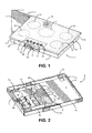
- Figure 1 is a upper right perspective view of an induction cooktop incorporating a ventilation system constructed in accordance with the present disclosure
- FIG. 2 is an upper perspective view of the ventilation system showing inner and outer ducts employed in accordance with a first ventilation embodiment
- Figure 3 is a lower perspective view of the induction cooktop of Figure 1 illustrating an intake arrangement for the first ventilation embodiment
- Figure 4 is a cross-sectional view of a portion of the ventilation system for the induction cooktop of Figures 1-3 ;
- Figure 5 is a partial perspective view of a trim piece employed with the ventilation system of the present disclosure
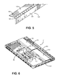
- Figure 6 is an upper perspective view of an induction cooktop chassis incorporating a second ventilation embodiment in accordance with the disclosure
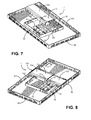
- Figure 7 is an upper perspective view of the induction cooktop chassis of Figure 6 , showing a portion of the second ventilation embodiment removed;
- Figure 8 is an upper perspective view of an induction cooktop chassis incorporating a third ventilation embodiment in accordance with the disclosure.
- Figure 9 is a cross-sectional view of an intake portion of the ventilation embodiments of Figures 5-8 ;
- Figure 10 is an upper perspective view of an induction cooktop chassis incorporating a fourth ventilation embodiment in accordance with the disclosure.
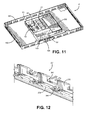
- Figure 11 is an upper perspective view of an induction cooktop chassis incorporating a fifth ventilation embodiment in accordance with the disclosure.
- Figure 12 is a partial perspective view of a trim piece similar to Figure 5 but according to a second embodiment employed with the ventilation system of the present disclosure
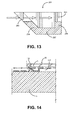
- Figure 13 is a cross-sectional view of the trim piece of Figure 12 ;
- Figure 14 is a partial cross-sectional view illustrating the trim piece of Figure 12 installed between the induction cooktop and a countertop;
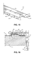
- Figure 15 is a partial perspective view of a trim piece similar to Figure 5 but according to a third embodiment employed with the ventilation system of the present disclosure
- Figure 16 is a partial cross-sectional view illustrating the trim piece of Figure 15 installed between the induction cooktop and a countertop;
- Figure 17 is a partial cross-sectional view illustrating a trim piece according to a fourth embodiment installed between the induction cooktop and a countertop.
- a cooking appliance constructed in accordance with the present disclosure is generally shown at 2.
- the exemplary embodiments are shown in connection with a cooking appliance 2 depicted as an induction cooktop model that is adapted to be arranged in a kitchen countertop, which is partially indicated at 3.
- the cooking appliance 2 is not limited to this particular model type and could also be anyone of various oven range configurations, e.g., both free-standing and slide-in ranges.
- cooking appliance 2 includes a burner box or chassis 4 having a bottom wall or surface 6 and a peripheral side portion 8.
- peripheral side portion 8 extends substantially perpendicularly upward from bottom wall 6 and is constituted by a plurality of upstanding side walls 10-13 formed with at least one spaced opening, as indicated at 17.
- Cooking appliance 2 is also provided with a cooking surface or cooktop 26, which in the embodiment shown, is constituted by a smooth glass/ceramic cooktop.
- Cooktop 26 may be provided with a plurality of cooking zones 29-33 containing heating elements (not separately labeled), illustrated as sheathed, electric heating elements, which are selectively operated by a corresponding plurality of control elements, illustrated as knobs 34-38.
- the control elements may also be buttons, toggles or other such elements.
- cooking appliance 2 could be provided with a downdraft fan unit arranged on cooktop 26 in order to draw away smoke or other byproducts that may be generated during cooking upon cooktop 26.
- a fan or blower assembly 48 which, as will be more fully discussed below, may be employed to create a flow of ventilation air through at least a specified portion of chassis 4.
- control box 53 is illustrated as arranged within chassis 4.
- the control box 53 is not limited to a specific mounting position and may be configured adjacent to and connected with the chassis 4.
- control box 53 is offset to one side of chassis 4, with control box 53 including a bottom 54 and a plurality of side walls 55-58 that collectively define a housing 59.
- housing 59 Arranged within housing 59 are various electronic components, such as generally indicated at 61 and 62, that are associated with control elements 34-38. Due to the heat generated by operation of cooking appliance 2, it is desired to ventilate at least the portion of chassis 4 containing housing 59 in order to protect the various electronic components arranged therein.
- control box 53 contains a heat sink 63 for the electronics in housing 59, with the present disclosure being described in connection with providing a ventilation system to assure an adequate flow of cooling air for the electronics by directing cooling air into housing 59 and across heat sink 63.
- blower assembly 48 when operated, creates a cooling airflow through at least a portion of chassis 4 and it is the manner in which air is directed into, guided through, and exhausted from chassis 4 to which the present disclosure is particularly concerned as discussed more fully below.
- chassis 4 is provided with an opening 65 in bottom 6.
- Blower assembly 48 is positioned directly above opening 65 and leads to an inner duct 72.
- Inner duct 72 is shown to be formed from an upper plate 76 and side plates 77 and 78 which are interconnected to establish a substantially inverted, U-shape.
- inner duct 72 extends over a portion of housing 59, specifically the portion of housing 59 including heat sink 63.
- Inner duct 72 is also provided with a diverging zone 81, which is shown to be provided outside of housing 59 and leads to directly adjacent peripheral side portion 8, of chassis 4.
- an outer duct generally indicated at 85.
- outer duct 85 includes a first end portion 102, which is secured to bottom wall 6 of chassis 4 and an angled wall portion 104 terminating in an upper end portion 108.
- first end portion 102 is fixedly secured to bottom wall 6 of chassis 4 such that angled wall portion 104 is cantilevered from chassis 4.
- wall portion 104 is angled from first end portion 102 through an obtuse angle, while extending at an acute angle with respect to side wall 10 of chassis 4.
- upper end portion 108 abuts an interior body portion 111 of countertop 3 and terminates short of an upper surface 112 of countertop 3.
- trim piece 120 When cooking appliance 2 is mounted in kitchen countertop 3, a gap 117 is established between cooktop 26 and upper surface 112 due to the inclusion of a trim piece or trim member generally indicated at 120.
- FIG 5 Reference will now be made to Figure 5 in describing the construction of trim piece 120 in accordance with a first embodiment of the disclosure.
- trim piece 120 includes a first leg 123, a second leg 124 and a connecting leg 125.
- connecting leg 125 Provided along connecting leg 125 is a series of spaced openings 126.
- Also provided at spaced locations along first leg 123 is a series of supporting nubs 129.
- the openings 126 are not limited to a specific size, shape or quantity and are merely illustrated as a plurality of circular openings.
- trim piece 120 is arranged such that first leg 123 is positioned between cooktop 26 and upper surface 112 of countertop 3, while second leg 124 extends substantially parallel to both inner body portion 111 of countertop 3 and side wall 10 of chassis 4.
- nubs 129 engage upper surface 112 of countertop 3 to establish gap 117, while cooktop 26 rests directly upon first leg 123.
- connecting leg 125 extends around a corner between upper surface 112 and interior body portion 111 of countertop 3 and second leg 124 is spaced from both inner body portion 111 and angled wall portion 104 of outer duct 85.
- second leg 124 is either fixed to or positioned directly against a downturned portion 135 of an interior cover 136 provided in chassis 4.
- blower assembly 48 causes an airflow to be drawn into chassis 4 through opening 65, with the airflow being directed into and through inner duct 72 so as to flow over heat sink 63. Thereafter, the airflow leaves chassis 4 through at least one opening 17 exposed to outer duct 85. The airflow is then guided within outer duct 85 between angled wall portion 104 and second leg 124 of trim piece 120 so as to reach gap 117 between countertop 3 and cooktop 26. Thereafter, the airflow is exhausted through gap 117 as established by trim piece 120 by the inclusion of first leg 123 arranged between cooktop 26 and countertop 3. At the same time, a separate flow of ventilation air can be directed through openings 126 from directly below cooktop 26.
- FIG. 6 and 7 illustrate an embodiment wherein a chassis 4 may be provided with an inner duct 72 defined by a first inner duct section 152 and a second inner duct section 153 that extend longitudinally within chassis 4.
- housing 53 may be provided with cut-outs 156 and 157 as part of housing 59, with inner duct sections 152 and 153 mating with housing 59 at cut-outs 156 and 157 respectively.
- housing 59 would also include heat sink 63 over which inner duct sections 152 and 153 are positioned.
- chassis 4 is provided with a plurality of openings 161 arranged substantially around the entire periphery, with at least one of the openings 161 having an associated louver 162.
- Figures 6 and 7 are only being provided to illustrate another arrangement for the inner duct such that an outer duct 85 and an associated trim piece 120 are simply not shown for the sake of clarity.
- blower assembly 48 can be provided beneath one of first and second inner duct sections 152 and 153 to draw air through openings 161 in one side of chassis 4 and direct the airflow to openings 161 of the other side of chassis 4, with either or both of the inlet and exhaust airflows being directed through an associated outer duct (not shown).
- Figure 8 shows another arrangement wherein the inner duct is defined by inner duct sections 174 and 175 that extend widthwise or across the shorter dimension of the chassis 4.
- outer duct 85 is shown for exhausting the airflow
- a second outer duct 176 is mounted in the same manner as outer duct 85 but provides for an inlet flow of air from between the countertop 3 and the cooktop 26.
- outer duct 176 is constructed in a manner substantially identical to outer duct 85 and therefore corresponding reference numerals have been used in this figure.
- outer duct 176 includes ears 177, which further aid in guiding the airflow into chassis 4.
- a trim piece 178 is simply positioned between cooktop 26 and countertop 3 to establish gap 117.
- trim piece 178 has a solid splash portion 181 extending directly from upper surface 112 of countertop 3 so as to prevent the flow of fluid from directly upon upper surface 112 into gap 117. Still, openings are established within trim piece 178 to permit an airflow directly below cooktop 26 and into gap 117 which can then flow through outer duct 176 and respective openings 161, as guided by louvers 162, and into chassis 4.
- Figure 10 illustrates an embodiment wherein the inner duct is established by a first inner duct portion 192, which is linked to a second inner duct portion 193 through a connecting duct 194.
- the overall outer duct configuration in this embodiment is constituted by a first outer duct 197 and a second outer duct 198.
- Each of the outer ducts 197 and 198 are constructed and mounted according to the same configuration of outer ducts 85 and 176 such that this structure will not be reiterated here.
- blower assembly 48 is provided beneath one of inner ducts 192 or 193.
- blower assembly 48 can be provided beneath first inner duct 192 to draw a flow of air from between cooktop 26 and countertop 3 into gap 117 and through first outer duct 197, with the airflow then being directed over heat sink 63 provided beneath connecting duct 94 and second inner duct 193. Thereafter, the air can be exhausted out of second outer duct 198.
- Figure 11 shows a slightly modified version of this embodiment wherein first inner duct 192 is replaced by an inner duct 200 under which blower assembly 48, although not shown, is positioned and which would be aligned with a lower opening corresponding to opening 65 referenced in connection with Figure 3 . Therefore, instead of receiving an inlet airflow through a first outer duct as set forth in the embodiment of Figure 10 , this embodiment would receive an airflow from beneath chassis 4 as part of the overall ventilation system.
- FIG. 12-14 illustrates a trim piece 251 shown to include an outer trim portion 254 and an inner trim portion 255 which are joined by connecting portion 257.
- Inner and outer portions 254 and 255 constitute splash portions in a manner directly corresponding to that discussed above with respect to the embodiment of Figure 9 .
- outer trim portion 254 is provided with a first set of spaced cut-outs 260, while inner trim portion 255 is provided with a second set of spaced cut-outs 261.
- Cut-outs 260 and 261 can either be aligned or offset.
- trim piece 251 has a solid portion projecting up from upper surface 112 of countertop 3 and establishes an inlet airflow based on the first and second, spaced cut-outs 260 and 261. That is, Figure 14 shows the airflow A by arrows entering directly beneath cooktop 26, while any fluid flow, represented by arrows F, directly on upper surface 112 of countertop 3 will be deflected away from gap 117 by trim piece 251.
- a trim piece 270 is shown to include an outer trim or splash portion 272, which leads to a first plateau 273 upon which cooktop 26 can be directly supported. From first plateau 273, trim piece 270 extends into a downturned portion 274 leading to a base extension 275.
- outer trim portion 272 is provided in outer trim portion 272 .
- first series of openings 278 and provided in downturned portion 274 is a second series of openings 279.
- openings 278 and 279 can either be aligned or offset.
- Figure 17 By way of a still further embodiment wherein a trim piece is located further inward of an edge portion of cooktop 26, reference is made to Figure 17 . More specifically, the embodiment of Figure 17 employs a trim piece 286 having an outer trim or splash portion 288 leading to an angled portion 289 that is provided with openings 290, and a downturned leg 291 which is spaced from outer duct 176.
- outer trim portion 288 functions to prevent fluid from entering beyond trim piece 286 while a lower portion of cooktop 26 is provided with ribs 295 to support cooktop 26 upon trim piece 286 while allowing for an airflow directly between trim piece 286 and cooktop 26, with the airflow being permitted to flow downward through openings 290 in order to lead to outer duct 176 and then flow into the chassis for ventilation purposes in a manner directly corresponding to that described above.
- the same arrangement can be employed for exhausting a ventilation airflow as well.
- the cooking appliance of the present disclosure effectively establishes a ventilation system for providing a flow of cooling air for electronic components of the cooking appliance, with the ventilation system employing the use of at least one trim member, an inner duct and an outer duct, which synergistically combine to enable a cooling airflow to be directed into a chassis of the cooking appliance, pass through the inner and outer ducts, and exhaust through a gap established by the trim member in order to effectively cool the electronic components for extended life.
- various configurations and airflow pathways can be established through the use of the inner and outer ducts and the trim piece, while these components can take various configurations themselves without departing from the various aspects of the disclosure.
- blower assembly can be varied depending upon the configuration of the heating elements and the ducting.
- present disclosure could also be incorporated into a gas appliance, including a gas-under-glass cooktop unit.
Landscapes
- Engineering & Computer Science (AREA)
- Physics & Mathematics (AREA)
- Electromagnetism (AREA)
- Chemical & Material Sciences (AREA)
- Combustion & Propulsion (AREA)
- Mechanical Engineering (AREA)
- General Engineering & Computer Science (AREA)
- Combinations Of Kitchen Furniture (AREA)
- Electric Stoves And Ranges (AREA)
Applications Claiming Priority (1)
| Application Number | Priority Date | Filing Date | Title |
|---|---|---|---|
| US13/546,069 US9841196B2 (en) | 2012-07-11 | 2012-07-11 | Ventilation system for a cooktop |
Publications (2)
| Publication Number | Publication Date |
|---|---|
| EP2696144A2 true EP2696144A2 (de) | 2014-02-12 |
| EP2696144A3 EP2696144A3 (de) | 2017-12-13 |
Family
ID=48747328
Family Applications (1)
| Application Number | Title | Priority Date | Filing Date |
|---|---|---|---|
| EP13173086.3A Withdrawn EP2696144A3 (de) | 2012-07-11 | 2013-06-20 | Belüftungssystem für Induktionskochfeld |
Country Status (2)
| Country | Link |
|---|---|
| US (2) | US9841196B2 (de) |
| EP (1) | EP2696144A3 (de) |
Cited By (4)
| Publication number | Priority date | Publication date | Assignee | Title |
|---|---|---|---|---|
| ES2606718A1 (es) * | 2015-09-21 | 2017-03-27 | Bsh Electrodomésticos España, S.A. | Dispositivo de aparato doméstico |
| KR20180004571A (ko) * | 2016-07-04 | 2018-01-12 | (주)쿠첸 | 전기 렌지의 송풍팬 조립체 |
| WO2019072558A1 (de) * | 2017-10-11 | 2019-04-18 | BSH Hausgeräte GmbH | Kochfeldvorrichtung |
| ES2850081A1 (es) * | 2020-02-21 | 2021-08-25 | Famar Muebles S L | Dispositivo de refuerzo y ventilacion para mobiliario |
Families Citing this family (23)
| Publication number | Priority date | Publication date | Assignee | Title |
|---|---|---|---|---|
| US9841196B2 (en) * | 2012-07-11 | 2017-12-12 | Whirlpool Corporation | Ventilation system for a cooktop |
| FR3018171B1 (fr) * | 2014-03-10 | 2017-01-27 | Eurokera | Plan de travail en vitroceramique |
| GB2525605B (en) * | 2014-04-28 | 2018-10-24 | Flexenable Ltd | Method of bonding flexible printed circuits |
| RU2689410C2 (ru) * | 2014-06-23 | 2019-05-28 | Бревилл Пти Лимитед | Мультиплита |
| ES2648673B1 (es) * | 2016-07-04 | 2018-10-22 | Bsh Electrodomésticos España, S.A. | Dispositivo de campo de cocción |
| EP3445135B1 (de) * | 2017-08-14 | 2020-05-27 | Electrolux Appliances Aktiebolag | Leistungsmodul und garvorrichtung |
| US10993292B2 (en) * | 2017-10-23 | 2021-04-27 | Whirlpool Corporation | System and method for tuning an induction circuit |
| KR102659979B1 (ko) * | 2018-11-08 | 2024-04-22 | 엘지전자 주식회사 | 냉각 구조가 개선된 유도 가열 장치 |
| US11536463B2 (en) | 2019-08-30 | 2022-12-27 | Whirlpool Corporation | Cooktop with side frame members |
| USD1009549S1 (en) * | 2019-09-04 | 2024-01-02 | Samsung Electronics Co., Ltd. | Induction range |
| KR102865919B1 (ko) | 2020-03-12 | 2025-09-26 | 엘지전자 주식회사 | 전기 레인지 및 이에 포함되는 에어 가이드 |
| KR20210115329A (ko) * | 2020-03-12 | 2021-09-27 | 엘지전자 주식회사 | 전기 레인지 |
| KR20220160921A (ko) * | 2021-05-28 | 2022-12-06 | 엘지전자 주식회사 | 전기 레인지 |
| KR102984123B1 (ko) * | 2021-05-28 | 2026-06-30 | 엘지전자 주식회사 | 전기 레인지 |
| US12655986B2 (en) * | 2021-05-28 | 2026-06-16 | Lg Electronics Inc. | Electric range |
| US12435879B2 (en) * | 2021-05-28 | 2025-10-07 | Lg Electronics Inc. | Electric range |
| US12543886B1 (en) * | 2021-08-03 | 2026-02-10 | Tyler R. Patterson | Thermal serving station for countertop |
| CN114383156B (zh) * | 2022-01-11 | 2025-09-09 | 宁波方太厨具有限公司 | 一种集成烹饪灶 |
| USD1034041S1 (en) * | 2022-03-17 | 2024-07-09 | Whirlpool Corporation | Electric cooktop |
| DE102022128975A1 (de) * | 2022-11-02 | 2024-05-02 | Miele & Cie. Kg | Induktionskochfeld |
| DE102022128987A1 (de) * | 2022-11-02 | 2024-05-02 | Miele & Cie. Kg | Induktionskochfeld |
| USD1043227S1 (en) * | 2023-03-03 | 2024-09-24 | Meneghetti S.P.A. Unipersonale | Cooktop |
| USD1082417S1 (en) * | 2023-05-15 | 2025-07-08 | Guangdong Sheng Bao Industrial Co., Ltd. | Grill oven |
Family Cites Families (26)
| Publication number | Priority date | Publication date | Assignee | Title |
|---|---|---|---|---|
| US3927658A (en) * | 1974-12-19 | 1975-12-23 | Gen Electric | Self-locking trim frame for built-in cooktop |
| JPS57109291A (en) * | 1980-12-26 | 1982-07-07 | Matsushita Electric Industrial Co Ltd | Induction heating cooking device |
| US4415788A (en) | 1981-06-08 | 1983-11-15 | Jenn-Air Corporation | Induction cartridge |
| JPS58178988A (ja) | 1982-04-14 | 1983-10-20 | 松下電器産業株式会社 | 調理器ユニツト |
| US4549052A (en) * | 1984-01-12 | 1985-10-22 | The Maytag Company | Cooling system for an induction cooking cartridge |
| JPS61105036A (ja) | 1984-10-29 | 1986-05-23 | Matsushita Electric Ind Co Ltd | 調理器ユニツト |
| JPS61110820A (ja) * | 1984-11-02 | 1986-05-29 | Matsushita Electric Ind Co Ltd | 加熱調理器 |
| FR2641061B1 (de) * | 1988-12-27 | 1991-03-01 | Cepem Cie Europ Equip Menager | |
| JPH02234384A (ja) * | 1989-03-07 | 1990-09-17 | Matsushita Electric Ind Co Ltd | 誘導加熱調理器 |
| FR2714961B1 (fr) * | 1994-01-12 | 1996-04-12 | Scholtes Ets Eugen | Système de ventilation pour table de cuisson ou analogue. |
| EP0675672A1 (de) * | 1994-03-31 | 1995-10-04 | Superluck Electrics Corp. | Wärmeausstrahllvorrichtung für Induktionsheizer |
| US6410892B1 (en) * | 2001-06-19 | 2002-06-25 | Bsh Home Appliances Corporation | Cooktop having a flat glass ceramic cooking surface |
| US6600139B2 (en) * | 2001-06-19 | 2003-07-29 | Bsh Home Appliances Corporation | Appliance control protection apparatus |
| JP4114622B2 (ja) | 2004-03-16 | 2008-07-09 | 松下電器産業株式会社 | 組み込み式加熱調理器 |
| US7049552B2 (en) * | 2004-06-04 | 2006-05-23 | Maytag Corporation | Ventilation system for a cooking appliance |
| KR100644062B1 (ko) * | 2004-08-16 | 2006-11-10 | 엘지전자 주식회사 | 유도 가열 조리기 |
| US7687748B2 (en) | 2005-08-01 | 2010-03-30 | Western Industries, Inc. | Induction cook top system with integrated ventilator |
| US8872077B2 (en) | 2005-08-01 | 2014-10-28 | Western Industries, Inc. | Low profile induction cook top with heat management system |
| KR100793794B1 (ko) * | 2006-04-20 | 2008-01-11 | 엘지전자 주식회사 | 조리기기 |
| KR101291428B1 (ko) * | 2006-12-14 | 2013-07-30 | 엘지전자 주식회사 | 조리기기 |
| DE102007055312A1 (de) * | 2007-11-20 | 2009-05-28 | BSH Bosch und Siemens Hausgeräte GmbH | Anordnung mit einem Kochfeld und einer Arbeitsplatte |
| US8269148B2 (en) * | 2008-09-25 | 2012-09-18 | Electrolux Home Products, Inc. | Cooktop with forced convection cooling |
| TWI367719B (en) * | 2009-03-02 | 2012-07-01 | Delta Electronics Inc | Electric device and circling dissipating system using the same |
| US9175861B2 (en) * | 2012-06-25 | 2015-11-03 | Western Industries, Inc. | Cook top with a ventilation system and a blower mount therefor |
| US9841196B2 (en) * | 2012-07-11 | 2017-12-12 | Whirlpool Corporation | Ventilation system for a cooktop |
| US20140150771A1 (en) * | 2012-12-05 | 2014-06-05 | Bsh Home Appliances Corporation | Cooktop ventilation and cooling system |
-
2012
- 2012-07-11 US US13/546,069 patent/US9841196B2/en active Active
-
2013
- 2013-06-20 EP EP13173086.3A patent/EP2696144A3/de not_active Withdrawn
-
2017
- 2017-12-07 US US15/834,563 patent/US10865995B2/en active Active
Non-Patent Citations (1)
| Title |
|---|
| None |
Cited By (5)
| Publication number | Priority date | Publication date | Assignee | Title |
|---|---|---|---|---|
| ES2606718A1 (es) * | 2015-09-21 | 2017-03-27 | Bsh Electrodomésticos España, S.A. | Dispositivo de aparato doméstico |
| EP3144596A3 (de) * | 2015-09-21 | 2017-07-26 | BSH Hausgeräte GmbH | Haushaltsgerätevorrichtung |
| KR20180004571A (ko) * | 2016-07-04 | 2018-01-12 | (주)쿠첸 | 전기 렌지의 송풍팬 조립체 |
| WO2019072558A1 (de) * | 2017-10-11 | 2019-04-18 | BSH Hausgeräte GmbH | Kochfeldvorrichtung |
| ES2850081A1 (es) * | 2020-02-21 | 2021-08-25 | Famar Muebles S L | Dispositivo de refuerzo y ventilacion para mobiliario |
Also Published As
| Publication number | Publication date |
|---|---|
| US9841196B2 (en) | 2017-12-12 |
| EP2696144A3 (de) | 2017-12-13 |
| US20180100658A1 (en) | 2018-04-12 |
| US20140014649A1 (en) | 2014-01-16 |
| US10865995B2 (en) | 2020-12-15 |
Similar Documents
| Publication | Publication Date | Title |
|---|---|---|
| US10865995B2 (en) | Ventilation system for induction cooktop | |
| US7049552B2 (en) | Ventilation system for a cooking appliance | |
| CN102239365B (zh) | 具有强制对流冷却的灶具 | |
| CN110179324B (zh) | 烹饪装置 | |
| US6600139B2 (en) | Appliance control protection apparatus | |
| US20120152228A1 (en) | Method and apparatus for the thermal protection of led light modules in a range hood appliance | |
| EP2918917A1 (de) | Haushaltsgargerät | |
| CA2883500A1 (en) | Home cooking appliance having an exhaust channel | |
| CN100545519C (zh) | 壁面安装型微波炉 | |
| US20150323194A1 (en) | Home cooking appliance having a rear exhaust louver | |
| US6575157B1 (en) | Heat shielding system for downdraft cooktop fan | |
| US11428417B2 (en) | Home cooking appliance having a cooling fan air guide | |
| US6852963B2 (en) | Wall-mounted type microwave oven | |
| CN112944416B (zh) | 烹饪装置 | |
| CN112914348A (zh) | 烹饪装置 | |
| JP2002228156A (ja) | 電子レンジの電装室構造 | |
| CN115721170B (zh) | 烹饪器具 | |
| CN112954840B (zh) | 烹饪装置 | |
| JP2010277906A (ja) | 誘導加熱調理器 | |
| CN218237549U (zh) | 烹饪装置及集成灶 | |
| CN216079908U (zh) | 一种具有烹饪装置的集成灶 | |
| CN223388622U (zh) | 一种散热效果好的电磁炉 | |
| CN112393281A (zh) | 嵌入式烹饪器具及烹饪系统 | |
| CN223663366U (zh) | 一种集成灶 | |
| CN218820579U (zh) | 灶具模块和集成灶 |
Legal Events
| Date | Code | Title | Description |
|---|---|---|---|
| AK | Designated contracting states |
Kind code of ref document: A2 Designated state(s): AL AT BE BG CH CY CZ DE DK EE ES FI FR GB GR HR HU IE IS IT LI LT LU LV MC MK MT NL NO PL PT RO RS SE SI SK SM TR |
|
| AX | Request for extension of the european patent |
Extension state: BA ME |
|
| PUAI | Public reference made under article 153(3) epc to a published international application that has entered the european phase |
Free format text: ORIGINAL CODE: 0009012 |
|
| PUAL | Search report despatched |
Free format text: ORIGINAL CODE: 0009013 |
|
| AK | Designated contracting states |
Kind code of ref document: A3 Designated state(s): AL AT BE BG CH CY CZ DE DK EE ES FI FR GB GR HR HU IE IS IT LI LT LU LV MC MK MT NL NO PL PT RO RS SE SI SK SM TR |
|
| AX | Request for extension of the european patent |
Extension state: BA ME |
|
| RIC1 | Information provided on ipc code assigned before grant |
Ipc: F24C 15/10 20060101AFI20171107BHEP |
|
| STAA | Information on the status of an ep patent application or granted ep patent |
Free format text: STATUS: THE APPLICATION HAS BEEN PUBLISHED |
|
| STAA | Information on the status of an ep patent application or granted ep patent |
Free format text: STATUS: THE APPLICATION IS DEEMED TO BE WITHDRAWN |
|
| 18D | Application deemed to be withdrawn |
Effective date: 20180614 |