EP2696183A2 - Dispositif de surveillance des fuites et procédé de surveillance des fuites dans une conduite de chauffage à distance - Google Patents
Dispositif de surveillance des fuites et procédé de surveillance des fuites dans une conduite de chauffage à distance Download PDFInfo
- Publication number
- EP2696183A2 EP2696183A2 EP13156171.4A EP13156171A EP2696183A2 EP 2696183 A2 EP2696183 A2 EP 2696183A2 EP 13156171 A EP13156171 A EP 13156171A EP 2696183 A2 EP2696183 A2 EP 2696183A2
- Authority
- EP
- European Patent Office
- Prior art keywords
- resistance
- measuring
- monitoring device
- leakage monitoring
- unit
- Prior art date
- Legal status (The legal status is an assumption and is not a legal conclusion. Google has not performed a legal analysis and makes no representation as to the accuracy of the status listed.)
- Withdrawn
Links
- 238000010438 heat treatment Methods 0.000 title claims abstract description 42
- 238000000034 method Methods 0.000 title claims abstract description 7
- 238000001514 detection method Methods 0.000 title description 3
- 238000005259 measurement Methods 0.000 claims abstract description 54
- 238000009413 insulation Methods 0.000 claims abstract description 51
- 239000004020 conductor Substances 0.000 claims abstract description 26
- 238000012544 monitoring process Methods 0.000 claims abstract description 14
- 238000012806 monitoring device Methods 0.000 claims description 68
- 238000011156 evaluation Methods 0.000 claims description 49
- 238000002955 isolation Methods 0.000 claims description 9
- 230000008878 coupling Effects 0.000 claims description 2
- 238000010168 coupling process Methods 0.000 claims description 2
- 238000005859 coupling reaction Methods 0.000 claims description 2
- 238000012545 processing Methods 0.000 claims description 2
- 238000012423 maintenance Methods 0.000 description 9
- 229920005830 Polyurethane Foam Polymers 0.000 description 6
- 239000004698 Polyethylene Substances 0.000 description 5
- 230000004913 activation Effects 0.000 description 5
- RYGMFSIKBFXOCR-UHFFFAOYSA-N Copper Chemical compound [Cu] RYGMFSIKBFXOCR-UHFFFAOYSA-N 0.000 description 4
- 229910000831 Steel Inorganic materials 0.000 description 4
- 230000000694 effects Effects 0.000 description 4
- 230000001681 protective effect Effects 0.000 description 4
- 238000000926 separation method Methods 0.000 description 4
- 239000010959 steel Substances 0.000 description 4
- XLYOFNOQVPJJNP-UHFFFAOYSA-N water Substances O XLYOFNOQVPJJNP-UHFFFAOYSA-N 0.000 description 4
- 230000006378 damage Effects 0.000 description 3
- 238000010586 diagram Methods 0.000 description 3
- 230000008901 benefit Effects 0.000 description 2
- 238000010276 construction Methods 0.000 description 2
- 230000001419 dependent effect Effects 0.000 description 2
- 238000010292 electrical insulation Methods 0.000 description 2
- 230000007257 malfunction Effects 0.000 description 2
- 238000010295 mobile communication Methods 0.000 description 2
- 239000004033 plastic Substances 0.000 description 2
- 229920003023 plastic Polymers 0.000 description 2
- -1 polyethylene Polymers 0.000 description 2
- 229920000573 polyethylene Polymers 0.000 description 2
- 230000007704 transition Effects 0.000 description 2
- 244000089486 Phragmites australis subsp australis Species 0.000 description 1
- QAOWNCQODCNURD-UHFFFAOYSA-N Sulfuric acid Chemical compound OS(O)(=O)=O QAOWNCQODCNURD-UHFFFAOYSA-N 0.000 description 1
- 230000032683 aging Effects 0.000 description 1
- 230000015572 biosynthetic process Effects 0.000 description 1
- 230000001413 cellular effect Effects 0.000 description 1
- 238000006243 chemical reaction Methods 0.000 description 1
- 238000004891 communication Methods 0.000 description 1
- 229910052802 copper Inorganic materials 0.000 description 1
- 239000010949 copper Substances 0.000 description 1
- 230000007797 corrosion Effects 0.000 description 1
- 238000005260 corrosion Methods 0.000 description 1
- 230000007423 decrease Effects 0.000 description 1
- 238000013461 design Methods 0.000 description 1
- 238000004090 dissolution Methods 0.000 description 1
- 230000005611 electricity Effects 0.000 description 1
- 230000007613 environmental effect Effects 0.000 description 1
- 239000006260 foam Substances 0.000 description 1
- 230000006870 function Effects 0.000 description 1
- 239000002184 metal Substances 0.000 description 1
- 229910052751 metal Inorganic materials 0.000 description 1
- 239000000203 mixture Substances 0.000 description 1
- 238000012986 modification Methods 0.000 description 1
- 230000004048 modification Effects 0.000 description 1
- 230000003287 optical effect Effects 0.000 description 1
- 230000000149 penetrating effect Effects 0.000 description 1
- 230000035515 penetration Effects 0.000 description 1
- 229920002635 polyurethane Polymers 0.000 description 1
- 239000004814 polyurethane Substances 0.000 description 1
- 230000008569 process Effects 0.000 description 1
- 150000003839 salts Chemical class 0.000 description 1
- 239000002689 soil Substances 0.000 description 1
- 229910001220 stainless steel Inorganic materials 0.000 description 1
- 239000010935 stainless steel Substances 0.000 description 1
- 238000012360 testing method Methods 0.000 description 1
Images

Classifications
-
- F—MECHANICAL ENGINEERING; LIGHTING; HEATING; WEAPONS; BLASTING
- F17—STORING OR DISTRIBUTING GASES OR LIQUIDS
- F17D—PIPE-LINE SYSTEMS; PIPE-LINES
- F17D5/00—Protection or supervision of installations
- F17D5/02—Preventing, monitoring, or locating loss
- F17D5/06—Preventing, monitoring, or locating loss using electric or acoustic means
-
- G—PHYSICS
- G01—MEASURING; TESTING
- G01M—TESTING STATIC OR DYNAMIC BALANCE OF MACHINES OR STRUCTURES; TESTING OF STRUCTURES OR APPARATUS, NOT OTHERWISE PROVIDED FOR
- G01M3/00—Investigating fluid-tightness of structures
- G01M3/40—Investigating fluid-tightness of structures by using electric means, e.g. by observing electric discharges
-
- G—PHYSICS
- G01—MEASURING; TESTING
- G01M—TESTING STATIC OR DYNAMIC BALANCE OF MACHINES OR STRUCTURES; TESTING OF STRUCTURES OR APPARATUS, NOT OTHERWISE PROVIDED FOR
- G01M3/00—Investigating fluid-tightness of structures
- G01M3/02—Investigating fluid-tightness of structures by using fluid or vacuum
- G01M3/04—Investigating fluid-tightness of structures by using fluid or vacuum by detecting the presence of fluid at the leakage point
- G01M3/16—Investigating fluid-tightness of structures by using fluid or vacuum by detecting the presence of fluid at the leakage point using electric detection means
- G01M3/18—Investigating fluid-tightness of structures by using fluid or vacuum by detecting the presence of fluid at the leakage point using electric detection means for pipes, cables or tubes; for pipe joints or seals; for valves; for welds; for containers, e.g. radiators
Definitions
- the invention relates to a leakage monitoring device for a heat-insulated district heating pipe, in which two electrical conductors are embedded in the longitudinal direction of the pipe in the thermal insulation.
- the invention further relates to a method for leakage monitoring.
- District heating pipes are used to transport a centrally heated heat medium, such as water, to end users.
- the water may typically have a temperature of up to 130 ° C. So that as little heat as possible is lost during transport, the actual transport tubes made of metal, generally steel tubes, are provided with thermal insulation, which frequently comprises PU foam (PU-polyurethane). As external protection, the heat insulation is covered with a plastic jacket tube, which often requires a PE sheath (PE - polyethylene).
- District heating pipes are usually laid underground. Aging, construction or general earthmoving can lead to leaks. In this case, a leakage of the inner tube cause heat medium from the inner tube enters the PU foam. Leakage of the PE jacket can cause soil moisture to enter the PU foam from the outside. In both cases, the moisture penetration of the PU foam leads to the dissolution of salts from the PU foam, which leads to the formation of a galvanic cell or battery. Depending on the foam composition and the penetrating water, a "battery voltage" of around one volt may occur. The forming battery acid also causes a strong corrosion of the steel inner tube.
- Insulated district heating pipes are provided with two electrical conductors guided in the heat insulation in the direction of the pipe run.
- the electrical conductors of the successive pipe sections can be connected to each other, or the electrical conductors are led to the outside.
- the metallic inner tube can be electrically conductively contacted at the connection points.
- a so-called insulation resistance is measured, which lies between the inner tube and the loop. The value of the insulation resistance is greater than about 10 M ⁇ .
- a deviation in the loop resistance indicates an interruption of the loop.
- a deviation in the insulation resistance indicates moisture that has entered the insulation, ie a leak.
- the leakage monitoring device is suitable for permanent connection to a heat-insulated district heating pipe, in which two electrical conductors are embedded in the longitudinal direction of the pipe in the thermal insulation.
- the device thus remains stationary connected to the pipe section to be monitored and can measure continuously or at intervals.
- the leakage monitoring device is equipped with a measuring unit, which has a first measuring connection, to which a metallic inner tube of the district heating pipe can be connected. Furthermore, a second measuring connection is provided, to which a first end of a first electrical conductor of the two electrical conductors can be connected.
- the insulation resistance of the district heating pipe is between the two measuring ports when the leakage monitoring device is connected to the district heating pipe.
- the monitoring device has a reference electrical insulation resistance with a first resistance terminal and a second resistance terminal.
- the reference insulation resistance may be a conventional electrical resistance having a value approximately equal to the expected insulation resistance.
- An electrical resistance measuring unit as part of the leakage monitoring device has a first measuring input and a second measuring input.
- a remote-controlled switch allows the optional coupling of the reference insulation resistance or the first measuring terminal and the second measuring terminal to the resistance measuring unit. Remote control means that the switch can be operated from a remote unit, for example via a radio signal. The advantage of a remote-controlled switch is that there is no need for on-site personnel to operate the switch.
- the remote-controlled switch allows at any time to switch to a defined reference insulation resistance and thus allows, for example, to check the functionality of the resistance measuring unit and more generally the monitoring device. Reliability is significantly increased without the need for on-site maintenance personnel.
- the leakage monitoring method of the present invention in a thermally insulated district heating pipe in which two electrical conductors are longitudinally embedded in the thermal insulation comprises measuring an electrical resistance between a first of the two electrical conductors and a metallic inner pipe of the thermally insulated district heating pipe. In other words, the insulation resistance in the tube is measured. The value of the insulation resistance allows conclusions as to whether or not moisture has penetrated into the heat insulation.
- switching to an electrical reference insulation resistance takes place at predetermined time intervals and / or when a resistance value has been measured which deviates from an expected measurement result. Then, the reference insulation resistance is measured.
- Switching in given time resistances has the advantage that the functionality is regularly checked and a malfunction can be detected early. If resistance readings that are outside an expected range are present, a malfunction of the measuring unit can be specifically excluded or confirmed by switching over.
- the measuring unit further comprises a third measuring terminal, to which a second end of the second electrical conductor of the two electrical conductors can be connected. This then lies between the second and the third measuring connection, the loop, which is formed from the first electrical and the second electrical conductor, provided that the two conductors are electrically conductively connected to one another at a remote end of the tube.
- a reference loop resistor having a third resistor terminal and a fourth resistor terminal, wherein the remote-controlled switch selectively couples the two reference resistors or the three measuring terminals to the resistance measuring unit.
- the resistance measuring unit is completely galvanically isolated from the two or three measuring terminals when the reference resistor or resistors are coupled to the resistance measuring unit via the switch.
- the switch is thus designed so that no electrically conductive connection to the measuring connections, to which the pipe connections are permanently coupled, remains.
- the switch can also serve for activation. For example, if construction work is planned or maintenance work on the district heating pipe is planned, this could have an effect on the monitoring device and, secondly, the ongoing resistance measurement could interfere with any measurements during maintenance work. Due to the possible activation, it is no longer necessary for personnel to disconnect the electrical conductors on site. Since the switch can be operated remotely, it can be switched, for example, from a control panel. Even with a thunderstorm, especially with exposed pipes can be done via the switch an activation, whereby the leakage monitoring device is reliably protected against damage from overvoltages.
- the leakage monitoring device comprises a plurality, in particular up to four, measuring units which allow simultaneous monitoring of a plurality, in particular up to four heat-insulated district heating pipes.
- a pipe for the flow i. the forwarding of the heat medium to the end user
- a pipe for the return i. the return transport of the (cooled) heat medium away from the end user
- parallel At a junction between two pipe sections therefore four pipe sections are present, the so-called left flow, the right flow, the left return and the right return.
- all four pipe sections may be monitored with only one leakage monitoring device.
- the leakage monitoring device comprises an evaluation unit for processing resistance measurement results which were measured by the resistance measuring unit.
- an evaluation unit is sufficient, since this can process the resistance measuring results of a plurality, in particular up to four, measuring units.
- the evaluation unit comprises a radio module which allows receiving and / or transmitting data, in particular according to a mobile radio standard.
- the radio module allows receiving and / or transmitting according to a short message standard, for example SMS (Short Message Standard).
- SMS Short Message Standard
- GSM Global System for Mobile Communications
- GSM Global System for Mobile Communications
- the leakage monitoring device can communicate with a higher-level unit without requiring a communication line.
- the radio module can be coupled to a transmitting antenna, which can be adapted to the respective radio network quality at the planned place of use.
- the evaluation unit may e.g. send the measured values to a higher-level unit at regular intervals or on request via radio.
- the higher-level unit can, for example, receive the measured data from a plurality of evaluation units for different sections of a district heating pipe.
- the evaluation unit can issue a control signal for controlling the switch.
- This control signal the evaluation unit itself, for example, under Generate a timer at predefined times.
- the evaluation unit can also generate the control signal on the basis of evaluation results, for example in the case of implausible measurement results.
- the evaluation unit can also receive a command for generating a control signal for the switch via radio. The latter is particularly interesting for the activation function of the switch. Irrespective of this, the switch can also be controlled directly via radio.
- the leakage monitoring device comprises a device for electrical isolation between the one or more measuring units and the evaluation unit.
- the measuring units are preferably carried out analogously. They are, if there is no activation, in direct contact with the district heating pipes and thus constantly electromagnetic interference, which can lead to unwanted spikes exposed.
- analog modules are generally less prone to interference than digital modules.
- the evaluation unit is advantageously carried out digitally in order to enable a more extensive evaluation of the measurement results, storage, etc. This electronics is much more sensitive to interference voltages. Therefore, the galvanic separation between the measuring units and the evaluation unit protects the evaluation unit against external interference.
- the galvanic isolation device may include optocouplers.
- the galvanic isolation device may also include an isolation transformer.
- a grounding of the measuring unit takes place on an earth potential of the district heating pipes or the.
- a grounding of the evaluation unit can be made to a ground potential of a transmitting antenna coupled to the radio module.
- the resistance measurements on the district heating pipes are subject to many influences and it can easily lead to incorrect measurements. Careful grounding is therefore important for the achievable measurement accuracy.
- the leakage monitoring device also includes a power supply terminal to supply the evaluation unit and the measuring units with electrical energy.
- a device for electrical isolation of the power supply of the evaluation unit and the measuring unit is provided.
- the device may comprise an isolating transformer and / or optocoupler.
- the earth ground of the used voltage supply can serve as reference earth.
- three galvanically isolated potential ranges are provided:
- the measuring unit is earthed to a ground potential of the district heating pipes, the evaluation unit to a ground potential of Transmit antenna and the power supply connection to a ground potential of the used power supply.
- the evaluation unit is designed such that it evaluates the resistance measured values measured by the resistance measuring unit at predetermined time intervals and rejects resistance measured values that are outside of a first predetermined value interval.
- the rejection of non-plausible measurements is important for the accuracy of the measurements under the particular measurement conditions prevailing in district heating pipes. Electromagnetic disturbances can cause extreme outliers in the readings without a problem in the district heating pipes themselves.
- the evaluation unit automatically recognizes that there must be a measurement error due to external circumstances and therefore rejects the corresponding measured value.
- the evaluation unit can be designed such that it forms a resistance mean value from a predefinable number of non-rejected resistance measurement values.
- the resistance average is checked to see if it is within a second predetermined value interval that is less than the first predetermined value interval.
- the resistance mean values can be stored in a memory.
- the memory is a ring memory in which the resistance measurements of a certain period of time, e.g. two weeks, can be stored. In other words, newer readings displace the oldest readings from memory without the need to reset or periodically flush the memory. The last measured values are always available.
- the evaluation unit is designed so that it, when the resistance mean value is outside the second predetermined value interval, outputs a switching signal to the switch.
- the switch thus switches to the reference resistor (s) and the electrical resistance measuring unit is no longer coupled to the district heating pipe.
- a measurement of the reference resistor (s) is performed. If the measured reference values measured after switching are within a predetermined reference value interval, a radio message, in particular an SMS (short message service), is transmitted. In this way, maintenance personnel can be informed that a resistance value was measured at the district heating pipe, which is not within the normal range, the measuring unit as such is functional, as the measurement of the reference resistance has shown. If the reference measured values measured after switching are outside a predetermined reference value interval, a radio message, in particular an SMS, can likewise be transmitted. Through this maintenance personnel can be informed that there is a fault of the measuring unit.
- the evaluation unit may comprise a connection for connection to a data display device, in particular with a screen. This allows the maintenance personnel to read out measurement data themselves at the evaluation unit and / or to carry out a reconfiguration of the evaluation unit.
- FIG. 1 shows a schematic perspective view of a pipe 1, as it comes as a district heating pipe used.
- a metallic inner tube 4 is usually a steel tube, it can be made of stainless steel depending on the application. Through the inner tube 4 flows a heat medium 8, which is hot water or even Steam can act.
- the inner tube 4 is surrounded by a heat insulation 3.
- the thermal insulation may be formed of PU foam.
- the thermal insulation 3 is protected by a surrounding outer shell 2.
- the jacket 2 may be formed of plastic, for example polyethylene.
- wires 5, which are in FIG. 1 are shown connected to a wire loop.
- the district heating pipe 1 is provided with two separate non-insulated wires 5, which are embedded in the non-conductive heat insulation 3.
- the wires 5 extend in the longitudinal direction of the inner tube 4 and do not touch this.
- One of the two wires 5 may be made of copper, while the second wire 5 may be a tinned wire.
- Wires 5 serve as measuring wires.
- the wires 5 of a link are connected in a loop, as in FIG FIG. 1 shown.
- wires 5 of several sections in succession, ie copper wire with copper wire and tinned wire with tinned wire and only at the end of the several sections by a merger of the copper wire and the tinned wire to form a loop.
- the wires 5 then have a free wire end 6 and a free wire end 7.
- Wire ends 6 and 7 can be connected to a leakage monitoring device 10 according to the invention, as in FIGS. 3 to 6 shown, coupled.
- This allows the measurement of the so-called loop resistance, which is on the order of about 100 ⁇ , depending on the wires used and the length of the monitored pipe section.
- a band clamp 9 may be placed, as it is also used for grounding.
- the inner tube 4 can be connected to the leakage monitoring device 10 according to the invention and between the inner tube 4 and one of the wires 5, and the wire loop, the so-called insulation resistance can be measured.
- the electrical insulation resistance is on the order of about 10 M ⁇ .
- FIG. 2 shows a schematic cross section through the district heating pipe 1. Also in FIG. 2 the wires 5 are shown connected to a wire loop. In the steel inner tube 4, the heat medium flows 8. The insulation 3 surrounds the inner tube 4 and the jacket 2 surrounds the insulation 3. To one end of the inner tube 4 is a band clip 9, the over a wire can be connected to the leakage monitoring device 10 according to the invention.
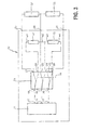
- FIG. 3 schematically shows a measuring unit 12 as part of an embodiment of the leakage monitoring device 10 according to the invention, which is to allow an understanding of the switching between the district heating pipe and reference resistors.
- an electrical resistance measuring unit 11, a switch 13, a reference insulation resistance 27 and a reference loop resistance 28 are shown in the measuring unit 9.
- FIG. 3 the electrical resistances to be measured in the district heating pipe, more precisely an insulation resistance 32 and a loop resistance 33.
- the measuring unit 9 comprises a first measuring connection 29 and a second measuring connection 30.
- the metallic inner tube 4 can be connected via the band clamp 9 to the first measuring connection 29.
- a first end 6 of the wire loop 5 can be connected to the second measuring connection 30.
- the insulation resistance 32 lies between the first measuring terminal 29 and the second measuring terminal 30.
- the measuring unit 9 further comprises a third measuring terminal 31 to which a second end 7 of the wire loop 5 can be connected. This is the loop resistance 33 between the second measurement port 30 and the third measurement port 31.
- a leakage monitoring is in principle also possible if only the insulation resistance is measured.
- the insulation resistance decreases when moisture has penetrated into the thermal insulation.
- the loop resistance gives information about whether there is an interruption of the measuring loop. An interruption of the measurement loop can lead to a faulty measurement of the insulation resistance.
- the third measuring connection 31 is therefore advantageous, but not absolutely necessary for the invention.
- the reference insulation resistor 27 has a first resistance terminal W1 and a second resistance terminal W2. It has a value of about 1 M ⁇ .
- the reference loop resistor 28 has a third resistor terminal W3 and a fourth resistor terminal W4. The reference loop resistor 28 is only necessary if a third measuring terminal 31 is provided. It has a value of about 10 ⁇ .
- the third resistance terminal W3 is electrically coupled to the second resistance terminal W2.
- the resistance measuring unit 11 comprises a first measuring input 15, a second measuring input 16 and a third measuring input 17.
- the third measuring input 17 is only necessary if a loop resistance measurement is also provided.
- the switch 13 includes a first switch terminal 18 connected to the first measurement input 15, a second switch terminal 21 connected to the first measurement terminal 29, and a third switch terminal 22 connected to the first resistor terminal W1.
- the switch 13 is configured to connect the first switch terminal 18 to either the second switch terminal 21 or to the third switch terminal 22 depending on a switching signal indicated by a reference 14.
- the switch 13 is remotely controllable.
- the switching signal 14 may come from another unit of the leakage monitoring device.
- the switching signal 14 can be transmitted via radio to the leakage monitoring device 10.
- the switch 13 further includes a fourth switch terminal 19 connected to the second measurement input 16, a fifth switch terminal 23 connected to the second measurement terminal 30, and a sixth switch terminal 24 connected to the second resistor terminal W2.
- the switch 13 is designed such that, depending on the switching signal 14, it connects the fourth switch connection 19 either to the fifth switch connection 23 or to the sixth switch connection 24.
- the switch 13 further includes a seventh switch terminal 20 connected to the third measurement input 17, an eighth switch terminal 25 connected to the third measurement terminal 31, and a ninth switch terminal 26 connected to the fourth resistor terminal W4.
- the switch 13 is designed to connect the seventh switch terminal 20 to either the eighth switch terminal 25 or the ninth switch terminal 26, depending on the switching signal 14.
- the switching operations are coupled, ie the switch 13 connects either the first switch terminal 18 to the second switch terminal 21 and the fourth switch terminal 19 to the fifth switch terminal 23 and the seventh switch terminal 20 to the eighth switch terminal 25, so that the measuring terminals 29, 30 and 31 are connected to the measuring inputs 15, 16 and 17, or the switch 13 connects the first switch terminal 18 to the third switch terminal 22 and the fourth switch terminal 19 to the sixth switch terminal 24 and the seventh switch terminal 20 to the ninth switch terminal 26, so that the resistor terminals W1, W2, W3 and W4 are connected to the measurement inputs 15, 16 and 17.
- the reference resistors 27 and 28 are measured in one switch position so the resistors 32, 33 of the tube 1 and in the other switch position.
- the tube 1 is completely galvanically isolated from the resistance measuring unit 11. Switching to the reference resistors thus also offers a so-called release of the tube 1, which is very valuable for maintenance.
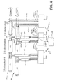
- FIG. 4 shows schematically the use of a plurality of leakage monitoring devices 10A, 10B and 10C for monitoring a larger segmented in district sections Fernowskirohres.
- Pipe 40 serves the flow, ie the transport of the heat medium to the customer.
- Tube 50 is used for the return, ie the transport of the usually cooled heat medium away from the customer.
- a 1st, a 2nd and a 3rd stretch are shown.
- first section In the first section are a pipe section 41 for the flow and a pipe section 51 for the return.
- second section In the second section are a pipe section 42 for the flow and a pipe section 52 for the return.
- 3rd section In the 3rd section are a pipe section 43 for the flow and a pipe section 53 for the return.
- the leakage monitoring device 10C is provided for monitoring the 1st route section, ie, the pipe sections 41 and 51.
- the wire ends are in FIG. 4 on the right side of the pipe sections 41, 51 led to the leakage monitoring device.
- the wires at S1, S2 are connected to a wire loop 5CR and 5CV, respectively.
- the leak monitoring device 10C has measuring ports 29CR, 30CR and 31CR to which the terminals of the wire loop 5CR and the inner pipe of the return pipe section 51 are connected.
- the leakage monitoring device 10C further has measurement ports 29CV, 30CV and 31CV to which the terminals of the wire loop 5CV and the inner pipe of the flow pipe section 41 are connected.
- the leakage monitoring device 10C comprises two measuring units 9, as in FIG FIG. 3 shown, with which the resistances of the two pipe sections 41, 51 are measured separately.
- the leak monitoring device 10C may communicate with a superordinated unit 120 via a radio signal F1.
- the parent unit 120 may be at the operator of the district heating network.
- the leakage monitoring device 10B is provided for monitoring the second route section, ie the pipe sections 42 and 52.
- both pipe sections again electrical conductors or wires are laid in the insulation, as with respect to Figures 1 and 2 already explained in detail.
- the wire ends are in FIG. 4 on the right side of the pipe sections 42, 52 led to the leakage monitoring device 10B.
- the leakage monitoring device 10B is disposed at the place of a consumer to which branch pipes 44 and 54 lead.
- the wires routed in the pipe sections 42 and 52 are first connected to the wires routed in the branch pipes 44 and 54. Their free ends are led to the leak monitoring device 10B. Leakage monitoring device 10B thus monitors both the tubes 42 and 52 and the tubes 44 and 54.
- the leakage monitoring device 10B has measuring ports 29BR, 30BR and 31 BR, to which the terminals of the wire loop 5BR are connected, and the inner tube of the return tube section 52 via the inner tube of the branch pipe 54. That is, the two inner tubes of the tubes 52 and 54 are electrically connected to each other.
- the leakage monitoring device 10B further has measuring ports 29BV, 30BV and 31 BV to which the terminals of the wire loop 5BV and the interconnected inner tubes of the flow pipe section 42 and the branch pipe 44 are connected.
- the leakage monitoring device 10B also includes two measuring units 9, as in FIG FIG. 3 shown, with which separately the resistances of the two pipe sections 42 44 and 52 measured at 54.
- the leakage monitoring device 10B may also communicate with the superordinate unit 120 via a radio signal F2.
- the leakage monitoring devices 10B and 10C are combined to form a leakage monitoring device comprising four measuring units 9.
- This summarized leakage monitoring device 10 could be installed at the location of the leakage monitor 10B.
- the surveillance wires carried out in the tube sections 41 and 51 would then have to be placed on the in FIG. 4 right side of the pipe sections 41 and 51 are each connected to a loop.
- the wire ends are then fed to the combined leakage monitoring device 10.
- the pooled leak monitor will then have a total of 12 gauge connections.
- the third route section is monitored accordingly with a leakage monitoring device 10A, which will not be explained in detail. Because all three leakage monitoring devices are connected via radio to a central unit 120, a central evaluation of the measurement results can take place.
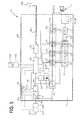
- FIG. 5 shows a block diagram of an embodiment of a leakage monitoring device 10 according to the invention, comprising a measuring unit 12, an evaluation unit 80 and a power supply 93.
- the measuring unit 12 has already been described with reference to FIG. 3 explained in detail.
- FIG. 5 is purely schematically indicated the pipe to be monitored 1, which is connected via measuring terminals 29, 30 and 31 to the measuring unit 12.
- the reference resistors 27 and 28 are shown purely schematically as a block, as well as switch 13.
- switch 13 and resistance measuring unit 11 may optionally be connected a voltage limiter 63 to the resistance measuring unit 11 against overvoltages, eg caused by electromagnetic interference in the district heating pipe protect.
- the ohmmeter may optionally also include a voltmeter. This can be detected, for example, caused by the battery effect in damp heat insulation voltage.
- the measured values recorded by the ohmometers 61 and 62 and optionally by the voltmeter 60 are transmitted to the evaluation unit 80 via optocouplers 72, 73 and 74.
- a switching signal output by the evaluation unit 80 for switch 13 is transferred via an optocoupler 75 to the measuring unit 12.
- a voltage converter 71 which performs a voltage conversion of, for example 24 volts DC to ⁇ 15 volts DC, is designed as a divider. To put it Optocouplers 72, 73, 74 and 75 together with the isolator 71, a device 70 for electrical isolation between the measuring unit 12 and the evaluation unit 80 ready.
- FIG. 5 only one measuring unit 12 is shown. It should be understood that there may be a plurality of measuring units 9, each of which then separately comprises the components disclosed in US Pat FIG. 5 for a measuring unit 12 are shown. As for FIG. 4 explained, in particular two measuring units 9 for the monitoring of flow and return of a section advantageous, and four measuring units 9 for the simultaneous monitoring of flow and return of two adjacent sections. Even if four measuring units 9 are provided, an evaluation unit 80, which will be described below, is sufficient for the evaluation.
- the evaluation unit 80 comprises a control unit 81, which may be designed as a microprocessor.
- the control unit 81 is connected via a data line, for example a CAN bus, to a block 82, which represents a memory unit and a radio module.
- the memory unit 82 may be implemented as a data logger, i. even have computing capacity.
- the radio module 82 may allow data to be received and / or transmitted over a mobile radio network, in particular via a network according to the GSM standard (Global System for Mobile Communications).
- the radio module 82 can for this purpose have a receiving slot for introducing a so-called SIM card (Subscriber Identity Module), which grants access to a mobile network.
- SIM card Subscriber Identity Module
- the storage unit 82 preferably comprises a ring buffer, i. a memory that, when filled, discards the oldest data and can hold new data for it.
- the storage volume may be designed to receive data for a certain period of time, for example for a week, two weeks or even one month.
- the memory unit 82 is connected to an antenna 100 via a shielded line 101.
- the shielding of the cable is earthed, it is at the ground potential of the antenna.
- the control unit 81 is connected to the optical couplers 72, 73 and 74, that is, the control unit 81 receives the measurement data of the resistance meters 61 and 62 and the tension meter 60.
- the control unit 81 also outputs a switching signal via the optocoupler 75 to the switch 13.
- the control unit 81 may comprise a timer and itself, eg timer-controlled, generate the switching signal. But you can also over the antenna 100 and block 82 receive a switching signal and forward it to switch 13.
- the evaluation unit 80 further comprises a battery 86, which is permanently coupled via a switch 83 to a power supply input of the control unit 81 and is charged via the power supply network. This ensures an emergency power supply if the power supply fails.
- a battery / battery monitoring in the control unit 81 gives a signal to the switch 83 to disconnect the battery, if the battery voltage a fixed battery / or. Battery voltage drops below to avoid damage to the battery.
- a fault message is sent via SMS.
- a unit 85 detects the voltage supply from the power supply network and reports a power failure to the control unit 81 if necessary. Power failures are documented in the memory unit 82 and sent to the higher-level unit when the data is polled via the radio module 82.
- the evaluation unit 80 comprises an interface for connecting a data display device, for example a screen 102.
- a unit 106 represents a CAN bus / USB converter (also CAN bus / RS232 converter). This is required when using a commercially available PC or laptop 102 to adapt the interfaces.
- the unit 106 may be omitted if a CAN bus capable terminal is used.
- the evaluation unit 80 is usually connected via a power supply unit 93 to a voltage network, for. B. a 240 volt / 50 Hertz AC mains connected.
- the connection can be made via a fuse 103 and an electricity meter 104.
- a rectifier 91 is provided, which is designed as a disconnector with protective separation and at the same time takes over the battery charging management, and an optocoupler 92, via which the optional meter also with protective separation to the supplying Network is running.
- the counter readings are fed via this interface to the control unit 81 and read out via the radio module.
- the optional fuse 103 has a potential-free contact with protective separation, this is coupled to the control unit 81. In the event of a failure or manual switch-off of the fuse, a message is sent via the radio module.
- the power supply unit 93 and the evaluation unit 80 are galvanically separated from each other.
- Galvanic isolation between the various components is important because leakage currents can corrupt the readings and leakage currents between the piping network and the protective earth connection of the supplying network can assume magnitudes of indirect lightning effects that can lead to destruction of the device and the connected lines.
- the measurement of the insulation resistance and the loop resistance is subject to various other influences, which are, inter alia, due to the fact that the district heating pipes are laid in the ground. In order to be able to make reliable statements about possible leaks, a high measuring reliability is crucial.
- the control unit 81 is designed to store the measured resistance values of the insulation resistance and possibly the loop resistance at predeterminable time intervals. Furthermore, it can evaluate the measured resistance values measured by the resistance measuring unit 11 at predetermined time intervals and discard resistance measured values which lie outside a first predetermined value interval.
- the first predetermined value interval is very far, it serves to detect so-called outliers, i. Values that are far away from the expected measurement results and are caused by external short-term disturbances. Such non-plausible measured values are discarded.
- an average value is formed. For example, 10 consecutive readings are averaged. This applies to both the loop resistance and the insulation resistance. A permissible resistance interval is defined for both the insulation resistance and the loop resistance. If the mean value lies outside the resistance value interval, a switching signal for switching over of the switch 13 is output in the described embodiment, so that a measurement of the reference resistance values 27 and 28 takes place. This is used to check whether there is an error in the measuring unit. If the measurement shows that the measuring unit is functioning correctly, a signal is output via the radio module 82 and the antenna 100 that signals a faulty value in the resistance measurement.
- a signal is emitted which signals a faulty measuring unit.
- the signals can be given in the form of an SMS.
- the reading outside the allowable resistance interval is stored in memory 82 if there is no error in the measuring unit.
- Resistance average values that are within the second predetermined Value interval, ie the permissible resistance interval are also stored in the memory 82.
- control unit 81 at regular intervals a switching signal to the switch 13, or to the switch 13, if several measuring units 9 are present, so that regularly a self-test by measuring the reference resistors 27 and 28 takes place.
- the emission of a radio signal which signals a faulty measuring unit can take place.
- the storage and radio module 82 may periodically send the stored measurements over the cellular network to a higher-level unit.
- the memory and radio module can also deliver the measured values on request via radio.
- the stored measured values can also be displayed on a connected screen 102.
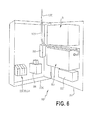
- FIG. 6 shows a possible structural design of a leakage monitoring device 10 according to the invention in a cabinet-like housing 200 having a door 201, the measuring terminals 29, 30 and 31 are housed. Connecting wires to or to be monitored district heating pipes are firmly connected to this electrically conductive. About the power supply 94, the leakage monitoring device 10 with a supply voltage, for. B. be supplied via the local power supply network. In the event of a power failure, the battery 86 is provided.
- the measuring unit 12, or the measuring units 12 are housed in a housing separate from the evaluation unit 80, which also has a separate housing. In another housing is the power supply unit 93. While in FIG. 6 In general, the wiring inside the cabinet is not shown for clarity, a shielded lead 101 is indicated, which leads to the antenna 100, which is mounted on the outside of the cabinet-like housing 200.
- the closed housing 200 secures the leak monitoring device 10 from environmental influences and against unauthorized access and can thus be installed at end customers, the operator of the district heating network can constantly access the measured values and a permanent monitoring is ensured.
- leakage monitoring device 10 described in detail above is merely an exemplary embodiment which can be modified in many different ways by the person skilled in the art without departing from the scope of the invention.
- the use of the indefinite article “on” or “one” does not exclude that the characteristics in question may also be present multiple times.
- the term “unit” and “module” do not exclude that the components in question consist of several interacting sub-components, which may possibly also be spatially distributed.
Landscapes
- Physics & Mathematics (AREA)
- General Physics & Mathematics (AREA)
- Engineering & Computer Science (AREA)
- Acoustics & Sound (AREA)
- Mechanical Engineering (AREA)
- General Engineering & Computer Science (AREA)
- Testing Of Short-Circuits, Discontinuities, Leakage, Or Incorrect Line Connections (AREA)
Applications Claiming Priority (1)
| Application Number | Priority Date | Filing Date | Title |
|---|---|---|---|
| DE102012103747A DE102012103747A1 (de) | 2012-04-27 | 2012-04-27 | Leckage-Überwachungsvorrichtung und Verfahren zur Leckage-Überwachung in einem Fernwärmerohr |
Publications (1)
| Publication Number | Publication Date |
|---|---|
| EP2696183A2 true EP2696183A2 (fr) | 2014-02-12 |
Family
ID=47845721
Family Applications (1)
| Application Number | Title | Priority Date | Filing Date |
|---|---|---|---|
| EP13156171.4A Withdrawn EP2696183A2 (fr) | 2012-04-27 | 2013-02-21 | Dispositif de surveillance des fuites et procédé de surveillance des fuites dans une conduite de chauffage à distance |
Country Status (2)
| Country | Link |
|---|---|
| EP (1) | EP2696183A2 (fr) |
| DE (1) | DE102012103747A1 (fr) |
Cited By (1)
| Publication number | Priority date | Publication date | Assignee | Title |
|---|---|---|---|---|
| CN114001209A (zh) * | 2021-12-02 | 2022-02-01 | 五行科技股份有限公司 | 一种可监测漏液报警定位软管 |
Families Citing this family (5)
| Publication number | Priority date | Publication date | Assignee | Title |
|---|---|---|---|---|
| CN110243552B (zh) * | 2018-03-09 | 2022-04-22 | 深圳光峰科技股份有限公司 | 防漏液系统及散热系统 |
| DE202018106981U1 (de) | 2018-12-06 | 2019-01-16 | Egeplast International Gmbh | Anordnung umfassend eine Rohrleitung sowie eine Einrichtung zu deren Überwachung |
| CN110440990B (zh) * | 2019-08-16 | 2020-03-27 | 浦江亿岩机械设备有限公司 | 一种电加热管漏粉检测设备 |
| DE102020101694A1 (de) | 2020-01-24 | 2021-07-29 | Grohe Ag | Vorrichtung zum Detektieren einer Flüssigkeitsleckage |
| DE102023103799A1 (de) | 2023-02-16 | 2024-08-22 | Egeplast International Gmbh | Kunststoffohr für den Medientransport unter lnnendruck mit integrierter Sensorik zur Funktionsüberwachung und Beschädigungsdetektion und Verfahren zur Installation eines derartigen Kunststoffrohrs |
Family Cites Families (3)
| Publication number | Priority date | Publication date | Assignee | Title |
|---|---|---|---|---|
| FR2655420B2 (fr) * | 1989-07-11 | 1992-04-24 | Socrat | Dispositif pour le controle d'etancheite d'un reseau de cables a fibres optiques a gaine metallique. |
| US5410255A (en) * | 1993-05-07 | 1995-04-25 | Perma-Pipe, Inc. | Method and apparatus for detecting and distinguishing leaks using reflectometry and conductivity tests |
| EP2112491B1 (fr) * | 2008-04-26 | 2014-11-05 | JR-ISOTRONIC GmbH | Dispositif, système et procédé de détection et de localisation d'étanchéïtés |
-
2012
- 2012-04-27 DE DE102012103747A patent/DE102012103747A1/de not_active Withdrawn
-
2013
- 2013-02-21 EP EP13156171.4A patent/EP2696183A2/fr not_active Withdrawn
Non-Patent Citations (1)
| Title |
|---|
| None |
Cited By (1)
| Publication number | Priority date | Publication date | Assignee | Title |
|---|---|---|---|---|
| CN114001209A (zh) * | 2021-12-02 | 2022-02-01 | 五行科技股份有限公司 | 一种可监测漏液报警定位软管 |
Also Published As
| Publication number | Publication date |
|---|---|
| DE102012103747A1 (de) | 2013-10-31 |
Similar Documents
| Publication | Publication Date | Title |
|---|---|---|
| EP2283371B1 (fr) | Dispositif de mesure de la puissance | |
| DE102012103747A1 (de) | Leckage-Überwachungsvorrichtung und Verfahren zur Leckage-Überwachung in einem Fernwärmerohr | |
| EP2476002A1 (fr) | Identification de défauts dans des réseaux d'alimentation en énergie présentant un point neutre non relié à la terre ou une disparition du point neutre | |
| EP3139188B1 (fr) | Procédé et dispositif de recherche d'erreur d'isolation comprenant une détermination adaptative de courant de test | |
| DE102014003401A1 (de) | Elektrische fehlerermittlung | |
| AT501758A4 (de) | Verfahren zur ortung von leckagen in rohren | |
| DE102012218067A1 (de) | Verfahren zum Überwachen mehrerer elektrischer Energieleitungen eines Leitungsstrangs | |
| EP2112491B1 (fr) | Dispositif, système et procédé de détection et de localisation d'étanchéïtés | |
| DE60307639T2 (de) | Verfahren und system zur übermittlung eines informationssignals über ein stromleitungskabel | |
| EP0918982A1 (fr) | Procede de localisation de points non etanches de conduites et systeme de conduites, notamment pour transmettre de la chaleur a grande distance | |
| DE102018208249A1 (de) | Vorrichtung und Verfahren zum Erkennen defekter Leitungen und/oder Kontakte | |
| DE102013202868C5 (de) | Fehler- und/oder Lasterfassungseinrichtung für eine Nieder- oder Hochspannungsanlage | |
| EP2910903A1 (fr) | Procédé de détection du vol de courant dans un réseau basse tension | |
| WO2008031627A1 (fr) | Véhicule ferroviaire muni d'un dispositif de détection d'incendie | |
| DE69925946T2 (de) | Gerät und Verfahren zur Erfassung von Fehlern eines Kabelisolierungsmantels und Anlagen die sie benutzen | |
| EP2555003A2 (fr) | Transducteur de courant et sectionneur de charge étant équipé avec celui-ci | |
| EP3320591B1 (fr) | Détecteur de courant de fuite pour dispositif de protection contre un courant de fuite destiné à la surveillance d'un consommateur électrique pour un véhicule | |
| DE102016108122B3 (de) | Kabelanordnung, Kabel und Verfahren | |
| DE202018004493U1 (de) | Sensformer | |
| EP3336508A1 (fr) | Dispositif de comptage, système de comptage et procédé de fonctionnement d'un dispositif de comptage | |
| EP3650281B1 (fr) | Système de transmission d'énergie électrique | |
| AT508078B1 (de) | Leiterseilsonde | |
| DE102012100193B4 (de) | Photovoltaikanordnung, die eine Solaranlage und einen Solarwechselrichter umfasst, und Verfahren zum Betrieb einer solchen Photovoltaikanordnung | |
| DE10257330A1 (de) | Messverfahren zur Früherkennung von eingedrungener Flüssigkeit in lang gestreckten Betriebsmitteln | |
| DE19959776B4 (de) | Differentialschutzverfahren |
Legal Events
| Date | Code | Title | Description |
|---|---|---|---|
| AK | Designated contracting states |
Kind code of ref document: A2 Designated state(s): AL AT BE BG CH CY CZ DE DK EE ES FI FR GB GR HR HU IE IS IT LI LT LU LV MC MK MT NL NO PL PT RO RS SE SI SK SM TR |
|
| AX | Request for extension of the european patent |
Extension state: BA ME |
|
| PUAI | Public reference made under article 153(3) epc to a published international application that has entered the european phase |
Free format text: ORIGINAL CODE: 0009012 |
|
| STAA | Information on the status of an ep patent application or granted ep patent |
Free format text: STATUS: THE APPLICATION IS DEEMED TO BE WITHDRAWN |
|
| 18D | Application deemed to be withdrawn |
Effective date: 20170901 |