EP2696193A1 - Systèmes et procédés de détection de dosage - Google Patents
Systèmes et procédés de détection de dosage Download PDFInfo
- Publication number
- EP2696193A1 EP2696193A1 EP13179218.6A EP13179218A EP2696193A1 EP 2696193 A1 EP2696193 A1 EP 2696193A1 EP 13179218 A EP13179218 A EP 13179218A EP 2696193 A1 EP2696193 A1 EP 2696193A1
- Authority
- EP
- European Patent Office
- Prior art keywords
- light
- sample
- assay device
- less
- assay
- Prior art date
- Legal status (The legal status is an assumption and is not a legal conclusion. Google has not performed a legal analysis and makes no representation as to the accuracy of the status listed.)
- Withdrawn
Links
- 238000003556 assay Methods 0.000 title claims abstract description 110
- 238000000034 method Methods 0.000 title claims abstract description 19
- 238000001514 detection method Methods 0.000 title abstract description 54
- 210000004369 blood Anatomy 0.000 claims description 10
- 239000008280 blood Substances 0.000 claims description 10
- 210000002700 urine Anatomy 0.000 claims description 6
- 210000001175 cerebrospinal fluid Anatomy 0.000 claims description 3
- 239000012530 fluid Substances 0.000 claims description 3
- 210000003296 saliva Anatomy 0.000 claims description 3
- 210000000582 semen Anatomy 0.000 claims description 3
- 210000002381 plasma Anatomy 0.000 claims description 2
- 210000002966 serum Anatomy 0.000 claims description 2
- 239000000523 sample Substances 0.000 claims 12
- 239000003125 aqueous solvent Substances 0.000 claims 1
- 239000012472 biological sample Substances 0.000 claims 1
- 230000007613 environmental effect Effects 0.000 claims 1
- 210000003722 extracellular fluid Anatomy 0.000 claims 1
- 230000003993 interaction Effects 0.000 claims 1
- 239000003960 organic solvent Substances 0.000 claims 1
- 239000013618 particulate matter Substances 0.000 claims 1
- 230000009870 specific binding Effects 0.000 claims 1
- 230000003287 optical effect Effects 0.000 abstract description 8
- 238000005286 illumination Methods 0.000 abstract description 3
- 239000002245 particle Substances 0.000 description 29
- 239000012528 membrane Substances 0.000 description 11
- PCHJSUWPFVWCPO-UHFFFAOYSA-N gold Chemical compound [Au] PCHJSUWPFVWCPO-UHFFFAOYSA-N 0.000 description 9
- 229910052737 gold Inorganic materials 0.000 description 9
- 239000010931 gold Substances 0.000 description 9
- 239000000725 suspension Substances 0.000 description 9
- 239000011230 binding agent Substances 0.000 description 8
- 239000000020 Nitrocellulose Substances 0.000 description 7
- 238000002835 absorbance Methods 0.000 description 7
- 238000004458 analytical method Methods 0.000 description 7
- 239000003153 chemical reaction reagent Substances 0.000 description 7
- 229920001220 nitrocellulos Polymers 0.000 description 7
- 239000000463 material Substances 0.000 description 5
- 239000000203 mixture Substances 0.000 description 5
- 238000010521 absorption reaction Methods 0.000 description 4
- 239000007788 liquid Substances 0.000 description 4
- 238000012360 testing method Methods 0.000 description 4
- 230000005540 biological transmission Effects 0.000 description 3
- 239000000872 buffer Substances 0.000 description 3
- 230000006872 improvement Effects 0.000 description 3
- 230000009467 reduction Effects 0.000 description 3
- 230000035945 sensitivity Effects 0.000 description 3
- 241000894007 species Species 0.000 description 3
- 206010036790 Productive cough Diseases 0.000 description 2
- 210000004381 amniotic fluid Anatomy 0.000 description 2
- 239000000427 antigen Substances 0.000 description 2
- 102000036639 antigens Human genes 0.000 description 2
- 108091007433 antigens Proteins 0.000 description 2
- 239000007900 aqueous suspension Substances 0.000 description 2
- 239000003795 chemical substances by application Substances 0.000 description 2
- 238000010191 image analysis Methods 0.000 description 2
- 239000004816 latex Substances 0.000 description 2
- 229920000126 latex Polymers 0.000 description 2
- 230000002934 lysing effect Effects 0.000 description 2
- 238000004519 manufacturing process Methods 0.000 description 2
- 230000003381 solubilizing effect Effects 0.000 description 2
- 210000003802 sputum Anatomy 0.000 description 2
- 208000024794 sputum Diseases 0.000 description 2
- 235000000346 sugar Nutrition 0.000 description 2
- 210000001138 tear Anatomy 0.000 description 2
- 230000000007 visual effect Effects 0.000 description 2
- 238000012800 visualization Methods 0.000 description 2
- 102000004190 Enzymes Human genes 0.000 description 1
- 108090000790 Enzymes Proteins 0.000 description 1
- BUGBHKTXTAQXES-UHFFFAOYSA-N Selenium Chemical compound [Se] BUGBHKTXTAQXES-UHFFFAOYSA-N 0.000 description 1
- 238000000862 absorption spectrum Methods 0.000 description 1
- 238000013459 approach Methods 0.000 description 1
- 230000008901 benefit Effects 0.000 description 1
- 230000015572 biosynthetic process Effects 0.000 description 1
- 210000001124 body fluid Anatomy 0.000 description 1
- 230000008859 change Effects 0.000 description 1
- 229960004407 chorionic gonadotrophin Drugs 0.000 description 1
- 239000000084 colloidal system Substances 0.000 description 1
- 238000004891 communication Methods 0.000 description 1
- 238000012875 competitive assay Methods 0.000 description 1
- 230000002860 competitive effect Effects 0.000 description 1
- 230000007423 decrease Effects 0.000 description 1
- 238000010252 digital analysis Methods 0.000 description 1
- 239000003085 diluting agent Substances 0.000 description 1
- 239000000975 dye Substances 0.000 description 1
- 230000002255 enzymatic effect Effects 0.000 description 1
- 238000002474 experimental method Methods 0.000 description 1
- 238000003384 imaging method Methods 0.000 description 1
- 208000037797 influenza A Diseases 0.000 description 1
- 208000037798 influenza B Diseases 0.000 description 1
- 201000004792 malaria Diseases 0.000 description 1
- 238000005259 measurement Methods 0.000 description 1
- 229910052751 metal Inorganic materials 0.000 description 1
- 239000002184 metal Substances 0.000 description 1
- 150000002739 metals Chemical class 0.000 description 1
- 238000012986 modification Methods 0.000 description 1
- 230000004048 modification Effects 0.000 description 1
- 239000004033 plastic Substances 0.000 description 1
- 239000013641 positive control Substances 0.000 description 1
- 230000008569 process Effects 0.000 description 1
- 239000000376 reactant Substances 0.000 description 1
- 230000004044 response Effects 0.000 description 1
- 229910052711 selenium Inorganic materials 0.000 description 1
- 239000011669 selenium Substances 0.000 description 1
- 239000008279 sol Substances 0.000 description 1
- 230000003595 spectral effect Effects 0.000 description 1
- 150000008163 sugars Chemical class 0.000 description 1
- 241000712461 unidentified influenza virus Species 0.000 description 1
- 239000002699 waste material Substances 0.000 description 1
- XLYOFNOQVPJJNP-UHFFFAOYSA-N water Substances O XLYOFNOQVPJJNP-UHFFFAOYSA-N 0.000 description 1
Images



Classifications
-
- G—PHYSICS
- G01—MEASURING; TESTING
- G01N—INVESTIGATING OR ANALYSING MATERIALS BY DETERMINING THEIR CHEMICAL OR PHYSICAL PROPERTIES
- G01N21/00—Investigating or analysing materials by the use of optical means, i.e. using sub-millimetre waves, infrared, visible or ultraviolet light
- G01N21/17—Systems in which incident light is modified in accordance with the properties of the material investigated
- G01N21/47—Scattering, i.e. diffuse reflection
- G01N21/49—Scattering, i.e. diffuse reflection within a body or fluid
- G01N21/53—Scattering, i.e. diffuse reflection within a body or fluid within a flowing fluid, e.g. smoke
- G01N21/534—Scattering, i.e. diffuse reflection within a body or fluid within a flowing fluid, e.g. smoke by measuring transmission alone, i.e. determining opacity
-
- G—PHYSICS
- G01—MEASURING; TESTING
- G01N—INVESTIGATING OR ANALYSING MATERIALS BY DETERMINING THEIR CHEMICAL OR PHYSICAL PROPERTIES
- G01N21/00—Investigating or analysing materials by the use of optical means, i.e. using sub-millimetre waves, infrared, visible or ultraviolet light
- G01N21/84—Systems specially adapted for particular applications
- G01N21/8483—Investigating reagent band
-
- G—PHYSICS
- G01—MEASURING; TESTING
- G01N—INVESTIGATING OR ANALYSING MATERIALS BY DETERMINING THEIR CHEMICAL OR PHYSICAL PROPERTIES
- G01N15/00—Investigating characteristics of particles; Investigating permeability, pore-volume or surface-area of porous materials
- G01N15/06—Investigating concentration of particle suspensions
- G01N15/075—Investigating concentration of particle suspensions by optical means
Definitions
- Lateral flow assay devices are used to determine the presence or absence of one or more targets in samples. Instruments, sometimes referred to as readers, can be used to determine the result of an assay performed with a lateral flow device.
- the present invention relates to a method for detecting one or more targets in a sample using an assay device, optical illumination, and optical detection.
- a surface of the assay device is illuminated with light and a portion of the light passes through the assay device and exits an opposite surface of the assay device.
- a detector detects the light that has passed through and exited the assay device.
- a processor determines the presence, absence, or amount of target(s) based upon the detected light.
- the sample may be whole blood or a portion thereof.
- Another embodiment relates to an assay device, such as a lateral flow assay device, comprising (a) an amount of conjugate particulates having a V*O.D. of at least about 30 and (b) a detection zone.
- the assay device may exclude a scrub zone that substantially reduces a number of the conjugate particulates that reach the detection zone.
- Another embodiment relates to a method of performing an assay, comprising flowing a sample along an assay device, such as a lateral flow device, toward a detection zone of the lateral flow device.
- the sample comprises an amount of conjugate particulates having a V*O.D. of at least about 30.
- an assay system 10 is configured to determine the presence, absence, or amount of one or more targets present in a sample.
- Assay system 10 includes a light source system 12, an assay device 14, a detector system 16, and a processor system 40 in communication with light source system 12.
- a sample (which may be combined with one or more reagents) is applied to assay device 14.
- the Light source system 12 illuminates assay device 14 with illuminating light 21. Illuminating light 21 passes through a diffuser 22 to produce diffuse light 13. A portion of diffuse light 13 passes through assay device 14 (the resulting transmitted light is shown as transmitted light 15 and 17) and is detected by detector 38 of detector system 16.
- the amount of transmitted light 15, 17 that passes through assay device 14 relative to the amount of diffuse light 13 is indicative of the presence, absence, or amount of target(s) in the sample applied to assay device 14.
- Processor 40 receives data indicative of the detected transmitted light 15, 17 from detector system 16 and processes the data to produce analyzed data indicative of the target(s) to be determined.
- a screen 42 of processor system 40 displays information related to the analyzed data.
- Light source system 12 includes a light source 18 and a diffuser 22.
- Light source 18 includes at least one, and typically several, emitter(s) 20a, 20b.
- Emitters 20a, 20b are LED's emitting illuminating light 21 having a peak wavelength of about 520 nm. Illuminating light 21 is incident upon diffuser 22 which emits light as diffuse light 13.
- Diffuse light 13 typically diffuse in the sense that it is essentially free of spatial intensity variations associated with light emitters 20a, 20b, is composed of light rays having a substantially random distribution of angles ⁇ with respect to an axis n1 oriented normal to diffuser 22, and/or is composed of light rays having a substantially random distribution of angles ⁇ ' with respect to an axis n2 oriented normal to a major surface of assay device 14 illuminated by diffuse light 13.
- diffuse light 13 typically illuminates assay device 14 with a substantially random distribution of angles of incidence with respect to assay device 14.
- Assay device 14 is a lateral flow strip including a sample application pad 24, a conjugate pad 26, a porous membrane 28, a waste reservoir 30, and an impermeable backing 32.
- Porous membrane 28 is typically a nitrocellulose membrane.
- Porous membrane 28 includes one or more detection zones 33 and one or more control zones 35.
- Detection zone 33 includes a binding agent 34 useful in the determination of a target(s)
- control zone 35 includes a binding agent 36 useful in determining the proper functioning of the strip.
- Conjugate pad 26 includes a particulate conjugate comprising a binding agent useful in the determination of the target(s).
- the particulate conjugate may include an antibody specific to one epitope of the target whereas the binding agent 34 of detection zone 33 is specific to a second, different epitope of the target that permits simultaneous binding of the two binding agents.
- the particulate conjugate may, for example, include (a) a conjugated species that mimics an epitope of the target or (b) a binding agent that binds an epitope of the target whereas the control zone includes, respectively, (a) a binding agent that binds the target and the conjugated species of the particulate conjugate (but not both simultaneously) or (b) a bound species that mimics an epitope of the target.
- the particles of the conjugate particulates are configured to absorb and/or scatter light emitted by light source system 12.
- light source system 12 emits light of about 520 nm, e.g., within about 30 nm of 520 nm, and the particles of the conjugate particles are gold particles which have an absorption maximum of about 535 nm.
- the conjugate particulates are typically applied as an aqueous suspension, which may include reagents (such as sugar) in addition to the conjugate particulates.
- the aqueous suspension may be applied using a spotting device which applies a known volume of suspension per unit distance across a width of assay device 14.
- the application rate of suspension is at least about 0.5 ⁇ L cm -1 , at least about 1.0 ⁇ L cm -1 , at least about 2 ⁇ L cm -1 , or at least about 3 ⁇ L cm -1 .
- the application rate of suspension is about 10 ⁇ L cm -1 or less, about 7.5 ⁇ L cm -1 or less, or about 5 ⁇ L cm -1 or less are applied to assay device 14.
- the strip has a width of between about 3 and 15 mm, e.g., a width of about 5 mm, about 7.5 mm, or about 1 cm.
- the amount (e.g., total number) of conjugate particulates applied to (or present on) assay device 14 may be quantified based on, e.g., the product of (i) the total volume of suspension in ⁇ L (V) applied to the assay device and (ii) the optical density per cm (O.D.) of the conjugate particulates of the suspension.
- the conjugate particulates of the suspension is typically determined at a wavelength of peak absorption of the conjugate particulates in a spectral region corresponding to a wavelength of light detected by the detector, e.g., at about 535 nm for the gold particles discussed above, and/or at a wavelength of peak emission (or detection) of light source system 12, e.g., about 520 nm for light emitters 20a, 20b.
- the V*O.D. of the conjugate particulates of assay device 14 may also be determined after the conjugate particulates have been applied to the assay device by solubilizing the conjugate particulates as a suspension in a known volume of water and determining the O.D. of the suspension.
- the V*O.D. of the conjugate particulates of assay device 14 (whether directly determined from the suspension applied to the assay device during manufacture or determined by solubilizing the applied conjugate particulates) is at least about 20, at least about 30, at least about 50, at least about 75, at least about 90, at least about 100.
- the product V*O.D. of the conjugate particulates of assay device 14 is about 200 or less, about 150 or less, or about 125 or less.
- Detector system 16 includes a lens 40 and a two dimensional detector 38 such as a charge coupled device.
- Lens 40 collects transmitted light 15, 17 from assay device 14 and forms images 33', 35' of detection zone 33, control zone 35, and adjacent portions of assay device 14 on detector 38.
- a sample (which may or may not have been pre-treated and may or may not include one or more reagents) is applied to sample application pad 24 of assay device 14.
- the sample wicks along assay device 14 and mobilizes particulate conjugates of the conjugate pad 26 and carries the particulate conjugates along porous membrane 28.
- particulate conjugates are captured in the detection zone(s) and control zone in an amount that depends on the presence, absence or amount of target and the format of assay (e.g., sandwich or competitive). Particulate conjugates captured in a detection or control zone are referred as "bound".
- Such bound particulate conjugates may be bound specifically as by a binding agent such as an antibody or antigen present in the detection zone. Particulate conjugates that are present in regions of assay device 14 and so are not captured in a detection or control zone are referred to as "unbound". Such unbound particulates may be migrating along porous membrane 28 and/or may be non-specifically absorbed to permeable membrane 28.
- light source system 12 illuminates an outer surface impermeable backing 32 of assay device 14 with diffuse light 13.
- a portion of diffuse light 13 passes through impermeable backing 32, through porous membrane 28 and exits an outer surface of assay device 14 on the opposite side from the outer surface of impermeable backing 32.
- Detector system 16 detects light that has passed through the assay device 14 including through detection zones 33,35.
- Processor system 40 determines the presence, absence, and/or amount of target(s) based on the difference in the amount of light present in the images of the detection zones and in the images of the adjacent regions of the lateral flow strip.
- the steps of illuminating assay device 14 and detecting the transmitted light 15, 17 may be performed when a sufficient amount of conjugate particulates has bound at the detection and/or control zones.
- a sufficient amount means an amount sufficient (a) to provide a positive or negative assay result and/or to determine an amount of target(s) present in the sample based on conjugate particulates bound in the detection zone(s) 33 and/or (b) to verify the proper functioning of the device based on conjugate particulates bound in the control zone(s) 35.
- the steps of illuminating may also be performed before such amount has been reached so as, for example, to permit tracking the assay progress, and/or after such amount has been reached.
- the steps of illuminating assay device 14 and detecting the transmitted light 15, 17 are performed while sample and unbound conjugate particulates continue to flow along porous membrane 28 in the region of the detection zone(s) 33 and control zone 35 of assay device 14.
- the steps of illuminating and detecting are typically performed before the flow of liquid has ceased and before the permeable membrane 28 has dried in the region of the detection zone(s) 33 and control zone 35 of assay device 14.
- the steps of illuminating assay device 14 and detecting the transmitted light 15, 17 are performed after flow has ceased but while the assay device remains wet due to presence of liquid sample in the proximity of the detection zone and adjacent areas.
- the steps of illuminating assay device 14 and detecting the transmitted light 15, 17 are performed when assay device 14 is dry in the proximity of the detection zone and adjacent areas.
- light source system 12 is arranged so that diffuse light 13 emitted from light source system 12 is aligned with (on average) the optical axis of detector system 16.
- Diffuse light 13 may have a random distribution of angles ⁇ about the optical axis of detector system 16.
- the presence of accumulated particles, e.g., bound, at a detection zone 33 absorb diffuse light 13, resulting in a region that is dark (i.e., receives lower light intensity) on detection system 16 as compared to adjacent regions of assay device 14 in which bound particles are absent.
- the differential intensity of diffuse light 13 which interacts with assay device 14 and reaches detector system 16 as transmitted light 15, 17 is indicative of the amount of particles accumulated, e.g., bound, at a detection zone 33.
- light emitters 20a have been described as LED's, other light sources may be used.
- incandescent, atomic emission, and laser sources may be used.
- light sources 20a have been described as emitting illuminating light 21 having a wavelength of 520 nm, other wavelengths may be used.
- the maximum wavelength of the light from the light source is about 800 nm or less, e.g., about 750 nm, or less, about 700 nm or less, about 650 nm, or less, about 600 nm or less, about 575 nm or less, about 550 nm or less, or about 530 nm or less.
- Light from the light source may have a distribution of wavelengths.
- the FWHM of light from the light source is at least about 25 nm, at least about 50 nm, at least about 75 nm, at least about 100 nm , at least about 150 nm, or at least about 250 nm.
- light source system 12 may be configured to emit collimated light or light that diverges or converges as it approaches assay device 14.
- Particles of the particulate conjugate are typically colloidal.
- the particles may be colloids of metals, such as gold or selenium.
- the particles of the particulate conjugate include latex particles.
- the particles of the particulate conjugates are essentially free of latex particles.
- Particles of the particulate conjugate may have a mean diameter of about 300 nm or less, about 250 nm or less, about 200 nm or less, about 150 nm, or less, about 100 nm or less, or about 75 nm or less.
- the particles are gold particles having a diameter of about 60 nm.
- particles of the particulate conjugate may have a mean diameter of at least about 25 nm, at least about 30 nm, at least about 50 nm, at least about 100 nm, at least about 150 nm, at least about 200 nm, at least about 300 nm, at least about 400 nm, or at least about 450 nm.
- Particles of the particulate conjugates may have an absorption spectrum of light with a maximum of about 750 nm or less, about 700 nm, or less, about 650 nm, or less, or about 600 nm or less. In embodiments, the particles have an absorption maximum of about 540 nm.
- assay device 14 is described as using particulate conjugates, other forms of detectable labels may be used.
- detectable labels may be used.
- enzymatic labels or dyes may also be used.
- labels or reactants e.g., enzymes, may be used in place of or in combination with conjugates.
- Assay device 14 is described as including a conjugate pad 26.
- conjugate particulates (or other label) are not dried down on any portion of assay device 14 but are applied in liquid form during use.
- the conjugate particulate (or other label) may be applied in solution with the sample or may be applied as a separate solution.
- the same parameters for O.D./cm and other parameters of the particulates discussed above may be employed in this embodiment.
- assay device 14 includes a "scrub" line or region along the sample flow path to reduce the background from unbound conjugate particulates.
- the flow path of assay device 14 excludes a scrub line or region that reduces the number of conjugate particulates reaching the detection zone(s) by at least about 30%, by at least about 25%, by at least about 15%, by at least about 7.5%, by at least about 2.5%, as compared to the assay device without such a scrub line.
- the flow path of assay device 14 may exclude a scrub line or region that provides essentially any reduction in the number of conjugate particulates reaching the detection zone(s).
- detector system 16 is shown including a lens 40, other imaging optics such as a mirror(s) may be used in place of or in addition to a lens.
- Assay system 10 has been illustrated including a detector system 16. Assay device 14, however, may be visually read without a detector system.
- a user applies a sample to assay device 14 and positions the assay device so that light from light source system 12 irradiates a surface of the assay device, passes through the assay device, and is then observed by the user. Light transmitted through the assay device is absorbed by the bound conjugate in respective detection zones 33, which appear as "enhanced" dark bands, providing greater visual clarity than would be observed if the light from the light source was reflected from the strip.
- light source system 12 is a diffuser light box illuminator that can be used to enhance visual examination of a lateral flow strip.
- a user places a major surface, e.g., a surface of an impermeable backing 32, onto a panel of the light box and reads the result of the assay.
- any features of cassettes and instruments described in the '485 application and the operation and use may be implemented in or with assay system 10.
- the assay device 14 of assay system 10 may be configured with a cassette having a valve assembly as described in the '485 Application.
- the assay system 10 may include other features of instruments described in the '485 such as, for example, a stepper motor and software to operate the valve assembly. Accordingly, the '485 application, attached hereto as Exhibit A, is incorporated herein and is considered part of the present disclosure.
- the assay device is a device that can transmit at least a portion of light incident thereupon and includes a detection region that changes color and/or absorbance in response to the presence, absence, or amount of a target applied to the assay device.
- Samples useful for testing using assay system 10 include, for example, bodily fluids, such as whole blood, plasma, serum, urine, sputum, mucous, semen, cerebrospinal fluid, tear fluid, amniotic fluid and saliva or portions thereof.
- the samples may be combined with reagents, such as a buffer or lysing agent, before or after adding to the assay device 14 of assay system 10.
- the sample may have a substantial absorption coefficient at the central wavelength of illuminating light 21 emitted by the light source system 12.
- a lateral flow strip including a conjugate pad and nitrocellulose strip was laminated to a clear impermeable backing material.
- a positive control solution was applied to the conjugate pad. After 15 minutes (the end point of the assay), the exposed side of the impermeable backing material was illuminated with diffuse green light having a central wavelength of 520 nm (a 520nm back lit Diffuse L.E.D. system).
- a digital camera was used to detect light transmitted by the lateral flow strip, i.e., the camera imaged the nitrocellulose strip and detected light that had been emitted by the light source and passed the through the impermeable backing material and then through the nitrocellulose strip before reaching the detector.
- Figure 2 depicts the resulting back lit (transmitted light) image. Bright light adjacent the lateral flow strip in Figure 2 is light emitted by the light source that has not passed through the lateral flow strip.
- dark lines oriented perpendicularly to the long axis of the lateral flow strip respectively represent detection zones for flu A and for flu B and a control zone.
- Figure 3 front lit / reflective light
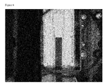
- a distinct dark "streak" caused by unbound gold particulates runs parallel to the long axis of the lateral flow strip, having greatest density towards the centre of the lateral flow strip. The streak can be seen to extend between each of the detection zones which are orthogonal to the long edge of the lateral flow strip.
- Figure 2 back lit / transmitted light
- the "streak" caused by unbound gold is not present.
- Measurement of the transmitted light as compared to the reflected light, effectively reduces the absorbance of unbound particulate conjugates adjacent the detection zone as compared to the absorbance of bound particulate conjugates present in the detection zone.
- the relative and/or absolute difference between (a) the background absorbance of unbound particulate conjugates adjacent the detection or control zones and (b) the signal absorbance of bound particulate conjugates in the detection or control zone is larger in transmitted light mode as compared to reflected light mode.
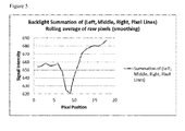
- Figure 5 which shows an intensity profile for transmitted light, illustrates a sharper and larger reduction in detected intensity corresponding to the lateral flow strip as compared to the intensity profile for reflected light ( Figure 4 ). Consequently the transmission mode gives rise to a reduction in the %CV of the signal intensity across the full width of the lateral flow strip, which can be visualized, for example, by a change in pixel intensity across the width of the lateral flow strip when imaged using a camera (such as a digital camera based on a CCD or CMOS sensor).
- a benefit of which is to increase assay sensitivity and reduce limit of detection.
- the absence of the streak in Figure 2 increases the contrast between each detection zone (control zone) and adjacent portions of the lateral flow strip as compared to the reflection mode image of Figure 3 . Accordingly, the back lit configuration is expected to produce heightened sensitivity and reduced background.
- the line profile tool on image pro plus was used to extract pixel intensity information.
- the middle test line i.e., at the middle detection zone was examined.
- Data Chart 1 Analysis of Reflective light Flu A/B Reflective Light Image Analysis Whole Strip Avg (Left, Middle and Right Lines) Background Before Line Peak Avg STD %CV 427 4.075 1.0% Background After Line Peak Avg STD %CV 429 4.690 1.1% Avg total background 428 Line peak Avg (Left, Middle and Right Lines) STD %CV 408 5.217 1.3% Signal Avg Left, Middle and Right Lines (Background minus peak) STD %CV 20 2.1 11%
- Data Chart 2 Analysis of Back light Flu A/B 520nm Back lit Image Analysis Whole Strip Avg (Left, Middle and Right Lines) Background Before Line Peak Avg STD %CV 656 1.181 0.2% Background After Line Peak Avg STD %CV 681 1.892 0.3% Avg total background 669 Line peak Avg (Left, Middle and Right Lines) STD %CV 620 2.203 0.4% Signal Avg Left, Middle and Right Lines
- Example 2 describes experiments to determine if the back lit orientation could reduce background and improve sensitivity with samples such as whole blood, which is a very dark liquid.
- a sample of urine is analyzed for the presence chorionic gonadotrophin (hCG) to establish whether improvement in signal resolution could be achieved by illuminating the assay device from the reverse side.
- hCG chorionic gonadotrophin
- a sample of urine from a pregnant female is obtained. This sample is applied to the reagent zone of an assay device to reconstitute dried particles comprising a gold sol having a mean particle diameter of about 60 nm and an anti-hCG antibody. The sample reconstitutes the dried particles to form a first mixture. The sample mixture then migrates along the assay device toward the detection zone. The hCG-particle complexes accumulate at the detection zone (e.g., are bound) to produce a visible line. Particles within the detection zone accumulate due to formation of immuno-complexes resulting from capture of hCG-particle complexes by an antibody immobilized in the detection zone.
- the assay device When the assay device is illuminated and visualized from the surface on which the detection zone was deposited (that is to say light is reflected off the surface on which the detection zone was present), it is possible to observe a faint smear of unbound particulate conjugates streaming along the assay device (as depicted in Figure 3 ).
- the assay device When the assay device is illuminated from the reverse surface (the opposite surface from which the assay device is observed) such that light is transmitted through the assay device to a detector, a significant enhancement in the contrast of the detection zone occurs.
- Those particulate conjugates which are non-specifically attached to the surface of the assay device in regions of the assay device adjacent to the detection zone i.e., unbound particulate conjugates
- the relative and absolute difference between the absorbance of particulate conjugates bound in the detection zone and the absorbance of particulate conjugates unbound in adjacent areas of the assay device is increased in the transmission mode as compared to the reflection mode. Accordingly, visualization of the assay device using transmission illumination, with acquisition of an optical image from the opposite side to the illuminator, provided an enhanced signal, permitting the detection of lower hCG concentrations than in reflection mode visualization.
Landscapes
- Health & Medical Sciences (AREA)
- Life Sciences & Earth Sciences (AREA)
- Physics & Mathematics (AREA)
- Chemical & Material Sciences (AREA)
- Analytical Chemistry (AREA)
- Biochemistry (AREA)
- General Health & Medical Sciences (AREA)
- General Physics & Mathematics (AREA)
- Immunology (AREA)
- Pathology (AREA)
- Molecular Biology (AREA)
- Investigating Or Analysing Materials By Optical Means (AREA)
Applications Claiming Priority (1)
| Application Number | Priority Date | Filing Date | Title |
|---|---|---|---|
| US201261680067P | 2012-08-06 | 2012-08-06 |
Publications (1)
| Publication Number | Publication Date |
|---|---|
| EP2696193A1 true EP2696193A1 (fr) | 2014-02-12 |
Family
ID=49036424
Family Applications (1)
| Application Number | Title | Priority Date | Filing Date |
|---|---|---|---|
| EP13179218.6A Withdrawn EP2696193A1 (fr) | 2012-08-06 | 2013-08-05 | Systèmes et procédés de détection de dosage |
Country Status (2)
| Country | Link |
|---|---|
| US (1) | US20140038202A1 (fr) |
| EP (1) | EP2696193A1 (fr) |
Cited By (1)
| Publication number | Priority date | Publication date | Assignee | Title |
|---|---|---|---|---|
| US12049494B2 (en) | 2015-06-17 | 2024-07-30 | The Johns Hopkins University | Compositions and methods for detection of malaria biomarkers |
Families Citing this family (4)
| Publication number | Priority date | Publication date | Assignee | Title |
|---|---|---|---|---|
| JP6599721B2 (ja) * | 2015-10-09 | 2019-10-30 | 栄研化学株式会社 | 試験片分析装置及び試験片分析方法 |
| CN115997117A (zh) * | 2020-09-04 | 2023-04-21 | 3M创新有限公司 | 用于生物检测的色谱读取器装置 |
| WO2022049441A1 (fr) * | 2020-09-04 | 2022-03-10 | 3M Innovative Properties Company | Dispositifs de lecture chromatographique pour biodétection |
| US12467911B2 (en) * | 2020-09-04 | 2025-11-11 | 3M Innovative Properties Company | Chromatographic reader devices for biodetection |
Citations (5)
| Publication number | Priority date | Publication date | Assignee | Title |
|---|---|---|---|---|
| US5770389A (en) * | 1993-09-27 | 1998-06-23 | Abbott Laboratories | Apparatus and method for determining the quanity of an analyte in a biological sample by means of transmission photometry |
| US6830934B1 (en) * | 1999-06-15 | 2004-12-14 | Lifescan, Inc. | Microdroplet dispensing for a medical diagnostic device |
| US20050026302A1 (en) * | 2003-07-28 | 2005-02-03 | Suyue Qian | Combining transmittance detection and chromatographic strip techniques providing a simple, easy, sensitive, accurate, fast and inexpensive way to quantitate analytes in biological fluid |
| US20050243321A1 (en) * | 2004-04-30 | 2005-11-03 | Kimberly-Clark Worldwide, Inc. | Transmission-based optical detection systems |
| US7718375B2 (en) | 2002-02-27 | 2010-05-18 | Binax, Inc. | Modification of bioassays for detection of antigens characteristic of bacteria that are causative of ear and respiratory infections to eliminate false positive results caused by nasopharyngeal colonization of children |
-
2013
- 2013-08-05 EP EP13179218.6A patent/EP2696193A1/fr not_active Withdrawn
- 2013-08-06 US US13/960,169 patent/US20140038202A1/en not_active Abandoned
Patent Citations (5)
| Publication number | Priority date | Publication date | Assignee | Title |
|---|---|---|---|---|
| US5770389A (en) * | 1993-09-27 | 1998-06-23 | Abbott Laboratories | Apparatus and method for determining the quanity of an analyte in a biological sample by means of transmission photometry |
| US6830934B1 (en) * | 1999-06-15 | 2004-12-14 | Lifescan, Inc. | Microdroplet dispensing for a medical diagnostic device |
| US7718375B2 (en) | 2002-02-27 | 2010-05-18 | Binax, Inc. | Modification of bioassays for detection of antigens characteristic of bacteria that are causative of ear and respiratory infections to eliminate false positive results caused by nasopharyngeal colonization of children |
| US20050026302A1 (en) * | 2003-07-28 | 2005-02-03 | Suyue Qian | Combining transmittance detection and chromatographic strip techniques providing a simple, easy, sensitive, accurate, fast and inexpensive way to quantitate analytes in biological fluid |
| US20050243321A1 (en) * | 2004-04-30 | 2005-11-03 | Kimberly-Clark Worldwide, Inc. | Transmission-based optical detection systems |
Cited By (1)
| Publication number | Priority date | Publication date | Assignee | Title |
|---|---|---|---|---|
| US12049494B2 (en) | 2015-06-17 | 2024-07-30 | The Johns Hopkins University | Compositions and methods for detection of malaria biomarkers |
Also Published As
| Publication number | Publication date |
|---|---|
| US20140038202A1 (en) | 2014-02-06 |
Similar Documents
| Publication | Publication Date | Title |
|---|---|---|
| US11112338B2 (en) | Dual-image based bioimaging devices and techniques | |
| JP6796175B2 (ja) | 蒸気凝縮液、特に呼気凝縮液を採取し分析する装置及びシステム、並びにそれらの使用方法 | |
| US6274872B1 (en) | Process and device for carrying out quantitative, fluorescence affinity tests | |
| US10753861B2 (en) | Methods for colorimetric analysis | |
| TWI539149B (zh) | An immunochromatographic method, a detection device and a reagent for use in the method | |
| US20090258371A1 (en) | Method of detecting very low levels of analyte within a thin film fluid sample contained in a thin thickness chamber | |
| EP3189331B1 (fr) | Dispositif et procédé d'essais d'immunoanalyse | |
| WO2013096804A2 (fr) | Dispositif de dosage optique ayant un actionnement d'échantillon pneumatique | |
| US20140038202A1 (en) | Assay detection systems and methods | |
| CN212301329U (zh) | 胶体金与荧光材料双显色定量免疫试纸条及其检测装置 | |
| US11668711B2 (en) | Multiplexed diagnostic assay for iron and vitamin A deficiency and methods of use thereof | |
| US20210311038A1 (en) | Indicator-based analysis of a sample | |
| US9255884B2 (en) | Fluorescence strip, fluorescence excitation device and portable fluorescence analysis system with the same | |
| CN105143852A (zh) | 用于检测样本内分析物的器件及方法 | |
| CN115997117A (zh) | 用于生物检测的色谱读取器装置 | |
| WO2003100425A1 (fr) | Dispositif de determination quantitative/lecture de bande de test de procede de chromatographie immunologique | |
| US20070122914A1 (en) | Obtaining measurements of light transmitted through an assay test strip | |
| US20220299431A1 (en) | Assay membrane test region localization | |
| KR101843438B1 (ko) | 진단키트, 이를 이용한 진단장치 및 진단시스템 | |
| JP2011089917A (ja) | 試験片ハウジングおよび濃度測定用イムノクロマトデバイス | |
| CN104181295B (zh) | 一种多线胶体金试纸条定量分析图像处理方法 | |
| CN102782477A (zh) | 使用受控输入光的光学检查 | |
| JP2011214858A (ja) | クロマトグラフ測定方法、並びにそれに用いる不溶性担体および測定装置 | |
| Nguyen et al. | Semi-quantitative Lateral Flow Assay Using a Handheld Device with a Transmissive Readout | |
| CA2260095C (fr) | Procede et dispositif pour mettre en oeuvre des tests quantitatifs d'affinite a fluorescence |
Legal Events
| Date | Code | Title | Description |
|---|---|---|---|
| AK | Designated contracting states |
Kind code of ref document: A1 Designated state(s): AL AT BE BG CH CY CZ DE DK EE ES FI FR GB GR HR HU IE IS IT LI LT LU LV MC MK MT NL NO PL PT RO RS SE SI SK SM TR |
|
| AX | Request for extension of the european patent |
Extension state: BA ME |
|
| PUAI | Public reference made under article 153(3) epc to a published international application that has entered the european phase |
Free format text: ORIGINAL CODE: 0009012 |
|
| STAA | Information on the status of an ep patent application or granted ep patent |
Free format text: STATUS: THE APPLICATION IS DEEMED TO BE WITHDRAWN |
|
| 18D | Application deemed to be withdrawn |
Effective date: 20140813 |