EP2696448A1 - Elektrogerät mit einem Kommunikationsmittel, das auf die Leiterplatte montiert ist - Google Patents
Elektrogerät mit einem Kommunikationsmittel, das auf die Leiterplatte montiert ist Download PDFInfo
- Publication number
- EP2696448A1 EP2696448A1 EP12305982.6A EP12305982A EP2696448A1 EP 2696448 A1 EP2696448 A1 EP 2696448A1 EP 12305982 A EP12305982 A EP 12305982A EP 2696448 A1 EP2696448 A1 EP 2696448A1
- Authority
- EP
- European Patent Office
- Prior art keywords
- electrical
- functional module
- electrical equipment
- printed circuit
- circuit board
- Prior art date
- Legal status (The legal status is an assumption and is not a legal conclusion. Google has not performed a legal analysis and makes no representation as to the accuracy of the status listed.)
- Granted
Links
- 238000004891 communication Methods 0.000 title claims abstract description 44
- 230000005540 biological transmission Effects 0.000 claims abstract description 11
- 230000003993 interaction Effects 0.000 claims description 8
- 238000005259 measurement Methods 0.000 claims description 8
- 230000005611 electricity Effects 0.000 claims description 7
- 238000005516 engineering process Methods 0.000 claims description 3
- 238000009966 trimming Methods 0.000 abstract 1
- 238000012545 processing Methods 0.000 description 23
- 230000006870 function Effects 0.000 description 7
- 238000001514 detection method Methods 0.000 description 2
- 238000000034 method Methods 0.000 description 2
- 235000005921 Cynara humilis Nutrition 0.000 description 1
- 240000002228 Cynara humilis Species 0.000 description 1
- 239000003086 colorant Substances 0.000 description 1
- 230000007246 mechanism Effects 0.000 description 1
- 239000002184 metal Substances 0.000 description 1
- 238000012986 modification Methods 0.000 description 1
- 230000004048 modification Effects 0.000 description 1
- 238000013021 overheating Methods 0.000 description 1
- 230000008569 process Effects 0.000 description 1
- 238000006467 substitution reaction Methods 0.000 description 1
Images





Classifications
-
- H—ELECTRICITY
- H01—ELECTRIC ELEMENTS
- H01R—ELECTRICALLY-CONDUCTIVE CONNECTIONS; STRUCTURAL ASSOCIATIONS OF A PLURALITY OF MUTUALLY-INSULATED ELECTRICAL CONNECTING ELEMENTS; COUPLING DEVICES; CURRENT COLLECTORS
- H01R13/00—Details of coupling devices of the kinds covered by groups H01R12/70 or H01R24/00 - H01R33/00
- H01R13/66—Structural association with built-in electrical component
- H01R13/665—Structural association with built-in electrical component with built-in electronic circuit
- H01R13/6658—Structural association with built-in electrical component with built-in electronic circuit on printed circuit board
-
- H—ELECTRICITY
- H01—ELECTRIC ELEMENTS
- H01R—ELECTRICALLY-CONDUCTIVE CONNECTIONS; STRUCTURAL ASSOCIATIONS OF A PLURALITY OF MUTUALLY-INSULATED ELECTRICAL CONNECTING ELEMENTS; COUPLING DEVICES; CURRENT COLLECTORS
- H01R24/00—Two-part coupling devices, or either of their cooperating parts, characterised by their overall structure
- H01R24/76—Two-part coupling devices, or either of their cooperating parts, characterised by their overall structure with sockets, clips or analogous contacts and secured to apparatus or structure, e.g. to a wall
- H01R24/78—Two-part coupling devices, or either of their cooperating parts, characterised by their overall structure with sockets, clips or analogous contacts and secured to apparatus or structure, e.g. to a wall with additional earth or shield contacts
-
- H—ELECTRICITY
- H01—ELECTRIC ELEMENTS
- H01R—ELECTRICALLY-CONDUCTIVE CONNECTIONS; STRUCTURAL ASSOCIATIONS OF A PLURALITY OF MUTUALLY-INSULATED ELECTRICAL CONNECTING ELEMENTS; COUPLING DEVICES; CURRENT COLLECTORS
- H01R13/00—Details of coupling devices of the kinds covered by groups H01R12/70 or H01R24/00 - H01R33/00
- H01R13/66—Structural association with built-in electrical component
- H01R13/665—Structural association with built-in electrical component with built-in electronic circuit
- H01R13/6683—Structural association with built-in electrical component with built-in electronic circuit with built-in sensor
-
- H—ELECTRICITY
- H01—ELECTRIC ELEMENTS
- H01R—ELECTRICALLY-CONDUCTIVE CONNECTIONS; STRUCTURAL ASSOCIATIONS OF A PLURALITY OF MUTUALLY-INSULATED ELECTRICAL CONNECTING ELEMENTS; COUPLING DEVICES; CURRENT COLLECTORS
- H01R13/00—Details of coupling devices of the kinds covered by groups H01R12/70 or H01R24/00 - H01R33/00
- H01R13/66—Structural association with built-in electrical component
- H01R13/70—Structural association with built-in electrical component with built-in switch
- H01R13/713—Structural association with built-in electrical component with built-in switch the switch being a safety switch
- H01R13/7135—Structural association with built-in electrical component with built-in switch the switch being a safety switch with ground fault protector
-
- H—ELECTRICITY
- H01—ELECTRIC ELEMENTS
- H01R—ELECTRICALLY-CONDUCTIVE CONNECTIONS; STRUCTURAL ASSOCIATIONS OF A PLURALITY OF MUTUALLY-INSULATED ELECTRICAL CONNECTING ELEMENTS; COUPLING DEVICES; CURRENT COLLECTORS
- H01R13/00—Details of coupling devices of the kinds covered by groups H01R12/70 or H01R24/00 - H01R33/00
- H01R13/66—Structural association with built-in electrical component
- H01R13/717—Structural association with built-in electrical component with built-in light source
- H01R13/7175—Light emitting diodes (LEDs)
-
- H—ELECTRICITY
- H01—ELECTRIC ELEMENTS
- H01R—ELECTRICALLY-CONDUCTIVE CONNECTIONS; STRUCTURAL ASSOCIATIONS OF A PLURALITY OF MUTUALLY-INSULATED ELECTRICAL CONNECTING ELEMENTS; COUPLING DEVICES; CURRENT COLLECTORS
- H01R2103/00—Two poles
Definitions
- the present invention relates to the field of electrical appliances for the building and relates to a particular electrical equipment.
- electrical equipment In addition to their connection with an electrical power network, electrical equipment, plug socket or switch socket, sometimes have functional interactions with an electrical information network. It may for example be a remote controlled electrical outlet, a switch sending a command, or an electrical equipment connected to an information network to account for its operation. Electrical equipment therefore sometimes combines electrics used for communication networks with electrics used for power networks.
- DE 10 2005 025541 discloses an apparatus of this type, in the form of a base provided with means for measuring electricity, and capable of sending a signal wirelessly when a certain electrical situation arises.
- WO 96/35133 discloses an electrical apparatus combining a three-phase power current transmission and an information transmission to a suitable electrical plug.
- the disadvantage of such a device is that its size is greater and it is not possible to mount this equipment in a standard wall mounting box, especially for a recessed mounting in a wall.
- the present invention aims to overcome at least a part and preferably all these disadvantages, and therefore aims to provide electrical equipment capable of communicating with an information network, having a small footprint.
- the subject of the invention is an electrical apparatus for projecting or recessed mounting by means of a box, comprising a communication means for exchanging information with other elements such as with a control unit. control, and also comprising an electrical functional module.
- the electrical equipment is characterized in that it comprises a printed circuit board, called a communication card, carrying the means communicating and positioned against the electrical functional module so as to come between the latter and the box.
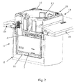
- the invention therefore relates to an electrical apparatus 1, for a surface mounting or recessed using a box 2, comprising a communication means 3 for exchanging information with other elements as with a central control device, and also comprising an electrical functional module 4.
- the electrical equipment 1 may for example be an electrical switch or an electrical transmission base, and the electrical functional module 4 can then be a module electrical connection of pins for a base or an electrical function module for switching a contact for a switch.
- the electrical functional module 4 groups the primary electrical functions of the electrical equipment 1 and therefore deals with power currents. It is normally placed in a standard size box 2 of common dimensions defining a template for said electrical equipment 1, and especially a box 2 for a flush mounting, in which case the congestion constraint is even more difficult to meet.
- the electrical functional module 4 is not limited to a home automation control module, for example, but includes the elements necessary for the flow of power electricity, for example for a power supply, in the case of a base wall, or the opening / closing of an electrical circuit, in the case of an electrical switch.
- the voltage and working current of the electrical functional module are therefore for example approximately 230 volts and 10 amperes respectively.
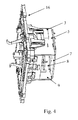
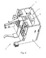
- the electrical equipment 1 comprises a printed circuit board, called communication card 5, carrying the communication means 3 and positioned against the electrical functional module 4 so as to come between the latter and the box 2, in particular a communication card 5 placed laterally along one side of the electrical functional module 4, perpendicular to the wall in which the electrical equipment 1 is normally installed.
- communication card 5 a printed circuit board, called communication card 5, carrying the communication means 3 and positioned against the electrical functional module 4 so as to come between the latter and the box 2, in particular a communication card 5 placed laterally along one side of the electrical functional module 4, perpendicular to the wall in which the electrical equipment 1 is normally installed.
- the electrical equipment 1 thus has a first printed circuit board, advantageously placed laterally on the side of the electrical functional module 4, and on which is placed the communication means 3.
- the latter thus takes the form of a component arranged to be mounted on a printed circuit board, in particular an electronic component. It is of such dimensions that the electrical equipment 1 complies with the jig of the box 2 and the electrical equipment 1 can be mounted in the box 2, in particular a box 2 for flush mounting.
- the electrical apparatus 1 therefore simultaneously processes currents intended for power, circulating within the electrical functional module 4, and currents for a communication network, circulating in the printed circuit board or in one of those described below. .
- the electrical apparatus 1 also comprises a processing unit, preferably in the form of a microprocessor, capable of interacting with the communication means 3, and of using it to transmit or receive information.
- This microprocessor can be mounted on the communication board 5 or on any other possible printed circuit boards described below.
- This processing unit thus controls at least part or all of the functions of the electrical equipment 1.
- the electrical functional module 4 is an electrical energy transmission module, so that the electrical equipment 1 is arranged to form an electrical base, the latter comprising means 6 for breaking the electrical transmission, in particular in the form of at least one relay, at least one TRIAC, or at least one electromagnetic actuator.
- the cutoff means 6 can therefore be electronic, as is the case for a TRIAC, or electromagnetic, as is the case for a combination of a magnetic core and a coil.
- the breaking means 6 can be controlled by the processing unit described above.
- the breaking means 6 are controllable on the basis of information received by the communication means 3, in particular on the basis of a command sent from a central control apparatus.
- the control can also be done on the basis of a local detection, at the level of the electrical equipment 1.
- the electrical equipment 1 may have measuring means, which can provide information to the processing unit, in particular as to the current, the temperature, or the voltage, which can then switch the breaking means 6.
- the information is preferably received by the communication means 3, processed by the processing unit, which then controls the switching state of the breaking means 6.
- the electrical equipment 1 in question can therefore incorporate a protection function: the triggering of the breaking means 6 is controlled, in particular by the processing unit, when a situation deemed dangerous occurs or if a command of this type is received by the communication means 3.
- the processing unit is therefore able to control the switching of the breaking means 6.
- the cutoff means 6 can also switch unmanned, as is the case for example if it is an electromagnetic operation and the movement of an actuator is generated by the magnetic field caused by overcurrent. In this case, the switching is done without applying logic of processing information.
- the electrical equipment 1 comprises a printed circuit board, called a cut-off card 7, carrying the cut-off means 6 and positioned against the electrical functional module 4 so as to come between the latter and the box 2.
- the cut-off card 7 can in particular be placed at the rear of the electrical functional module 4, parallel to the wall in which the electrical equipment 1 is normally installed. This feature is particularly compatible with the cases where the breaking means 6 are electronic. In these cases, either the cut card 7 itself carries the processing unit, or it is connected to another printed circuit board on which said unit is mounted. The processing unit can then easily control the state of the cutoff means 6 since they are both connected, either on two different printed circuit boards but which communicate between it, or on the same card.
- the electrical equipment 1 comprises means able to detect an electrical imbalance caused by a leakage to the ground, and to stop the electrical transmission, these means including a torus 8 and can act on the means
- the electrical imbalance itself creates the switching of the breaking means 6, then generally in the form of moving contacts moved under a force generated by said imbalance. This principle is widely used in differential circuit breaker type applications.
- the imbalance can be an information sent to said processing unit, the latter consequently controlling the triggering of the breaking means which are, in this case, case, necessarily controllable.
- the electrical equipment comprises a printed circuit board, called measuring board 9, carrying means for measuring the parameters of the electricity flowing in the electrical equipment 1, positioned against the electrical functional module 4 so as to come between the latter and the box 2. It may especially be a means for measuring temperature, current or voltage , said measurement card 9 being in particular placed laterally along one side of the electrical functional module 4, perpendicular to the wall in which the electrical equipment 1 is normally installed.
- These measuring means therefore provide information necessary for the processing unit, via the measurement card 9 which is identical or connected to the printed circuit board on which said processing unit is mounted.
- the measured parameters are communicated to the processing unit, which can decide to act on the devices.
- breaking means 6 for stopping the flow of electrical energy.
- the processing unit which therefore communicates through at least one printed circuit board with the communication means, and, if necessary, the measuring means, can therefore take into account various information for controlling the switching state of the devices. breaking means 6.
- the communication means 3 communicates wirelessly, in particular with the Wifi technique and / or the KNX language. It then consists of an element both transmitter and receiver, fixed on the communication card 5. It is then necessary to position the antenna receiving and transmitting signal so as to avoid interference.
- the electrical equipment 1 comprises an antenna for the communication means 3, placed in the front part of a trim 12 of the electrical equipment 1 through which the interaction with the Electric functional module 4 is possible.
- the communication can be done with or without wire, the communication means 3 being naturally adapted to the selected communication mode.
- the technology of power line currents, CPL for example.
- the connection can be done by Wifi, for example.
- Communication can use KNX formalism, whether with or without wires.
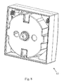
- the electrical functional module 4 is covered with a shell 11 of dimensions compatible with its housing in the box 2, the at least one printed circuit board, namely the or a communication card 5 or / and the or a cut card 7 or / and the or a measurement card 9, being housed or housed between the electrical functional module 4 and said shell 11, in particular a shell 11 consisting of perpendicular planar walls, forming a parallelepipedal shell 11 , the or hubcap 12 being for example fixed to said shell 11 by snapping.
- the shell 11 thus fully protects the electrical functional module 4 and the at least one printed circuit board which are placed around it, namely the communication card 5, and / or the cut card 7 or / and the measurement card 9.
- the shell 11 can thus be directly fixed, in particular by snapping, to a flat support 16, plastic or metal insulated by a layer of plastic, this support 16 being intended to be fixed to the box 2.
- a preassembled element can be formed comprising at least the shell 11, inside which the electrical functional module 4 is fixed by snapping, and, between said module and the walls of this shell 11, at least one printed circuit board as described herein. -above. This pre-assembled element can then be fixed, in particular by snapping, into the support 16.
- the shell 11 is provided with orifices 17 suitable for the wired connection between the electrical functional module and the electrical power network, and thus for passing electrical cables to the electrical functional module 4.
- the electrical functional module 4 is therefore bordered, with the exception of an interaction zone situated generally at the front, of several printed circuit boards, placed on the side, for example for the communication card 5 and the measurement card 9, and at the back, that is to say on the opposite side to the interaction zone with the user, for the cut card 7.
- the electrical equipment 1 further comprises a hubcap 12, through which a user can interact with the electrical functional module 4, said hubcap 12 communicating electrically with at least one side printed circuit board positioned against the electrical functional module 4 so as to come between the latter and the box 2, along one side of the module electrical functional 4, in particular the communication card 5 and / or the or measurement card 9.
- the hubcap 12 may in particular comprise a well 13 for receiving an electrical plug or a joystick for actuating a functional module electrical switching.
- the hubcap 12 in addition to its primary function of interaction with the electrical functional module 4, is therefore provided with functions requiring electricity and using an electrical flow of information with the processing unit and therefore an electrical communication, at the less at voltage levels for information flow.
- these functions can be a display, using a diode that must be controlled electrically, or touch control means, which must send an electrical signal, or means information exchange with the processor.
- the hubcap 12 therefore comprises means requiring a flow of electricity, preferably mounted on at least one facade printed circuit board 20 which it comprises and which can be plugged into a lateral printed circuit board extending over a sides of the electrical functional module 4, and which is thus placed in electrical communication at least with the processing unit.
- This electrical communication is thus carried out via a side printed circuit board placed on one side of the electrical functional module 4 and to which the hubcap 12 can be connected, via a facade printed circuit board 20.
- this side printed circuit board can be the communication card 5, the measurement card 9 or other. It therefore extends sufficiently ahead of the electrical equipment 1 to arrive at the hubcap 12.
- This side card is connected to the hubcap 12 by a set of base and plug compatible with printed circuit technology, in particular at least one terminal 19 mounted on the lateral printed circuit board, and plugs mounted in the hubcap 12,
- the trim 12 is connected to the at least one lateral printed circuit board by means of terminals 19 and fitted connection plugs, a part, at the level of the hubcap 12, and, secondly, at the level of said card, to make a connection by racking.
- the hubcap 12 is provided with display means 14, of the diode type. These can be diodes of different colors, mounted in the hubcap 12, on a facade circuit board 20 carrying the connection plugs with a side printed circuit board placed on one side of the electrical functional module 4. Each of these diodes can be associated with a mode of operation of the electrical equipment 1, which allows in particular to account for any electrical overload of a base, or close to overload regimes.
- the hubcap 12 is provided with tactile control means 15, such as buttons or capacitive areas.
- the touch control means 15 may be pushbuttons mounted on a printed circuit board placed in the hubcap 12.
- the hubcap 12 is provided with a USB port 18.
- This USB port 18 is mounted on a facade printed circuit board 20 that includes the hubcap 12 and can be electrically connected, directly or through at least one side printed circuit board, to the processing unit.
- This USB port 18 emerges naturally outside the electrical equipment 1. With this USB port 18, it is thus possible to configure the processing unit, but also to extract a set of data relating to the operation of the device. electrical equipment 1 that would have been stored in a memory of the electrical equipment 1. It is also possible to consider using this USB port for an electric charging of a battery of another device, such as mobile phone, digital camera, etc.
- the hubcap 12 is provided with a transponder detector, in particular an RFID detector.
- the transponder detector is mounted on a printed circuit board, placed in the hubcap 12, and which can be plugged into a side printed circuit board which extends on one side of the electrical functional module 4.
- transponder detector is thus connected, directly or via a side printed circuit board, to the processing unit, itself able to control the breaking means 6 of the transmission of electrical energy, it is It is possible to operate the electrical equipment 1 only if a particular transponder has been detected in the immediate environment of the hubcap 12.
- the electrical equipment 1 so that the transponder detector informs processing unit in case of detection, then that the communication means 3 allows a connection to a database to identify the transponder as well as a set of information associated therewith, such as a subscription, power supply conditions, etc.
- the side printed circuit board to which the hubcap 12 is connected in cases where it does not itself carry the processing unit, is electrically connected to the printed circuit board on which said unit is mounted.
- the electronic components of an electrical apparatus are supplied with electricity by means of the electrical power network to which said apparatus is wired.
- one of the printed circuit boards is wired to the electrical network, where the other possible cards are then electrically connected or connected.
- the power supply is made from the printed circuit board located at the rear of the electrical functional module 4, this printed circuit board optionally supplying downstream at least one other printed circuit board, then placed laterally, c that is to say on the side of the electrical functional module 4.
Landscapes
- Engineering & Computer Science (AREA)
- Microelectronics & Electronic Packaging (AREA)
- Arrangements For Transmission Of Measured Signals (AREA)
- Casings For Electric Apparatus (AREA)
Priority Applications (1)
| Application Number | Priority Date | Filing Date | Title |
|---|---|---|---|
| EP12305982.6A EP2696448B1 (de) | 2012-08-08 | 2012-08-08 | Elektrogerät mit einem Kommunikationsmittel, das auf die Leiterplatte montiert ist |
Applications Claiming Priority (1)
| Application Number | Priority Date | Filing Date | Title |
|---|---|---|---|
| EP12305982.6A EP2696448B1 (de) | 2012-08-08 | 2012-08-08 | Elektrogerät mit einem Kommunikationsmittel, das auf die Leiterplatte montiert ist |
Publications (2)
| Publication Number | Publication Date |
|---|---|
| EP2696448A1 true EP2696448A1 (de) | 2014-02-12 |
| EP2696448B1 EP2696448B1 (de) | 2018-07-18 |
Family
ID=46875705
Family Applications (1)
| Application Number | Title | Priority Date | Filing Date |
|---|---|---|---|
| EP12305982.6A Not-in-force EP2696448B1 (de) | 2012-08-08 | 2012-08-08 | Elektrogerät mit einem Kommunikationsmittel, das auf die Leiterplatte montiert ist |
Country Status (1)
| Country | Link |
|---|---|
| EP (1) | EP2696448B1 (de) |
Cited By (6)
| Publication number | Priority date | Publication date | Assignee | Title |
|---|---|---|---|---|
| WO2015181006A1 (de) * | 2014-05-27 | 2015-12-03 | Endress+Hauser Flowtec Ag | Erdungsvorrichtung |
| CN105609925A (zh) * | 2016-02-29 | 2016-05-25 | 国网新疆电力公司昌吉供电公司 | 中压开关柜室外天线 |
| BE1022962B1 (nl) * | 2015-04-21 | 2016-10-24 | Niko, Nv | Contactdoossamenstel voor inbouw in een wand |
| FR3040244A1 (fr) * | 2015-08-20 | 2017-02-24 | Legrand France | Prise electrique comprenant un circuit imprime |
| FR3057711A1 (fr) * | 2016-10-18 | 2018-04-20 | Legrand France | Prise electrique comprenant une piece monobloc de support et de reception d'alveoles et procede d'assemblage d'une telle prise electrique |
| EP3236540A4 (de) * | 2016-06-12 | 2018-08-01 | Guangzhou Leishen Electric Manufacturing Co., Ltd. | Wandsteckdose mit usb-ladevorrichtung |
Families Citing this family (1)
| Publication number | Priority date | Publication date | Assignee | Title |
|---|---|---|---|---|
| DE102021105047B3 (de) * | 2021-03-03 | 2022-01-13 | Albrecht Jung Gmbh & Co. Kg | Elektrisches/elektronisches Gerät sowie Verfahren zur Montage desselben |
Citations (10)
| Publication number | Priority date | Publication date | Assignee | Title |
|---|---|---|---|---|
| WO1996035133A1 (de) | 1995-05-06 | 1996-11-07 | Gebr. Merten Gmbh & Co. Kg | Elektrische steckvorrichtung |
| DE202006006105U1 (de) * | 2006-04-15 | 2006-08-10 | Gira Giersiepen Gmbh & Co. Kg | Elektro-Installationsgerät sowie zugehörige Zentralabdeckung |
| US20060185876A1 (en) * | 2005-02-18 | 2006-08-24 | Soffer Aviv | Insertable wall mounted computing apparatus |
| DE102005025541A1 (de) | 2005-06-03 | 2006-12-07 | Abb Patent Gmbh | Steckdose und Anzeigesystem eines Gebäudes mit mehreren Steckdosen |
| US20070086127A1 (en) * | 2005-02-25 | 2007-04-19 | Huadao Huang | Ground fault circuit interrupter containing a dual-function test button |
| DE102007063592A1 (de) * | 2007-12-21 | 2009-07-02 | Merten Gmbh & Co. Kg | Kontaktelement |
| WO2010110777A1 (en) * | 2009-03-24 | 2010-09-30 | Ever Win International Corporation | In-wall multi-voltage ac/dc delivery system |
| EP2315318A1 (de) * | 2009-10-24 | 2011-04-27 | Berker GmbH & Co. KG | Elektrische Schutzkontaktsteckdose |
| WO2012010170A1 (en) * | 2010-07-22 | 2012-01-26 | Barfred Niels G | An intelligent switch |
| US20120024966A1 (en) * | 2011-10-07 | 2012-02-02 | Kurt Vanderwel | Selectively concealable indicator systems and assemblies |
Family Cites Families (2)
| Publication number | Priority date | Publication date | Assignee | Title |
|---|---|---|---|---|
| US20060185878A1 (en) * | 2005-02-18 | 2006-08-24 | Aviv Soffer | Wall mounted housing for insertable computing apparatus |
| DE102009050597A1 (de) * | 2009-10-24 | 2011-05-12 | Berker Gmbh & Co. Kg | Elektrische Schutzkontaktsteckdose |
-
2012
- 2012-08-08 EP EP12305982.6A patent/EP2696448B1/de not_active Not-in-force
Patent Citations (10)
| Publication number | Priority date | Publication date | Assignee | Title |
|---|---|---|---|---|
| WO1996035133A1 (de) | 1995-05-06 | 1996-11-07 | Gebr. Merten Gmbh & Co. Kg | Elektrische steckvorrichtung |
| US20060185876A1 (en) * | 2005-02-18 | 2006-08-24 | Soffer Aviv | Insertable wall mounted computing apparatus |
| US20070086127A1 (en) * | 2005-02-25 | 2007-04-19 | Huadao Huang | Ground fault circuit interrupter containing a dual-function test button |
| DE102005025541A1 (de) | 2005-06-03 | 2006-12-07 | Abb Patent Gmbh | Steckdose und Anzeigesystem eines Gebäudes mit mehreren Steckdosen |
| DE202006006105U1 (de) * | 2006-04-15 | 2006-08-10 | Gira Giersiepen Gmbh & Co. Kg | Elektro-Installationsgerät sowie zugehörige Zentralabdeckung |
| DE102007063592A1 (de) * | 2007-12-21 | 2009-07-02 | Merten Gmbh & Co. Kg | Kontaktelement |
| WO2010110777A1 (en) * | 2009-03-24 | 2010-09-30 | Ever Win International Corporation | In-wall multi-voltage ac/dc delivery system |
| EP2315318A1 (de) * | 2009-10-24 | 2011-04-27 | Berker GmbH & Co. KG | Elektrische Schutzkontaktsteckdose |
| WO2012010170A1 (en) * | 2010-07-22 | 2012-01-26 | Barfred Niels G | An intelligent switch |
| US20120024966A1 (en) * | 2011-10-07 | 2012-02-02 | Kurt Vanderwel | Selectively concealable indicator systems and assemblies |
Cited By (8)
| Publication number | Priority date | Publication date | Assignee | Title |
|---|---|---|---|---|
| WO2015181006A1 (de) * | 2014-05-27 | 2015-12-03 | Endress+Hauser Flowtec Ag | Erdungsvorrichtung |
| BE1022962B1 (nl) * | 2015-04-21 | 2016-10-24 | Niko, Nv | Contactdoossamenstel voor inbouw in een wand |
| EP3086418A1 (de) * | 2015-04-21 | 2016-10-26 | Niko NV | Fassungsanordnung zum oberflächeneinbau in einer wand |
| FR3040244A1 (fr) * | 2015-08-20 | 2017-02-24 | Legrand France | Prise electrique comprenant un circuit imprime |
| CN105609925A (zh) * | 2016-02-29 | 2016-05-25 | 国网新疆电力公司昌吉供电公司 | 中压开关柜室外天线 |
| EP3236540A4 (de) * | 2016-06-12 | 2018-08-01 | Guangzhou Leishen Electric Manufacturing Co., Ltd. | Wandsteckdose mit usb-ladevorrichtung |
| FR3057711A1 (fr) * | 2016-10-18 | 2018-04-20 | Legrand France | Prise electrique comprenant une piece monobloc de support et de reception d'alveoles et procede d'assemblage d'une telle prise electrique |
| EP3312948A1 (de) * | 2016-10-18 | 2018-04-25 | Legrand France | Elektrische steckdose, die ein monoblockteil zur halterung und aufnahme von höckereinsätzen umfasst, und verfahren zum zusammenbau einer solchen elektrischen steckdose |
Also Published As
| Publication number | Publication date |
|---|---|
| EP2696448B1 (de) | 2018-07-18 |
Similar Documents
| Publication | Publication Date | Title |
|---|---|---|
| EP2696448B1 (de) | Elektrogerät mit einem Kommunikationsmittel, das auf die Leiterplatte montiert ist | |
| EP3256983B1 (de) | Elektrisches gerät, system mit solch einem gerät und in einem solchen system ausgeführtes verfahren | |
| US10256862B2 (en) | System and method for displaying device-specific information for a smart device | |
| EP2672605B1 (de) | Ladevorrichtung für eine Batterie in einem Elektrofahrzeug oder Elektro-Hybridfahrzeug | |
| EP0923185A1 (de) | Elektrische Unterbrechungsvorrichtung mit einem Kommunikationsmodul | |
| EP3179582A1 (de) | Kommunikationsschnittstelle für einen herausnehmbaren einschub eines schaltschranks und schaltschrank, der eine solche kommunikationsschnittstelle umfasst | |
| EP1318537B1 (de) | Einheit von elektrischen Vorrichtungen zur Steuerung von Leistungsvorrichtungen | |
| JP2010277718A (ja) | 電気自動車用充電装置 | |
| US9281635B2 (en) | Connector and connector bar | |
| EP3512057B1 (de) | Elektrisches gerät, das drahtlos kommuniziert, und elektrischer schaltschrank, der ein solches elektrisches gerät umfasst | |
| EP3050176B1 (de) | Elektrische vorrichtung mit einer steckdose mit einem magneten und einer abschaltung, und elektrische baugruppe damit | |
| WO2019122187A1 (fr) | Appareil auxiliaire pour appareillage de protection électrique | |
| WO2012032066A1 (fr) | Boitier d'alimentation pour appareil de communication | |
| EP0420058B1 (de) | Elektrisches Sicherheitssteckdosensystem | |
| EP1117115B1 (de) | Differentialschutzvorrichtung, insbesondere Differentialschutzschalter | |
| KR102656474B1 (ko) | 급속 및 완속 충전 일체형 사용자인증 이동형 충전장치 | |
| EP3086418B1 (de) | Zentralelement für fassungsanordnung zum oberflächeneinbau in einer wand | |
| EP3182434B1 (de) | Vorrichtung zur steuerung einer auf einen steuerungskreislauf anpassbaren elektrischen ladung | |
| EP3336874B1 (de) | Trennschalter | |
| FR2949280A1 (fr) | Ouverture et fermeture d'un circuit electrique via reconnaissance rfid | |
| WO2019011406A1 (fr) | Appareillage electrique et module fonctionnel additionnel associe | |
| EP1834366B1 (de) | Batteriebetriebene einrichtung für einen stromzähler und stromzähler | |
| EP4459884A1 (de) | Durch nahfeldkommunikation konfigurierbare elektrische vorrichtung und verfahren | |
| FR3063175A1 (fr) | Appareil auxiliaire pour appareillage de protection electrique et ensemble electrique comprenant ledit appareil auxiliaire | |
| FR2990785A1 (fr) | Systeme d'echange de donnees |
Legal Events
| Date | Code | Title | Description |
|---|---|---|---|
| AK | Designated contracting states |
Kind code of ref document: A1 Designated state(s): AL AT BE BG CH CY CZ DE DK EE ES FI FR GB GR HR HU IE IS IT LI LT LU LV MC MK MT NL NO PL PT RO RS SE SI SK SM TR |
|
| AX | Request for extension of the european patent |
Extension state: BA ME |
|
| PUAI | Public reference made under article 153(3) epc to a published international application that has entered the european phase |
Free format text: ORIGINAL CODE: 0009012 |
|
| RIN1 | Information on inventor provided before grant (corrected) |
Inventor name: MOLLITOR, JENS Inventor name: JEUNESSE, PIERRE Inventor name: POLI, MASSIMILIANO Inventor name: ROIATTI, JEAN-MARIE |
|
| 17P | Request for examination filed |
Effective date: 20140807 |
|
| RBV | Designated contracting states (corrected) |
Designated state(s): AL AT BE BG CH CY CZ DE DK EE ES FI FR GB GR HR HU IE IS IT LI LT LU LV MC MK MT NL NO PL PT RO RS SE SI SK SM TR |
|
| 17Q | First examination report despatched |
Effective date: 20150430 |
|
| GRAP | Despatch of communication of intention to grant a patent |
Free format text: ORIGINAL CODE: EPIDOSNIGR1 |
|
| RIC1 | Information provided on ipc code assigned before grant |
Ipc: H01R 13/717 20060101ALN20180206BHEP Ipc: H01R 103/00 20060101ALN20180206BHEP Ipc: H01R 13/66 20060101AFI20180206BHEP Ipc: H01R 24/78 20110101ALI20180206BHEP Ipc: H01R 13/713 20060101ALN20180206BHEP |
|
| RIC1 | Information provided on ipc code assigned before grant |
Ipc: H01R 13/66 20060101AFI20180212BHEP Ipc: H01R 13/717 20060101ALN20180212BHEP Ipc: H01R 103/00 20060101ALN20180212BHEP Ipc: H01R 13/713 20060101ALN20180212BHEP Ipc: H01R 24/78 20110101ALI20180212BHEP |
|
| INTG | Intention to grant announced |
Effective date: 20180227 |
|
| GRAJ | Information related to disapproval of communication of intention to grant by the applicant or resumption of examination proceedings by the epo deleted |
Free format text: ORIGINAL CODE: EPIDOSDIGR1 |
|
| GRAR | Information related to intention to grant a patent recorded |
Free format text: ORIGINAL CODE: EPIDOSNIGR71 |
|
| GRAS | Grant fee paid |
Free format text: ORIGINAL CODE: EPIDOSNIGR3 |
|
| GRAA | (expected) grant |
Free format text: ORIGINAL CODE: 0009210 |
|
| INTC | Intention to grant announced (deleted) | ||
| RIC1 | Information provided on ipc code assigned before grant |
Ipc: H01R 103/00 20060101ALN20180604BHEP Ipc: H01R 13/713 20060101ALN20180604BHEP Ipc: H01R 24/78 20110101ALI20180604BHEP Ipc: H01R 13/717 20060101ALN20180604BHEP Ipc: H01R 13/66 20060101AFI20180604BHEP |
|
| AK | Designated contracting states |
Kind code of ref document: B1 Designated state(s): AL AT BE BG CH CY CZ DE DK EE ES FI FR GB GR HR HU IE IS IT LI LT LU LV MC MK MT NL NO PL PT RO RS SE SI SK SM TR |
|
| INTG | Intention to grant announced |
Effective date: 20180612 |
|
| REG | Reference to a national code |
Ref country code: GB Ref legal event code: FG4D Free format text: NOT ENGLISH |
|
| REG | Reference to a national code |
Ref country code: CH Ref legal event code: EP |
|
| REG | Reference to a national code |
Ref country code: IE Ref legal event code: FG4D Free format text: LANGUAGE OF EP DOCUMENT: FRENCH |
|
| REG | Reference to a national code |
Ref country code: AT Ref legal event code: REF Ref document number: 1020371 Country of ref document: AT Kind code of ref document: T Effective date: 20180815 |
|
| REG | Reference to a national code |
Ref country code: DE Ref legal event code: R096 Ref document number: 602012048563 Country of ref document: DE |
|
| REG | Reference to a national code |
Ref country code: NL Ref legal event code: MP Effective date: 20180718 |
|
| REG | Reference to a national code |
Ref country code: LT Ref legal event code: MG4D |
|
| REG | Reference to a national code |
Ref country code: AT Ref legal event code: MK05 Ref document number: 1020371 Country of ref document: AT Kind code of ref document: T Effective date: 20180718 |
|
| PG25 | Lapsed in a contracting state [announced via postgrant information from national office to epo] |
Ref country code: NL Free format text: LAPSE BECAUSE OF FAILURE TO SUBMIT A TRANSLATION OF THE DESCRIPTION OR TO PAY THE FEE WITHIN THE PRESCRIBED TIME-LIMIT Effective date: 20180718 |
|
| PG25 | Lapsed in a contracting state [announced via postgrant information from national office to epo] |
Ref country code: FI Free format text: LAPSE BECAUSE OF FAILURE TO SUBMIT A TRANSLATION OF THE DESCRIPTION OR TO PAY THE FEE WITHIN THE PRESCRIBED TIME-LIMIT Effective date: 20180718 Ref country code: PL Free format text: LAPSE BECAUSE OF FAILURE TO SUBMIT A TRANSLATION OF THE DESCRIPTION OR TO PAY THE FEE WITHIN THE PRESCRIBED TIME-LIMIT Effective date: 20180718 Ref country code: BG Free format text: LAPSE BECAUSE OF FAILURE TO SUBMIT A TRANSLATION OF THE DESCRIPTION OR TO PAY THE FEE WITHIN THE PRESCRIBED TIME-LIMIT Effective date: 20181018 Ref country code: GR Free format text: LAPSE BECAUSE OF FAILURE TO SUBMIT A TRANSLATION OF THE DESCRIPTION OR TO PAY THE FEE WITHIN THE PRESCRIBED TIME-LIMIT Effective date: 20181019 Ref country code: NO Free format text: LAPSE BECAUSE OF FAILURE TO SUBMIT A TRANSLATION OF THE DESCRIPTION OR TO PAY THE FEE WITHIN THE PRESCRIBED TIME-LIMIT Effective date: 20181018 Ref country code: SE Free format text: LAPSE BECAUSE OF FAILURE TO SUBMIT A TRANSLATION OF THE DESCRIPTION OR TO PAY THE FEE WITHIN THE PRESCRIBED TIME-LIMIT Effective date: 20180718 Ref country code: RS Free format text: LAPSE BECAUSE OF FAILURE TO SUBMIT A TRANSLATION OF THE DESCRIPTION OR TO PAY THE FEE WITHIN THE PRESCRIBED TIME-LIMIT Effective date: 20180718 Ref country code: LT Free format text: LAPSE BECAUSE OF FAILURE TO SUBMIT A TRANSLATION OF THE DESCRIPTION OR TO PAY THE FEE WITHIN THE PRESCRIBED TIME-LIMIT Effective date: 20180718 Ref country code: IS Free format text: LAPSE BECAUSE OF FAILURE TO SUBMIT A TRANSLATION OF THE DESCRIPTION OR TO PAY THE FEE WITHIN THE PRESCRIBED TIME-LIMIT Effective date: 20181118 Ref country code: AT Free format text: LAPSE BECAUSE OF FAILURE TO SUBMIT A TRANSLATION OF THE DESCRIPTION OR TO PAY THE FEE WITHIN THE PRESCRIBED TIME-LIMIT Effective date: 20180718 |
|
| PG25 | Lapsed in a contracting state [announced via postgrant information from national office to epo] |
Ref country code: HR Free format text: LAPSE BECAUSE OF FAILURE TO SUBMIT A TRANSLATION OF THE DESCRIPTION OR TO PAY THE FEE WITHIN THE PRESCRIBED TIME-LIMIT Effective date: 20180718 Ref country code: AL Free format text: LAPSE BECAUSE OF FAILURE TO SUBMIT A TRANSLATION OF THE DESCRIPTION OR TO PAY THE FEE WITHIN THE PRESCRIBED TIME-LIMIT Effective date: 20180718 Ref country code: LV Free format text: LAPSE BECAUSE OF FAILURE TO SUBMIT A TRANSLATION OF THE DESCRIPTION OR TO PAY THE FEE WITHIN THE PRESCRIBED TIME-LIMIT Effective date: 20180718 |
|
| REG | Reference to a national code |
Ref country code: DE Ref legal event code: R119 Ref document number: 602012048563 Country of ref document: DE |
|
| REG | Reference to a national code |
Ref country code: CH Ref legal event code: PL |
|
| PG25 | Lapsed in a contracting state [announced via postgrant information from national office to epo] |
Ref country code: ES Free format text: LAPSE BECAUSE OF FAILURE TO SUBMIT A TRANSLATION OF THE DESCRIPTION OR TO PAY THE FEE WITHIN THE PRESCRIBED TIME-LIMIT Effective date: 20180718 Ref country code: CH Free format text: LAPSE BECAUSE OF NON-PAYMENT OF DUE FEES Effective date: 20180831 Ref country code: LU Free format text: LAPSE BECAUSE OF NON-PAYMENT OF DUE FEES Effective date: 20180808 Ref country code: EE Free format text: LAPSE BECAUSE OF FAILURE TO SUBMIT A TRANSLATION OF THE DESCRIPTION OR TO PAY THE FEE WITHIN THE PRESCRIBED TIME-LIMIT Effective date: 20180718 Ref country code: CZ Free format text: LAPSE BECAUSE OF FAILURE TO SUBMIT A TRANSLATION OF THE DESCRIPTION OR TO PAY THE FEE WITHIN THE PRESCRIBED TIME-LIMIT Effective date: 20180718 Ref country code: RO Free format text: LAPSE BECAUSE OF FAILURE TO SUBMIT A TRANSLATION OF THE DESCRIPTION OR TO PAY THE FEE WITHIN THE PRESCRIBED TIME-LIMIT Effective date: 20180718 Ref country code: LI Free format text: LAPSE BECAUSE OF NON-PAYMENT OF DUE FEES Effective date: 20180831 Ref country code: IT Free format text: LAPSE BECAUSE OF FAILURE TO SUBMIT A TRANSLATION OF THE DESCRIPTION OR TO PAY THE FEE WITHIN THE PRESCRIBED TIME-LIMIT Effective date: 20180718 Ref country code: MC Free format text: LAPSE BECAUSE OF FAILURE TO SUBMIT A TRANSLATION OF THE DESCRIPTION OR TO PAY THE FEE WITHIN THE PRESCRIBED TIME-LIMIT Effective date: 20180718 |
|
| REG | Reference to a national code |
Ref country code: BE Ref legal event code: MM Effective date: 20180831 |
|
| PLBE | No opposition filed within time limit |
Free format text: ORIGINAL CODE: 0009261 |
|
| STAA | Information on the status of an ep patent application or granted ep patent |
Free format text: STATUS: NO OPPOSITION FILED WITHIN TIME LIMIT |
|
| REG | Reference to a national code |
Ref country code: IE Ref legal event code: MM4A |
|
| PG25 | Lapsed in a contracting state [announced via postgrant information from national office to epo] |
Ref country code: DK Free format text: LAPSE BECAUSE OF FAILURE TO SUBMIT A TRANSLATION OF THE DESCRIPTION OR TO PAY THE FEE WITHIN THE PRESCRIBED TIME-LIMIT Effective date: 20180718 Ref country code: SK Free format text: LAPSE BECAUSE OF FAILURE TO SUBMIT A TRANSLATION OF THE DESCRIPTION OR TO PAY THE FEE WITHIN THE PRESCRIBED TIME-LIMIT Effective date: 20180718 Ref country code: SM Free format text: LAPSE BECAUSE OF FAILURE TO SUBMIT A TRANSLATION OF THE DESCRIPTION OR TO PAY THE FEE WITHIN THE PRESCRIBED TIME-LIMIT Effective date: 20180718 |
|
| 26N | No opposition filed |
Effective date: 20190423 |
|
| GBPC | Gb: european patent ceased through non-payment of renewal fee |
Effective date: 20181018 |
|
| PG25 | Lapsed in a contracting state [announced via postgrant information from national office to epo] |
Ref country code: DE Free format text: LAPSE BECAUSE OF NON-PAYMENT OF DUE FEES Effective date: 20190301 Ref country code: IE Free format text: LAPSE BECAUSE OF NON-PAYMENT OF DUE FEES Effective date: 20180808 |
|
| PG25 | Lapsed in a contracting state [announced via postgrant information from national office to epo] |
Ref country code: SI Free format text: LAPSE BECAUSE OF FAILURE TO SUBMIT A TRANSLATION OF THE DESCRIPTION OR TO PAY THE FEE WITHIN THE PRESCRIBED TIME-LIMIT Effective date: 20180718 Ref country code: FR Free format text: LAPSE BECAUSE OF NON-PAYMENT OF DUE FEES Effective date: 20180918 Ref country code: BE Free format text: LAPSE BECAUSE OF NON-PAYMENT OF DUE FEES Effective date: 20180831 |
|
| PG25 | Lapsed in a contracting state [announced via postgrant information from national office to epo] |
Ref country code: GB Free format text: LAPSE BECAUSE OF NON-PAYMENT OF DUE FEES Effective date: 20181018 |
|
| PG25 | Lapsed in a contracting state [announced via postgrant information from national office to epo] |
Ref country code: MT Free format text: LAPSE BECAUSE OF FAILURE TO SUBMIT A TRANSLATION OF THE DESCRIPTION OR TO PAY THE FEE WITHIN THE PRESCRIBED TIME-LIMIT Effective date: 20180718 |
|
| PG25 | Lapsed in a contracting state [announced via postgrant information from national office to epo] |
Ref country code: TR Free format text: LAPSE BECAUSE OF FAILURE TO SUBMIT A TRANSLATION OF THE DESCRIPTION OR TO PAY THE FEE WITHIN THE PRESCRIBED TIME-LIMIT Effective date: 20180718 |
|
| PG25 | Lapsed in a contracting state [announced via postgrant information from national office to epo] |
Ref country code: HU Free format text: LAPSE BECAUSE OF FAILURE TO SUBMIT A TRANSLATION OF THE DESCRIPTION OR TO PAY THE FEE WITHIN THE PRESCRIBED TIME-LIMIT; INVALID AB INITIO Effective date: 20120808 Ref country code: PT Free format text: LAPSE BECAUSE OF FAILURE TO SUBMIT A TRANSLATION OF THE DESCRIPTION OR TO PAY THE FEE WITHIN THE PRESCRIBED TIME-LIMIT Effective date: 20180718 |
|
| PG25 | Lapsed in a contracting state [announced via postgrant information from national office to epo] |
Ref country code: MK Free format text: LAPSE BECAUSE OF NON-PAYMENT OF DUE FEES Effective date: 20180718 Ref country code: CY Free format text: LAPSE BECAUSE OF FAILURE TO SUBMIT A TRANSLATION OF THE DESCRIPTION OR TO PAY THE FEE WITHIN THE PRESCRIBED TIME-LIMIT Effective date: 20180718 |