EP2696483B1 - Elektromotor mit Abschaltbremse - Google Patents
Elektromotor mit Abschaltbremse Download PDFInfo
- Publication number
- EP2696483B1 EP2696483B1 EP12005713.8A EP12005713A EP2696483B1 EP 2696483 B1 EP2696483 B1 EP 2696483B1 EP 12005713 A EP12005713 A EP 12005713A EP 2696483 B1 EP2696483 B1 EP 2696483B1
- Authority
- EP
- European Patent Office
- Prior art keywords
- brake
- electric motor
- rotor
- hub
- pot
- Prior art date
- Legal status (The legal status is an assumption and is not a legal conclusion. Google has not performed a legal analysis and makes no representation as to the accuracy of the status listed.)
- Active
Links
Images

Classifications
-
- H—ELECTRICITY
- H02—GENERATION; CONVERSION OR DISTRIBUTION OF ELECTRIC POWER
- H02K—DYNAMO-ELECTRIC MACHINES
- H02K7/00—Arrangements for handling mechanical energy structurally associated with dynamo-electric machines, e.g. structural association with mechanical driving motors or auxiliary dynamo-electric machines
- H02K7/10—Structural association with clutches, brakes, gears, pulleys or mechanical starters
- H02K7/102—Structural association with clutches, brakes, gears, pulleys or mechanical starters with friction brakes
- H02K7/1021—Magnetically influenced friction brakes
- H02K7/1026—Magnetically influenced friction brakes using stray fields
- H02K7/1028—Magnetically influenced friction brakes using stray fields axially attracting the brake armature in the frontal area of the magnetic core
Definitions
- the invention relates to an electric motor with a arranged between the rotor and a bearing plate of the electric motor brake element according to the preamble of claim 1.
- Such an electric motor is from the DE 34 07 731 A1 known.
- the rotor shaft of the rotor is held in a bearing which is accommodated in a bearing plate of the stator.
- a braking element is arranged, which is penetrated by the rotor shaft and is subjected to a force for frictional engagement with braking surfaces of the bearing plate with the engine off by a spring.
- the brake element shows wedge elements which cooperate with wedge elements on the front side of the rotor, wherein in the case of braking the rotor rotates relative to the brake element and the wedge surfaces of the wedge elements accumulate on each other and build up an axial wedge force which presses the brake element more on the braking surface. In this case, the wedge surfaces of the wedge elements can already engage each other during displacement of the brake element in the direction of the braking surface.
- the DE 100 60 925 A1 shows an asynchronous motor with brake.
- the asynchronous motor includes a shield to which brake pads are attached. Opposite to the brake pads a brake cup is arranged. The brake cup engages around a short-circuit ring. Between the brake cup and the end of the rotor, there is a gap in the axial direction.
- the wedge elements, the spring acting on the brake element with a force and also the bearing of the brake element on the rotor shaft are external contaminants as exposed to the brake wear, which is why the functional elements of the brake system accumulate dirt with increasing operating hours and become more difficult to a possible total failure.
- the invention has for its object to form an electric motor with a disposed between the rotor and a bearing plate of the electric motor brake element such that a trouble-free operation of the brake element is ensured over a long period of operation.
- the braking element is a brake pot designed with closed walls, which engages over the end of the rotor.
- the wedge elements are located within the brake cup designed with closed walls, so that the functional elements of the brake system are protected against contamination from the outside. This ensures that the brake system works reliably even after a large number of operating hours, since hardly any deposits can occur on the functional elements of the brake pot and on the front side of the rotor.
- the brake pot has a central hub which is guided on the rotor shaft. As a result, a functionally reliable guidance of the brake cup is achieved on the rotor shaft.
- the central hub is designed in particular as a plain bearing.
- the spring is between the hub and the peripheral wall of the brake pot.
- the hub preferably extends over the entire height of the brake cup, so that a tilting of the brake cup on the rotor shaft is substantially prevented. Due to the length of the hub occurring lateral forces can be safely absorbed in the event of braking.
- Hub in a simple manner can approach a stop to limit the travel of the brake element.
- the hub may terminate within the brake pot, but is advantageously designed longer than the height of the peripheral wall of the brake pot, so that due to their length good bearing capacity is given as a bearing.
- a first stop is formed by the rotor itself and a second stop by the end plate of the electric motor.
- the second stop can be advantageously formed by a bearing held in the bearing plate bearing of the rotor shaft.
- a stopper is advantageously provided between the bearing and the brake element or the projecting end of the hub, in which projects the end of the hub.
- the stop pot is supported by the bearing.
- the spring is preferably arranged in the interior of the brake pot such that it lies between the hub and the peripheral wall of the brake pot, preferably within a receiving space of an annular recess in the end face of the rotor. Even in the area of the spring and the front side of the rotor hardly occur deposits.
- Fig. 1 shown in partial view electric motor 1 consists essentially of a stator 2 and a rotor 3, the rotor shaft 4 is rotatably mounted in end-side end plates of the stator 2.
- a bearing plate 5 is shown, in which one end of the rotor shaft 4 is held in a bearing 6.
- the bearing 6 is a rolling bearing in the form of a ball bearing and has an inner ring 16 and an outer ring 26, between which balls 7 are held as rolling elements.
- the rotor shaft 4 is supported by a shoulder 55 on the inner ring 16 of the bearing 6.
- the end plate 5 is fixed by means not shown fasteners 8 frontally on advantageously cylindrical stator 2, in particular screwed.
- a brake member 30 is arranged, which is formed in the embodiment shown as a brake pot 31 with a bottom 32 and a peripheral wall 33.
- the brake pot 31 also has a central hub 35 which is guided on the rotor shaft 4.
- the central hub 35 forms a sliding bearing on the rotor shaft 4 and extends over the entire height H of the brake pot 31, so that a substantially backlash-free, safe axial guidance of the brake cup 31 is provided on the rotor shaft 4.
- the axial length L of the hub 35 in the illustrated embodiment is longer than the height H of the brake pot 31 executed, in particular longer than the height H of the peripheral wall 33 of the brake pot 31. Due to the large axial length L good bearing capacity is guaranteed at low wing loading , It may be expedient if the hub 35 ends within the brake pot 31 or shorter than the axial length of the brake pot 31 is executed.
- the hub 35 projects from the brake pot 31; at its other end 36, the hub 35 protrudes from the bottom 32 of the brake pot 31 out.
- the hub 35 is thus at both axial ends 34 and 36 of the brake pot 31 out.
- annular recess 10 is formed near the rotor shaft 4, in which the hub 35 is located.
- annular recess 10 is provided in the bottom 11 of the annular recess 10, an end 34 of the hub 35 receiving annular recess 12 is provided which is adapted to the wall thickness of the hub 35 and the bottom 14 forms a stop 15 for the displacement v of the hub 35. It may be appropriate to perform the annular recess 12 wider than the wall thickness of the hub 35, advantageously as large as the annular recess 10 itself, as in dotted line in Fig. 1 shown on the top left.
- the other end 36 of the hub protrudes into a stopper 20, the bottom 21 of which is penetrated by the rotor shaft 4 and whose opening 22 is the end 36 of the hub 35 facing.
- the stopper 20 is supported in one axial direction on the bearing plate 5, in the illustrated embodiment, the stopper 20 is supported via the bearing 6 on the bearing plate 5 from.
- the bottom 21 of the stopper 20 is axially against the inner ring 16 of the bearing 6, whereby the support on the bearing plate 5 is ensured.
- the stopper 20 In the other axial direction of the stopper 20 is located with its bottom 21 against an annular shoulder 60 of the rotor shaft 4, so that the stopper 20 between the ring stopper 60 and the inner ring 16 of the bearing 6 is held securely.
- the brake pot 31 engages over the end face 9 of the rotor 3, the peripheral wall 33 overlapping the end 13 of the rotor 3.
- the overlap u is greatest when the brake pot in its attracted to the rotor 3 position according to Fig. 1 is, in which the end 34 of the hub 35 at the stop 15, that is applied to the bottom 14 of the annular recess 12.
- the brake pot 31 so far shift with increasing wear of the bearing plate 5 held in the brake body 51 until the protruding from the bottom 32 in the direction of the bearing plate 5 end 36 of the hub 35 at the bottom 21 of the stopper 20th abuts.
- the bottom 21 of the stopper 20 forms a further stop 25 for the hub 35 and for the brake pot 31.
- the brake pot 31 can move a maximum; this maximum displacement is denoted by v.
- the overlap u is dimensioned such that, in the case of a position of the brake cup 31, there is an overlap between the end 13 of the rotor 3 and the circumferential wall 33 of the brake cup 31 both on the first stop 15 and on the second stop 25. Accordingly, the depth T of the stopper 20 is dimensioned such that the free end 36 of the hub 35 with the peripheral wall 23 of the stopper 20 has a coverage b, which still exists when the hub 35 rests against the first stop 15.
- a spring 18 is arranged, which is designed in the embodiment as a helical spring.
- the spring 18 rests with one end on the bottom 11 in the annular recess 10 and with the other end on the bottom 32 of the brake pot 31 at. If the annular recess 12 is made wider, z. B. up to the lateral surface of the annular recess 10, the spring 18 can also be supported on the bottom 14 of the annular recess 12 instead of the bottom 11.
- the spring 18 between the hub 35 and the peripheral wall 33 is advantageously arranged, in particular in the spatial region of the annular recess 10.
- the spring 18 formed as a helical spring is coaxial to the hub 35.
- the spring 18 ' can also be arranged in an annular space 10' between a partial length of the hub 35 and the rotor 3 or the rotor shaft 4, as in FIG Fig. 1 is shown in dashed lines on the top left.
- the bottom 32 of the brake pot 31 is located on the bearing plate 5, a braking surface 50 opposite, which is formed in the illustrated embodiment by the brake body 51, which are fixed in the bearing plate 5.
- the brake body 51 may be designed as a brake ring or of individual partial ring segments, which lie in the direction of rotation of the brake cup 31 at a distance from each other.
- Wedge elements 47 are provided on the front side 9 of the rotor 3, with a plurality of spaced-apart wedge elements 47 being provided in the circumferential direction of the rotor.
- the wedge elements 47 are formed symmetrically, d. h., In both directions of rotation of the rotor, a wedge surface 48 is formed.
- Each wedge member 47 of the rotor 3 is associated with an inner wedge member 37 at the bottom 32 of the brake pot 31.
- the wedge elements 37 and 47 have in the circumferential direction of the rotor 3 rising or falling wedge surfaces, the wedge surfaces 48 shown in the embodiment fall off in the one direction of rotation 41, while the wedge surfaces 38 of the wedge elements 37 of the brake pot 31 in the direction of rotation 41 increase.
- wedge surfaces 38, 48 of the wedge elements 37, 47 are complementary to each other and overlap each other axially.
- wedge surfaces are formed on the wedge elements 37, 47, which engage with each other during braking of a rotor 4 rotating counter to the direction of rotation 41.
- the brake pot 31 shifts under the force of the spring 18 opposite to the arrow 44 through a displacement v until the bottom 32 of the brake cup 31 comes to rest on the braking surface 50 of the bearing plate 5; the brake pot 31 is braked. Since the brake pot 31 is mounted on the rotor shaft 4 with the hub 35 as a plain bearing rotates at slowing down brake cup 31, the rotor shaft 4 and the rotor 3 relative to the brake cup 31 so far until the complementary wedge surfaces 38 and 48 of the wedge members 37 and 47 slide on each other and build up by the engagement of an axial wedge force against the arrow 44, through which the brake pot 31 is pressed even more strongly against the braking surfaces 50 and thus delayed even more.
- the brake pot 31 has closed walls, d. H. the peripheral wall 33 as the bottom 32 form closed surfaces, so that no dirt, brake wear or the like. In the interior of the brake pot 31 can pass. Since the peripheral wall 33 overlaps the end 13 of the rotor 3 in all positions of the brake cup 31, a substantially closed brake cup 31 is achieved, the interior 39 of which is largely sealed from the environment.
- the seal in the area of the overlap u is effected by a gap seal; Accordingly, a labyrinth seal is formed by the overlap b of the stopper 20 with the end 36 of the hub 35, so that an occurrence of dirt, abrasion and the like. In the region of the hub 35 is also largely avoided.
- the brake pot 31 may be assembled from individual elements, so be built, or - as shown in the embodiment - be made as a one-piece component, for. B. be made as a casting or manufactured as a deep-drawn part.
Landscapes
- Engineering & Computer Science (AREA)
- Power Engineering (AREA)
- Braking Arrangements (AREA)
- Connection Of Motors, Electrical Generators, Mechanical Devices, And The Like (AREA)
Description
- Die Erfindung betrifft einen Elektromotor mit einem zwischen dem Rotor und einem Lagerschild des Elektromotors angeordneten Bremselement nach dem Oberbegriff des Anspruchs 1.
- Ein derartiger Elektromotor ist aus der
DE 34 07 731 A1 bekannt. Die Rotorwelle des Rotors ist in einem Lager gehalten, welches in einem Lagerschild des Stators aufgenommen ist. Zwischen dem Lagerschild und dem Rotor ist ein Bremselement angeordnet, welches von der Rotorwelle durchragt ist und bei ausgeschaltetem Motor von einer Feder zur reibschlüssigen Anlage an Bremsflächen des Lagerschildes kraftbeaufschlagt ist. Das Bremselement zeigt Keilelemente, die mit Keilelementen an der Stirnseite des Rotors zusammenwirken, wobei sich im Bremsfall der Rotor relativ zum Bremselement verdreht und die Keilflächen der Keilelemente aufeinander auflaufen und eine axiale Keilkraft aufbauen, die das Bremselement stärker auf die Bremsfläche aufdrückt. Dabei können die Keilflächen der Keilelemente bereits beim Verschieben des Bremselementes in Richtung auf die Bremsfläche miteinander in Eingriff treten. - Die
DE 100 60 925 A1 zeigt einen Asynchronmotor mit Bremse. Der Asynchronmotor umfasst ein Schild, an welchem Bremsbeläge befestigt sind. Gegenüberliegend zu den Bremsbelägen ist ein Bremsbecher angeordnet. Der Bremsbecher umgreift einen Kurzschlussring. Zwischen dem Bremsbecher und dem Ende des Rotors ist in axialer Richtung ein Spalt vorhanden. - Die Keilelemente, die das Bremselement mit einer Stellkraft beaufschlagende Feder und auch das Lager des Bremselementes auf der Rotorwelle sind äußeren Verschmutzungen wie dem Bremsabrieb ausgesetzt, weshalb die Funktionselemente des Bremssystems mit steigenden Betriebsstunden Schmutz anlagern und bis zu einem eventuellen Totalausfall schwergängiger werden.
- Der Erfindung liegt die Aufgabe zugrunde, einen Elektromotor mit einem zwischen dem Rotor und einem Lagerschild des Elektromotors angeordneten Bremselement derart auszubilden, dass über einen langen Betriebszeitraum eine störungsfreie Funktion des Bremselementes gewährleistet ist.
- Die Aufgabe wird erfindungsgemäß nach den kennzeichnenden Merkmalen des Anspruchs 1 gelöst.
- Das Bremselement ist ein mit geschlossenen Wandungen ausgeführter Bremstopf, der das Ende des Rotors übergreift. Die Keilelemente liegen innerhalb des mit geschlossenen Wandungen ausgeführten Bremstopfes, so dass die Funktionselemente des Bremssystems gegen Verschmutzung von außen geschützt sind. Dadurch wird gewährleistet, dass das Bremssystem auch nach einer Vielzahl von Betriebsstunden funktionssicher arbeitet, da kaum Ablagerungen an den Funktionselementen des Bremstopfes und auf der Stirnseite des Rotors auftreten können. Der Bremstopf weist eine zentrale Nabe auf, die auf der Rotorwelle geführt ist. Dadurch wird eine funktionssichere Führung des Bremstopfes auf der Rotorwelle erreicht. Die zentrale Nabe ist insbesondere als Gleitlager ausgebildet. Die Feder liegt zwischen der Nabe und der Umfangswand des Bremstopfes.
- Um den Innenraum des Bremstopfes sicher gegen äußere Verschmutzung abzudichten, ist vorgesehen, die Umfangswand des Bremstopfes und das Ende des Rotors in allen Stellungen des Bremstopfes überlappend auszulegen.
- Die Nabe erstreckt sich vorzugsweise über die gesamte Höhe des Bremstopfes, so dass ein Kippen des Bremstopfes auf der Rotorwelle im Wesentlichen unterbunden ist. Aufgrund der Länge der Nabe können im Falle einer Bremsung auftretende Querkräfte sicher abgefangen werden.
- Es kann zweckmäßig sein, die Nabe des Bremstopfes aus dem Boden des Bremstopfes in Richtung auf das Lagerschild vorstehen zu lassen, wodurch das vorstehende Ende der
- Nabe in einfacher Weise einen Anschlag zur Wegbegrenzung des Bremselementes anfahren kann.
- Die Nabe kann innerhalb des Bremstopfes enden, ist aber vorteilhaft länger als die Höhe der Umfangswand des Bremstopfes gestaltet, so dass aufgrund ihrer Länge eine gute Tragfähigkeit als Lager gegeben ist.
- Der axiale Verschiebeweg der Nabe und damit die maximale Axialbewegung des Bremstopfes selbst ist durch Anschläge begrenzt. Dabei wird ein erster Anschlag durch den Rotor selbst und ein zweiter Anschlag durch das Lagerschild des Elektromotors gebildet. Dabei kann der zweite Anschlag zweckmäßig durch ein im Lagerschild gehaltenes Lager der Rotorwelle gebildet sein. Hierzu ist zwischen dem Lager und dem Bremselement bzw. dem vorstehenden Ende der Nabe vorteilhaft ein Anschlagtopf vorgesehen, in den das Ende der Nabe einragt. Der Anschlagtopf stützt sich dabei am Lager ab.
- Die Feder ist bevorzugt im Innenraum des Bremstopfes derart angeordnet, dass sie zwischen der Nabe und der Umfangswand des Bremstopfes liegt, vorzugsweise innerhalb eines Aufnahmeraums einer Ringausnehmung in der Stirnseite des Rotors. Auch im Bereich der Feder und der Stirnseite des Rotors treten kaum Ablagerungen auf.
- Weitere Merkmale der Erfindung ergeben sich aus den weiteren Ansprüchen, der Beschreibung und der Zeichnung, in der ein nachfolgend im Einzelnen beschriebenes Ausführungsbeispiel der Erfindung dargestellt ist. Es zeigen:
- Fig. 1
- in schematischer Darstellung einen Teilschnitt durch ein Ende eines Elektromotors,
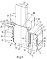
- Fig. 2
- in schematischer Darstellung eine perspektivische Darstellung auf das Ende eines Rotors in einem Elektromotor nach
Fig. 1 . - Der in
Fig. 1 in Teildarstellung gezeigte Elektromotor 1 besteht im Wesentlichen aus einem Stator 2 und einem Rotor 3, dessen Rotorwelle 4 in endseitigen Lagerschildern des Stators 2 drehbar gelagert ist. InFig. 1 ist ein Lagerschild 5 gezeigt, in dem ein Ende der Rotorwelle 4 in einem Lager 6 gehalten ist. Das Lager 6 ist ein Wälzlager in Form eines Kugellagers und weist einen Innenring 16 sowie einen Außenring 26 auf, zwischen denen Kugeln 7 als Wälzkörper gehalten sind. Die Rotorwelle 4 stützt sich mit einer Schulter 55 am Innenring 16 des Lagers 6 ab. - Der Lagerschild 5 ist mittels nicht näher dargestellten Befestigungen 8 stirnseitig am vorteilhaft zylindrischen Stator 2 festgelegt, insbesondere verschraubt.
- Zwischen dem Rotor 3 und dem Lagerschild 5 ist ein Bremselement 30 angeordnet, welches im gezeigten Ausführungsbeispiel als Bremstopf 31 mit einem Boden 32 und einer Umfangswand 33 ausgebildet ist. Der Bremstopf 31 weist ferner eine zentrale Nabe 35 auf, die auf der Rotorwelle 4 geführt ist. Die zentrale Nabe 35 bildet ein Gleitlager auf der Rotorwelle 4 und erstreckt sich über die gesamte Höhe H des Bremstopfes 31, so dass eine im Wesentlichen spielfreie, sichere axiale Führung des Bremstopfes 31 auf der Rotorwelle 4 gegeben ist.
- Wie die
Figuren 1 und2 zeigen, ist die axiale Länge L der Nabe 35 im gezeigten Ausführungsbeispiel länger als die Höhe H des Bremstopfes 31 ausgeführt, insbesondere länger als die Höhe H der Umfangswand 33 des Bremstopfes 31. Durch die große axiale Länge L ist eine gute Tragfähigkeit bei kleiner Flächenbelastung gewährleistet. Es kann zweckmäßig sein, wenn die Nabe 35 innerhalb des Bremstopfes 31 endet oder kürzer als die axiale Länge des Bremstopfes 31 ausgeführt ist. - An ihrem einen, dem Rotor 3 zugewandten Ende 34 steht die Nabe 35 aus dem Bremstopf 31 vor; an ihrem anderen Ende 36 ragt die Nabe 35 aus dem Boden 32 des Bremstopfes 31 heraus. Die Nabe 35 steht also an beiden axialen Enden 34 und 36 aus dem Bremstopf 31 heraus.
- In der Stirnseite 9 des Rotors 3 ist nahe der Rotorwelle 4 eine Ringausnehmung 10 ausgebildet, in der die Nabe 35 liegt. Im Boden 11 der Ringausnehmung 10 ist eine das Ende 34 der Nabe 35 aufnehmende Ringvertiefung 12 vorgesehen, die der Wandstärke der Nabe 35 angepasst gestaltet ist und deren Boden 14 einen Anschlag 15 für den Verschiebeweg v der Nabe 35 bildet. Es kann zweckmäßig sein, die Ringvertiefung 12 breiter als die Wandstärke der Nabe 35 auszuführen, vorteilhaft so groß wie die Ringausnehmung 10 selbst, wie in punktierter Linie in
Fig. 1 oben links dargestellt ist. - Das andere Ende 36 der Nabe ragt in einen Anschlagtopf 20, dessen Boden 21 von der Rotorwelle 4 durchragt ist und dessen Öffnung 22 dem Ende 36 der Nabe 35 zugewandt liegt. Der Anschlagtopf 20 stützt sich in der einen Axialrichtung am Lagerschild 5 ab, im gezeigten Ausführungsbeispiel stützt sich der Anschlagtopf 20 über das Lager 6 am Lagerschild 5 ab. Wie
Fig. 1 zeigt, liegt der Boden 21 des Anschlagtopfes 20 axial am Innenring 16 des Lagers 6 an, wodurch die Abstützung am Lagerschild 5 gewährleistet ist. In der anderen Axialrichtung liegt der Anschlagtopf 20 mit seinem Boden 21 an einer Ringschulter 60 der Rotorwelle 4 an, so dass der Anschlagtopf 20 zwischen dem Ringanschlag 60 und dem Innenring 16 des Lagers 6 sicher gehalten ist. - Der Bremstopf 31 übergreift die Stirnseite 9 des Rotors 3, wobei die Umfangswand 33 das Ende 13 des Rotors 3 überlappt. Die Überlappung u ist am größten, wenn der Bremstopf in seiner am Rotor 3 angezogenen Stellung gemäß
Fig. 1 liegt, in der das Ende 34 der Nabe 35 am Anschlag 15, d. h. am Boden 14 der Ringvertiefung 12 anliegt. In der anderen, nicht angezogenen Stellung kann sich der Bremstopf 31 bei zunehmendem Verschleiß der im Lagerschild 5 gehaltenen Bremskörper 51 so weit verlagern, bis das aus dem Boden 32 in Richtung auf das Lagerschild 5 vorstehende Ende 36 der Nabe 35 am Boden 21 des Anschlagtopfes 20 anstößt. Der Boden 21 des Anschlagtopfes 20 bildet einen weiteren Anschlag 25 für die Nabe 35 bzw. für den Bremstopf 31. Zwischen den Anschlägen 15 und 25 kann sich der Bremstopf 31 maximal bewegen; dieser maximale Verschiebeweg ist mit v bezeichnet. - Die Überlappung u ist derart bemessen, dass bei einer Lage des Bremstopfes 31 sowohl am ersten Anschlag 15 als auch am zweiten Anschlag 25 eine Überdeckung zwischen dem Ende 13 des Rotors 3 und der Umfangswand 33 des Bremstopfes 31 gegeben ist. Entsprechend ist die Tiefe T des Anschlagtopfes 20 derart bemessen, dass das freie Ende 36 der Nabe 35 mit der Umfangswand 23 des Anschlagtopfes 20 eine Überdeckung b aufweist, die auch dann noch besteht, wenn die Nabe 35 am ersten Anschlag 15 anliegt.
- Zwischen dem Boden 11 der Ringausnehmung 10 und dem Boden 32 des Bremstopfes 31 ist eine Feder 18 angeordnet, die im Ausführungsbeispiel als Schraubenfeder gestaltet ist. Die Feder 18 liegt mit dem einen Ende auf dem Boden 11 in der Ringausnehmung 10 auf und mit dem anderen Ende am Boden 32 des Bremstopfes 31 an. Wird die Ringvertiefung 12 breiter ausgeführt, z. B. bis zur Mantelfläche der Ringausnehmung 10, kann sich die Feder 18 auch auf dem Boden 14 der Ringvertiefung 12 anstelle des Bodens 11 abstützen.
- Wie in
Fig. 1 gezeigt, liegt die Feder 18 somit innerhalb des Bremstopfes 31, also im Innenraum des Bremstopfes 31. Vorteilhaft ist die Feder 18 zwischen der Nabe 35 und der Umfangswand 33 angeordnet, insbesondere im Raumbereich der Ringausnehmung 10. Zweckmäßig liegt die als Schraubenfeder ausgebildete Feder 18 koaxial zur Nabe 35. - In einer alternativen Ausführungsform kann die Feder 18' auch in einem Ringraum 10' zwischen einer Teillänge der Nabe 35 und dem Rotor 3 bzw. der Rotorwelle 4 angeordnet werden, wie in
Fig. 1 oben links strichliert dargestellt ist. - Ist der Elektromotor 1 eingeschaltet und dreht die Rotorwelle 4 um die Drehachse 40 z. B. in Pfeilrichtung 41, wird aufgrund des elektromagnetischen Flusses des Elektromotors 1, der auch den aus magnetisierbarem Material bestehenden Bremstopf 31 durchsetzt, in Pfeilrichtung 44 gegen die Stirnseite 9 des Rotors 3 angezogen, bis das Ende 34 der Nabe 35 am Anschlag 15 anliegt. Die Verschiebung des Bremstopfes 31 auf der Rotorwelle 4 in Pfeilrichtung 44 erfolgt gegen die Kraft der Feder 18. In der in
Fig. 1 dargestellten Betriebsstellung rotiert der Bremstopf 31 zusammen mit dem Rotor 3 um die Drehachse 40. - Dem Boden 32 des Bremstopfes 31 liegt am Lagerschild 5 eine Bremsfläche 50 gegenüber, die im gezeigten Ausführungsbeispiel durch die Bremskörper 51 ausgebildet ist, die im Lagerschild 5 fixiert sind. Der Bremskörper 51 kann als Bremsring gestaltet sein oder aus einzelnen Teilringsegmenten, die in Drehrichtung des Bremstopfes 31 mit Abstand zueinander liegen.
- Auf der Stirnseite 9 des Rotors 3 sind Keilelemente 47 vorgesehen, wobei in Umfangsrichtung des Rotors mehrere mit Abstand zueinander liegende Keilelemente 47 vorgesehen sind. Vorteilhaft sind die Keilelemente 47 symmetrisch ausgebildet, d. h., in beiden Drehrichtungen des Rotors ist eine Keilfläche 48 ausgebildet. Jedem Keilelement 47 des Rotors 3 ist ein inneres Keilelement 37 am Boden 32 des Bremstopfes 31 zugeordnet. Die Keilelemente 37 und 47 haben in Umfangsrichtung des Rotors 3 ansteigende, bzw. abfallende Keilflächen, wobei die im Ausführungsbeispiel gezeigten Keilflächen 48 in der einen Drehrichtung 41 abfallen, während die Keilflächen 38 der Keilelemente 37 des Bremstopfes 31 in der Drehrichtung 41 ansteigen. Die Keilflächen 38, 48 der Keilelemente 37, 47 sind einander komplementär ausgebildet und überlappen einander axial. Entsprechend sind an den Keilelementen 37, 47 nicht näher dargestellte Keilflächen ausgebildet, die bei Abbremsen eines entgegen der Drehrichtung 41 rotierenden Rotors 4 miteinander in Eingriff treten.
- Wird der Elektromotor 1 ausgeschaltet, verschiebt sich der Bremstopf 31 unter der Kraft der Feder 18 entgegen Pfeilrichtung 44 über einen Verschiebeweg v, bis der Boden 32 des Bremstopfes 31 an der Bremsfläche 50 des Lagerschildes 5 zu Anlage kommt; der Bremstopf 31 wird abgebremst. Da der Bremstopf 31 auf der Rotorwelle 4 mit der Nabe 35 als Gleitlager gelagert ist, dreht sich bei langsamer werdendem Bremstopf 31 die Rotorwelle 4 bzw. der Rotor 3 relativ zum Bremstopf 31 so weit, bis die komplementären Keilflächen 38 und 48 der Keilelemente 37 und 47 aufeinander gleiten und durch den Eingriff eine axiale Keilkraft entgegen Pfeilrichtung 44 aufbauen, durch die der Bremstopf 31 noch stärker an die Bremsflächen 50 angedrückt wird und somit noch stärker verzögert. Da der Rotor 3 über die Keilelemente 37, 47 in Drehrichtung 41 in drehfestem Eingriff mit dem Bremstopf 31 steht, erfolgt eine Abbremsung des Rotors 3 selbst bis zum Stillstand. Eine in Drehrichtung 41 rotierende Rotorwelle 4 wird somit bei Abschalten des Erregerstroms des Elektromotors 1 durch den Bremstopf 31 über die Bremsflächen 50 am Lagerschild 5 bis zum Stillstand rasch abgebremst. Bei einer Rotation des Rotor 3 entgegen der Drehrichtung 41 erfolgt eine entsprechende Bremsung durch andere Keilflächen.
- Der Bremstopf 31 hat geschlossene Wandungen, d. h. die Umfangswand 33 wie der Boden 32 bilden geschlossene Flächen, so dass kein Schmutz, Bremsabrieb oder dgl. in das Innere des Bremstopfes 31 gelangen kann. Da die Umfangswand 33 in allen Stellungen des Bremstopfes 31 das Ende 13 des Rotors 3 überlappt, ist ein im Wesentlichen geschlossener Bremstopf 31 erzielt, dessen Innenraum 39 gegenüber der Umgebung weitgehend abgedichtet ist. Dabei erfolgt die Abdichtung im Bereich der Überlappung u durch eine Spaltdichtung; entsprechend ist durch die Überlappung b des Anschlagtopfes 20 mit dem Ende 36 der Nabe 35 eine Labyrinthdichtung ausgebildet, so dass ein Eintreten von Schmutz, Abrieb und dgl. im Bereich der Nabe 35 ebenfalls weitgehend vermieden ist.
- Alle wesentlichen Funktionselemente des Bremssystems liegen im geschützten Innenraum 39 des Bremstopfes 31.
- Der Bremstopf 31 kann aus einzelnen Elementen zusammengefügt, also gebaut werden, oder - wie im Ausführungsbeispiel gezeigt - als einteiliges Bauteil gefertigt sein, z. B. als Gussteil hergestellt sein oder als Tiefziehteil gefertigt sein.
Claims (13)
- Elektromotor mit einem zwischen dem Rotor (3) und einem Lagerschild (5) des Elektromotors (1) angeordneten Bremselement (30), welches im Betrieb des Elektromotors (1) vom elektromagnetischen Fluss des Elektromotors (1) durchflossen und axial gegen die Kraft einer Feder (18) an die Stirnseite (9) des Rotors (3) magnetisch angezogen wird und mit dem Rotor (3) rotiert, wobei das Bremselement (30) auf der Rotorwelle (4) geführt und relativ zur Rotorwelle (4) um einen Drehwinkel drehbar ist, und mit einer am Lagerschild (5) ausgebildeten Bremsfläche (50) ausgestattet ist, an die beim Ausschalten des Elektromotors (1) das Bremselement (30) unter der Wirkung der Feder (18) axial angedrückt wird, sowie mit zwischen dem Bremselement (30) und dem Rotor (3) angeordneten Keilelementen (37, 47) ausgestattet ist, die bei Drehung des Rotors (3) relativ zum Bremselement (30) aufeinander aufgleiten und eine axiale Keilkraft erzeugen, die die Anlagekraft des Bremselementes (30) auf der Bremsfläche (50) erhöht, wobei das Bremselement (30) ein mit geschlossenen Wandungen ausgeführter Bremstopf (31) ist, und die Keilelemente (37, 47) innerhalb des geschlossenen Bremstopfes (31) liegen,
dadurch gekennzeichnet, dass der Bremstopf (31) das Ende (13) des Rotors (3) übergreift, dass der Bremstopf (31) eine zentrale Nabe (35) aufweist, die auf der Rotorwelle (4) geführt ist, und dass die Feder (18) zwischen der Nabe (35) und der Umfangswand (33) des Bremstopfes (31) liegt. - Elektromotor nach Anspruch 1,
dadurch gekennzeichnet, dass eine Umfangswand (33) des Bremstopfes (31) und das Ende (13) des Rotors (3) in allen Stellungen des Bremstopfes (31) einander überlappen. - Elektromotor nach Anspruch 1,
dadurch gekennzeichnet, dass die Nabe (35) ein Gleitlager bildet. - Elektromotor nach einem der Ansprüche 1 bis 3,
dadurch gekennzeichnet, dass sich die Nabe (35) über die gesamte Höhe (H) des Bremstopfes (31) erstreckt. - Elektromotor nach einem der Ansprüche 1 bis 4,
dadurch gekennzeichnet, dass die Nabe (35) aus dem Boden (32) des Bremstopfes (31) in Richtung auf das Lagerschild (5) vorsteht. - Elektromotor nach einem der Ansprüche 1 bis 5,
dadurch gekennzeichnet, dass die Nabe (35) länger als die Höhe (H) der Umfangswand (33) des Bremstopfes (31) ist. - Elektromotor nach einem der Ansprüche 1 bis 6,
dadurch gekennzeichnet, dass der axiale Verschiebeweg (v) der Nabe (35) durch Anschläge (15, 25) begrenzt ist. - Elektromotor nach Anspruch 7,
dadurch gekennzeichnet, dass ein erster Anschlag (15) durch den Rotor (3) und ein zweiter Anschlag (25) durch das Lagerschild (5) gebildet ist. - Elektromotor nach Anspruch 8,
dadurch gekennzeichnet, dass der zweite Anschlag (25) durch ein im Lagerschild (5) gehaltenes Lager (6) der Rotorwelle (4) gebildet ist. - Elektromotor nach Anspruch 9,
dadurch gekennzeichnet, dass zwischen dem Lager (6) und dem Bremstopf (31) ein Anschlagtopf (20) vorgesehen ist, in den ein Ende der Nabe (35) einragt. - Elektromotor nach Anspruch 10,
dadurch gekennzeichnet, dass die Umfangswand (23) des Anschlagtopfes (20) in allen Stellungen des Bremstopfes (31) das einragende Ende (36) der Nabe (35) überlappt. - Elektromotor nach einem der Ansprüche 1 bis 11,
dadurch gekennzeichnet, dass die Feder (18) innerhalb der geschlossenen Wandungen des Bremstopfes (31) liegt - Elektromotor nach einem der Ansprüche 1 bis 12,
dadurch gekennzeichnet, dass die Feder (18) zwischen der Nabe (35) und dem Rotor (3) angeordnet ist.
Priority Applications (1)
| Application Number | Priority Date | Filing Date | Title |
|---|---|---|---|
| EP12005713.8A EP2696483B1 (de) | 2012-08-07 | 2012-08-07 | Elektromotor mit Abschaltbremse |
Applications Claiming Priority (1)
| Application Number | Priority Date | Filing Date | Title |
|---|---|---|---|
| EP12005713.8A EP2696483B1 (de) | 2012-08-07 | 2012-08-07 | Elektromotor mit Abschaltbremse |
Publications (2)
| Publication Number | Publication Date |
|---|---|
| EP2696483A1 EP2696483A1 (de) | 2014-02-12 |
| EP2696483B1 true EP2696483B1 (de) | 2017-11-15 |
Family
ID=46690361
Family Applications (1)
| Application Number | Title | Priority Date | Filing Date |
|---|---|---|---|
| EP12005713.8A Active EP2696483B1 (de) | 2012-08-07 | 2012-08-07 | Elektromotor mit Abschaltbremse |
Country Status (1)
| Country | Link |
|---|---|
| EP (1) | EP2696483B1 (de) |
Families Citing this family (1)
| Publication number | Priority date | Publication date | Assignee | Title |
|---|---|---|---|---|
| CN109278067A (zh) * | 2018-11-30 | 2019-01-29 | 上海宇塚电子科技有限公司 | 机器人关节模组中盘式制动装置结构 |
Family Cites Families (4)
| Publication number | Priority date | Publication date | Assignee | Title |
|---|---|---|---|---|
| DE3407731A1 (de) | 1984-03-02 | 1985-09-05 | Licentia Patent-Verwaltungs-Gmbh, 6000 Frankfurt | Elektromotor mit automatisch wirkender bremse |
| DE4033213C2 (de) * | 1990-10-19 | 1996-05-23 | Elektromotorenwerk Gruenhain G | Bremsanordnung für Elektromotoren |
| HU223767B1 (hu) * | 1999-12-09 | 2005-01-28 | Pál Kiss | Belső fékes elrendezés kis teljesítményű aszinkron motorokhoz |
| CN1510817A (zh) * | 2002-12-24 | 2004-07-07 | 苏州宝时得电动工具有限公司 | 带制动装置的电动机 |
-
2012
- 2012-08-07 EP EP12005713.8A patent/EP2696483B1/de active Active
Non-Patent Citations (1)
| Title |
|---|
| None * |
Also Published As
| Publication number | Publication date |
|---|---|
| EP2696483A1 (de) | 2014-02-12 |
Similar Documents
| Publication | Publication Date | Title |
|---|---|---|
| EP0175996B1 (de) | Antriebseinheit, insbesondere zum Verstellen von Fensterscheiben, Schiebedächern, Sitzen und ähnlichen Kraftfahrzeugteilen | |
| DE102011050814B3 (de) | Welle mit einem Lager | |
| EP0392146B1 (de) | Wälzlagerkäfig | |
| EP2354577B1 (de) | Lagerung | |
| DE1043742B (de) | Leitspindeltrieb | |
| EP4455505A2 (de) | Scheibenbremse für ein nutzfahrzeug und bremsbelagsatz | |
| DE2913885A1 (de) | Lamellenjalousie mit senkrecht angeordneten lamellen | |
| DE102010063181A1 (de) | Nabe für eine Windturbine | |
| EP0151427B1 (de) | Federüberwachungsgerät | |
| DE102007023712B4 (de) | Antrieb mit einem Elektromotor, einem Gehäuse und einer richtungsabhängigen Bremse | |
| DE69904110T2 (de) | Elektromagnetische Betätigungseinrichtung mit Gewindespindelantrieb | |
| EP3245127B1 (de) | Brems-rasteinheit für kommandogeber | |
| DE69419144T2 (de) | Sicherheitsvorrichtung gegen störung für flugregelsystem | |
| EP3655256B1 (de) | Radnabe und ein system aus radnabe und bremselement | |
| EP2696483B1 (de) | Elektromotor mit Abschaltbremse | |
| DE19751029B4 (de) | Zweimassen-Dämpfungsschwungrad für Kraftfahrzeuge | |
| DE102007052280B4 (de) | Richtungsunabhängig ansprechender Geschwindigkeitsbegrenzer | |
| DE102015001442B4 (de) | Bremsanordnung mit einem Bremsbelagträger und einem Mitnehmer | |
| EP3106698A1 (de) | Mechanisches getriebe mit integrierter lastmomentsperre | |
| DE10234371B4 (de) | Blockierbare Feststellvorrichtung | |
| EP1643150A1 (de) | Haltevorrichtung | |
| DE2134506B2 (de) | Kupplung mit drehmomentabhängiger Stillsetzung | |
| DE102007035450A1 (de) | Wellenschalter | |
| DE3802017C2 (de) | Automatische Nachstellvorrichtung für eine Scheibenbremse | |
| DE10330307A1 (de) | Bremseinheit für Zahnstangenantrieb |
Legal Events
| Date | Code | Title | Description |
|---|---|---|---|
| AK | Designated contracting states |
Kind code of ref document: A1 Designated state(s): AL AT BE BG CH CY CZ DE DK EE ES FI FR GB GR HR HU IE IS IT LI LT LU LV MC MK MT NL NO PL PT RO RS SE SI SK SM TR |
|
| AX | Request for extension of the european patent |
Extension state: BA ME |
|
| PUAI | Public reference made under article 153(3) epc to a published international application that has entered the european phase |
Free format text: ORIGINAL CODE: 0009012 |
|
| 17P | Request for examination filed |
Effective date: 20140604 |
|
| RBV | Designated contracting states (corrected) |
Designated state(s): AL AT BE BG CH CY CZ DE DK EE ES FI FR GB GR HR HU IE IS IT LI LT LU LV MC MK MT NL NO PL PT RO RS SE SI SK SM TR |
|
| GRAP | Despatch of communication of intention to grant a patent |
Free format text: ORIGINAL CODE: EPIDOSNIGR1 |
|
| INTG | Intention to grant announced |
Effective date: 20170606 |
|
| GRAS | Grant fee paid |
Free format text: ORIGINAL CODE: EPIDOSNIGR3 |
|
| GRAA | (expected) grant |
Free format text: ORIGINAL CODE: 0009210 |
|
| AK | Designated contracting states |
Kind code of ref document: B1 Designated state(s): AL AT BE BG CH CY CZ DE DK EE ES FI FR GB GR HR HU IE IS IT LI LT LU LV MC MK MT NL NO PL PT RO RS SE SI SK SM TR |
|
| REG | Reference to a national code |
Ref country code: CH Ref legal event code: EP Ref country code: GB Ref legal event code: FG4D Free format text: NOT ENGLISH Ref country code: AT Ref legal event code: REF Ref document number: 947179 Country of ref document: AT Kind code of ref document: T Effective date: 20171115 |
|
| REG | Reference to a national code |
Ref country code: IE Ref legal event code: FG4D Free format text: LANGUAGE OF EP DOCUMENT: GERMAN |
|
| REG | Reference to a national code |
Ref country code: DE Ref legal event code: R096 Ref document number: 502012011636 Country of ref document: DE |
|
| REG | Reference to a national code |
Ref country code: NL Ref legal event code: MP Effective date: 20171115 |
|
| REG | Reference to a national code |
Ref country code: LT Ref legal event code: MG4D |
|
| PG25 | Lapsed in a contracting state [announced via postgrant information from national office to epo] |
Ref country code: NL Free format text: LAPSE BECAUSE OF FAILURE TO SUBMIT A TRANSLATION OF THE DESCRIPTION OR TO PAY THE FEE WITHIN THE PRESCRIBED TIME-LIMIT Effective date: 20171115 Ref country code: ES Free format text: LAPSE BECAUSE OF FAILURE TO SUBMIT A TRANSLATION OF THE DESCRIPTION OR TO PAY THE FEE WITHIN THE PRESCRIBED TIME-LIMIT Effective date: 20171115 Ref country code: SE Free format text: LAPSE BECAUSE OF FAILURE TO SUBMIT A TRANSLATION OF THE DESCRIPTION OR TO PAY THE FEE WITHIN THE PRESCRIBED TIME-LIMIT Effective date: 20171115 Ref country code: FI Free format text: LAPSE BECAUSE OF FAILURE TO SUBMIT A TRANSLATION OF THE DESCRIPTION OR TO PAY THE FEE WITHIN THE PRESCRIBED TIME-LIMIT Effective date: 20171115 Ref country code: NO Free format text: LAPSE BECAUSE OF FAILURE TO SUBMIT A TRANSLATION OF THE DESCRIPTION OR TO PAY THE FEE WITHIN THE PRESCRIBED TIME-LIMIT Effective date: 20180215 Ref country code: LT Free format text: LAPSE BECAUSE OF FAILURE TO SUBMIT A TRANSLATION OF THE DESCRIPTION OR TO PAY THE FEE WITHIN THE PRESCRIBED TIME-LIMIT Effective date: 20171115 |
|
| PG25 | Lapsed in a contracting state [announced via postgrant information from national office to epo] |
Ref country code: RS Free format text: LAPSE BECAUSE OF FAILURE TO SUBMIT A TRANSLATION OF THE DESCRIPTION OR TO PAY THE FEE WITHIN THE PRESCRIBED TIME-LIMIT Effective date: 20171115 Ref country code: HR Free format text: LAPSE BECAUSE OF FAILURE TO SUBMIT A TRANSLATION OF THE DESCRIPTION OR TO PAY THE FEE WITHIN THE PRESCRIBED TIME-LIMIT Effective date: 20171115 Ref country code: BG Free format text: LAPSE BECAUSE OF FAILURE TO SUBMIT A TRANSLATION OF THE DESCRIPTION OR TO PAY THE FEE WITHIN THE PRESCRIBED TIME-LIMIT Effective date: 20180215 Ref country code: LV Free format text: LAPSE BECAUSE OF FAILURE TO SUBMIT A TRANSLATION OF THE DESCRIPTION OR TO PAY THE FEE WITHIN THE PRESCRIBED TIME-LIMIT Effective date: 20171115 Ref country code: GR Free format text: LAPSE BECAUSE OF FAILURE TO SUBMIT A TRANSLATION OF THE DESCRIPTION OR TO PAY THE FEE WITHIN THE PRESCRIBED TIME-LIMIT Effective date: 20180216 |
|
| PG25 | Lapsed in a contracting state [announced via postgrant information from national office to epo] |
Ref country code: DK Free format text: LAPSE BECAUSE OF FAILURE TO SUBMIT A TRANSLATION OF THE DESCRIPTION OR TO PAY THE FEE WITHIN THE PRESCRIBED TIME-LIMIT Effective date: 20171115 Ref country code: CY Free format text: LAPSE BECAUSE OF FAILURE TO SUBMIT A TRANSLATION OF THE DESCRIPTION OR TO PAY THE FEE WITHIN THE PRESCRIBED TIME-LIMIT Effective date: 20171115 Ref country code: EE Free format text: LAPSE BECAUSE OF FAILURE TO SUBMIT A TRANSLATION OF THE DESCRIPTION OR TO PAY THE FEE WITHIN THE PRESCRIBED TIME-LIMIT Effective date: 20171115 Ref country code: CZ Free format text: LAPSE BECAUSE OF FAILURE TO SUBMIT A TRANSLATION OF THE DESCRIPTION OR TO PAY THE FEE WITHIN THE PRESCRIBED TIME-LIMIT Effective date: 20171115 Ref country code: SK Free format text: LAPSE BECAUSE OF FAILURE TO SUBMIT A TRANSLATION OF THE DESCRIPTION OR TO PAY THE FEE WITHIN THE PRESCRIBED TIME-LIMIT Effective date: 20171115 |
|
| REG | Reference to a national code |
Ref country code: DE Ref legal event code: R097 Ref document number: 502012011636 Country of ref document: DE |
|
| REG | Reference to a national code |
Ref country code: FR Ref legal event code: PLFP Year of fee payment: 7 |
|
| PG25 | Lapsed in a contracting state [announced via postgrant information from national office to epo] |
Ref country code: SM Free format text: LAPSE BECAUSE OF FAILURE TO SUBMIT A TRANSLATION OF THE DESCRIPTION OR TO PAY THE FEE WITHIN THE PRESCRIBED TIME-LIMIT Effective date: 20171115 Ref country code: RO Free format text: LAPSE BECAUSE OF FAILURE TO SUBMIT A TRANSLATION OF THE DESCRIPTION OR TO PAY THE FEE WITHIN THE PRESCRIBED TIME-LIMIT Effective date: 20171115 Ref country code: IT Free format text: LAPSE BECAUSE OF FAILURE TO SUBMIT A TRANSLATION OF THE DESCRIPTION OR TO PAY THE FEE WITHIN THE PRESCRIBED TIME-LIMIT Effective date: 20171115 Ref country code: PL Free format text: LAPSE BECAUSE OF FAILURE TO SUBMIT A TRANSLATION OF THE DESCRIPTION OR TO PAY THE FEE WITHIN THE PRESCRIBED TIME-LIMIT Effective date: 20171115 |
|
| PLBE | No opposition filed within time limit |
Free format text: ORIGINAL CODE: 0009261 |
|
| STAA | Information on the status of an ep patent application or granted ep patent |
Free format text: STATUS: NO OPPOSITION FILED WITHIN TIME LIMIT |
|
| PG25 | Lapsed in a contracting state [announced via postgrant information from national office to epo] |
Ref country code: MT Free format text: LAPSE BECAUSE OF FAILURE TO SUBMIT A TRANSLATION OF THE DESCRIPTION OR TO PAY THE FEE WITHIN THE PRESCRIBED TIME-LIMIT Effective date: 20171115 |
|
| REG | Reference to a national code |
Ref country code: DE Ref legal event code: R082 Ref document number: 502012011636 Country of ref document: DE Representative=s name: PATENTANWAELTE DIPL.-ING. W. JACKISCH & PARTNE, DE Ref country code: DE Ref legal event code: R082 Ref document number: 502012011636 Country of ref document: DE Representative=s name: PATENTANWAELTE DIPL.-ING. WALTER JACKISCH & PA, DE Ref country code: DE Ref legal event code: R081 Ref document number: 502012011636 Country of ref document: DE Owner name: ANDREAS STIHL AG & CO. KG, DE Free format text: FORMER OWNER: VIKING GMBH, LANGKAMPFEN, AT |
|
| 26N | No opposition filed |
Effective date: 20180817 |
|
| REG | Reference to a national code |
Ref country code: GB Ref legal event code: 732E Free format text: REGISTERED BETWEEN 20180927 AND 20181005 |
|
| PG25 | Lapsed in a contracting state [announced via postgrant information from national office to epo] |
Ref country code: SI Free format text: LAPSE BECAUSE OF FAILURE TO SUBMIT A TRANSLATION OF THE DESCRIPTION OR TO PAY THE FEE WITHIN THE PRESCRIBED TIME-LIMIT Effective date: 20171115 |
|
| REG | Reference to a national code |
Ref country code: BE Ref legal event code: PD Owner name: ANDREAS STIHL AG & CO. KG; DE Free format text: DETAILS ASSIGNMENT: CHANGE OF OWNER(S), CESSION; FORMER OWNER NAME: VIKING GMBH Effective date: 20181009 |
|
| REG | Reference to a national code |
Ref country code: AT Ref legal event code: PC Ref document number: 947179 Country of ref document: AT Kind code of ref document: T Owner name: ANDREAS STIHL AG & CO. KG, DE Effective date: 20181203 |
|
| PG25 | Lapsed in a contracting state [announced via postgrant information from national office to epo] |
Ref country code: MC Free format text: LAPSE BECAUSE OF FAILURE TO SUBMIT A TRANSLATION OF THE DESCRIPTION OR TO PAY THE FEE WITHIN THE PRESCRIBED TIME-LIMIT Effective date: 20171115 |
|
| REG | Reference to a national code |
Ref country code: CH Ref legal event code: PL |
|
| PG25 | Lapsed in a contracting state [announced via postgrant information from national office to epo] |
Ref country code: LI Free format text: LAPSE BECAUSE OF NON-PAYMENT OF DUE FEES Effective date: 20180831 Ref country code: CH Free format text: LAPSE BECAUSE OF NON-PAYMENT OF DUE FEES Effective date: 20180831 Ref country code: LU Free format text: LAPSE BECAUSE OF NON-PAYMENT OF DUE FEES Effective date: 20180807 |
|
| REG | Reference to a national code |
Ref country code: IE Ref legal event code: MM4A |
|
| PG25 | Lapsed in a contracting state [announced via postgrant information from national office to epo] |
Ref country code: IE Free format text: LAPSE BECAUSE OF NON-PAYMENT OF DUE FEES Effective date: 20180807 |
|
| PG25 | Lapsed in a contracting state [announced via postgrant information from national office to epo] |
Ref country code: TR Free format text: LAPSE BECAUSE OF FAILURE TO SUBMIT A TRANSLATION OF THE DESCRIPTION OR TO PAY THE FEE WITHIN THE PRESCRIBED TIME-LIMIT Effective date: 20171115 |
|
| PG25 | Lapsed in a contracting state [announced via postgrant information from national office to epo] |
Ref country code: HU Free format text: LAPSE BECAUSE OF FAILURE TO SUBMIT A TRANSLATION OF THE DESCRIPTION OR TO PAY THE FEE WITHIN THE PRESCRIBED TIME-LIMIT; INVALID AB INITIO Effective date: 20120807 Ref country code: PT Free format text: LAPSE BECAUSE OF FAILURE TO SUBMIT A TRANSLATION OF THE DESCRIPTION OR TO PAY THE FEE WITHIN THE PRESCRIBED TIME-LIMIT Effective date: 20171115 |
|
| PG25 | Lapsed in a contracting state [announced via postgrant information from national office to epo] |
Ref country code: MK Free format text: LAPSE BECAUSE OF NON-PAYMENT OF DUE FEES Effective date: 20171115 |
|
| PG25 | Lapsed in a contracting state [announced via postgrant information from national office to epo] |
Ref country code: AL Free format text: LAPSE BECAUSE OF FAILURE TO SUBMIT A TRANSLATION OF THE DESCRIPTION OR TO PAY THE FEE WITHIN THE PRESCRIBED TIME-LIMIT Effective date: 20171115 Ref country code: IS Free format text: LAPSE BECAUSE OF FAILURE TO SUBMIT A TRANSLATION OF THE DESCRIPTION OR TO PAY THE FEE WITHIN THE PRESCRIBED TIME-LIMIT Effective date: 20180315 |
|
| PGFP | Annual fee paid to national office [announced via postgrant information from national office to epo] |
Ref country code: GB Payment date: 20220823 Year of fee payment: 11 Ref country code: AT Payment date: 20220818 Year of fee payment: 11 |
|
| PGFP | Annual fee paid to national office [announced via postgrant information from national office to epo] |
Ref country code: FR Payment date: 20220824 Year of fee payment: 11 Ref country code: BE Payment date: 20220825 Year of fee payment: 11 |
|
| REG | Reference to a national code |
Ref country code: AT Ref legal event code: MM01 Ref document number: 947179 Country of ref document: AT Kind code of ref document: T Effective date: 20230807 |
|
| PG25 | Lapsed in a contracting state [announced via postgrant information from national office to epo] |
Ref country code: AT Free format text: LAPSE BECAUSE OF NON-PAYMENT OF DUE FEES Effective date: 20230807 |
|
| GBPC | Gb: european patent ceased through non-payment of renewal fee |
Effective date: 20230807 |
|
| PG25 | Lapsed in a contracting state [announced via postgrant information from national office to epo] |
Ref country code: AT Free format text: LAPSE BECAUSE OF NON-PAYMENT OF DUE FEES Effective date: 20230807 |
|
| REG | Reference to a national code |
Ref country code: BE Ref legal event code: MM Effective date: 20230831 |
|
| PG25 | Lapsed in a contracting state [announced via postgrant information from national office to epo] |
Ref country code: GB Free format text: LAPSE BECAUSE OF NON-PAYMENT OF DUE FEES Effective date: 20230807 |
|
| PG25 | Lapsed in a contracting state [announced via postgrant information from national office to epo] |
Ref country code: GB Free format text: LAPSE BECAUSE OF NON-PAYMENT OF DUE FEES Effective date: 20230807 Ref country code: FR Free format text: LAPSE BECAUSE OF NON-PAYMENT OF DUE FEES Effective date: 20230831 |
|
| PG25 | Lapsed in a contracting state [announced via postgrant information from national office to epo] |
Ref country code: BE Free format text: LAPSE BECAUSE OF NON-PAYMENT OF DUE FEES Effective date: 20230831 |
|
| PGFP | Annual fee paid to national office [announced via postgrant information from national office to epo] |
Ref country code: DE Payment date: 20250827 Year of fee payment: 14 |