EP2697106B1 - Procédé permettant de faire fonctionner un système de freinage - Google Patents
Procédé permettant de faire fonctionner un système de freinage Download PDFInfo
- Publication number
- EP2697106B1 EP2697106B1 EP12715043.1A EP12715043A EP2697106B1 EP 2697106 B1 EP2697106 B1 EP 2697106B1 EP 12715043 A EP12715043 A EP 12715043A EP 2697106 B1 EP2697106 B1 EP 2697106B1
- Authority
- EP
- European Patent Office
- Prior art keywords
- pressure
- brake
- negative
- sensor
- motor
- Prior art date
- Legal status (The legal status is an assumption and is not a legal conclusion. Google has not performed a legal analysis and makes no representation as to the accuracy of the status listed.)
- Active
Links
Images
Classifications
-
- B—PERFORMING OPERATIONS; TRANSPORTING
- B60—VEHICLES IN GENERAL
- B60T—VEHICLE BRAKE CONTROL SYSTEMS OR PARTS THEREOF; BRAKE CONTROL SYSTEMS OR PARTS THEREOF, IN GENERAL; ARRANGEMENT OF BRAKING ELEMENTS ON VEHICLES IN GENERAL; PORTABLE DEVICES FOR PREVENTING UNWANTED MOVEMENT OF VEHICLES; VEHICLE MODIFICATIONS TO FACILITATE COOLING OF BRAKES
- B60T13/00—Transmitting braking action from initiating means to ultimate brake actuator with power assistance or drive; Brake systems incorporating such transmitting means, e.g. air-pressure brake systems
- B60T13/10—Transmitting braking action from initiating means to ultimate brake actuator with power assistance or drive; Brake systems incorporating such transmitting means, e.g. air-pressure brake systems with fluid assistance, drive, or release
- B60T13/58—Combined or convertible systems
- B60T13/585—Combined or convertible systems comprising friction brakes and retarders
- B60T13/586—Combined or convertible systems comprising friction brakes and retarders the retarders being of the electric type
-
- B—PERFORMING OPERATIONS; TRANSPORTING
- B60—VEHICLES IN GENERAL
- B60T—VEHICLE BRAKE CONTROL SYSTEMS OR PARTS THEREOF; BRAKE CONTROL SYSTEMS OR PARTS THEREOF, IN GENERAL; ARRANGEMENT OF BRAKING ELEMENTS ON VEHICLES IN GENERAL; PORTABLE DEVICES FOR PREVENTING UNWANTED MOVEMENT OF VEHICLES; VEHICLE MODIFICATIONS TO FACILITATE COOLING OF BRAKES
- B60T13/00—Transmitting braking action from initiating means to ultimate brake actuator with power assistance or drive; Brake systems incorporating such transmitting means, e.g. air-pressure brake systems
- B60T13/10—Transmitting braking action from initiating means to ultimate brake actuator with power assistance or drive; Brake systems incorporating such transmitting means, e.g. air-pressure brake systems with fluid assistance, drive, or release
- B60T13/24—Transmitting braking action from initiating means to ultimate brake actuator with power assistance or drive; Brake systems incorporating such transmitting means, e.g. air-pressure brake systems with fluid assistance, drive, or release the fluid being gaseous
- B60T13/46—Vacuum systems
- B60T13/52—Vacuum systems indirect, i.e. vacuum booster units
-
- B—PERFORMING OPERATIONS; TRANSPORTING
- B60—VEHICLES IN GENERAL
- B60T—VEHICLE BRAKE CONTROL SYSTEMS OR PARTS THEREOF; BRAKE CONTROL SYSTEMS OR PARTS THEREOF, IN GENERAL; ARRANGEMENT OF BRAKING ELEMENTS ON VEHICLES IN GENERAL; PORTABLE DEVICES FOR PREVENTING UNWANTED MOVEMENT OF VEHICLES; VEHICLE MODIFICATIONS TO FACILITATE COOLING OF BRAKES
- B60T8/00—Arrangements for adjusting wheel-braking force to meet varying vehicular or ground-surface conditions, e.g. limiting or varying distribution of braking force
- B60T8/32—Arrangements for adjusting wheel-braking force to meet varying vehicular or ground-surface conditions, e.g. limiting or varying distribution of braking force responsive to a speed condition, e.g. acceleration or deceleration
- B60T8/34—Arrangements for adjusting wheel-braking force to meet varying vehicular or ground-surface conditions, e.g. limiting or varying distribution of braking force responsive to a speed condition, e.g. acceleration or deceleration having a fluid pressure regulator responsive to a speed condition
- B60T8/42—Arrangements for adjusting wheel-braking force to meet varying vehicular or ground-surface conditions, e.g. limiting or varying distribution of braking force responsive to a speed condition, e.g. acceleration or deceleration having a fluid pressure regulator responsive to a speed condition having expanding chambers for controlling pressure, i.e. closed systems
- B60T8/4275—Pump-back systems
-
- B—PERFORMING OPERATIONS; TRANSPORTING
- B60—VEHICLES IN GENERAL
- B60T—VEHICLE BRAKE CONTROL SYSTEMS OR PARTS THEREOF; BRAKE CONTROL SYSTEMS OR PARTS THEREOF, IN GENERAL; ARRANGEMENT OF BRAKING ELEMENTS ON VEHICLES IN GENERAL; PORTABLE DEVICES FOR PREVENTING UNWANTED MOVEMENT OF VEHICLES; VEHICLE MODIFICATIONS TO FACILITATE COOLING OF BRAKES
- B60T13/00—Transmitting braking action from initiating means to ultimate brake actuator with power assistance or drive; Brake systems incorporating such transmitting means, e.g. air-pressure brake systems
- B60T13/10—Transmitting braking action from initiating means to ultimate brake actuator with power assistance or drive; Brake systems incorporating such transmitting means, e.g. air-pressure brake systems with fluid assistance, drive, or release
- B60T13/12—Transmitting braking action from initiating means to ultimate brake actuator with power assistance or drive; Brake systems incorporating such transmitting means, e.g. air-pressure brake systems with fluid assistance, drive, or release the fluid being liquid
- B60T13/14—Transmitting braking action from initiating means to ultimate brake actuator with power assistance or drive; Brake systems incorporating such transmitting means, e.g. air-pressure brake systems with fluid assistance, drive, or release the fluid being liquid using accumulators or reservoirs fed by pumps
- B60T13/142—Systems with master cylinder
- B60T13/145—Master cylinder integrated or hydraulically coupled with booster
- B60T13/146—Part of the system directly actuated by booster pressure
-
- B—PERFORMING OPERATIONS; TRANSPORTING
- B60—VEHICLES IN GENERAL
- B60T—VEHICLE BRAKE CONTROL SYSTEMS OR PARTS THEREOF; BRAKE CONTROL SYSTEMS OR PARTS THEREOF, IN GENERAL; ARRANGEMENT OF BRAKING ELEMENTS ON VEHICLES IN GENERAL; PORTABLE DEVICES FOR PREVENTING UNWANTED MOVEMENT OF VEHICLES; VEHICLE MODIFICATIONS TO FACILITATE COOLING OF BRAKES
- B60T13/00—Transmitting braking action from initiating means to ultimate brake actuator with power assistance or drive; Brake systems incorporating such transmitting means, e.g. air-pressure brake systems
- B60T13/10—Transmitting braking action from initiating means to ultimate brake actuator with power assistance or drive; Brake systems incorporating such transmitting means, e.g. air-pressure brake systems with fluid assistance, drive, or release
- B60T13/12—Transmitting braking action from initiating means to ultimate brake actuator with power assistance or drive; Brake systems incorporating such transmitting means, e.g. air-pressure brake systems with fluid assistance, drive, or release the fluid being liquid
- B60T13/16—Transmitting braking action from initiating means to ultimate brake actuator with power assistance or drive; Brake systems incorporating such transmitting means, e.g. air-pressure brake systems with fluid assistance, drive, or release the fluid being liquid using pumps directly, i.e. without interposition of accumulators or reservoirs
- B60T13/161—Systems with master cylinder
-
- B—PERFORMING OPERATIONS; TRANSPORTING
- B60—VEHICLES IN GENERAL
- B60T—VEHICLE BRAKE CONTROL SYSTEMS OR PARTS THEREOF; BRAKE CONTROL SYSTEMS OR PARTS THEREOF, IN GENERAL; ARRANGEMENT OF BRAKING ELEMENTS ON VEHICLES IN GENERAL; PORTABLE DEVICES FOR PREVENTING UNWANTED MOVEMENT OF VEHICLES; VEHICLE MODIFICATIONS TO FACILITATE COOLING OF BRAKES
- B60T13/00—Transmitting braking action from initiating means to ultimate brake actuator with power assistance or drive; Brake systems incorporating such transmitting means, e.g. air-pressure brake systems
- B60T13/10—Transmitting braking action from initiating means to ultimate brake actuator with power assistance or drive; Brake systems incorporating such transmitting means, e.g. air-pressure brake systems with fluid assistance, drive, or release
- B60T13/66—Electrical control in fluid-pressure brake systems
- B60T13/662—Electrical control in fluid-pressure brake systems characterised by specified functions of the control system components
-
- B—PERFORMING OPERATIONS; TRANSPORTING
- B60—VEHICLES IN GENERAL
- B60T—VEHICLE BRAKE CONTROL SYSTEMS OR PARTS THEREOF; BRAKE CONTROL SYSTEMS OR PARTS THEREOF, IN GENERAL; ARRANGEMENT OF BRAKING ELEMENTS ON VEHICLES IN GENERAL; PORTABLE DEVICES FOR PREVENTING UNWANTED MOVEMENT OF VEHICLES; VEHICLE MODIFICATIONS TO FACILITATE COOLING OF BRAKES
- B60T17/00—Component parts, details, or accessories of power brake systems not covered by groups B60T8/00, B60T13/00 or B60T15/00, or presenting other characteristic features
- B60T17/18—Safety devices; Monitoring
- B60T17/22—Devices for monitoring or checking brake systems; Signal devices
-
- B—PERFORMING OPERATIONS; TRANSPORTING
- B60—VEHICLES IN GENERAL
- B60T—VEHICLE BRAKE CONTROL SYSTEMS OR PARTS THEREOF; BRAKE CONTROL SYSTEMS OR PARTS THEREOF, IN GENERAL; ARRANGEMENT OF BRAKING ELEMENTS ON VEHICLES IN GENERAL; PORTABLE DEVICES FOR PREVENTING UNWANTED MOVEMENT OF VEHICLES; VEHICLE MODIFICATIONS TO FACILITATE COOLING OF BRAKES
- B60T8/00—Arrangements for adjusting wheel-braking force to meet varying vehicular or ground-surface conditions, e.g. limiting or varying distribution of braking force
- B60T8/32—Arrangements for adjusting wheel-braking force to meet varying vehicular or ground-surface conditions, e.g. limiting or varying distribution of braking force responsive to a speed condition, e.g. acceleration or deceleration
- B60T8/34—Arrangements for adjusting wheel-braking force to meet varying vehicular or ground-surface conditions, e.g. limiting or varying distribution of braking force responsive to a speed condition, e.g. acceleration or deceleration having a fluid pressure regulator responsive to a speed condition
- B60T8/44—Arrangements for adjusting wheel-braking force to meet varying vehicular or ground-surface conditions, e.g. limiting or varying distribution of braking force responsive to a speed condition, e.g. acceleration or deceleration having a fluid pressure regulator responsive to a speed condition co-operating with a power-assist booster means associated with a master cylinder for controlling the release and reapplication of brake pressure through an interaction with the power assist device, i.e. open systems
- B60T8/444—Arrangements for adjusting wheel-braking force to meet varying vehicular or ground-surface conditions, e.g. limiting or varying distribution of braking force responsive to a speed condition, e.g. acceleration or deceleration having a fluid pressure regulator responsive to a speed condition co-operating with a power-assist booster means associated with a master cylinder for controlling the release and reapplication of brake pressure through an interaction with the power assist device, i.e. open systems using vacuum
-
- B—PERFORMING OPERATIONS; TRANSPORTING
- B60—VEHICLES IN GENERAL
- B60T—VEHICLE BRAKE CONTROL SYSTEMS OR PARTS THEREOF; BRAKE CONTROL SYSTEMS OR PARTS THEREOF, IN GENERAL; ARRANGEMENT OF BRAKING ELEMENTS ON VEHICLES IN GENERAL; PORTABLE DEVICES FOR PREVENTING UNWANTED MOVEMENT OF VEHICLES; VEHICLE MODIFICATIONS TO FACILITATE COOLING OF BRAKES
- B60T8/00—Arrangements for adjusting wheel-braking force to meet varying vehicular or ground-surface conditions, e.g. limiting or varying distribution of braking force
- B60T8/32—Arrangements for adjusting wheel-braking force to meet varying vehicular or ground-surface conditions, e.g. limiting or varying distribution of braking force responsive to a speed condition, e.g. acceleration or deceleration
- B60T8/34—Arrangements for adjusting wheel-braking force to meet varying vehicular or ground-surface conditions, e.g. limiting or varying distribution of braking force responsive to a speed condition, e.g. acceleration or deceleration having a fluid pressure regulator responsive to a speed condition
- B60T8/48—Arrangements for adjusting wheel-braking force to meet varying vehicular or ground-surface conditions, e.g. limiting or varying distribution of braking force responsive to a speed condition, e.g. acceleration or deceleration having a fluid pressure regulator responsive to a speed condition connecting the brake actuator to an alternative or additional source of fluid pressure, e.g. traction control systems
- B60T8/4809—Traction control, stability control, using both the wheel brakes and other automatic braking systems
- B60T8/4827—Traction control, stability control, using both the wheel brakes and other automatic braking systems in hydraulic brake systems
- B60T8/4863—Traction control, stability control, using both the wheel brakes and other automatic braking systems in hydraulic brake systems closed systems
- B60T8/4872—Traction control, stability control, using both the wheel brakes and other automatic braking systems in hydraulic brake systems closed systems pump-back systems
Definitions
- the invention relates to a method according to the preamble of claim 1 and a brake system according to the preamble of claim 12 and the use of the brake system in a motor vehicle.
- Modern motor vehicles must meet high demands in terms of comfort and safety.
- the force applied by the driver operating force on the brake pedal is amplified by the auxiliary power of a brake booster.
- Vacuum and vacuum brake booster are particularly popular, which use a negative pressure (or the pressure difference between a vacuum chamber and a ventilated in accordance with the brake pedal operation working chamber) as an energy source. This can be generated or maintained via a suction pipe of an internal combustion engine or a motor-driven vacuum pump.
- a vacuum brake booster would not be able to fulfill its function after a few braking operations because air flows in during each braking process.
- a method for providing negative pressure of a brake actuation device of a motor vehicle brake system comprising a pneumatic brake booster, the interior of which in at least a vacuum chamber and a working chamber is divided.
- a vacuum sensor detects a pressure level in the vacuum chamber and / or the pressure difference between the vacuum chamber and the working chamber.
- a pneumatic motor-pump unit is activated; upon reaching a second vacuum level (or below an absolute pressure threshold) in the vacuum chamber, the motor-pump unit is turned off.
- the DE 10 2007 003 741 A1 discloses a method of operating a vacuum brake booster of a vehicle brake system, comprising a housing partitioned by a movable partition (or membrane) into at least one vacuum chamber and at least one working chamber.
- a sensor unit senses the pressure in the vacuum chamber and supplies it to an electronic control unit which calculated solely on the basis of the pressure prevailing in the vacuum chamber pressure point of the vacuum brake booster.
- the Ausberichttician denotes a state in which a further increase in the brake pressure only by increasing the pedal force is possible because the vacuum brake booster has reached the maximum possible support force.
- a plausibility check of the pressure value measured by the sensor unit is carried out by forming a model which, on the basis of empirically determined data in conjunction with fluidic and thermodynamic processes, obtains the state variables in the vacuum chamber and the working chamber estimates.
- the object of the present invention is to enable independent of a sensor for detecting the pressure in at least one chamber of the brake booster estimate or plausibility of the pressure difference in a brake booster.
- a method for operating a brake system with a brake booster which is divided by at least one movable partition in at least one vacuum chamber and at least one working chamber, wherein at least one vacuum chamber is connected to a vacuum source to build a negative pressure or can be connected with at least one sensor, which detects at least one size such as travel and / or angle and / or force of a brake pedal operation and / or a brake pressure, which is constructed in at least one connected to the brake booster master cylinder in accordance with a brake pedal operation provided.
- an estimate of the remaining negative pressure in at least one vacuum chamber is made from consideration of brake pedal actuations that have already taken place based on at least one of the detected variables.
- a braking torque is generated in accordance with or proportional to at least one of the detected variables by at least one electric drive of the vehicle is operated as a generator and / or in at least one wheel brake of the vehicle by a connected to the brake booster master cylinder brake pressure is built up.
- Vehicles with a wholly or partly electric drive expediently have a pedal angle sensor or a pedal travel sensor for detecting the driver's request, in order to enable a purely regenerative braking with correspondingly high efficiency of the recuperation at low delays. This thus represents a suitable sensor for the estimation of the remaining negative pressure by the method according to the invention, which already exists without additional costs.
- the consideration of brake pedal actuations that has already taken place for estimating the remaining negative pressure preferably comprises an integration or summation over a plurality of temporally successive values of at least one of the detected variables. Compared to a system with redundant Sensor or a complex model calculation reduces the required development and production costs considerably.
- the estimated remaining negative pressure decreases with increasing currently determined sum or increasing currently determined integral over a plurality of temporally successive values of at least one of the detected variables.
- the design of the brake system is particularly preferably taken into account by evaluating a characteristic curve which allows a calibration of the relationship between the summed quantity or the integral over the size and the remaining negative pressure.
- a characteristic may be determined by measurements or from known parameters, e.g. describe the geometry of the braking system. If the influence of several parameters has been determined, this can be stored in the form of a map in the memory of a control unit.
- At least one vacuum chamber is connected to a motor-pump unit, which as a sole or additional negative pressure source when activated builds a negative pressure in the vacuum chamber, and the motor-pump unit is activated when the sum or the integral over one or more brake pedal actuation operations of at least one the detected quantities exceeds an actuation threshold.
- a motor-pump unit for maintaining a negative pressure in at least one chamber of a brake booster without a sensor for detecting the pressure in at least one chamber of the brake booster can be provided.
- the motor-pump unit is operated for at least a first period of time.
- the saturation pressure can be fully or nearly reached without the engine-pump unit being in continuous operation.
- At least one vacuum chamber of the brake booster with a pressure sensor and a motor-pump unit is connected, which builds as a sole or additional negative pressure source when activated a negative pressure in the vacuum chamber, and the motor-pump unit is activated when the measured pressure in the vacuum chamber a exceeds the first vacuum threshold.
- a pressure sensor or vacuum sensor is present, which measures the pressure or negative pressure in at least one vacuum chamber, the control of the motor-pump unit can be based on the measured pressure.
- the consideration according to the invention of the past actuations on the basis of at least one size such as e.g.
- the pedal angle then expediently forms a fallback to increase the reliability.
- the motor-pump unit is operated until the measured pressure in the vacuum chamber falls below a second negative pressure threshold, wherein the second negative pressure threshold preferably a lower absolute pressure than the first negative pressure threshold equivalent.
- the currently determined sum or the currently determined integral is reset to the value zero over a plurality of time-sequential values of at least one of the detected quantities after the motor-pump unit has been operated for at least a first period of time and / or until the measured value has been operated Pressure in at least one chamber falls below a second vacuum threshold. If it is ensured that there is sufficient negative pressure, the consideration of past actuations or the control cycle can start again.
- a build-up of braking torque in at least one wheel brake of the vehicle is effected by means connectable to the master cylinder additional pressure source when the motor-pump unit was activated for at least a second period without the pressure in at least one chamber a second Negative threshold below or when the determined from a comparison of the sensor data gain of the brake booster falls below a predetermined gain threshold.
- assistance of the driver's braking may be provided, e.g. done by means of a hydraulic pump.
- the driver is warned, in particular by a signal lamp, if the estimated remaining negative pressure in at least one negative pressure chamber falls below a minimum threshold more frequently than a predetermined frequency threshold value.
- a signal lamp By individual occurrences of a too low estimated negative pressure are not reported immediately to the driver, this is not unnecessarily disturbed, for example, if a short-term disturbance of a sensor signal occurs. However, if this occurs more frequently, so that a frequency threshold for the occurrence of this error is exceeded, the driver is warned and can, for example, visit a workshop.
- the invention further relates to a brake system for a motor vehicle, which comprises a brake booster which is divided by at least one movable partition in at least one vacuum chamber and at least one working chamber, wherein at least one vacuum chamber is connected to a vacuum source for establishing a negative pressure or can be connected Motor-pump unit as a sole or additional negative pressure source, at least one connected to the brake booster master cylinder in which brake pressure is built in accordance with a brake pedal actuation, at least one connected to a master cylinder wheel brakes, at least one sensor, the at least one size such as travel and / or angle and / or force of a brake pedal actuation and / or a built-up brake pressure detected comprises.
- the brake system further comprises an electronic control unit, which is connected to at least one of the sensors for detecting brake pedal actuation and / or brake pressure and executes a method according to at least one of the preceding claims.
- both a sensor that detects the pedal angle or pedal travel of a brake pedal operation, and a sensor for detecting the built-up brake pressure are present, and the electronic control unit is connected to both.
- sensors that are often present anyway, for a redundant control of the motor-pump unit or a far-reaching monitoring of the function of the brake booster can be used.
- the invention relates to the use of a brake system according to the invention in a motor vehicle, which is driven by an internal combustion engine and / or at least one electric machine. Especially in vehicles with at least partially electric drive required Pedalweg- or pedal angle sensor is well suited for the consideration of past operating operations.
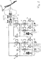
- Fig. 1 shows an embodiment of a motor vehicle brake system, which is suitable for carrying out the method according to the invention.
- the driver-actuated brake pedal 1 acts directly on an auxiliary-operated tandem master cylinder 2, in which therefore the operating force of the driver is amplified by a vacuum brake booster.
- the tandem master cylinder builds pressure in two essentially identical brake circuits I and II, which may be associated with the wheels both axle wise and diagonally.
- the brake fluid flows through isolation valves 3 and intake valves 6 into the wheel brakes or wheel brake cylinders 8, which build up a braking torque on the wheels. If the exhaust valves 7 are opened, then brake fluid can be discharged into the low-pressure accumulator 9.
- the hydraulic pumps 5 By activating the hydraulic pumps 5, a pressure build-up independent of the driver is made possible in one or more wheel brakes, for which purpose the electronic switching valves 4 are opened and the separating valves 3 are closed.
- the braking system shown is a regenerative braking system which allows recuperation of braking energy.
- an electric generator 10 which allows electric regenerative braking.
- the deceleration request of the driver is based on one with the brake pedal connected pedal angle sensor or a pedal travel sensor 11 detected and regulated the generator braking torque accordingly.
- the braking torque is built up only by the generator in a low deceleration region.
- a comfortable pedal feel for the driver can be provided by including in one or both of the low-pressure accumulators 9 a volume of brake fluid which would generate the corresponding deceleration in the wheel brakes.
- the method according to the invention can also be carried out with a braking system without an electric generator.
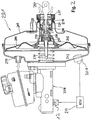
- FIG. 2 shows a master cylinder 208 with upstream vacuum brake booster 201, which is also referred to as a "booster".
- the vacuum brake booster 201 has a housing 205, which is divided into a working chamber 202 and a vacuum chamber 203. This is done by a movable partition 204, which is provided with an axially movable rubber membrane.
- a control hub 209 is arranged, whose function will be explained in more detail below.
- the power is output via a force output member 214, which is supported via a reaction disc 215 at a step 216.
- the control hub 209 extends through the housing 205 and is open to the atmosphere via a filter 217 axially.
- the working chamber 202 is sealed to the environment.
- the power transmission to the reaction disc 215 via a valve piston 219 which is clamped onto a ball head of a piston rod 207.
- the piston rod 207 extends through an air space 221 and communicates with an actuating pedal, not shown in connection.
- poppet valve 222 is inserted in the air space 221 in the air space 221.
- the poppet valve 222 is arranged so that it separates the air space 221 to the amplifier interior, as is the case in the rest position of the vacuum brake booster 201 shown here. In this rest position, the air supply to the working chamber 202 is shut off.
- there is a negative pressure in the working chamber 202 since the working chamber 202 is connected via openings with the vacuum chamber 203 and since the vacuum chamber 203 is connected via a vacuum port 10 with a vacuum source, not shown, preferably an electric vacuum pump.
- a sensor unit 206 With the aid of a sensor unit 206, the pressure in the vacuum chamber 203 is measured.
- any slight change in the pedal force causes an increase or decrease in the pressure difference on both sides of the partition 204 and causes an increase or reduction of the hydraulic pressure in the brake system and thus a controlled deceleration of the motor vehicle via the master cylinder 208.
- the maximum possible assist force of the vacuum brake booster 201 is given when the working chamber 202 is fully vented and atmospheric pressure prevails. This condition is called a trigger point. In the control point so the maximum pressure difference between the working chamber 202 and the vacuum chamber 203 is reached.
- a further increase in the force on the master cylinder piston, which adjoins the power output member 214, is only possible by an even greater pedal force of the driver, with the hydraulic pressure in the brake system only increases unreinforced. The result is that after exceeding the Aus Kunststoffens a further increase in the braking force requires a significantly increased force on the brake pedal.
- Defects of the pressure sensor 206 must not lead to an erroneous detection of the Aus Kunststoffens, and also a high pressure in the vacuum chamber (or lack of negative pressure) must be reliably detected. Therefore, preferably, a plausibility check of the pressure value measured by the sensor unit 206 is performed and possible defects of the sensor unit 206 or the vacuum brake booster 201 are detected, i. Sensor errors or failure of the vacuum brake booster 201 are reliably detected, whereby appropriate countermeasures and / or warning the driver can be made.
- the brake system may also include a tandem brake booster, which corresponds to two vacuum brake boosters connected in series and thus has two vacuum chambers and two working chambers. Also in these tandem brake boosters, the inventive method is applicable accordingly.
- the vacuum brake booster "consumes" some of its vacuum supply, i. the pressure in the vacuum chamber 203 increases.
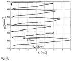
- Fig. 3 shows a diagram of the negative pressure in a vacuum brake booster in several successive Braking operations when no vacuum source is active.
- the pressure p in the vacuum chamber based on the atmospheric pressure is applied, ie at a negative pressure of 0 mbar no braking force support would be more, for example, a pressure p of -680 mbar or a vacuum of 680 mbar, the pressure in the vacuum chamber is 680 mbar below atmospheric pressure, in this example ensures optimal power assistance.
- the abscissa indicates the displacement of the master cylinder s, with a larger way a stronger brake actuation, ie corresponds to a larger pedal force or a higher pressure in the master cylinder.
- the arrow “Actuate” indicates the increase of the displacement path with stronger brake actuation, while the arrow “Release” indicates the release of the brake pedal by the driver.
- a pedal force or pedal angle sensor could be used on the brake pedal.
- the diagram shows that a stronger brake pedal actuation or a larger displacement travel of the master brake cylinder also leads to a correspondingly greater pressure increase in the vacuum chamber.
- the vacuum chamber In order to be able to provide an equal brake force boost at each braking, the vacuum chamber must therefore be connected to a vacuum source, e.g. a vacuum pump can be connected.
- the vacuum is generated alone or in addition via an electric vacuum pump (EVP).
- EMP electric vacuum pump
- the temporary shutdown of the internal combustion engine in order to reduce or avoid emissions alone by means of electric motor can (one speaks of "sailing operation"). So that in the sailing operation even after several braking maneuvers nor the full brake boosting is ensured, the electric vacuum pump is activated and evacuated the vacuum chamber.
- the electric vacuum pump In order to avoid a continuous operation of the electric vacuum pump, their control is preferably carried out as a hysteresis circuit with an upper and a lower switching point, wherein the signal of a vacuum sensor is evaluated.
- the vacuum pump control ensures that there is always a certain level of vacuum available as an energy source for the brake booster, even when the internal combustion engine is not in operation.
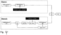
- Fig. 4 shows an embodiment of a method according to the invention for controlling an electric vacuum pump, the level 1 is not required in all embodiments of the invention.
- a pedal travel sensor detects the actuation travel s of the brake pedal and supplies the output signal to an evaluation unit, in particular a control unit of an electronically controlled brake system.
- the evaluation unit registers each pedal actuation, wherein the ascertained actuation path is summed up ⁇ s i and preferably converted into a vacuum consumption ⁇ p within the brake booster by means of a characteristic stored on the evaluation unit or a characteristic diagram. For example, this characteristic may have been previously measured in a calibration setup.
- the electric vacuum pump EPP is activated. This builds a negative pressure or reduces the pressure in the at least one vacuum chamber until a saturation pressure is established, which thus corresponds to the achievable under the present conditions vacuum.
- the vacuum level in the brake booster has been restored and the EPP can be deactivated again.
- the actuation integral ⁇ s i or the calculated vacuum consumption ⁇ p is reset to zero, after which the control cycle described begins again.
- the method described makes it possible to dispense with the use of a vacuum sensor for controlling the vacuum pump, which is associated with a reduced production costs and lower costs.
- consideration of brake pedal actuations that have already taken place can also be based on the output signals of a pedal angle sensor or a pedal force sensor.
- this may be e.g. a hydraulic pressure-volume map are determined.
- both a sensor for detecting the brake pedal angle and a sensor for detecting the hydraulic pressure in the master cylinder are present. Then both sizes can be used independently to control the electric vacuum pump, whereby a second fallback level is available. From a comparison of Master cylinder pressure with the brake pedal angle but can also be reached reaching the Ausreteticians the brake booster, so that, for example, a hydraulic pump can be activated for brake assistance.
- the safety concept of the braking system may require further monitoring measures and / or redundancies with regard to the control of a vacuum pump in order to ensure a minimum level of vacuum in all operating states of the braking system and thus a minimum braking capacity to meet legal or technical requirements.
- a redundant control of an electric vacuum pump takes place both with the method shown in level I and with the method shown in level II.
- a vacuum sensor detects the pressure p in at least one vacuum chamber of the brake booster. If the pressure p exceeds a first sub-atmospheric threshold p min , the remaining negative pressure thus causes a decrease in the amplification effect, then the electric vacuum pump is activated. Based on the atmosphere, the first vacuum threshold p min can be between -600 mbar and -750 mbar, for example.
- the electric vacuum pump reduces the pressure in the brake booster, wherein this one influenced by the pumping speed of the vacuum pump and the leakage rate of the vacuum chamber saturation pressure, ie a maximum achievable negative pressure approximates. As soon as the pressure p has dropped below a second negative pressure threshold p max , the electric vacuum pump is deactivated.
- the second vacuum threshold p max can be, for example, between -750 mbar and -850 mbar.
Landscapes
- Engineering & Computer Science (AREA)
- Transportation (AREA)
- Mechanical Engineering (AREA)
- Physics & Mathematics (AREA)
- Fluid Mechanics (AREA)
- Valves And Accessory Devices For Braking Systems (AREA)
- Braking Systems And Boosters (AREA)
- Regulating Braking Force (AREA)
Claims (15)
- Procédé pour le fonctionnement d'un système de freinage comprenant un servofrein qui est divisé par au moins une paroi de séparation mobile en au moins une chambre à dépression et au moins une chambre de travail, au moins une chambre à dépression étant connectée ou pouvant être connectée à une source de dépression pour produire une dépression, au moins un capteur qui détecte au moins une grandeur telle que la course et/ou l'angle et/ou la force d'actionnement d'une pédale de frein et/ou une pression de freinage qui est produite dans au moins un maître-cylindre de frein connecté au servofrein en fonction d'un actionnement de la pédale de frein, l'évaluation de la dépression restante dans au moins une chambre à dépression étant effectué à partir d'une considération des actionnements de la pédale de frein déjà effectués sur la base d'au moins l'une des grandeurs détectées, caractérisé en ce que la considération d'actionnements de la pédale de frein déjà effectués se produisant pour évaluer la dépression restante comprend une intégration ou une addition portant sur plusieurs valeurs successives dans le temps d'au moins l'une des grandeurs détectées.
- Procédé selon la revendication 1, caractérisé en ce qu'en fonction de, ou proportionnellement à, au moins l'une des grandeurs détectées, un couple de freinage est généré, en entraînant au moins un entraînement électrique du véhicule en tant que générateur et/ou en produisant une pression de freinage dans au moins un frein de roue du véhicule par un maître-cylindre de frein connecté au servofrein.
- Procédé selon la revendication 1 ou 2, caractérisé en ce que la dépression restante évaluée diminue avec l'augmentation de la somme effectivement déterminée ou l'augmentation de l'intégrale effectivement déterminée portant sur plusieurs valeurs successives dans le temps d'au moins l'une des grandeurs détectées, une courbe caractéristique ou un champ caractéristique étant de préférence évalué(e) pour l'étalonnage.
- Procédé selon l'une quelconque des revendications 1 à 3, caractérisé en ce qu'au moins une chambre à dépression est connectée à un groupe motopompe qui produit, en tant que source de dépression unique ou supplémentaire, lors de l'activation, une dépression dans la chambre à dépression, et en ce que le groupe motopompe est activé lorsque la somme ou l'intégrale, sur une ou plusieurs opérations d'actionnement de la pédale de frein, d'au moins l'une des grandeurs détectées, dépasse une valeur seuil d'actionnement.
- Procédé selon la revendication 4, caractérisé en ce que le groupe motopompe fonctionne pendant au moins une première période de temps.
- Procédé selon au moins l'une quelconque des revendications 1 à 5, caractérisé en ce qu'au moins une chambre à dépression est connectée à un capteur de pression et à un groupe motopompe, qui produit, en tant que source de dépression unique ou supplémentaire, lors de l'activation, une dépression dans la chambre à dépression, et en ce que le groupe motopompe est activé lorsque la pression mesurée dans la chambre à dépression dépasse une première valeur seuil de dépression.
- Procédé selon la revendication 6, caractérisé en ce que le groupe motopompe fonctionne tant que la pression mesurée dans la chambre à dépression ne passe pas en dessous d'une deuxième valeur seuil de dépression, la deuxième valeur seuil de dépression correspondant de préférence à une pression absolue inférieure à la première valeur seuil de dépression.
- Procédé selon au moins l'une quelconque des revendications 1 à 7, caractérisé en ce que la somme effectivement déterminée ou l'intégrale effectivement déterminée sur plusieurs valeurs successives dans le temps d'au moins l'une des grandeurs détectées est remise à la valeur zéro après que le groupe motopompe a fonctionné pendant au moins une première période de temps et/ou a fonctionné jusqu'à ce que la pression mesurée dans la chambre à dépression passe en dessous d'une deuxième valeur seuil de dépression.
- Procédé selon au moins l'une quelconque des revendications précédentes, caractérisé en ce que deux capteurs aptes à déterminer un actionnement de la pédale de frein sont prévus, en particulier un capteur pour détecter l'angle de la pédale de frein ou la course de la pédale de frein et/ou un capteur de distance au niveau du maître-cylindre de frein et/ou un capteur pour détecter la pression de freinage produite, et en ce qu'une comparaison des données de capteurs est effectuée.
- Procédé selon au moins l'une quelconque des revendications 6 à 9, caractérisé en ce qu'au moyen d'une source de pression supplémentaire pouvant être connectée au maître-cylindre de frein, il se produit un couple de freinage dans au moins un frein de roue du véhicule, lorsque le groupe motopompe a été actionné pendant au moins une deuxième période de temps sans que la pression dans la chambre à dépression ne passe en dessous d'une deuxième valeur seuil de dépression ou lorsque l'amplification du servofrein, déterminée à partir d'une comparaison des données de capteurs, passe en dessous d'une valeur seuil d'amplification prédéfinie.
- Procédé selon au moins l'une quelconque des revendications précédentes, caractérisé en ce qu'un avertissement du conducteur est généré lorsque la dépression restante évaluée dans au moins une chambre à dépression passe en dessous d'une valeur seuil minimale plus souvent qu'une valeur seuil de fréquence prédéterminée.
- Système de freinage pour un véhicule automobile, comprenant un servofrein qui est divisé par au moins une paroi de séparation en au moins une chambre à dépression et au moins une chambre de travail, au moins une chambre à dépression étant connectée ou pouvant être connectée à une source de dépression pour produire une dépression, un groupe motopompe en tant que source de dépression unique ou supplémentaire, au moins un maître-cylindre de frein connecté au servofrein, dans lesquels, en fonction d'un actionnement de la pédale de frein, une pression de freinage est générée, au moins un frein de roue connecté à un maître-cylindre de frein, au moins un capteur qui détecte au moins une grandeur telle que la course et/ou l'angle et/ou la force d'un actionnement de la pédale de frein et/ou une pression de freinage produite, caractérisé par un appareil de commande électronique qui est connecté à au moins l'un des capteurs pour détecter l'actionnement de la pédale de frein et/ou la pression de freinage et met en oeuvre un procédé selon au moins l'une quelconque des revendications précédentes.
- Système de freinage selon la revendication 12, caractérisé en ce qu'un capteur qui détecte l'angle de la pédale ou la course de la pédale d'un actionnement de la pédale de frein ainsi qu'un capteur pour détecter la pression de freinage produite sont prévus et l'appareil de commande électronique est connecté aux deux.
- Système de freinage selon la revendication 12 ou 13, caractérisé en ce qu'une pompe hydraulique pouvant être connectée à au moins un frein de roue est prévue.
- Utilisation d'un système de freinage selon au moins l'une quelconque des revendications 12 à 14 dans un véhicule automobile qui est entraîné par un moteur à combustion interne et/ou par au moins une machine électrique.
Applications Claiming Priority (2)
| Application Number | Priority Date | Filing Date | Title |
|---|---|---|---|
| DE102011007164 | 2011-04-11 | ||
| PCT/EP2012/056334 WO2012139979A1 (fr) | 2011-04-11 | 2012-04-05 | Procédé permettant de faire fonctionner un système de freinage |
Publications (2)
| Publication Number | Publication Date |
|---|---|
| EP2697106A1 EP2697106A1 (fr) | 2014-02-19 |
| EP2697106B1 true EP2697106B1 (fr) | 2018-10-24 |
Family
ID=45976348
Family Applications (1)
| Application Number | Title | Priority Date | Filing Date |
|---|---|---|---|
| EP12715043.1A Active EP2697106B1 (fr) | 2011-04-11 | 2012-04-05 | Procédé permettant de faire fonctionner un système de freinage |
Country Status (6)
| Country | Link |
|---|---|
| US (1) | US20140110994A1 (fr) |
| EP (1) | EP2697106B1 (fr) |
| KR (1) | KR20140023347A (fr) |
| CN (1) | CN103596825B (fr) |
| DE (1) | DE102012205713A1 (fr) |
| WO (1) | WO2012139979A1 (fr) |
Families Citing this family (16)
| Publication number | Priority date | Publication date | Assignee | Title |
|---|---|---|---|---|
| DE102012219193B4 (de) * | 2012-10-22 | 2026-02-19 | Robert Bosch Gmbh | Verfahren und Vorrichtung zum Betreiben eines Bremskraftverstärkers |
| DE102012023345B4 (de) | 2012-11-29 | 2021-03-04 | Zf Active Safety Gmbh | Bremssystem für ein Landfahrzeug und Verfahren zum Steuern des Bremssystems |
| DE102013009477A1 (de) * | 2013-06-06 | 2014-12-11 | GM Global Technology Operations LLC (n. d. Gesetzen des Staates Delaware) | Verfahren zur Steuerung eines Vakuumdrucks in einem Bremskraftverstärker eines Kraftfahrzeuges |
| US9260091B2 (en) * | 2013-07-16 | 2016-02-16 | Ford Global Technologies, Llc | Method and system for reducing vacuum consumption in a vehicle |
| FR3022205A1 (fr) * | 2014-06-17 | 2015-12-18 | Peugeot Citroen Automobiles Sa | Dispositif de controle de l'arret temporaire du moteur thermique d'un vehicule a dispositif d'aide au freinage et systeme d'arret temporaire |
| DE102015219944A1 (de) * | 2015-10-14 | 2017-04-20 | Ford Global Technologies, Llc | Verfahren zum Ansteuern einer elektrischen Vakuumpumpe eines Bremskraftverstärkers |
| DE102016218681B4 (de) * | 2016-09-28 | 2021-03-18 | Ford Global Technologies, Llc | Verfahren zum Betreiben eines hydraulischen Bremssystems eines Kraftfahrzeugs sowie hydraulisches Bremssystem für ein Kraftfahrzeug |
| DE102016220041A1 (de) * | 2016-10-14 | 2018-04-19 | Ford Global Technologies, Llc | Bremskraftverstärkersystem und Verfahren zur Unterstützung eines Bremsvorganges eines Kraftfahrzeuges |
| FR3063957B1 (fr) * | 2017-03-15 | 2019-04-05 | Renault S.A.S. | Procede de controle de fonctions automatiques d'un vehicule automobile |
| DE102019100788A1 (de) * | 2019-01-14 | 2020-07-16 | Wabco Gmbh | Verfahren zur Leckageüberwachung einer Druckluftanlage |
| CN112660095B (zh) * | 2019-10-15 | 2022-03-18 | 比亚迪股份有限公司 | 用于制动系统的液压装置、制动系统和车辆 |
| DE102020135055A1 (de) * | 2019-12-30 | 2021-07-01 | Hyundai Kefico Corporation | System und verfahren zum vorhersagen eines unterdrucks eines bremskraftverstärkers eines fahrzeugs |
| US11851039B2 (en) | 2019-12-30 | 2023-12-26 | Hyundai Motor Company | System and method for predicting negative pressure of brake booster of vehicle |
| CN111409616A (zh) * | 2020-03-06 | 2020-07-14 | 浙江零跑科技有限公司 | 一种新能源车用制动系统 |
| FR3122388B1 (fr) * | 2021-04-29 | 2023-03-17 | Psa Automobiles Sa | Procédé de diagnostic de plausibilité d’informations de mesure de pression dans un servofrein d’un système de freinage de véhicule |
| US12115904B2 (en) | 2023-02-13 | 2024-10-15 | Ford Global Techologies, Llc | Redundant system for brake light operation |
Family Cites Families (20)
| Publication number | Priority date | Publication date | Assignee | Title |
|---|---|---|---|---|
| JPS6261868A (ja) * | 1985-09-10 | 1987-03-18 | Toyota Motor Corp | 電動式負圧ポンプの駆動制御装置 |
| DE4413172C1 (de) * | 1994-04-15 | 1995-03-30 | Daimler Benz Ag | Verfahren zur fahrsituationsabhängigen Bestimmung der Auslöseempfindlichkeit eines automatischen Bremsvorganges für ein Kraftfahrzeug |
| DE19503451C1 (de) * | 1995-02-03 | 1996-05-15 | Daimler Benz Ag | Verfahren zur Überprüfung der Bremsanlage eines Fahrzeugs |
| DE19620540C2 (de) * | 1996-05-22 | 2001-06-13 | Lucas Automotive Gmbh | Elektronisch steuerbare Bremsanlage |
| US6033038A (en) * | 1998-06-22 | 2000-03-07 | General Motors Corporation | Brake control method having booster runout and pedal force estimation |
| DE69927928T2 (de) * | 1999-01-11 | 2006-07-27 | Toyota Jidosha K.K., Toyota | Bremssystem |
| US6557403B1 (en) * | 2000-01-07 | 2003-05-06 | Ford Global Technologies, Inc. | Lean engine with brake system |
| US7040719B2 (en) * | 2004-04-01 | 2006-05-09 | General Motors Corporation | Brake booster vacuum prediction algorithm and method of use therefor |
| WO2007082932A1 (fr) | 2006-01-20 | 2007-07-26 | Continental Teves Ag & Co. Ohg | Amplificateur de force de freinage basse pression, et procédé pour le faire fonctionner |
| DE102006027387B4 (de) * | 2006-06-13 | 2011-01-27 | Continental Automotive Gmbh | Bremsanlage für ein Hybrid-Kraftfahrzeug, zugehöriges Verfahren zu deren Funktionserhalt sowie zugehöriges Steuergerät |
| DE102007027768B4 (de) | 2006-06-22 | 2008-09-18 | Sauer-Danfoss Aps | Ein Flüssigkeitsregler und Verfahren zur Feststellung eines Fehlers in einem Flüssigkeitsregler |
| US8000861B2 (en) * | 2007-04-13 | 2011-08-16 | Advics Co., Ltd. | Braking control apparatus for vehicle |
| DE102008000628A1 (de) * | 2008-03-12 | 2009-09-17 | Robert Bosch Gmbh | Verfahren zum Erkennen von Veränderungen in der Steifigkeit eines hydraulischen Bremssystems |
| US8177309B2 (en) * | 2008-05-02 | 2012-05-15 | GM Global Technology Operations LLC | Braking booster system leak diagnostics |
| DE102008024293B4 (de) * | 2008-05-20 | 2022-03-03 | Bayerische Motoren Werke Aktiengesellschaft | Verfahren und Vorrichtung zum Erzeugen und Bereitstellen von Unterdruck, insbesondere in einem Kraftfahrzeug |
| DE102009011280A1 (de) * | 2009-03-02 | 2010-09-09 | Dr. Ing. H.C. F. Porsche Aktiengesellschaft | Verfahren zum Überprüfen der Funktion eines Bremssystems mit Bremskraftverstärker |
| DE102009027337B4 (de) * | 2009-06-30 | 2017-03-23 | Ford Global Technologies, Llc | Verfahren zum Schätzen des in einem Kraftfahrzeug-Bremskraftverstärker herrschenden Unterdrucks sowie Stopp-Start-Steuereinrichtung |
| CN102046945B (zh) * | 2009-08-21 | 2013-10-16 | 丰田自动车株式会社 | 发动机控制设备 |
| DE102010029185B4 (de) * | 2010-05-20 | 2022-03-17 | Bayerische Motoren Werke Aktiengesellschaft | Verfahren zum Betreiben eines Kraftfahrzeugs mit einer Unterdruckbremskraftverstärkungsvorrichtung |
| EP2505446B1 (fr) * | 2011-04-01 | 2013-12-18 | Honda Motor Co., Ltd. | Appareil de freinage véhiculaire |
-
2012
- 2012-04-05 WO PCT/EP2012/056334 patent/WO2012139979A1/fr not_active Ceased
- 2012-04-05 US US14/111,238 patent/US20140110994A1/en not_active Abandoned
- 2012-04-05 KR KR1020137029777A patent/KR20140023347A/ko not_active Withdrawn
- 2012-04-05 DE DE102012205713A patent/DE102012205713A1/de not_active Withdrawn
- 2012-04-05 CN CN201280028780.XA patent/CN103596825B/zh active Active
- 2012-04-05 EP EP12715043.1A patent/EP2697106B1/fr active Active
Non-Patent Citations (1)
| Title |
|---|
| None * |
Also Published As
| Publication number | Publication date |
|---|---|
| EP2697106A1 (fr) | 2014-02-19 |
| KR20140023347A (ko) | 2014-02-26 |
| CN103596825A (zh) | 2014-02-19 |
| CN103596825B (zh) | 2017-02-15 |
| US20140110994A1 (en) | 2014-04-24 |
| WO2012139979A1 (fr) | 2012-10-18 |
| DE102012205713A1 (de) | 2012-10-11 |
Similar Documents
| Publication | Publication Date | Title |
|---|---|---|
| EP2697106B1 (fr) | Procédé permettant de faire fonctionner un système de freinage | |
| DE112010001452B4 (de) | Bremssteuerungsvorrichtung | |
| EP0937620B1 (fr) | Procédé et dispositif de contrôle d' un système de freinage | |
| EP2668076B1 (fr) | Procédé pour surveiller la valeur de signal d'un capteur de dépression | |
| EP4610121A2 (fr) | Systeme hydraulique avec au moins deux circuits hydraulique et deux dispositifs d'alimentation en pression | |
| EP2668058B1 (fr) | Dispositif de commande pour un système de freinage de véhicule, système de freinage et procédé pour faire fonctionner un système de freinage de véhicule | |
| DE102014203866A1 (de) | Bremssteuerungsvorrichtung | |
| WO2018233854A1 (fr) | Système de freinage | |
| DE102013206324A1 (de) | Bremssystem für ein Fahrzeug und Verfahren zum Betreiben des Bremssystems | |
| DE102010038548B4 (de) | Bremssystem für ein Fahrzeug und Verfahren zum Betreiben eines Bremssystems für ein Fahrzeug | |
| EP4110665B1 (fr) | Système de freinage assisté par dépression à redondance | |
| WO2012167980A1 (fr) | Procédé permettant de faire fonctionner un système de freinage et système de freinage | |
| EP2688780A1 (fr) | Systèmes de freinage et procédé permettant de faire fonctionner un système de freinage d'un véhicule | |
| WO2002042138A1 (fr) | Procedes de commande d'un systeme de freinage electro-hydraulique | |
| DE112017001089B4 (de) | Bremsvorrichtung und Bremssteuerverfahren | |
| DE102012207553A1 (de) | Verfahren zur Plausibilisierung eines Vakuumsensors | |
| EP1501711B8 (fr) | Dispositif de freinage de vehicule a assistance au freinage hydraulique active et procede de commande associe | |
| WO2019129534A1 (fr) | Dispositif de traitement de signaux pour un véhicule comprenant un dispositif antiblocage, véhicule, procédé de traitement de signaux pour un véhicule, programme informatique et appareil de commande | |
| EP1989088B1 (fr) | Procede de gestion d'un système de freinage pour véhicule automobile | |
| EP2323880B1 (fr) | Procédé et dispositif d amplification hydraulique de la pression de freinage | |
| DE69833404T2 (de) | Manuelle Hinterbremssteuerung für eine elektro-hydraulische Bremsanlage | |
| WO2019129533A1 (fr) | Dispositif et procédé pour le calcul de pression de freinage, véhicule, programme informatique et appareil de commande | |
| DE102023207701B3 (de) | Leckageminimierung | |
| DE102024205841B3 (de) | Pumpenüberwachung mit Druckschwingungen | |
| WO2002062639A1 (fr) | Procede de regulation de la pression de freinage |
Legal Events
| Date | Code | Title | Description |
|---|---|---|---|
| PUAI | Public reference made under article 153(3) epc to a published international application that has entered the european phase |
Free format text: ORIGINAL CODE: 0009012 |
|
| 17P | Request for examination filed |
Effective date: 20131111 |
|
| AK | Designated contracting states |
Kind code of ref document: A1 Designated state(s): AL AT BE BG CH CY CZ DE DK EE ES FI FR GB GR HR HU IE IS IT LI LT LU LV MC MK MT NL NO PL PT RO RS SE SI SK SM TR |
|
| DAX | Request for extension of the european patent (deleted) | ||
| GRAP | Despatch of communication of intention to grant a patent |
Free format text: ORIGINAL CODE: EPIDOSNIGR1 |
|
| STAA | Information on the status of an ep patent application or granted ep patent |
Free format text: STATUS: GRANT OF PATENT IS INTENDED |
|
| INTG | Intention to grant announced |
Effective date: 20180618 |
|
| GRAS | Grant fee paid |
Free format text: ORIGINAL CODE: EPIDOSNIGR3 |
|
| RAP1 | Party data changed (applicant data changed or rights of an application transferred) |
Owner name: CONTINENTAL TEVES AG & CO. OHG |
|
| GRAA | (expected) grant |
Free format text: ORIGINAL CODE: 0009210 |
|
| STAA | Information on the status of an ep patent application or granted ep patent |
Free format text: STATUS: THE PATENT HAS BEEN GRANTED |
|
| AK | Designated contracting states |
Kind code of ref document: B1 Designated state(s): AL AT BE BG CH CY CZ DE DK EE ES FI FR GB GR HR HU IE IS IT LI LT LU LV MC MK MT NL NO PL PT RO RS SE SI SK SM TR |
|
| REG | Reference to a national code |
Ref country code: GB Ref legal event code: FG4D Free format text: NOT ENGLISH |
|
| REG | Reference to a national code |
Ref country code: CH Ref legal event code: EP |
|
| REG | Reference to a national code |
Ref country code: IE Ref legal event code: FG4D Free format text: LANGUAGE OF EP DOCUMENT: GERMAN |
|
| REG | Reference to a national code |
Ref country code: AT Ref legal event code: REF Ref document number: 1056312 Country of ref document: AT Kind code of ref document: T Effective date: 20181115 |
|
| REG | Reference to a national code |
Ref country code: DE Ref legal event code: R096 Ref document number: 502012013679 Country of ref document: DE |
|
| REG | Reference to a national code |
Ref country code: NL Ref legal event code: MP Effective date: 20181024 |
|
| REG | Reference to a national code |
Ref country code: LT Ref legal event code: MG4D |
|
| PG25 | Lapsed in a contracting state [announced via postgrant information from national office to epo] |
Ref country code: NL Free format text: LAPSE BECAUSE OF FAILURE TO SUBMIT A TRANSLATION OF THE DESCRIPTION OR TO PAY THE FEE WITHIN THE PRESCRIBED TIME-LIMIT Effective date: 20181024 |
|
| PG25 | Lapsed in a contracting state [announced via postgrant information from national office to epo] |
Ref country code: FI Free format text: LAPSE BECAUSE OF FAILURE TO SUBMIT A TRANSLATION OF THE DESCRIPTION OR TO PAY THE FEE WITHIN THE PRESCRIBED TIME-LIMIT Effective date: 20181024 Ref country code: LV Free format text: LAPSE BECAUSE OF FAILURE TO SUBMIT A TRANSLATION OF THE DESCRIPTION OR TO PAY THE FEE WITHIN THE PRESCRIBED TIME-LIMIT Effective date: 20181024 Ref country code: HR Free format text: LAPSE BECAUSE OF FAILURE TO SUBMIT A TRANSLATION OF THE DESCRIPTION OR TO PAY THE FEE WITHIN THE PRESCRIBED TIME-LIMIT Effective date: 20181024 Ref country code: PL Free format text: LAPSE BECAUSE OF FAILURE TO SUBMIT A TRANSLATION OF THE DESCRIPTION OR TO PAY THE FEE WITHIN THE PRESCRIBED TIME-LIMIT Effective date: 20181024 Ref country code: LT Free format text: LAPSE BECAUSE OF FAILURE TO SUBMIT A TRANSLATION OF THE DESCRIPTION OR TO PAY THE FEE WITHIN THE PRESCRIBED TIME-LIMIT Effective date: 20181024 Ref country code: BG Free format text: LAPSE BECAUSE OF FAILURE TO SUBMIT A TRANSLATION OF THE DESCRIPTION OR TO PAY THE FEE WITHIN THE PRESCRIBED TIME-LIMIT Effective date: 20190124 Ref country code: ES Free format text: LAPSE BECAUSE OF FAILURE TO SUBMIT A TRANSLATION OF THE DESCRIPTION OR TO PAY THE FEE WITHIN THE PRESCRIBED TIME-LIMIT Effective date: 20181024 Ref country code: NO Free format text: LAPSE BECAUSE OF FAILURE TO SUBMIT A TRANSLATION OF THE DESCRIPTION OR TO PAY THE FEE WITHIN THE PRESCRIBED TIME-LIMIT Effective date: 20190124 Ref country code: IS Free format text: LAPSE BECAUSE OF FAILURE TO SUBMIT A TRANSLATION OF THE DESCRIPTION OR TO PAY THE FEE WITHIN THE PRESCRIBED TIME-LIMIT Effective date: 20190224 |
|
| PG25 | Lapsed in a contracting state [announced via postgrant information from national office to epo] |
Ref country code: AL Free format text: LAPSE BECAUSE OF FAILURE TO SUBMIT A TRANSLATION OF THE DESCRIPTION OR TO PAY THE FEE WITHIN THE PRESCRIBED TIME-LIMIT Effective date: 20181024 Ref country code: GR Free format text: LAPSE BECAUSE OF FAILURE TO SUBMIT A TRANSLATION OF THE DESCRIPTION OR TO PAY THE FEE WITHIN THE PRESCRIBED TIME-LIMIT Effective date: 20190125 Ref country code: PT Free format text: LAPSE BECAUSE OF FAILURE TO SUBMIT A TRANSLATION OF THE DESCRIPTION OR TO PAY THE FEE WITHIN THE PRESCRIBED TIME-LIMIT Effective date: 20190224 Ref country code: RS Free format text: LAPSE BECAUSE OF FAILURE TO SUBMIT A TRANSLATION OF THE DESCRIPTION OR TO PAY THE FEE WITHIN THE PRESCRIBED TIME-LIMIT Effective date: 20181024 Ref country code: SE Free format text: LAPSE BECAUSE OF FAILURE TO SUBMIT A TRANSLATION OF THE DESCRIPTION OR TO PAY THE FEE WITHIN THE PRESCRIBED TIME-LIMIT Effective date: 20181024 |
|
| REG | Reference to a national code |
Ref country code: DE Ref legal event code: R097 Ref document number: 502012013679 Country of ref document: DE |
|
| PG25 | Lapsed in a contracting state [announced via postgrant information from national office to epo] |
Ref country code: CZ Free format text: LAPSE BECAUSE OF FAILURE TO SUBMIT A TRANSLATION OF THE DESCRIPTION OR TO PAY THE FEE WITHIN THE PRESCRIBED TIME-LIMIT Effective date: 20181024 Ref country code: IT Free format text: LAPSE BECAUSE OF FAILURE TO SUBMIT A TRANSLATION OF THE DESCRIPTION OR TO PAY THE FEE WITHIN THE PRESCRIBED TIME-LIMIT Effective date: 20181024 Ref country code: DK Free format text: LAPSE BECAUSE OF FAILURE TO SUBMIT A TRANSLATION OF THE DESCRIPTION OR TO PAY THE FEE WITHIN THE PRESCRIBED TIME-LIMIT Effective date: 20181024 |
|
| PG25 | Lapsed in a contracting state [announced via postgrant information from national office to epo] |
Ref country code: EE Free format text: LAPSE BECAUSE OF FAILURE TO SUBMIT A TRANSLATION OF THE DESCRIPTION OR TO PAY THE FEE WITHIN THE PRESCRIBED TIME-LIMIT Effective date: 20181024 Ref country code: SM Free format text: LAPSE BECAUSE OF FAILURE TO SUBMIT A TRANSLATION OF THE DESCRIPTION OR TO PAY THE FEE WITHIN THE PRESCRIBED TIME-LIMIT Effective date: 20181024 Ref country code: SK Free format text: LAPSE BECAUSE OF FAILURE TO SUBMIT A TRANSLATION OF THE DESCRIPTION OR TO PAY THE FEE WITHIN THE PRESCRIBED TIME-LIMIT Effective date: 20181024 Ref country code: RO Free format text: LAPSE BECAUSE OF FAILURE TO SUBMIT A TRANSLATION OF THE DESCRIPTION OR TO PAY THE FEE WITHIN THE PRESCRIBED TIME-LIMIT Effective date: 20181024 |
|
| PLBE | No opposition filed within time limit |
Free format text: ORIGINAL CODE: 0009261 |
|
| STAA | Information on the status of an ep patent application or granted ep patent |
Free format text: STATUS: NO OPPOSITION FILED WITHIN TIME LIMIT |
|
| 26N | No opposition filed |
Effective date: 20190725 |
|
| PG25 | Lapsed in a contracting state [announced via postgrant information from national office to epo] |
Ref country code: SI Free format text: LAPSE BECAUSE OF FAILURE TO SUBMIT A TRANSLATION OF THE DESCRIPTION OR TO PAY THE FEE WITHIN THE PRESCRIBED TIME-LIMIT Effective date: 20181024 |
|
| REG | Reference to a national code |
Ref country code: CH Ref legal event code: PL |
|
| REG | Reference to a national code |
Ref country code: BE Ref legal event code: MM Effective date: 20190430 |
|
| GBPC | Gb: european patent ceased through non-payment of renewal fee |
Effective date: 20190405 |
|
| PG25 | Lapsed in a contracting state [announced via postgrant information from national office to epo] |
Ref country code: LU Free format text: LAPSE BECAUSE OF NON-PAYMENT OF DUE FEES Effective date: 20190405 Ref country code: MC Free format text: LAPSE BECAUSE OF FAILURE TO SUBMIT A TRANSLATION OF THE DESCRIPTION OR TO PAY THE FEE WITHIN THE PRESCRIBED TIME-LIMIT Effective date: 20181024 |
|
| PG25 | Lapsed in a contracting state [announced via postgrant information from national office to epo] |
Ref country code: GB Free format text: LAPSE BECAUSE OF NON-PAYMENT OF DUE FEES Effective date: 20190405 Ref country code: CH Free format text: LAPSE BECAUSE OF NON-PAYMENT OF DUE FEES Effective date: 20190430 Ref country code: LI Free format text: LAPSE BECAUSE OF NON-PAYMENT OF DUE FEES Effective date: 20190430 |
|
| PG25 | Lapsed in a contracting state [announced via postgrant information from national office to epo] |
Ref country code: BE Free format text: LAPSE BECAUSE OF NON-PAYMENT OF DUE FEES Effective date: 20190430 |
|
| PG25 | Lapsed in a contracting state [announced via postgrant information from national office to epo] |
Ref country code: TR Free format text: LAPSE BECAUSE OF FAILURE TO SUBMIT A TRANSLATION OF THE DESCRIPTION OR TO PAY THE FEE WITHIN THE PRESCRIBED TIME-LIMIT Effective date: 20181024 |
|
| PG25 | Lapsed in a contracting state [announced via postgrant information from national office to epo] |
Ref country code: IE Free format text: LAPSE BECAUSE OF NON-PAYMENT OF DUE FEES Effective date: 20190405 |
|
| REG | Reference to a national code |
Ref country code: AT Ref legal event code: MM01 Ref document number: 1056312 Country of ref document: AT Kind code of ref document: T Effective date: 20190405 |
|
| PG25 | Lapsed in a contracting state [announced via postgrant information from national office to epo] |
Ref country code: AT Free format text: LAPSE BECAUSE OF NON-PAYMENT OF DUE FEES Effective date: 20190405 |
|
| PG25 | Lapsed in a contracting state [announced via postgrant information from national office to epo] |
Ref country code: CY Free format text: LAPSE BECAUSE OF FAILURE TO SUBMIT A TRANSLATION OF THE DESCRIPTION OR TO PAY THE FEE WITHIN THE PRESCRIBED TIME-LIMIT Effective date: 20181024 |
|
| PG25 | Lapsed in a contracting state [announced via postgrant information from national office to epo] |
Ref country code: MT Free format text: LAPSE BECAUSE OF FAILURE TO SUBMIT A TRANSLATION OF THE DESCRIPTION OR TO PAY THE FEE WITHIN THE PRESCRIBED TIME-LIMIT Effective date: 20181024 Ref country code: HU Free format text: LAPSE BECAUSE OF FAILURE TO SUBMIT A TRANSLATION OF THE DESCRIPTION OR TO PAY THE FEE WITHIN THE PRESCRIBED TIME-LIMIT; INVALID AB INITIO Effective date: 20120405 |
|
| PG25 | Lapsed in a contracting state [announced via postgrant information from national office to epo] |
Ref country code: MK Free format text: LAPSE BECAUSE OF FAILURE TO SUBMIT A TRANSLATION OF THE DESCRIPTION OR TO PAY THE FEE WITHIN THE PRESCRIBED TIME-LIMIT Effective date: 20181024 |
|
| REG | Reference to a national code |
Ref country code: DE Ref legal event code: R081 Ref document number: 502012013679 Country of ref document: DE Owner name: CONTINENTAL AUTOMOTIVE TECHNOLOGIES GMBH, DE Free format text: FORMER OWNER: CONTINENTAL TEVES AG & CO. OHG, 60488 FRANKFURT, DE Ref country code: DE Ref legal event code: R081 Ref document number: 502012013679 Country of ref document: DE Owner name: AUMOVIO GERMANY GMBH, DE Free format text: FORMER OWNER: CONTINENTAL TEVES AG & CO. OHG, 60488 FRANKFURT, DE |
|
| REG | Reference to a national code |
Ref country code: DE Ref legal event code: R081 Ref document number: 502012013679 Country of ref document: DE Owner name: CONTINENTAL AUTOMOTIVE TECHNOLOGIES GMBH, DE Free format text: FORMER OWNER: CONTINENTAL AUTOMOTIVE TECHNOLOGIES GMBH, 30165 HANNOVER, DE Ref country code: DE Ref legal event code: R081 Ref document number: 502012013679 Country of ref document: DE Owner name: AUMOVIO GERMANY GMBH, DE Free format text: FORMER OWNER: CONTINENTAL AUTOMOTIVE TECHNOLOGIES GMBH, 30165 HANNOVER, DE |
|
| PGFP | Annual fee paid to national office [announced via postgrant information from national office to epo] |
Ref country code: DE Payment date: 20250430 Year of fee payment: 14 |
|
| PGFP | Annual fee paid to national office [announced via postgrant information from national office to epo] |
Ref country code: FR Payment date: 20250425 Year of fee payment: 14 |
|
| REG | Reference to a national code |
Ref country code: DE Ref legal event code: R081 Ref document number: 502012013679 Country of ref document: DE Owner name: AUMOVIO GERMANY GMBH, DE Free format text: FORMER OWNER: CONTINENTAL AUTOMOTIVE TECHNOLOGIES GMBH, 30175 HANNOVER, DE |