EP2697117B1 - Ensemble châssis de base de sièges de passager - Google Patents
Ensemble châssis de base de sièges de passager Download PDFInfo
- Publication number
- EP2697117B1 EP2697117B1 EP13739341.9A EP13739341A EP2697117B1 EP 2697117 B1 EP2697117 B1 EP 2697117B1 EP 13739341 A EP13739341 A EP 13739341A EP 2697117 B1 EP2697117 B1 EP 2697117B1
- Authority
- EP
- European Patent Office
- Prior art keywords
- seat
- support structure
- base frame
- frame assembly
- coupled
- Prior art date
- Legal status (The legal status is an assumption and is not a legal conclusion. Google has not performed a legal analysis and makes no representation as to the accuracy of the status listed.)
- Active
Links
Images






Classifications
-
- B—PERFORMING OPERATIONS; TRANSPORTING
- B60—VEHICLES IN GENERAL
- B60N—SEATS SPECIALLY ADAPTED FOR VEHICLES; VEHICLE PASSENGER ACCOMMODATION NOT OTHERWISE PROVIDED FOR
- B60N2/00—Seats specially adapted for vehicles; Arrangement or mounting of seats in vehicles
- B60N2/005—Arrangement or mounting of seats in vehicles, e.g. dismountable auxiliary seats
- B60N2/01—Arrangement of seats relative to one another
-
- B—PERFORMING OPERATIONS; TRANSPORTING
- B60—VEHICLES IN GENERAL
- B60N—SEATS SPECIALLY ADAPTED FOR VEHICLES; VEHICLE PASSENGER ACCOMMODATION NOT OTHERWISE PROVIDED FOR
- B60N2/00—Seats specially adapted for vehicles; Arrangement or mounting of seats in vehicles
- B60N2/005—Arrangement or mounting of seats in vehicles, e.g. dismountable auxiliary seats
- B60N2/015—Attaching seats directly to vehicle chassis
-
- B—PERFORMING OPERATIONS; TRANSPORTING
- B60—VEHICLES IN GENERAL
- B60N—SEATS SPECIALLY ADAPTED FOR VEHICLES; VEHICLE PASSENGER ACCOMMODATION NOT OTHERWISE PROVIDED FOR
- B60N2/00—Seats specially adapted for vehicles; Arrangement or mounting of seats in vehicles
- B60N2/02—Seats specially adapted for vehicles; Arrangement or mounting of seats in vehicles the seat or part thereof being movable, e.g. adjustable
- B60N2/04—Seats specially adapted for vehicles; Arrangement or mounting of seats in vehicles the seat or part thereof being movable, e.g. adjustable the whole seat being movable
-
- B—PERFORMING OPERATIONS; TRANSPORTING
- B60—VEHICLES IN GENERAL
- B60N—SEATS SPECIALLY ADAPTED FOR VEHICLES; VEHICLE PASSENGER ACCOMMODATION NOT OTHERWISE PROVIDED FOR
- B60N2/00—Seats specially adapted for vehicles; Arrangement or mounting of seats in vehicles
- B60N2/68—Seat frames
-
- B—PERFORMING OPERATIONS; TRANSPORTING
- B64—AIRCRAFT; AVIATION; COSMONAUTICS
- B64D—EQUIPMENT FOR FITTING IN OR TO AIRCRAFT; FLIGHT SUITS; PARACHUTES; ARRANGEMENT OR MOUNTING OF POWER PLANTS OR PROPULSION TRANSMISSIONS IN AIRCRAFT
- B64D11/00—Passenger or crew accommodation; Flight-deck installations not otherwise provided for
- B64D11/06—Arrangements of seats, or adaptations or details specially adapted for aircraft seats
-
- B—PERFORMING OPERATIONS; TRANSPORTING
- B64—AIRCRAFT; AVIATION; COSMONAUTICS
- B64D—EQUIPMENT FOR FITTING IN OR TO AIRCRAFT; FLIGHT SUITS; PARACHUTES; ARRANGEMENT OR MOUNTING OF POWER PLANTS OR PROPULSION TRANSMISSIONS IN AIRCRAFT
- B64D11/00—Passenger or crew accommodation; Flight-deck installations not otherwise provided for
- B64D11/06—Arrangements of seats, or adaptations or details specially adapted for aircraft seats
- B64D11/0601—Arrangement of seats for non-standard seating layouts, e.g. seats staggered horizontally or vertically, arranged in an angled or fishbone layout, or facing in other directions than the direction of flight
-
- B—PERFORMING OPERATIONS; TRANSPORTING
- B64—AIRCRAFT; AVIATION; COSMONAUTICS
- B64D—EQUIPMENT FOR FITTING IN OR TO AIRCRAFT; FLIGHT SUITS; PARACHUTES; ARRANGEMENT OR MOUNTING OF POWER PLANTS OR PROPULSION TRANSMISSIONS IN AIRCRAFT
- B64D11/00—Passenger or crew accommodation; Flight-deck installations not otherwise provided for
- B64D11/06—Arrangements of seats, or adaptations or details specially adapted for aircraft seats
- B64D11/0602—Seat modules, i.e. seat systems including furniture separate from the seat itself
- B64D11/0604—Seat modules, i.e. seat systems including furniture separate from the seat itself including a bed, e.g. cocoon type passenger seat modules
-
- B—PERFORMING OPERATIONS; TRANSPORTING
- B64—AIRCRAFT; AVIATION; COSMONAUTICS
- B64D—EQUIPMENT FOR FITTING IN OR TO AIRCRAFT; FLIGHT SUITS; PARACHUTES; ARRANGEMENT OR MOUNTING OF POWER PLANTS OR PROPULSION TRANSMISSIONS IN AIRCRAFT
- B64D11/00—Passenger or crew accommodation; Flight-deck installations not otherwise provided for
- B64D11/06—Arrangements of seats, or adaptations or details specially adapted for aircraft seats
- B64D11/0639—Arrangements of seats, or adaptations or details specially adapted for aircraft seats with features for adjustment or converting of seats
-
- B—PERFORMING OPERATIONS; TRANSPORTING
- B64—AIRCRAFT; AVIATION; COSMONAUTICS
- B64D—EQUIPMENT FOR FITTING IN OR TO AIRCRAFT; FLIGHT SUITS; PARACHUTES; ARRANGEMENT OR MOUNTING OF POWER PLANTS OR PROPULSION TRANSMISSIONS IN AIRCRAFT
- B64D11/00—Passenger or crew accommodation; Flight-deck installations not otherwise provided for
- B64D11/06—Arrangements of seats, or adaptations or details specially adapted for aircraft seats
- B64D11/0648—Lower frame constructions
-
- B—PERFORMING OPERATIONS; TRANSPORTING
- B64—AIRCRAFT; AVIATION; COSMONAUTICS
- B64D—EQUIPMENT FOR FITTING IN OR TO AIRCRAFT; FLIGHT SUITS; PARACHUTES; ARRANGEMENT OR MOUNTING OF POWER PLANTS OR PROPULSION TRANSMISSIONS IN AIRCRAFT
- B64D11/00—Passenger or crew accommodation; Flight-deck installations not otherwise provided for
- B64D11/06—Arrangements of seats, or adaptations or details specially adapted for aircraft seats
- B64D11/0696—Means for fastening seats to floors, e.g. to floor rails
-
- Y—GENERAL TAGGING OF NEW TECHNOLOGICAL DEVELOPMENTS; GENERAL TAGGING OF CROSS-SECTIONAL TECHNOLOGIES SPANNING OVER SEVERAL SECTIONS OF THE IPC; TECHNICAL SUBJECTS COVERED BY FORMER USPC CROSS-REFERENCE ART COLLECTIONS [XRACs] AND DIGESTS
- Y02—TECHNOLOGIES OR APPLICATIONS FOR MITIGATION OR ADAPTATION AGAINST CLIMATE CHANGE
- Y02T—CLIMATE CHANGE MITIGATION TECHNOLOGIES RELATED TO TRANSPORTATION
- Y02T50/00—Aeronautics or air transport
- Y02T50/40—Weight reduction
Definitions
- the invention relates to support structures for passenger seats and furniture installed in a vehicle cabin.
- Common carriers such as passenger airlines, bus lines, train lines, and passenger vehicles frequently include business class seating in which a monument is placed around a portion of the passenger seat to offer privacy, stowage, and support for a table, and a video monitor. Because the cabins of such vehicles traditionally include seat tracks in the floor that are aligned with the longitudinal direction of the vehicle, installation of seating and furniture at an angle to such tracks, while also complying with all necessary safety regulations presents a challenge.
- a pallet or plinth on which the passenger seat and the monument are mounted has been used to connect the seat and monument to the seat tracks, but the design creates a floor level that is uneven with the cabin floor, thus presenting trip hazards for passengers moving about the cabin.
- GB 2405790 describes a single lower frame on three points for connecting the seat and monument to the seat tracks, but does not provide a way to connect a footrest or other structures that may be used in conjunction with the monument and passenger seat.
- Document US7837146 describes a base frame assembly comprising a main frame having a seat support structure with a seat fitting.
- the seat support structure is configured to approximate a width of the passenger seat.
- Document WO2004/083035 describes multi-component seating units adapted to mount directly to regular aircraft (or similar) seat tracks.
- the units may include base frames extended beyond the normal seat envelope to permit intersection of the frames with regular seat tracks in orientations other than simply with seats aligned longitudinally with the tracks.
- a base frame assembly for installing passenger seats, monuments, and other structures at an angle to the direction of seat tracks within a vehicle floor, in which the base frame assembly does significantly interfere with passenger foot space or present tripping hazards.
- Embodiments of the present invention include a base frame assembly for a passenger seat comprising the technical features according to claim 1.
- the seat support structure and the lateral support structure are integrally formed as a single panel, and may further include a plurality of kinematic fittings coupled to an upper surface of the single panel and configured to couple to the passenger seat.
- the seat support structure comprises a pair of spars coupled to opposing sides of a panel, and a beam coupled to an end of each spar and positioned adjacent a third side of the panel, and the lateral support structure comprises a beam coupled to an opposing end of each spar and positioned adjacent a fourth side of the panel.
- Each spar may be coupled to the beams with a bridge mounting configuration.
- a plurality of furniture fittings may be coupled to the beams, wherein each furniture fitting is configured to couple to the surrounding monument.
- the seat support structure comprises a plate
- the lateral support structure comprises a beam
- the seat support structure comprises a box frame, and a beam coupled to an end of the box frame, and the lateral support structure comprises a beam coupled to an opposing end of the box frame.
- Embodiments of the present invention also include a passenger seat module comprising a base frame assembly comprising a main frame comprising a seat support structure and a lateral support structure, wherein the lateral support structure comprises two seat fittings, and the seat support structure comprises one seat fitting, and a secondary frame pivotally coupled to the main frame, wherein the secondary frame comprises one seat fitting, a passenger seat mounted to the base frame assembly, wherein the passenger seat comprises a back configured to fold forward into a substantially horizontal position, and a monument comprising an upper portion and a lower portion, wherein the lower portion is mounted to the base frame assembly, and the upper portion is releasably attached to the lower portion.
- the lower portion may be configured to have a height of approximately 50.8-63.5 centimeters (20-25 inches).
- a second seat support structure may also be pivotally coupled to the lateral support structure.
- the lateral support structure may be configured to have a length that approximates a combined width of the passenger seat and the surrounding monument, and the seat support structure may be configured to approximate a width of the passenger seat.
- the described embodiments of the invention provide base frame assemblies for use with passenger seats and furniture. While the base frame assemblies are discussed for use with aircraft passenger seats, they are by no means so limited. Rather, the base frame assemblies may be used with other types of seats or structures of any type or otherwise as desired.
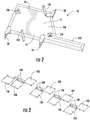
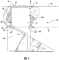
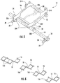
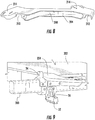
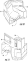
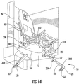
- FIGS 1-23 illustrate embodiments of a base frame assembly 10.
- the base frame assembly 10 comprises a main frame 12 and a secondary frame 14.
- the main frame 12 and/or the secondary frame 14 may be formed of aluminum, other metallic materials, plastic materials, composite materials, or other suitable materials that provide a sufficient strength and stiffness, particularly to avoid warpage effects.
- the main frame 12 includes a seat support structure 16 and a lateral support structure 18.
- the seat support structure 16 is configured to be positioned below at least a substantial portion of a passenger seat 20, such that the seat support structure 16 is configured to approximate a width of the passenger seat 20.
- the lateral support structure 18 is configured to have a length L that at least corresponds to a distance D between two seat tracks 22, 24 located in a cabin floor of an aircraft or other vehicle, and may further be configured to have a length L that exceeds the distance D between the two seat tracks 22, 24.
- the distance D approximates a width of the passenger seat 20.
- the distance D approximates a combined width of the passenger seat 20 and a surrounding monument 26.
- the lateral support structure 18 may be configured so that a central axis that corresponds to the direction of the length L is oriented generally perpendicular to a central axis of the two parallel seat tracks 22, 24.
- the lateral support structure 18 may be oriented in any suitable direction relative to the seat tracks 22, 24 that provides a suitable structural stability and stiffness to withstand warpage effects when the passenger seat 20 and the monument 26 are coupled to the base frame assembly 10, and the base frame assembly 10 is coupled to the seat tracks 22, 24.
- the entire main frame 12 is integrally formed so that the structures 16, 18 form a single panel 100.
- a U-shaped channel 102 may be coupled to the edges of the panel 100 to provide additional rigidity to the panel 100.
- the panel 100 and/or the channel 102 may be formed of aluminum, other metallic materials, plastic materials, composite materials, or other suitable materials that provide a sufficient strength and stiffness, particularly to avoid warpage effects.
- the panel 100 may have an inner honeycomb design to further minimize the weight of the panel 100.
- the inner honeycomb design may be covered by a skin having approximately a 2 mm thickness, so that the entire thickness of the panel is approximately 30 mm.
- any suitable panel structure, thickness, and weight may be used that provides a suitable structural stability and stiffness to withstand warpage effects when the passenger seat 20 and the monument 26 are coupled to the base frame assembly 10, and the base frame assembly 10 is coupled to the seat tracks 22, 24.
- At least two seat fittings 28 are attached to the panel 100 in the region that corresponds to the location of lateral support structure 18, and at least one seat fitting 30 is attached to the panel 100 in the region that corresponds to the seat support structure 16.
- the at least two seat fittings 28 may be positioned in any suitable location along the central axis of the lateral support structure 18 that aligns with the location of the seat tracks 22, 24, and the at least one seat fitting 30 may be positioned in any suitable location along the surface of the seat support structure 16 that aligns with the location of one of the seat tracks 22, 24.
- the seat fittings 28, 30 may be attached to the panel 100 via rivets, screws, or other suitable mechanical or chemical fasteners. The seat fittings 28, 30 are then attached to the seat tracks 22, 24 via studs 32.
- kinematic fittings 104 are attached to the seat support structure 16 and configured to couple to the passenger seat 20.
- the kinematic fittings 104 may be located in any suitable location on the seat support structure 16 that aligns with corresponding coupling locations on the passenger seat 20 when the passenger seat 20 is positioned in the desired location and orientation above the seat support structure 16.
- the kinematic fittings 104 may be attached to the panel 100 via rivets, screws, or other suitable mechanical or chemical fasteners.
- the passenger seat 20 may then be attached to the kinematic fittings 104 via rivets, screws, or other suitable mechanical or chemical fasteners.
- Furniture fittings 34 are attached to the lateral support structure 18 and/or seat support structure 16 and configured to couple to the surrounding monument 26.
- the furniture fittings 34 may be located in any suitable location that aligns with the corresponding coupling locations on the monument 26 when the monument 26 is positioned in the desired location and orientation above and/or adjacent the lateral support structure 18 and/or the seat support structure 16.
- the furniture fittings 34 may be attached to the panel 100 via rivets, screws, or other suitable mechanical or chemical fasteners.
- a panel 106 may be coupled to the panel 100 so that the base frame assembly 10 may be implemented in a staggered module, as shown in Figure 3 .
- the additional panel 106 is coupled to the panel 100 in a location so as to extend below a substantial portion of a second passenger seat 20 that is positioned adjacent the first passenger seat 20.
- any suitable arrangement between the panels 100 and 106 may be used as needed to achieve the desired staggered arrangement.
- the panel 106 may be formed of the same or different materials as panel 100, and may have a shape similar to that of the seat support structure 16 portion of the panel 100 or may have a different shape as needed to achieve a suitable structural stability and stiffness that will withstand warpage effects when the two passenger seats 20 and the monument 26 are coupled to the base frame assembly 10, and the base frame assembly 10 is coupled to the seat tracks 22, 24.
- the additional panel 106 may coupled to the panel 100 via a pivot coupling 108.
- the pivot coupling 108 is oriented generally perpendicular to the central axis of the seat tracks 22, 24 and generally parallel to a plane that crosses the seat tracks 22, 24. The orientation of the pivot coupling 108 effectively locks the panel 106 to the panel 100 when the base frame assembly 10 is coupled to the seat tracks 22, 24.
- main frame 12 By forming the main frame 12 as an integral panel 100, such a design would limit the panel size, thereby reducing weight and costs, and would provide a large area below the seat 20 to place all boxes (such as in-flight entertainment components, etc.) within easy access. In some embodiments, multiple panels 100 may be required for specific seat installation configurations.
- the entire main frame 12 is formed so that the seat support structure 16 is a separate structure from lateral support structure 18.
- the lateral support structure 18 may be a beam 200.
- the beam 200 may have dimensions of approximately 50 mm by approximately 40 mm.
- the beam 200 may be formed of aluminum, other metallic materials, plastic materials, composite materials, or other suitable materials, and may further have a rectangular, circular, square, elliptical, "I" or other suitable cross-sectional shape as needed to provide a sufficient strength and stiffness, particularly to avoid warpage effects when the passenger seat 20 and the monument 26 are coupled to the base frame assembly 10, and the base frame assembly 10 is coupled to the seat tracks 22, 24.
- the seat support structure 16 comprises a panel 202, a pair of spars 204, and a second beam 206.
- the second beam 206 may be formed of the same materials, shape, and components as the beam 200, or may be formed of different materials, shapes, and/or components as needed to achieve a suitable structural stability and stiffness that will withstand warpage effects when the two passenger seats 20 and the monument 26 are coupled to the base frame assembly 10, and the base frame assembly 10 is coupled to the seat tracks 22, 24.
- the panel 202 may be formed of aluminum, other metallic materials, plastic materials, composite materials, or other suitable materials, and may further have a diamond, square, rectangular, circular, or other suitable shape.
- the panel 202 may have an inner honeycomb design to further minimize the weight of the panel 202.
- the inner honeycomb design may be covered by a skin having approximately a 2 mm thickness, so that the entire thickness of the panel is approximately 40 mm.
- any suitable panel structure, thickness, and weight may be used that provides a suitable structural stability and stiffness to withstand warpage effects when the passenger seat 20 and the monument 26 are coupled to the base frame assembly 10, and the base frame assembly 10 is coupled to the seat tracks 22, 24.
- Each spar 204 includes a U-shaped channel 208 that is configured to receive an edge of the panel 202. Each spar 204 may be configured so that the ends of the channel 208 are deeper in order to reduce corner stress on the panel 202 by providing more support for the corners of the panel 202. Each spar 204 further includes a pair of recesses 210, 212 positioned at each end of the channel 208. The recess 210 is configured to fit around a portion of the beam 200, and the recess 212 is configured to fit around a portion of the beam 206.
- the main frame 12 is formed when the panel 202 is inserted within the channels 208 of the spars 204, the recesses 210 of each spar 204 are fitted around a portion of the beam 200 and coupled thereto, and the recesses 212 of each spar are fitted around a portion of the beam 206 and coupled thereto.
- the panel 202 may be held in place within the channels 208 of the spars 204 when the spars 204 are coupled to the beams 200, 206 or may be coupled directly to the spars 204 via rivets, screws, or other suitable mechanical or chemical fasteners.
- the recesses 210, 212 may be configured as bridge mounting connections, so that the spars 204 may be coupled to an upper half of the beams 200, 206 with a bridge mounting and screw so as to prevent any interference with the positioning of seat fittings 28, 30 along a lower half of the beams 200, 206, which is described in more detail below.
- the spars 204 may be attached to the beams 200, 206 via rivets, screws, or other suitable mechanical or chemical fasteners.
- each end of the spars 204 include a plurality of apertures 214 to allow for the passenger seat 20 to couple to the spars 204 in a variety of angles.
- the spars 204 may have a reversible design so that each spar 204 may be coupled to either side of the panel 202.
- the passenger seat 20 may then be attached to the apertures 214 via rivets, screws, or other suitable mechanical or chemical fasteners.
- At least two seat fittings 28 are attached to the beam 200, and at least one seat fitting 30 is attached to the beam 206.
- the at least two seat fittings 28 may be located in any suitable location along the beam 200 that aligns with the location of the seat tracks 22, 24, and the at least one seat fitting 30 may be located in any suitable location along the beam 206 that aligns with the location of one of the seat tracks 22, 24.
- the seat fittings 28, 30 may be coupled to a lower half of the beams 200, 206 with a bridge mounting and screw so as to prevent any interference with the positioning of the spars 204 and the furniture fittings 34 along the upper half of the beams 200, 206, which is described in more detail below.
- the seat fittings 28, 30 may be attached to the beams 200, 206 via rivets, screws, or other suitable mechanical or chemical fasteners. The seat fittings 28, 30 are then attached to the seat tracks 22, 24 via studs 32.
- the furniture fittings 34 are attached to the beams 200, 206 and configured to couple to the surrounding monument 26.
- the furniture fittings 34 may be located in any suitable location that aligns with the corresponding coupling locations on the monument 26 when the monument 26 is positioned in the desired location and orientation above and/or adjacent the beams 200, 206.
- the furniture fittings 34 may be coupled to the upper half of the beams 200, 206 with a bridge mounting and screw so as to prevent any interference with the positioning of seat fittings 28, 30 along the lower half of the beams 200, 206, which is described in more detail below.
- the furniture fittings 34 may be attached to the beams 200, 206 via rivets, screws, or other suitable mechanical or chemical fasteners.
- the bridge mounting connections of the spars 204, furniture fittings 34, and seat fittings 28, 30 are configured have an inner shape that substantially conforms to no more than one-half of the circumferential shape of the beams 200, 206.
- the rectangular shape of the beams 200, 206 and the fitted U-shape of the bridge mounting connections are configured to prevent rotation of the connections about the beams 200, 206.
- bridge mounting connections are configured to not to extend over more than one-half of the surface of the beams 200, 206
- the bridge mounting connections on the lower half of the beams 200, 206 may be positioned along the beams 200, 206 without overlapping or interfering with any of the bridge mounting connections positioned on the upper half of the beams 200, 206 and vice versa.
- the seat fittings 28, 30 may be connected to the beams 200, 206 in any location regardless of the coupling locations of the spars 204 and furniture fittings 34.
- a second seat support structure 16A may be coupled to the beam 200 so that the base frame assembly 10 may be implemented in a staggered module, as shown in Figure 6 .
- the second seat support structure 16A is coupled to the beam 200 in a location so as to extend below a substantial portion of a second passenger seat 20 that is positioned adjacent the first passenger seat 20.
- any suitable arrangement between the seat support structure 16, 16A and the beam 200 may be used as needed to achieve the desired staggered arrangement.
- the second seat support structure 16A may be formed of the same materials, shape, and components as the seat support structure 16, or may be formed of different materials, shapes, and/or components as needed to achieve a suitable structural stability and stiffness that will withstand warpage effects when the two passenger seats 20 and the monument 26 are coupled to the base frame assembly 10, and the base frame assembly 10 is coupled to the seat tracks 22, 24.
- the panel 202, spars 204, and beams 200, 206 By using the panel 202, spars 204, and beams 200, 206, such a design would limit the panel size, thereby reducing weight and costs, and would provide a large area below the seat 20 to place all boxes (such as in-flight entertainment components, etc.) within easy access.
- the single panel 202 and spars 204 may be used for all configurations and attachments to the beams 200, 206, thereby also simplifying production.
- the thicker dimension of the base frame assembly 10 i.e. when the beam 200 and/or the beam 202 has a dimension of 50 mm
- the entire main frame 12 is formed so that the seat support structure 16 is a separate structure from lateral support structure 18.
- the lateral support structure 18 may be a beam 300.
- the beam 300 may be formed of aluminum, other metallic materials, plastic materials, composite materials, or other suitable materials, and may further have a rectangular, circular, square, elliptical, "I" or other suitable cross-sectional shape as needed to provide a sufficient strength and stiffness, particularly to avoid warpage effects when the passenger seat 20 and the monument 26 are coupled to the base frame assembly 10, and the base frame assembly 10 is coupled to the seat tracks 22, 24.
- the seat support structure 16 comprises a plate 302, a pair of coupling projections 304, and a third coupling projection 306.
- the plate 302 may be formed of aluminum, other metallic materials, plastic materials, composite materials, or other suitable materials, and may further have a diamond, square, rectangular, circular, or other suitable shape.
- any suitable plate structure, thickness, and weight may be used that provides a suitable structural stability and stiffness to withstand warpage effects when the passenger seat 20 and the monument 26 are coupled to the base frame assembly 10, and the base frame assembly 10 is coupled to the seat tracks 22, 24.
- the pair of coupling projections 304 may be positioned on a lower surface 308 of the plate 302 in locations that are configured to couple to the beam 300, and may be coupled to the beam 300 via rivets, screws, or other suitable mechanical or chemical fasteners.
- At least two seat fittings 28 are attached to the beam 300, and at least one seat fitting 30 is attached to the coupling projection 306.
- the at least two seat fittings 28 may be located in any suitable location along the beam 300 that aligns with the location of the seat tracks 22, 24, and the at least one coupling projection 306 may be located in any suitable location along the lower surface 308 of the plate 302 that aligns with the location of one of the seat tracks 22, 24.
- the seat fittings 28, 30 may be attached to the beam 300 and the coupling projection 306 via rivets, screws, or other suitable mechanical or chemical fasteners.
- the seat fittings 28, 30 are then attached to the seat tracks 22, 24 via studs 32.
- a pair of sliding tracks 310 are attached to an upper surface 312 of the plate 302.
- the passenger seat 20 is then coupled directly to the sliding tracks 310. Inclusion of the sliding tracks 310 directly on the plate 302 may improve the sliding operation of the passenger seat 20.
- a tracking actuator 314 is also coupled to the plate 302 for suppression of the cross-piece.
- the surrounding monument 26 may be coupled directly to the plate 302 via any suitable mechanical or chemical fasteners.
- a second seat support structure 16A may be coupled to a second beam 300A so that the base frame assembly 10 may be implemented in a staggered module, as shown in Figure 15 .
- the beam 300A may be positioned forward of the beam 300, and the second seat support structure 16A may be coupled to the beam 300A in an orientation that mirrors the positioning of the seat support structure 16 and beam 300.
- the seat support structure 16 is located aft and to the right end of the beam 300, and the seat support structure 16A is located forward and to the left end of the beam 300A.
- any suitable arrangement between the seat support structure 16, 16A and the beams 300, 300A may be used as needed to achieve the desired staggered arrangement, including but not limited to having both seat support structure 16, 16A coupled to the beam 300.
- the seat support structure 16, 16A may be connected directly to the seat tracks 22, 24 without the use of the beams 300, 300A.
- the second seat support structure 16A may be formed of the same materials, shape, and components as the seat support structure 16, or may be formed of different materials, shapes, and/or components as needed to achieve a suitable structural stability and stiffness that will withstand warpage effects when the two passenger seats 20 and the monument 26 are coupled to the base frame assembly 10, and the base frame assembly 10 is coupled to the seat tracks 22, 24.
- the plate 302 and beam 300 By using the plate 302 and beam 300, such a design would limit the plate size, thereby reducing weight and costs.
- the boxes (such as in-flight entertainment components, etc.) may be placed below the seat area, but access to the boxes below the plate 302 may require removal of armrests and/or a rear panel.
- multiple plates 302 may be required for specific seat installation configurations, and large leg and beam configurations could increase the complexity of production.
- the entire main frame 12 is formed so that the seat support structure 16 is a separate structure from lateral support structure 18.
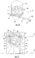
- the lateral support structure 18 may be a beam 400.
- the beam 400 may be formed of aluminum, other metallic materials, plastic materials, composite materials, or other suitable materials, and may further have a rectangular, circular, square, elliptical, "I" or other suitable cross-sectional shape as needed to provide a sufficient strength and stiffness, particularly to avoid warpage effects when the passenger seat 20 and the monument 26 are coupled to the base frame assembly 10, and the base frame assembly 10 is coupled to the seat tracks 22, 24.
- the seat support structure 16 comprises a box frame 402, and a second beam 404.
- the second beam 404 may be formed of the same materials, shape, and components as the beam 400, or may be formed of different materials, shapes, and/or components as needed to achieve a suitable structural stability and stiffness that will withstand warpage effects when the two passenger seats 20 and the monument 26 are coupled to the base frame assembly 10, and the base frame assembly 10 is coupled to the seat tracks 22, 24.
- the box frame 402 may be formed of aluminum, other metallic materials, plastic materials, composite materials, or other suitable materials, and may further have a diamond, square, rectangular, circular, or other suitable shape.
- any suitable box frame structure, thickness, and weight may be used that provides a suitable structural stability and stiffness to withstand warpage effects when the passenger seat 20 and the monument 26 are coupled to the base frame assembly 10, and the base frame assembly 10 is coupled to the seat tracks 22, 24.
- Coupling projections 406 may be positioned along the edges of the box frame 402 in locations that are configured to couple to the beams 400, 404, and may be coupled to the beams 400, 404 via rivets, screws, or other suitable mechanical or chemical fasteners.
- At least two seat fittings 28 are attached to the beam 400, and at least one seat fitting 30 is attached to the beam 404.
- the at least two seat fittings 28 may be located in any suitable location along the beam 400 that aligns with the location of the seat tracks 22, 24, and the at least one seat fitting 30 may be located in any suitable location along the beam 404 that aligns with the location of one of the seat tracks 22, 24.
- the seat fittings 28, 30 may be attached to the beams 400, 404 via rivets, screws, or other suitable mechanical or chemical fasteners.
- the seat fittings 28, 30 are then attached to the seat tracks 22, 24 via studs 32.
- the passenger seat 20 is then attached to the box frame 402 via any suitable mechanical fasteners in a manner that will withstand warpage effects when the passenger seat 20 and the monument 26 are coupled to the base frame assembly 10, and the base frame assembly 10 is coupled to the seat tracks 22, 24.
- Furniture fittings 34 are attached to the beams 400, 404 and configured to couple to the surrounding monument 26.
- the furniture fittings 34 may be located in any suitable location that aligns with the corresponding coupling locations on the monument 26 when the monument 26 is positioned in the desired location and orientation above and/or adjacent the beams 400, 404.
- the furniture fittings 34 may be coupled to the beams 400, 404 via any suitable mechanical or chemical fasteners.
- a second seat support structure 16A may be coupled to an additional beam 400A so that the base frame assembly 10 may be implemented in a staggered module, as shown in Figure 20 .
- the beam 400A may be positioned forward of the beam 400, and the second seat support structure 16A may be coupled to the beam 400A in an orientation that mirrors the positioning of the seat support structure 16 and beam 400.
- the seat support structure 16 is located aft and to the left end of the beam 400, and the seat support structure 16A is located forward and to the right end of the beam 400A.
- the second seat support structure 16A may be formed of the same materials, shape, and components as the seat support structure 16, or may be formed of different materials, shapes, and/or components as needed to achieve a suitable structural stability and stiffness that will withstand warpage effects when the two passenger seats 20 and the monument 26 are coupled to the base frame assembly 10, and the base frame assembly 10 is coupled to the seat tracks 22, 24.
- box frame 402 and the beams 400, 404 such a design would limit the frame size, thereby reducing weight and costs, and would provide a large area below the seat 20 to place all boxes (such as in-flight entertainment components, etc.) within easy access.
- the single box frame 402 may be used for all configurations and attachments to the beams 400, 404, thereby also simplifying production. In some embodiments, it will be necessary to ensure that the box frame 402 design is sufficiently rigid, particularly to avoid warpage effects when the passenger seat 20 and the monument 26 are coupled to the base frame assembly 10, and the base frame assembly 10 is coupled to the seat tracks 22, 24. Also, multiple kinematic fittings may be required for specific seat installation configurations.
- the secondary frame 14 may be positioned adjacent the seat support structure 16 and coupled to a portion of the lateral support structure 18 via a pivot coupling 36, as shown in Figure 1 .
- the secondary frame 14 is configured to be positioned below at least a substantial portion of a footrest 38.
- the secondary frame 14 further comprises at least one seat fitting 50 that is positioned in any suitable location along the surface of the secondary frame that aligns with the location of one of the seat tracks 22, 24.
- the seat fitting 50 may be attached to the secondary frame 14 via rivets, screws, or other suitable mechanical or chemical fasteners. The seat fitting 50 is then attached to one of the seat tracks 22, 24 via studs 32.
- the pivot coupling 36 is oriented generally perpendicular to the central axis of the seat tracks 22, 24 and generally parallel to a plane crossing the seat tracks 22, 24.
- the orientation of the pivot coupling 36 effectively locks the secondary frame 14 to the main frame 12 when the base frame assembly 10 coupled to the seat tracks 22, 24.
- any suitable coupling arrangement between the main frame 12 and the secondary frame 14 may be used as needed to achieve a suitable structural stability and stiffness that will withstand warpage effects when the passenger seat 20 and the monument 26 are coupled to the base frame assembly 10, and the base frame assembly 10 is coupled to the seat tracks 22, 24.
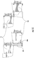
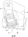
- a passenger seat module comprising the passenger seat 20, the surrounding monument 26, and the base frame assembly 10 may be subdivided into an upper part 40 and a lower part 42, as illustrated in Figures 21-23 .
- the upper part 40 comprises a portion of the monument 26 that is configured to be positioned proximate a back 44 of the passenger seat 20.
- the lower part 42 comprises the passenger seat 20, the base frame assembly 10, and the portion of the monument 26 that is configured to be positioned proximate a lower portion 46 of the passenger seat 20.
- the monument 26 may be divided horizontally at a height that is approximately 20-25 inches from the cabin floor.
- the back 44 of the passenger seat 20 folds down to minimize the height of the lower part 42.
- the upper part 40 comprises a plurality of coupling projections 48 that are configured to couple to corresponding coupling receptacles on the lower part 42.
Landscapes
- Engineering & Computer Science (AREA)
- Aviation & Aerospace Engineering (AREA)
- Transportation (AREA)
- Mechanical Engineering (AREA)
- Seats For Vehicles (AREA)
Claims (14)
- Ensemble formant cadre de base destiné à un siège passager et une construction environnante (26) montée sur l'ensemble formant cadre de base, ledit ensemble formant cadre de base comprenant :- un siège passager (20),- un cadre principal (12) comprenant une structure de support de siège (16) comprenant une fixation de siège pour ledit siège passager (20) et la structure de support de siège (16) étant conçue pour avoir approximativement la largeur du siège passager (20),- ledit cadre principal (12) comprenant en outre une structure de support latérale (18), la structure de support latérale (18) comprenant deux fixations de siège (28) destinées audit siège passager (20),ladite structure de support latérale (18) étant conçue pour avoir une longueur (L) qui est approximativement égale à la largeur combinée du siège passager (20) et de la construction environnante (26), la direction de la longueur (L) étant orientée d'une manière générale perpendiculairement à un axe central des rails de siège (22, 24),
caractérisé en ce que ledit ensemble de cadre de base (10) comprend en outre :- un cadre secondaire (14) accouplé de manière pivotante au cadre principal (12), le cadre secondaire (14) comprenant une fixation de siège (50) destinée audit siège passager (20), l'accouplement à pivotement (36) étant orienté d'une manière générale perpendiculairement à l'axe central des rails de siège (22, 24) et d'une manière générale parallèlement à un plan coupant les rails de siège (22, 24) lorsque l'ensemble formant cadre de base (10) est accouplé aux rails de siège (22,24). - Ensemble formant cadre de base selon la revendication 1, caractérisé en ce qu'il comprend en outre une deuxième structure de support de siège (16A) accouplée de manière pivotante à la structure de support latérale (18).
- Ensemble formant cadre de base selon la revendication 1, caractérisé en ce que la structure de support de siège (16) et la structure de support latérale (18) sont formées d'une seule pièce sous la forme d'un panneau unique.
- Ensemble formant cadre de base selon la revendication 3, caractérisé en ce qu'il comprend en outre une pluralité de fixations cinématiques accouplées à une surface supérieure du panneau unique et conçues pour s'accoupler au siège passager (20) .
- Ensemble formant cadre de base selon la revendication 1, caractérisé en ce que la structure de support de siège (16) comprend une paire de longerons accouplés à des côtés opposés d'un panneau, et une poutre accouplée à une extrémité de chaque longeron et positionnée de manière adjacente à un troisième côté du panneau.
- Ensemble formant cadre de base selon la revendication 5, caractérisé en ce que la structure de support latérale (18) comprend une poutre accouplée à une extrémité opposée de chaque longeron et positionnée de manière adjacente à un quatrième côté du panneau.
- Ensemble formant cadre de base selon la revendication 1, caractérisé en ce que la structure de support de siège (16) comprend une plaque et la structure de support latérale (18) comprend une poutre.
- Ensemble formant cadre de base selon la revendication 7, caractérisé en ce qu'il comprend en outre une paire de rails coulissantes accouplées à une surface supérieure de la plaque et conçues pour s'accoupler au siège passager (20).
- Ensemble formant cadre de base selon la revendication 1, caractérisé en ce que la structure de support de siège (16) comprend un cadre en caisson et une poutre accouplée à une extrémité du cadre en caisson.
- Ensemble formant cadre de base selon la revendication 9, caractérisé en ce que la structure de support latérale (18) comprend une poutre accouplée à une extrémité opposée du cadre en caisson.
- Module de siège passager, caractérisé en ce qu'il comprend :(a) un ensemble formant cadre de base selon l'une quelconque des revendications précédentes,le siège passager comprenant un dossier conçu pour se plier vers l'avant jusque dans une position sensiblement horizontale ; et
la construction (26) comprenant une partie supérieure et une partie inférieure, la partie inférieure étant montée sur l'ensemble formant cadre de base et la partie supérieure étant fixée de manière amovible à la partie inférieure. - Module de siège passager selon la revendication 11, caractérisé en ce que la partie inférieure est conçue pour avoir une hauteur d'environ 50,8 à 63,5 centimètres.
- Module de siège passager selon la revendication 11, caractérisé en ce qu'il comprend en outre une deuxième structure de support de siège (16A) accouplée de manière pivotante à la structure de support latérale (18).
- Module de siège passager selon la revendication 11, caractérisé en ce que la structure de support latérale (18) est conçue pour avoir une longueur qui est approximativement égale à la largeur combinée du siège passager et de la construction environnante (26), et la structure de support de siège (16) est conçue pour être approximativement égale à la largeur du siège passager (20).
Priority Applications (1)
| Application Number | Priority Date | Filing Date | Title |
|---|---|---|---|
| EP18159172.8A EP3348480B1 (fr) | 2012-07-06 | 2013-07-08 | Ensemble cadre de base pour sièges passagers |
Applications Claiming Priority (2)
| Application Number | Priority Date | Filing Date | Title |
|---|---|---|---|
| US201261668511P | 2012-07-06 | 2012-07-06 | |
| PCT/IB2013/055583 WO2013144935A2 (fr) | 2012-07-06 | 2013-07-08 | Ensemble châssis de base de sièges de passager |
Related Child Applications (2)
| Application Number | Title | Priority Date | Filing Date |
|---|---|---|---|
| EP18159172.8A Division EP3348480B1 (fr) | 2012-07-06 | 2013-07-08 | Ensemble cadre de base pour sièges passagers |
| EP18159172.8A Division-Into EP3348480B1 (fr) | 2012-07-06 | 2013-07-08 | Ensemble cadre de base pour sièges passagers |
Publications (2)
| Publication Number | Publication Date |
|---|---|
| EP2697117A2 EP2697117A2 (fr) | 2014-02-19 |
| EP2697117B1 true EP2697117B1 (fr) | 2019-08-28 |
Family
ID=48986182
Family Applications (2)
| Application Number | Title | Priority Date | Filing Date |
|---|---|---|---|
| EP13739341.9A Active EP2697117B1 (fr) | 2012-07-06 | 2013-07-08 | Ensemble châssis de base de sièges de passager |
| EP18159172.8A Active EP3348480B1 (fr) | 2012-07-06 | 2013-07-08 | Ensemble cadre de base pour sièges passagers |
Family Applications After (1)
| Application Number | Title | Priority Date | Filing Date |
|---|---|---|---|
| EP18159172.8A Active EP3348480B1 (fr) | 2012-07-06 | 2013-07-08 | Ensemble cadre de base pour sièges passagers |
Country Status (4)
| Country | Link |
|---|---|
| US (1) | US9796296B2 (fr) |
| EP (2) | EP2697117B1 (fr) |
| JP (2) | JP6294875B2 (fr) |
| WO (1) | WO2013144935A2 (fr) |
Families Citing this family (28)
| Publication number | Priority date | Publication date | Assignee | Title |
|---|---|---|---|---|
| USRE47872E1 (en) | 2011-07-11 | 2020-02-25 | Molon Labe Llc | Slider seat for aircraft |
| GB201217319D0 (en) | 2012-09-27 | 2012-11-14 | Acumen Design Associates Ltd | Aircraft passenger seating arrangement |
| DE102013103440A1 (de) * | 2013-04-05 | 2014-10-09 | Recaro Aircraft Seating Gmbh & Co. Kg | Flugzeugsitzvorrichtung |
| GB2516433B (en) * | 2013-07-19 | 2016-02-17 | British Airways Plc | Aircraft passenger seat fixing system |
| DE102013219616A1 (de) * | 2013-09-27 | 2015-04-02 | Lufthansa Technik Ag | Bodenanbindungsbaugruppe sowie Flugzeugsitz |
| USD733442S1 (en) | 2014-03-25 | 2015-07-07 | Acumen Design Associates Limited | Aircraft passenger seating arrangement |
| DE102014104915A1 (de) * | 2014-04-07 | 2015-10-08 | Recaro Aircraft Seating Gmbh & Co. Kg | Flugzeugsitzrahmenvorrichtung |
| US10556691B2 (en) * | 2015-11-25 | 2020-02-11 | The Boeing Company | Seat tracks with composite frames |
| DE102016110000B4 (de) * | 2016-05-31 | 2024-09-05 | Airbus Operations Gmbh | Sitzanordnung für eine Kabine eines Transportmittels sowie ein Transportmittel mit einer derartigen Sitzanordnung in einer Kabine |
| US10569881B2 (en) | 2016-10-18 | 2020-02-25 | Molon Labe, Llc | Staggered aircraft seat assembly |
| JP2018176772A (ja) * | 2017-04-03 | 2018-11-15 | 株式会社ジャムコ | 座席ユニット及びその取付け方法 |
| JP7300035B2 (ja) * | 2017-04-03 | 2023-06-28 | 株式会社ジャムコ | 座席ユニット及びその取付け方法 |
| USD840701S1 (en) | 2017-10-18 | 2019-02-19 | Molon Labe, Llc | Staggered aircraft seats |
| USD850177S1 (en) | 2017-12-15 | 2019-06-04 | Molon Labe, Llc | Aircraft seat armrests |
| USD867775S1 (en) | 2018-04-03 | 2019-11-26 | Molon Labe, Llc | Set of multilevel aircraft seat armrests |
| CN113272225B (zh) * | 2018-10-31 | 2024-03-01 | 赛峰座椅美国有限责任公司 | 弯曲管座椅结构 |
| USD936383S1 (en) | 2019-08-01 | 2021-11-23 | Molon Labe, Llc | Staggered aircraft seat assembly |
| USD924043S1 (en) | 2019-08-22 | 2021-07-06 | Molon Labe, Llc | Aircraft wheelchair accommodating seat assembly |
| FR3102753B1 (fr) * | 2019-10-31 | 2022-05-06 | Safran Seats | Palette support pour une unite de siege d'avion |
| US11530042B2 (en) | 2020-04-24 | 2022-12-20 | Ami Industries, Inc. | Passenger seat assembly with integrated cabin attendant seat |
| WO2021247011A1 (fr) * | 2020-06-02 | 2021-12-09 | Safran Seats Santa Maria Llc | Accessoire de mobilier modulaire monté sur canal |
| FR3112514B1 (fr) | 2020-07-16 | 2023-11-10 | Safran Seats | Structure de coque a double jupes pour unite de siege |
| FR3112528B1 (fr) | 2020-07-16 | 2022-08-12 | Safran Seats | Unite de siege munie d'une structure basse de siege de type tubulaire |
| CA3200629A1 (fr) * | 2020-12-01 | 2022-06-09 | Mark Robert Hacker | Module de siege d'aeronef |
| DE102021110957A1 (de) * | 2021-04-28 | 2022-11-03 | Recaro Aircraft Seating Gmbh & Co. Kg | Flugzeugsitzanordnung |
| US12312016B2 (en) | 2022-12-30 | 2025-05-27 | Victor Manuel Chavez Vazquez | Retrofitted bus with improved passenger experience |
| EP4484286A1 (fr) * | 2023-06-28 | 2025-01-01 | Safran Seats | Unité de base |
| WO2025101657A1 (fr) * | 2023-11-06 | 2025-05-15 | Victor Manuel Chavez Vazquez | Bus modernisé à expérience de passager améliorée |
Family Cites Families (24)
| Publication number | Priority date | Publication date | Assignee | Title |
|---|---|---|---|---|
| US4382628A (en) * | 1980-08-25 | 1983-05-10 | The Boeing Company | Staggered seats in seating units for passenger compartments |
| US5553923A (en) * | 1993-12-08 | 1996-09-10 | Weber Aircraft, Inc. | Base frame for an aircraft seat |
| JPH0740255U (ja) * | 1993-12-27 | 1995-07-18 | アラコ株式会社 | 車両用シート |
| US5509722A (en) * | 1994-04-15 | 1996-04-23 | Burns Aerospace Corporation | Convertible passenger seat assembly and grouping of passenger seat assemblies |
| GB9706650D0 (en) * | 1997-04-02 | 1997-05-21 | Virgin Atlantic Airways Ltd | A seat |
| US6086018A (en) * | 1997-12-09 | 2000-07-11 | Mcdonnell Douglas Corporation | Interlocking assembly system for an aircraft cabin |
| US6227489B1 (en) * | 1998-05-15 | 2001-05-08 | Koito Industries, Ltd. | Aircraft seat apparatus |
| GB2406269B (en) | 2001-08-09 | 2005-10-05 | Virgin Atlantic Airways Ltd | A seat with a motorised reclining backrest |
| CA2581738C (fr) * | 2001-08-09 | 2009-04-14 | Virgin Atlantic Airways Limited | Systeme de sieges et unite d'accueil de passagers pour vehicule |
| US6644738B2 (en) * | 2001-11-21 | 2003-11-11 | B E Aerospace, Inc. | Aircraft passenger seat frame construction |
| US6817673B2 (en) * | 2002-04-17 | 2004-11-16 | Lear Corporation | Vehicle seat assembly |
| JP2006513916A (ja) * | 2003-03-18 | 2006-04-27 | ウェバー エアクラフト エルピー | 座席装着システムおよび方法 |
| US6802568B1 (en) * | 2003-04-28 | 2004-10-12 | Be Aerospace, Inc. | Segmented beam aircraft passenger seat |
| JP4214856B2 (ja) * | 2003-07-17 | 2009-01-28 | マツダ株式会社 | シート装置 |
| KR20060120000A (ko) * | 2003-10-06 | 2006-11-24 | 비이 에어로스페이스 인코포레이티드 | 머리 받침 지지 조립체 |
| GB0426527D0 (en) * | 2004-12-02 | 2005-01-05 | James Park Associates Ltd | Aircraft seat supporting structure |
| US20090114794A1 (en) * | 2005-01-14 | 2009-05-07 | Telezygology, Inc. | Securing Systems |
| DE102006040059A1 (de) * | 2006-08-26 | 2008-02-28 | Recaro Aircraft Seating Gmbh & Co. Kg | Strukturrahmen |
| FR2920011B1 (fr) * | 2007-08-16 | 2010-02-12 | Airbus | Siege pivotant destine a un aeronef et ensemble de tels sieges |
| GB0903744D0 (en) * | 2009-03-04 | 2009-04-15 | Virgin Atlantic Airways Ltd | A seating insallation for a passenger vehicle |
| US20100314494A1 (en) * | 2009-06-11 | 2010-12-16 | Michel Gasser | Adapter plate for airplane structure |
| US20120205329A1 (en) * | 2009-08-13 | 2012-08-16 | Delta Tooling Co., Ltd. | Vehicle seat |
| US9139303B2 (en) * | 2011-03-15 | 2015-09-22 | Be Aerospace, Inc. | Plinth-mounted seat assembly and mounting sub-assemblies |
| US8708410B2 (en) * | 2011-07-11 | 2014-04-29 | Molon Labe Llc | Slider seat for aircraft |
-
2013
- 2013-07-08 EP EP13739341.9A patent/EP2697117B1/fr active Active
- 2013-07-08 WO PCT/IB2013/055583 patent/WO2013144935A2/fr not_active Ceased
- 2013-07-08 US US14/413,021 patent/US9796296B2/en active Active
- 2013-07-08 EP EP18159172.8A patent/EP3348480B1/fr active Active
- 2013-07-08 JP JP2015519483A patent/JP6294875B2/ja active Active
-
2017
- 2017-10-03 JP JP2017193761A patent/JP6421225B2/ja active Active
Non-Patent Citations (1)
| Title |
|---|
| None * |
Also Published As
| Publication number | Publication date |
|---|---|
| EP3348480B1 (fr) | 2019-08-28 |
| EP2697117A2 (fr) | 2014-02-19 |
| WO2013144935A3 (fr) | 2014-04-17 |
| JP2015522475A (ja) | 2015-08-06 |
| US20150202992A1 (en) | 2015-07-23 |
| JP6294875B2 (ja) | 2018-03-14 |
| JP2018024425A (ja) | 2018-02-15 |
| JP6421225B2 (ja) | 2018-11-07 |
| US9796296B2 (en) | 2017-10-24 |
| WO2013144935A2 (fr) | 2013-10-03 |
| EP3348480A1 (fr) | 2018-07-18 |
Similar Documents
| Publication | Publication Date | Title |
|---|---|---|
| EP2697117B1 (fr) | Ensemble châssis de base de sièges de passager | |
| US9045230B2 (en) | Lavatory Monument Assembly | |
| US20180016010A1 (en) | Large self-carrying monument assembly for an aircraft and an aircraft having such a monument assembly | |
| EP3439957B1 (fr) | Séparateur de classe profilé | |
| US10246194B2 (en) | Flight attendant seat arrangement | |
| US9802706B2 (en) | Adaptor for mounting a seat in a cabin of a vehicle, seat for a cabin of a vehicle and vehicle with a cabin and a seat | |
| US20160185451A1 (en) | Landing gear well roof | |
| US20110036946A1 (en) | Aircraft floor module, structure and method for attaching such a module and aircraft comprising them | |
| KR101972404B1 (ko) | 회전익기용 일체형 선체를 지닌 서브플로어 구조물 | |
| EP2686241A1 (fr) | Ensemble siège monté sur plinthe et sous-ensembles de montage | |
| US20080308675A1 (en) | Reduced-perimeter aircraft | |
| US20170081030A1 (en) | Aircraft seat system | |
| US11230380B2 (en) | Interior aircraft frame assembly for furnishings | |
| EP4678532A1 (fr) | Système et procédé de fixation d'un ensemble siège à des rails de siège à l'intérieur d'une cabine interne d'un véhicule | |
| US11608177B2 (en) | Aircraft passenger seat row with cabin attendant seat | |
| US20240228009A1 (en) | Systems and methods for protecting surfaces of components within an internal cabin of a vehicle | |
| WO2020038580A1 (fr) | Pilier structurel dans une structure de carrosserie de véhicule |
Legal Events
| Date | Code | Title | Description |
|---|---|---|---|
| PUAI | Public reference made under article 153(3) epc to a published international application that has entered the european phase |
Free format text: ORIGINAL CODE: 0009012 |
|
| 17P | Request for examination filed |
Effective date: 20130730 |
|
| AK | Designated contracting states |
Kind code of ref document: A2 Designated state(s): AL AT BE BG CH CY CZ DE DK EE ES FI FR GB GR HR HU IE IS IT LI LT LU LV MC MK MT NL NO PL PT RO RS SE SI SK SM TR |
|
| R17D | Deferred search report published (corrected) |
Effective date: 20140417 |
|
| DAX | Request for extension of the european patent (deleted) | ||
| STAA | Information on the status of an ep patent application or granted ep patent |
Free format text: STATUS: EXAMINATION IS IN PROGRESS |
|
| 17Q | First examination report despatched |
Effective date: 20180726 |
|
| GRAP | Despatch of communication of intention to grant a patent |
Free format text: ORIGINAL CODE: EPIDOSNIGR1 |
|
| STAA | Information on the status of an ep patent application or granted ep patent |
Free format text: STATUS: GRANT OF PATENT IS INTENDED |
|
| INTG | Intention to grant announced |
Effective date: 20190426 |
|
| GRAS | Grant fee paid |
Free format text: ORIGINAL CODE: EPIDOSNIGR3 |
|
| GRAA | (expected) grant |
Free format text: ORIGINAL CODE: 0009210 |
|
| STAA | Information on the status of an ep patent application or granted ep patent |
Free format text: STATUS: THE PATENT HAS BEEN GRANTED |
|
| AK | Designated contracting states |
Kind code of ref document: B1 Designated state(s): AL AT BE BG CH CY CZ DE DK EE ES FI FR GB GR HR HU IE IS IT LI LT LU LV MC MK MT NL NO PL PT RO RS SE SI SK SM TR |
|
| REG | Reference to a national code |
Ref country code: GB Ref legal event code: FG4D |
|
| REG | Reference to a national code |
Ref country code: CH Ref legal event code: EP |
|
| REG | Reference to a national code |
Ref country code: AT Ref legal event code: REF Ref document number: 1172098 Country of ref document: AT Kind code of ref document: T Effective date: 20190915 |
|
| REG | Reference to a national code |
Ref country code: IE Ref legal event code: FG4D |
|
| REG | Reference to a national code |
Ref country code: DE Ref legal event code: R096 Ref document number: 602013059732 Country of ref document: DE |
|
| REG | Reference to a national code |
Ref country code: NL Ref legal event code: MP Effective date: 20190828 |
|
| REG | Reference to a national code |
Ref country code: LT Ref legal event code: MG4D |
|
| PG25 | Lapsed in a contracting state [announced via postgrant information from national office to epo] |
Ref country code: NO Free format text: LAPSE BECAUSE OF FAILURE TO SUBMIT A TRANSLATION OF THE DESCRIPTION OR TO PAY THE FEE WITHIN THE PRESCRIBED TIME-LIMIT Effective date: 20191128 Ref country code: BG Free format text: LAPSE BECAUSE OF FAILURE TO SUBMIT A TRANSLATION OF THE DESCRIPTION OR TO PAY THE FEE WITHIN THE PRESCRIBED TIME-LIMIT Effective date: 20191128 Ref country code: PT Free format text: LAPSE BECAUSE OF FAILURE TO SUBMIT A TRANSLATION OF THE DESCRIPTION OR TO PAY THE FEE WITHIN THE PRESCRIBED TIME-LIMIT Effective date: 20191230 Ref country code: LT Free format text: LAPSE BECAUSE OF FAILURE TO SUBMIT A TRANSLATION OF THE DESCRIPTION OR TO PAY THE FEE WITHIN THE PRESCRIBED TIME-LIMIT Effective date: 20190828 Ref country code: FI Free format text: LAPSE BECAUSE OF FAILURE TO SUBMIT A TRANSLATION OF THE DESCRIPTION OR TO PAY THE FEE WITHIN THE PRESCRIBED TIME-LIMIT Effective date: 20190828 Ref country code: NL Free format text: LAPSE BECAUSE OF FAILURE TO SUBMIT A TRANSLATION OF THE DESCRIPTION OR TO PAY THE FEE WITHIN THE PRESCRIBED TIME-LIMIT Effective date: 20190828 Ref country code: SE Free format text: LAPSE BECAUSE OF FAILURE TO SUBMIT A TRANSLATION OF THE DESCRIPTION OR TO PAY THE FEE WITHIN THE PRESCRIBED TIME-LIMIT Effective date: 20190828 Ref country code: HR Free format text: LAPSE BECAUSE OF FAILURE TO SUBMIT A TRANSLATION OF THE DESCRIPTION OR TO PAY THE FEE WITHIN THE PRESCRIBED TIME-LIMIT Effective date: 20190828 |
|
| PG25 | Lapsed in a contracting state [announced via postgrant information from national office to epo] |
Ref country code: AL Free format text: LAPSE BECAUSE OF FAILURE TO SUBMIT A TRANSLATION OF THE DESCRIPTION OR TO PAY THE FEE WITHIN THE PRESCRIBED TIME-LIMIT Effective date: 20190828 Ref country code: GR Free format text: LAPSE BECAUSE OF FAILURE TO SUBMIT A TRANSLATION OF THE DESCRIPTION OR TO PAY THE FEE WITHIN THE PRESCRIBED TIME-LIMIT Effective date: 20191129 Ref country code: RS Free format text: LAPSE BECAUSE OF FAILURE TO SUBMIT A TRANSLATION OF THE DESCRIPTION OR TO PAY THE FEE WITHIN THE PRESCRIBED TIME-LIMIT Effective date: 20190828 Ref country code: IS Free format text: LAPSE BECAUSE OF FAILURE TO SUBMIT A TRANSLATION OF THE DESCRIPTION OR TO PAY THE FEE WITHIN THE PRESCRIBED TIME-LIMIT Effective date: 20191228 Ref country code: LV Free format text: LAPSE BECAUSE OF FAILURE TO SUBMIT A TRANSLATION OF THE DESCRIPTION OR TO PAY THE FEE WITHIN THE PRESCRIBED TIME-LIMIT Effective date: 20190828 Ref country code: ES Free format text: LAPSE BECAUSE OF FAILURE TO SUBMIT A TRANSLATION OF THE DESCRIPTION OR TO PAY THE FEE WITHIN THE PRESCRIBED TIME-LIMIT Effective date: 20190828 |
|
| REG | Reference to a national code |
Ref country code: AT Ref legal event code: MK05 Ref document number: 1172098 Country of ref document: AT Kind code of ref document: T Effective date: 20190828 |
|
| PG25 | Lapsed in a contracting state [announced via postgrant information from national office to epo] |
Ref country code: TR Free format text: LAPSE BECAUSE OF FAILURE TO SUBMIT A TRANSLATION OF THE DESCRIPTION OR TO PAY THE FEE WITHIN THE PRESCRIBED TIME-LIMIT Effective date: 20190828 |
|
| PG25 | Lapsed in a contracting state [announced via postgrant information from national office to epo] |
Ref country code: IT Free format text: LAPSE BECAUSE OF FAILURE TO SUBMIT A TRANSLATION OF THE DESCRIPTION OR TO PAY THE FEE WITHIN THE PRESCRIBED TIME-LIMIT Effective date: 20190828 Ref country code: DK Free format text: LAPSE BECAUSE OF FAILURE TO SUBMIT A TRANSLATION OF THE DESCRIPTION OR TO PAY THE FEE WITHIN THE PRESCRIBED TIME-LIMIT Effective date: 20190828 Ref country code: AT Free format text: LAPSE BECAUSE OF FAILURE TO SUBMIT A TRANSLATION OF THE DESCRIPTION OR TO PAY THE FEE WITHIN THE PRESCRIBED TIME-LIMIT Effective date: 20190828 Ref country code: EE Free format text: LAPSE BECAUSE OF FAILURE TO SUBMIT A TRANSLATION OF THE DESCRIPTION OR TO PAY THE FEE WITHIN THE PRESCRIBED TIME-LIMIT Effective date: 20190828 Ref country code: PL Free format text: LAPSE BECAUSE OF FAILURE TO SUBMIT A TRANSLATION OF THE DESCRIPTION OR TO PAY THE FEE WITHIN THE PRESCRIBED TIME-LIMIT Effective date: 20190828 Ref country code: RO Free format text: LAPSE BECAUSE OF FAILURE TO SUBMIT A TRANSLATION OF THE DESCRIPTION OR TO PAY THE FEE WITHIN THE PRESCRIBED TIME-LIMIT Effective date: 20190828 |
|
| PG25 | Lapsed in a contracting state [announced via postgrant information from national office to epo] |
Ref country code: CZ Free format text: LAPSE BECAUSE OF FAILURE TO SUBMIT A TRANSLATION OF THE DESCRIPTION OR TO PAY THE FEE WITHIN THE PRESCRIBED TIME-LIMIT Effective date: 20190828 Ref country code: SM Free format text: LAPSE BECAUSE OF FAILURE TO SUBMIT A TRANSLATION OF THE DESCRIPTION OR TO PAY THE FEE WITHIN THE PRESCRIBED TIME-LIMIT Effective date: 20190828 Ref country code: SK Free format text: LAPSE BECAUSE OF FAILURE TO SUBMIT A TRANSLATION OF THE DESCRIPTION OR TO PAY THE FEE WITHIN THE PRESCRIBED TIME-LIMIT Effective date: 20190828 Ref country code: IS Free format text: LAPSE BECAUSE OF FAILURE TO SUBMIT A TRANSLATION OF THE DESCRIPTION OR TO PAY THE FEE WITHIN THE PRESCRIBED TIME-LIMIT Effective date: 20200224 |
|
| REG | Reference to a national code |
Ref country code: DE Ref legal event code: R097 Ref document number: 602013059732 Country of ref document: DE |
|
| PLBE | No opposition filed within time limit |
Free format text: ORIGINAL CODE: 0009261 |
|
| STAA | Information on the status of an ep patent application or granted ep patent |
Free format text: STATUS: NO OPPOSITION FILED WITHIN TIME LIMIT |
|
| PG2D | Information on lapse in contracting state deleted |
Ref country code: IS |
|
| 26N | No opposition filed |
Effective date: 20200603 |
|
| PG25 | Lapsed in a contracting state [announced via postgrant information from national office to epo] |
Ref country code: SI Free format text: LAPSE BECAUSE OF FAILURE TO SUBMIT A TRANSLATION OF THE DESCRIPTION OR TO PAY THE FEE WITHIN THE PRESCRIBED TIME-LIMIT Effective date: 20190828 |
|
| PG25 | Lapsed in a contracting state [announced via postgrant information from national office to epo] |
Ref country code: MC Free format text: LAPSE BECAUSE OF FAILURE TO SUBMIT A TRANSLATION OF THE DESCRIPTION OR TO PAY THE FEE WITHIN THE PRESCRIBED TIME-LIMIT Effective date: 20190828 |
|
| REG | Reference to a national code |
Ref country code: CH Ref legal event code: PL |
|
| REG | Reference to a national code |
Ref country code: BE Ref legal event code: MM Effective date: 20200731 |
|
| REG | Reference to a national code |
Ref country code: DE Ref legal event code: R081 Ref document number: 602013059732 Country of ref document: DE Owner name: SAFRAN SEATS S.A., FR Free format text: FORMER OWNER: ZODIAC SEATS FRANCE, ISSOUDUN, FR |
|
| PG25 | Lapsed in a contracting state [announced via postgrant information from national office to epo] |
Ref country code: LI Free format text: LAPSE BECAUSE OF NON-PAYMENT OF DUE FEES Effective date: 20200731 Ref country code: CH Free format text: LAPSE BECAUSE OF NON-PAYMENT OF DUE FEES Effective date: 20200731 Ref country code: LU Free format text: LAPSE BECAUSE OF NON-PAYMENT OF DUE FEES Effective date: 20200708 |
|
| REG | Reference to a national code |
Ref country code: DE Ref legal event code: R081 Ref document number: 602013059732 Country of ref document: DE Owner name: SAFRAN SEATS S.A., FR Free format text: FORMER OWNER: SAFRAN SEATS, PLAISIR, FR |
|
| PG25 | Lapsed in a contracting state [announced via postgrant information from national office to epo] |
Ref country code: BE Free format text: LAPSE BECAUSE OF NON-PAYMENT OF DUE FEES Effective date: 20200731 |
|
| PG25 | Lapsed in a contracting state [announced via postgrant information from national office to epo] |
Ref country code: IE Free format text: LAPSE BECAUSE OF NON-PAYMENT OF DUE FEES Effective date: 20200708 |
|
| PG25 | Lapsed in a contracting state [announced via postgrant information from national office to epo] |
Ref country code: MT Free format text: LAPSE BECAUSE OF FAILURE TO SUBMIT A TRANSLATION OF THE DESCRIPTION OR TO PAY THE FEE WITHIN THE PRESCRIBED TIME-LIMIT Effective date: 20190828 Ref country code: CY Free format text: LAPSE BECAUSE OF FAILURE TO SUBMIT A TRANSLATION OF THE DESCRIPTION OR TO PAY THE FEE WITHIN THE PRESCRIBED TIME-LIMIT Effective date: 20190828 |
|
| PG25 | Lapsed in a contracting state [announced via postgrant information from national office to epo] |
Ref country code: MK Free format text: LAPSE BECAUSE OF FAILURE TO SUBMIT A TRANSLATION OF THE DESCRIPTION OR TO PAY THE FEE WITHIN THE PRESCRIBED TIME-LIMIT Effective date: 20190828 |
|
| PGFP | Annual fee paid to national office [announced via postgrant information from national office to epo] |
Ref country code: DE Payment date: 20250722 Year of fee payment: 13 |
|
| PGFP | Annual fee paid to national office [announced via postgrant information from national office to epo] |
Ref country code: GB Payment date: 20250724 Year of fee payment: 13 |
|
| PGFP | Annual fee paid to national office [announced via postgrant information from national office to epo] |
Ref country code: FR Payment date: 20250722 Year of fee payment: 13 |