EP2697589B1 - Wärmetauscher - Google Patents
Wärmetauscher Download PDFInfo
- Publication number
- EP2697589B1 EP2697589B1 EP12717951.3A EP12717951A EP2697589B1 EP 2697589 B1 EP2697589 B1 EP 2697589B1 EP 12717951 A EP12717951 A EP 12717951A EP 2697589 B1 EP2697589 B1 EP 2697589B1
- Authority
- EP
- European Patent Office
- Prior art keywords
- tubes
- heat exchanger
- tabs
- tube
- airflow
- Prior art date
- Legal status (The legal status is an assumption and is not a legal conclusion. Google has not performed a legal analysis and makes no representation as to the accuracy of the status listed.)
- Active
Links
Images




Classifications
-
- F—MECHANICAL ENGINEERING; LIGHTING; HEATING; WEAPONS; BLASTING
- F28—HEAT EXCHANGE IN GENERAL
- F28F—DETAILS OF HEAT-EXCHANGE AND HEAT-TRANSFER APPARATUS, OF GENERAL APPLICATION
- F28F1/00—Tubular elements; Assemblies of tubular elements
-
- F—MECHANICAL ENGINEERING; LIGHTING; HEATING; WEAPONS; BLASTING
- F28—HEAT EXCHANGE IN GENERAL
- F28F—DETAILS OF HEAT-EXCHANGE AND HEAT-TRANSFER APPARATUS, OF GENERAL APPLICATION
- F28F1/00—Tubular elements; Assemblies of tubular elements
- F28F1/02—Tubular elements of cross-section which is non-circular
- F28F1/022—Tubular elements of cross-section which is non-circular with multiple channels
-
- F—MECHANICAL ENGINEERING; LIGHTING; HEATING; WEAPONS; BLASTING
- F28—HEAT EXCHANGE IN GENERAL
- F28F—DETAILS OF HEAT-EXCHANGE AND HEAT-TRANSFER APPARATUS, OF GENERAL APPLICATION
- F28F1/00—Tubular elements; Assemblies of tubular elements
- F28F1/10—Tubular elements and assemblies thereof with means for increasing heat-transfer area, e.g. with fins, with projections, with recesses
- F28F1/12—Tubular elements and assemblies thereof with means for increasing heat-transfer area, e.g. with fins, with projections, with recesses the means being only outside the tubular element
- F28F1/14—Tubular elements and assemblies thereof with means for increasing heat-transfer area, e.g. with fins, with projections, with recesses the means being only outside the tubular element and extending longitudinally
- F28F1/16—Tubular elements and assemblies thereof with means for increasing heat-transfer area, e.g. with fins, with projections, with recesses the means being only outside the tubular element and extending longitudinally the means being integral with the element, e.g. formed by extrusion
-
- F—MECHANICAL ENGINEERING; LIGHTING; HEATING; WEAPONS; BLASTING
- F28—HEAT EXCHANGE IN GENERAL
- F28F—DETAILS OF HEAT-EXCHANGE AND HEAT-TRANSFER APPARATUS, OF GENERAL APPLICATION
- F28F1/00—Tubular elements; Assemblies of tubular elements
- F28F1/10—Tubular elements and assemblies thereof with means for increasing heat-transfer area, e.g. with fins, with projections, with recesses
- F28F1/12—Tubular elements and assemblies thereof with means for increasing heat-transfer area, e.g. with fins, with projections, with recesses the means being only outside the tubular element
- F28F1/14—Tubular elements and assemblies thereof with means for increasing heat-transfer area, e.g. with fins, with projections, with recesses the means being only outside the tubular element and extending longitudinally
- F28F1/22—Tubular elements and assemblies thereof with means for increasing heat-transfer area, e.g. with fins, with projections, with recesses the means being only outside the tubular element and extending longitudinally the means having portions engaging further tubular elements
-
- F—MECHANICAL ENGINEERING; LIGHTING; HEATING; WEAPONS; BLASTING
- F28—HEAT EXCHANGE IN GENERAL
- F28F—DETAILS OF HEAT-EXCHANGE AND HEAT-TRANSFER APPARATUS, OF GENERAL APPLICATION
- F28F1/00—Tubular elements; Assemblies of tubular elements
- F28F1/10—Tubular elements and assemblies thereof with means for increasing heat-transfer area, e.g. with fins, with projections, with recesses
- F28F1/12—Tubular elements and assemblies thereof with means for increasing heat-transfer area, e.g. with fins, with projections, with recesses the means being only outside the tubular element
- F28F1/14—Tubular elements and assemblies thereof with means for increasing heat-transfer area, e.g. with fins, with projections, with recesses the means being only outside the tubular element and extending longitudinally
- F28F1/16—Tubular elements and assemblies thereof with means for increasing heat-transfer area, e.g. with fins, with projections, with recesses the means being only outside the tubular element and extending longitudinally the means being integral with the element, e.g. formed by extrusion
- F28F1/18—Tubular elements and assemblies thereof with means for increasing heat-transfer area, e.g. with fins, with projections, with recesses the means being only outside the tubular element and extending longitudinally the means being integral with the element, e.g. formed by extrusion the element being built-up from finned sections
-
- F—MECHANICAL ENGINEERING; LIGHTING; HEATING; WEAPONS; BLASTING
- F28—HEAT EXCHANGE IN GENERAL
- F28F—DETAILS OF HEAT-EXCHANGE AND HEAT-TRANSFER APPARATUS, OF GENERAL APPLICATION
- F28F2215/00—Fins
-
- F—MECHANICAL ENGINEERING; LIGHTING; HEATING; WEAPONS; BLASTING
- F28—HEAT EXCHANGE IN GENERAL
- F28F—DETAILS OF HEAT-EXCHANGE AND HEAT-TRANSFER APPARATUS, OF GENERAL APPLICATION
- F28F2215/00—Fins
- F28F2215/08—Fins with openings, e.g. louvers
Definitions
- the subject matter disclosed herein relates to heat exchangers. More specifically, the subject disclosure relates to tube and fin configuration for heat exchangers.
- US 2005/109496 discloses a heat exchanger having the features of the preamble of claim 1.
- Micro-channel heat exchangers have represented the typical construction of heat exchangers for, for example, automotive and heating, ventilation and air conditioning (HVAC) applications, for several years. These heat exchangers are finding wider application in residential and even aerospace HVAC products due to their compactness, relatively low cost, and reduced refrigerant charge when compared to other heat exchanger configurations.
- HVAC heating, ventilation and air conditioning
- heat exchanger tubing includes at least a pair of tubes that are connected to and separated by a connecting member.
- the connecting member has a number of fin projections extending at an angle from the member, each fin projection having an opening to allow air to pass through the member.
- the tubing is arranged between headers of a heat exchanger in an angled configuration so that the fins align with the air flow passing across the tubing for enhanced heat exchange.
- a heat exchanger comprising tubes that are connected to and separated by connecting members including projections extending at an angle from the members is also disclosed by FR 1 524 182 A .
- a heat exchanger comprises: a plurality of tubes to be disposed substantially transverse to a direction of airflow through the heat exchanger and to be arranged in a plurality of tube rows extending substantially along the direction of airflow; a plurality of webs substantially integral to at least two tubes of the plurality of tubes, each web extending between and connected to adjacent tubes of the plurality of tubes; and a plurality of tabs disposed at the plurality of webs substantially transverse to the airflow to generate vortices in the airflow.
- the plurality of tabs include a first row of tabs, the first row of tabs extending along a tube length between a pair of adjacent tubes of the plurality of tubes, and a second row of tabs, the second row of tabs extending parallel to the first row of tabs between the same pair of adjacent tubes of the plurality of tubes; wherein the tips of the tabs of the first row extend in a common first direction, and wherein the tips of the tabs of the second row extend in a common second direction different than the first direction.
- the heat exchanger may comprise additionally the following features:
- At least one tube of the plurality of tubes may have an oval or airfoil- shaped cross-section.
- the heat exchanger comprises two or more louvers disposed in two or more louver rows at a web between adjacent tubes of the plurality of tubes.
- the louver has a louver face at an angle to the direction of airflow.
- At least one tube of the plurality of tubes comprises two or more fluid-conveying pathways.
- the number or fluid-conveying pathways of the at least one tube is in the range of two to four.
- the tab is substantially transverse to the airflow to generate vortices in the airflow.
- the plurality of webs form a ruffled or wavy surface.
- the plurality of tubes in a first tube row of the plurality of tube rows are substantially staggered in position relative to the plurality of tubes in an adjacent second tube row of the plurality of tube rows.
- At least one tube of the plurality of tubes has a cross section with an aspect ratio greater than 1:1, relative to a substantially horizontal web.
- the number or fluid-conveying pathways of the at least one tube is in the range of two to four.
- one or more louvers are disposed in the plurality of webs.
- the one or more louvers have a louver face aligned substantially parallel to the direction of airflow.
- the heat exchanger 10 is a micro-channel heat exchanger (MCHX).
- MCHX micro-channel heat exchanger
- the heat exchanger 10 has an integrated tube-fin structure where a plurality of tubes 12 are arranged with a plurality of webs 14 extending between adjacent tubes 12 of the plurality of tubes 12, and acting as fins in this structure.
- the webs 14 are substantially integral to the tubes 12.
- a refrigerant flow 16 for example, a liquid or two phase refrigerant, is flowed through the plurality of tubes 12. While the term "refrigerant flow" is utilized throughout the present application, it is to be appreciated that any selected liquid, gas, or two-phase fluid may be flowed through the plurality of tubes 12 for the purposes of heat transfer.
- the plurality of tubes 12 are arranged in rows 18.
- An airflow 20 flows across the plurality of tubes 12 and the plurality of webs 14 such that thermal energy is transferred between the airflow 20 and the refrigerant flow 16 via the tube 12 and web 14 structure.
- a direction of the airflow 20 is substantially perpendicular to the refrigerant flow 16.
- the tubes 12 have a cross-section that improves air flow 20 and thus heat transfer between the airflow 20 and the heat exchanger 10.
- the cross-section of the tubes 12 are elliptical or may be airfoil shaped as shown in FIG. 3 . Elliptic or airfoil shapes reduce the wake size behind the tubes 12, which decreases pressure drop and improves heat transfer.
- the webs 14 include a plurality of louvers 22 formed in the webs 14 which extend into the airflow 20.
- the louvers 22 may be formed by, for example, a punching operation which cuts the web 14 on three sides of the louver 22 and folds the louver 22 into position, resulting in a web opening 24 in the web 14.
- the louvers 22 each have a louver face 42 which is aligned substantially parallel to the airflow 20.
- the webs 14 are configured with multiple rows of multiple louvers 22 between adjacent tubes 12. Utilizing louvers 22 and web openings 24 allows for reduction in material and refrigerant volume compared to a conventional micro-channel heat exchanger and allows for drainage of condensate through the web openings 24 to reduce condensate/ice buildup and/or corrosion.
- the webs 14 between adjacent tubes 12 are substantially equal in web length 26. It is to be appreciated, however, that the web length 26 may vary as desired.
- the tubes 12 in a first row 18a of tubes 12 can be offset or staggered relative to an adjacent second row 18b of tubes 12 along a length 30 of the heat exchanger 10 to allow for a more compact structure and to increase heat transfer between the airflow 20 and the refrigerant flow 16.
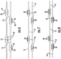
- FIGs. 6-8 address this problem by providing multiple smaller refrigerant pathways 32 in each tube 12 of the plurality of tubes 12.
- two, three, or four pathways 32 may be arranged in each tube 12 to decrease the pressure drop compared to a similar-sized tube 12 with a single pathway while increasing the heat transfer capability of the tube 12 and reducing connections to the header. While it is possible to include more than four pathways 32 in the tube 12, the heat transfer effectiveness of the additional pathways will be decreased since heat conduction from innermost pathways will be limited compared to the outermost pathways.
- louvers 22 may be utilized with these multi-pathway 32 configurations to increase heat transfer and to provide condensate drainage through the web openings 24.
- the heat exchanger 10 may include vortex generators, for example, tabs 34 disposed along the web 14.
- the tabs 34 are oriented across the airflow 20, as shown schematically in FIG. 11 , in order to generate streamwise votices 36 in the airflow 20 as the airflow passes along the web 14.
- the presence of vortices 36 can increase heat transfer between the web 14 and the airflow 20.
- the tabs 34 are triangular in shape, or may be other shapes, for example, trapezoidal, or asymmetrically polygonal, or the like, to generate the desired vortices 36.
- the tabs 34 are disposed in rows 40 extending along a tube length 38, with multiple rows, for example, two or three rows of tabs 34 between adjacent tubes 12.
- the positions of tabs 34 in a first row 40a may be staggered relative to the positions of tabs 34 in a second row 40b, or may be aligned, depending on the vortex 36 desired.
- tabs 34 are aligned such that a tab tip 42 of the tabs 34 faces the same direction, while according to the invention as shown in FIG. 12 , tab tips 42 of tabs 34 or rows of tabs 34 face opposing directions. Further, as shown in FIG. 13 , tabs 34 may be located and oriented to boost a strength of the vortices 36 along the web 14.
- the webs 14 may not be substantially planar, but may be a wave or ruffle shape to further have a desired effect on the airflow 20, such as increased vortex generation.
- the wavy web 14 may be utilized in conjunction with the louvers 22, and/or tabs 34.
Landscapes
- Engineering & Computer Science (AREA)
- Physics & Mathematics (AREA)
- Thermal Sciences (AREA)
- Mechanical Engineering (AREA)
- General Engineering & Computer Science (AREA)
- Geometry (AREA)
- Heat-Exchange Devices With Radiators And Conduit Assemblies (AREA)
Claims (9)
- Wärmetauscher (10), der Folgendes umfasst:eine Anzahl von Röhren (12), die im Wesentlichen quer zu einer Richtung eines Luftstroms durch den Wärmetauscher (10) auszurichten sind und in einer Mehrzahl von Reihen (40, 40a, 40b) von Röhren (12) anzuordnen sind, die sich im Wesentlichen entlang der Richtung des Luftstroms erstrecken;eine Mehrzahl von Stegen (14), die im Wesentlichen einstückig mit mindestens zwei Röhren (12) der Mehrzahl von Röhren (12) sind, wobei sich jeder Steg (14) zwischen benachbarten Röhren (12) der Mehrzahl von Röhren (12) erstreckt und damit verbunden ist; undeine Mehrzahl von Laschen (34), die an der Mehrzahl von Stegen (14) im Wesentlichen quer zu dem Luftstrom angeordnet sind, um Wirbel in dem Luftstrom zu erzeugen;wobei die Mehrzahl von Laschen (34) eine erste Reihe von Laschen (34) und eine zweite Reihe von Laschen (34) umfasst, wobei sich die erste Reihe von Laschen (34) entlang einer Röhrenlänge (38) zwischen einem Paar von benachbarten Röhren (12) der Mehrzahl von Röhren (12) erstreckt, und wobei sich die zweite Reihe von Laschen (34) parallel zu der ersten Reihe von Laschen (34) zwischen demselben Paar von benachbarten Röhren (12) der Mehrzahl von Röhren (12) erstreckt; dadurch gekennzeichnet, dass sich die Spitzen (42) der Laschen (34) der ersten Reihe in eine gemeinsame erste Richtung erstrecken, und dass sich die Spitzen (42) der Laschen (34) der zweiten Reihe in eine gemeinsame zweite Richtung erstrecken, die unterschiedlich zu der ersten Richtung ist.
- Wärmetauscher (10) nach Anspruch 1, wobei die Mehrzahl von Laschen (34) im Wesentlichen dreieckig oder trapezförmig ist.
- Wärmetauscher (10) nach Anspruch 1, wobei mindestens eine Röhre (12) der Mehrzahl von Röhren (12) einen Querschnitt mit einem Seitenverhältnis von mehr als 1:1 relativ zu einem im Wesentlichen horizontalen Steg (14) aufweist.
- Wärmetauscher (10) nach Anspruch 1, wobei die mindestens eine Röhre (12) der Mehrzahl von Röhren (12) einen ovalen oder schaufelprofilförmigen Querschnitt hat.
- Wärmetauscher (10) nach Anspruch 3, wobei die mindestens eine Röhre (12) der Mehrzahl von Röhren (12) zwei oder mehr fluidleitende Wege umfasst.
- Wärmetauscher (10) nach Anspruch 4, wobei die Anzahl von fluidleitenden Wegen der mindestens einen Röhre (12) in dem Bereich von zwei bis vier liegt.
- Wärmetauscher (10) nach Anspruch 1, der ferner eine oder mehrere Lamellen (22) umfasst, die in der Mehrzahl von Stegen (14) angeordnet sind.
- Wärmetauscher (10) nach Anspruch 6, der ferner zwei oder mehr Lamellen (22) umfasst, die in zwei oder mehr Lamellenreihen an einem Steg (14) zwischen benachbarten Röhren (12) der Mehrzahl von Röhren (12) angeordnet sind.
- Wärmetauscher (10) nach Anspruch 7 oder 8, wobei die eine oder die mehreren Lamellen (22) eine Lamellenfläche aufweisen, die im Wesentlichen parallel zu der Richtung des Luftstroms ausgerichtet sind.
Applications Claiming Priority (2)
| Application Number | Priority Date | Filing Date | Title |
|---|---|---|---|
| US201161475448P | 2011-04-14 | 2011-04-14 | |
| PCT/US2012/032984 WO2012142070A1 (en) | 2011-04-14 | 2012-04-11 | Heat exchanger |
Publications (2)
| Publication Number | Publication Date |
|---|---|
| EP2697589A1 EP2697589A1 (de) | 2014-02-19 |
| EP2697589B1 true EP2697589B1 (de) | 2020-09-30 |
Family
ID=46022655
Family Applications (1)
| Application Number | Title | Priority Date | Filing Date |
|---|---|---|---|
| EP12717951.3A Active EP2697589B1 (de) | 2011-04-14 | 2012-04-11 | Wärmetauscher |
Country Status (5)
| Country | Link |
|---|---|
| US (1) | US20140027098A1 (de) |
| EP (1) | EP2697589B1 (de) |
| CN (1) | CN103477177B (de) |
| ES (1) | ES2834434T3 (de) |
| WO (1) | WO2012142070A1 (de) |
Families Citing this family (23)
| Publication number | Priority date | Publication date | Assignee | Title |
|---|---|---|---|---|
| US20120261104A1 (en) * | 2011-04-12 | 2012-10-18 | Altex Technologies Corporation | Microchannel Heat Exchangers and Reactors |
| US20140231056A1 (en) * | 2011-10-13 | 2014-08-21 | Carrier Corporation | Heat exchanger |
| KR20150126386A (ko) * | 2013-03-01 | 2015-11-11 | 사파 에이에스 | 멀티 포트 압출 성형체 (mpe) 구성 |
| EP3194872B1 (de) * | 2014-09-05 | 2019-10-30 | Carrier Corporation | Extrudierter multiport-wärmetauscher |
| EP3314189B1 (de) | 2015-06-29 | 2021-01-27 | Carrier Corporation | Mikroröhrchenwärmetauscher |
| US10378835B2 (en) * | 2016-03-25 | 2019-08-13 | Unison Industries, Llc | Heat exchanger with non-orthogonal perforations |
| EP3491323B1 (de) * | 2016-08-08 | 2024-04-17 | Grandholm Production Services Ltd. | Wärmetauscher mit mikrokanal-struktur oder flügelrohr-struktur |
| CN107869930B (zh) * | 2016-09-28 | 2020-08-11 | 丹佛斯微通道换热器(嘉兴)有限公司 | 用于换热器的换热组件、换热器和模具 |
| AT518986B1 (de) * | 2016-10-07 | 2018-03-15 | Dipl Ing Thomas Euler Rolle | Wärmetauscher |
| FR3057943A1 (fr) * | 2016-10-20 | 2018-04-27 | Patrick Ouvry | Dispositif pour accumulateur thermique a prise en glace |
| ES2904856T3 (es) * | 2017-08-03 | 2022-04-06 | Mitsubishi Electric Corp | Intercambiador de calor y dispositivo de ciclo de refrigeración |
| CN107504854A (zh) * | 2017-09-29 | 2017-12-22 | 上海蓝滨石化设备有限责任公司 | 一种表面多孔高通量传热板管及板式再沸器 |
| CN107976101B (zh) * | 2017-12-22 | 2023-07-14 | 上海发电设备成套设计研究院有限责任公司 | 一种外翅片换热管的使用方法 |
| JP7044969B2 (ja) * | 2018-03-01 | 2022-03-31 | ダイキン工業株式会社 | 熱交換器 |
| CN108626915A (zh) * | 2018-06-22 | 2018-10-09 | 河南科隆集团有限公司 | 冰箱/冰柜上使用的平行流蒸发器 |
| JPWO2020012549A1 (ja) * | 2018-07-10 | 2021-04-30 | 三菱電機株式会社 | 熱交換装置、熱交換器ユニット及び冷凍サイクル装置 |
| US11255588B2 (en) | 2018-08-03 | 2022-02-22 | Hoshizaki America, Inc. | Ultrasonic bin control in an ice machine |
| WO2020044391A1 (ja) * | 2018-08-27 | 2020-03-05 | 三菱電機株式会社 | 熱交換器、熱交換器ユニット、及び冷凍サイクル装置 |
| KR102130086B1 (ko) * | 2018-11-29 | 2020-07-06 | 한국생산기술연구원 | 익형 열교환튜브를 포함하는 열교환기 |
| US11098962B2 (en) * | 2019-02-22 | 2021-08-24 | Forum Us, Inc. | Finless heat exchanger apparatus and methods |
| DE202019104073U1 (de) | 2019-07-23 | 2020-10-26 | Bundy Refrigeration Gmbh | Extrudierter Flügelrohrabschnitt, Flügelrohr mit extrudiertem Flügelrohrabschnitt und Wärmetauscher mit Flügelrohr |
| EP3982074B1 (de) * | 2019-10-08 | 2025-01-01 | Hangzhou Sanhua Research Institute Co., Ltd. | Wärmetauscher |
| DE102023108462A1 (de) * | 2023-04-03 | 2024-10-10 | Fraunhofer-Gesellschaft zur Förderung der angewandten Forschung eingetragener Verein | Bauteil und Verfahren zur Herstellung eines Bauteils zur Übertragung von Wärme |
Family Cites Families (17)
| Publication number | Priority date | Publication date | Assignee | Title |
|---|---|---|---|---|
| US3046758A (en) * | 1960-08-11 | 1962-07-31 | Olin Mathieson | Heat exchangers |
| FR1524182A (fr) * | 1967-02-24 | 1968-05-10 | Rubanox Soc | Perfectionnements aux échangeurs thermiques à ailettes |
| US4817709A (en) * | 1987-12-02 | 1989-04-04 | Carrier Corporation | Ramp wing enhanced plate fin |
| JPH0651758U (ja) * | 1990-03-13 | 1994-07-15 | 三星電子株式会社 | 冷蔵庫用蒸発器構造 |
| US5647433A (en) * | 1993-12-09 | 1997-07-15 | Sanden Corporation | Heat exchanger |
| JP4451981B2 (ja) * | 2000-11-21 | 2010-04-14 | 三菱重工業株式会社 | 熱交換チューブ及びフィンレス熱交換器 |
| GB0107107D0 (en) * | 2001-03-21 | 2001-05-09 | Dwyer Robert C | Fluid to gas exchangers |
| JP2004125352A (ja) * | 2002-10-07 | 2004-04-22 | Denso Corp | 熱交換器 |
| US7007504B2 (en) * | 2003-01-29 | 2006-03-07 | Kyeong-Hwa Kang | Condenser |
| US7028766B2 (en) * | 2003-11-25 | 2006-04-18 | Alcoa Inc. | Heat exchanger tubing with connecting member and fins and methods of heat exchange |
| JP4338667B2 (ja) * | 2005-04-01 | 2009-10-07 | カルソニックカンセイ株式会社 | 熱交換器 |
| JP2006322698A (ja) * | 2005-04-22 | 2006-11-30 | Denso Corp | 熱交換器 |
| CN1967135A (zh) * | 2006-04-21 | 2007-05-23 | 王磊 | 一种铝制挤压薄壁型材 |
| CN101294779A (zh) * | 2008-04-15 | 2008-10-29 | 西安交通大学 | 一种换热管翅结构 |
| CN101493229A (zh) * | 2009-01-15 | 2009-07-29 | 哈尔滨工业大学 | 一种多尾管脉动燃烧器控制方法及装置 |
| CN101493299A (zh) * | 2009-01-23 | 2009-07-29 | 江苏双良空调设备股份有限公司 | 机翼管换热器 |
| US20110036553A1 (en) * | 2009-08-12 | 2011-02-17 | Brian John Christen | Integral evaporator and defrost heater system |
-
2012
- 2012-04-11 US US14/111,077 patent/US20140027098A1/en not_active Abandoned
- 2012-04-11 EP EP12717951.3A patent/EP2697589B1/de active Active
- 2012-04-11 ES ES12717951T patent/ES2834434T3/es active Active
- 2012-04-11 CN CN201280018452.1A patent/CN103477177B/zh active Active
- 2012-04-11 WO PCT/US2012/032984 patent/WO2012142070A1/en not_active Ceased
Non-Patent Citations (1)
| Title |
|---|
| None * |
Also Published As
| Publication number | Publication date |
|---|---|
| US20140027098A1 (en) | 2014-01-30 |
| CN103477177A (zh) | 2013-12-25 |
| EP2697589A1 (de) | 2014-02-19 |
| WO2012142070A1 (en) | 2012-10-18 |
| ES2834434T3 (es) | 2021-06-17 |
| CN103477177B (zh) | 2016-11-16 |
Similar Documents
| Publication | Publication Date | Title |
|---|---|---|
| EP2697589B1 (de) | Wärmetauscher | |
| US7913750B2 (en) | Louvered air center with vortex generating extensions for compact heat exchanger | |
| US20100263847A1 (en) | Microchannel heat exchanger | |
| CN208254300U (zh) | 带有错位翅片的换热器盘管 | |
| JP6647319B2 (ja) | 熱交換器 | |
| US20140231056A1 (en) | Heat exchanger | |
| US20160123681A1 (en) | Fin tube heat exchanger | |
| CN102128555A (zh) | 换热器用鳍片及具有该鳍片的换热器 | |
| EP3608618B1 (de) | Wärmetauscher und kühlzyklusvorrichtung | |
| EP3314189B1 (de) | Mikroröhrchenwärmetauscher | |
| JP2005106328A (ja) | 熱交換装置 | |
| EP3362759B1 (de) | Wärmetauscher für hlk-geräte im wohnbereich | |
| CN108474629B (zh) | 用于热交换器应用的折叠导管 | |
| US20060266503A1 (en) | Heat transfer fin, heat exchanger, evaporator and condenser for use in car air-conditioner | |
| US12078431B2 (en) | Microchannel heat exchanger for a furnace | |
| JP2001304719A (ja) | モジュール形多重流路扁平管蒸発器 | |
| JP2009162433A (ja) | 伝熱部材 | |
| CN212457513U (zh) | 换热器、空调器 | |
| JP2009139085A (ja) | 熱交換器用ルーバ式波型インサート | |
| WO2016036732A1 (en) | Frost tolerant microchannel heat exchanger for heat pump and refrigeration applications | |
| US20250172343A1 (en) | Heat exchanger, air conditioning system and heat exchange system | |
| US20240060727A1 (en) | Fin device, heat exchanger having the same and method for manufacturing a fin device | |
| KR20110090522A (ko) | 열교환기용 핀 | |
| JP2008286446A (ja) | 伝熱部材およびそれを用いた熱交換器 |
Legal Events
| Date | Code | Title | Description |
|---|---|---|---|
| PUAI | Public reference made under article 153(3) epc to a published international application that has entered the european phase |
Free format text: ORIGINAL CODE: 0009012 |
|
| 17P | Request for examination filed |
Effective date: 20131015 |
|
| AK | Designated contracting states |
Kind code of ref document: A1 Designated state(s): AL AT BE BG CH CY CZ DE DK EE ES FI FR GB GR HR HU IE IS IT LI LT LU LV MC MK MT NL NO PL PT RO RS SE SI SK SM TR |
|
| RIN1 | Information on inventor provided before grant (corrected) |
Inventor name: YAZDANI, MIAD Inventor name: WHITON, JOHN H. Inventor name: MUNOZ, JULES R. Inventor name: ALAHYARI, ABBAS A. |
|
| DAX | Request for extension of the european patent (deleted) | ||
| STAA | Information on the status of an ep patent application or granted ep patent |
Free format text: STATUS: EXAMINATION IS IN PROGRESS |
|
| 17Q | First examination report despatched |
Effective date: 20190916 |
|
| GRAP | Despatch of communication of intention to grant a patent |
Free format text: ORIGINAL CODE: EPIDOSNIGR1 |
|
| STAA | Information on the status of an ep patent application or granted ep patent |
Free format text: STATUS: GRANT OF PATENT IS INTENDED |
|
| INTG | Intention to grant announced |
Effective date: 20200515 |
|
| GRAS | Grant fee paid |
Free format text: ORIGINAL CODE: EPIDOSNIGR3 |
|
| GRAA | (expected) grant |
Free format text: ORIGINAL CODE: 0009210 |
|
| STAA | Information on the status of an ep patent application or granted ep patent |
Free format text: STATUS: THE PATENT HAS BEEN GRANTED |
|
| AK | Designated contracting states |
Kind code of ref document: B1 Designated state(s): AL AT BE BG CH CY CZ DE DK EE ES FI FR GB GR HR HU IE IS IT LI LT LU LV MC MK MT NL NO PL PT RO RS SE SI SK SM TR |
|
| REG | Reference to a national code |
Ref country code: CH Ref legal event code: EP Ref country code: GB Ref legal event code: FG4D |
|
| REG | Reference to a national code |
Ref country code: AT Ref legal event code: REF Ref document number: 1319235 Country of ref document: AT Kind code of ref document: T Effective date: 20201015 |
|
| REG | Reference to a national code |
Ref country code: DE Ref legal event code: R096 Ref document number: 602012072554 Country of ref document: DE |
|
| REG | Reference to a national code |
Ref country code: IE Ref legal event code: FG4D |
|
| PG25 | Lapsed in a contracting state [announced via postgrant information from national office to epo] |
Ref country code: BG Free format text: LAPSE BECAUSE OF FAILURE TO SUBMIT A TRANSLATION OF THE DESCRIPTION OR TO PAY THE FEE WITHIN THE PRESCRIBED TIME-LIMIT Effective date: 20201230 Ref country code: SE Free format text: LAPSE BECAUSE OF FAILURE TO SUBMIT A TRANSLATION OF THE DESCRIPTION OR TO PAY THE FEE WITHIN THE PRESCRIBED TIME-LIMIT Effective date: 20200930 Ref country code: NO Free format text: LAPSE BECAUSE OF FAILURE TO SUBMIT A TRANSLATION OF THE DESCRIPTION OR TO PAY THE FEE WITHIN THE PRESCRIBED TIME-LIMIT Effective date: 20201230 Ref country code: HR Free format text: LAPSE BECAUSE OF FAILURE TO SUBMIT A TRANSLATION OF THE DESCRIPTION OR TO PAY THE FEE WITHIN THE PRESCRIBED TIME-LIMIT Effective date: 20200930 Ref country code: GR Free format text: LAPSE BECAUSE OF FAILURE TO SUBMIT A TRANSLATION OF THE DESCRIPTION OR TO PAY THE FEE WITHIN THE PRESCRIBED TIME-LIMIT Effective date: 20201231 Ref country code: FI Free format text: LAPSE BECAUSE OF FAILURE TO SUBMIT A TRANSLATION OF THE DESCRIPTION OR TO PAY THE FEE WITHIN THE PRESCRIBED TIME-LIMIT Effective date: 20200930 |
|
| REG | Reference to a national code |
Ref country code: AT Ref legal event code: MK05 Ref document number: 1319235 Country of ref document: AT Kind code of ref document: T Effective date: 20200930 |
|
| PG25 | Lapsed in a contracting state [announced via postgrant information from national office to epo] |
Ref country code: LV Free format text: LAPSE BECAUSE OF FAILURE TO SUBMIT A TRANSLATION OF THE DESCRIPTION OR TO PAY THE FEE WITHIN THE PRESCRIBED TIME-LIMIT Effective date: 20200930 Ref country code: RS Free format text: LAPSE BECAUSE OF FAILURE TO SUBMIT A TRANSLATION OF THE DESCRIPTION OR TO PAY THE FEE WITHIN THE PRESCRIBED TIME-LIMIT Effective date: 20200930 |
|
| REG | Reference to a national code |
Ref country code: NL Ref legal event code: MP Effective date: 20200930 |
|
| REG | Reference to a national code |
Ref country code: LT Ref legal event code: MG4D |
|
| PG25 | Lapsed in a contracting state [announced via postgrant information from national office to epo] |
Ref country code: EE Free format text: LAPSE BECAUSE OF FAILURE TO SUBMIT A TRANSLATION OF THE DESCRIPTION OR TO PAY THE FEE WITHIN THE PRESCRIBED TIME-LIMIT Effective date: 20200930 Ref country code: CZ Free format text: LAPSE BECAUSE OF FAILURE TO SUBMIT A TRANSLATION OF THE DESCRIPTION OR TO PAY THE FEE WITHIN THE PRESCRIBED TIME-LIMIT Effective date: 20200930 Ref country code: LT Free format text: LAPSE BECAUSE OF FAILURE TO SUBMIT A TRANSLATION OF THE DESCRIPTION OR TO PAY THE FEE WITHIN THE PRESCRIBED TIME-LIMIT Effective date: 20200930 Ref country code: NL Free format text: LAPSE BECAUSE OF FAILURE TO SUBMIT A TRANSLATION OF THE DESCRIPTION OR TO PAY THE FEE WITHIN THE PRESCRIBED TIME-LIMIT Effective date: 20200930 Ref country code: PT Free format text: LAPSE BECAUSE OF FAILURE TO SUBMIT A TRANSLATION OF THE DESCRIPTION OR TO PAY THE FEE WITHIN THE PRESCRIBED TIME-LIMIT Effective date: 20210201 Ref country code: RO Free format text: LAPSE BECAUSE OF FAILURE TO SUBMIT A TRANSLATION OF THE DESCRIPTION OR TO PAY THE FEE WITHIN THE PRESCRIBED TIME-LIMIT Effective date: 20200930 Ref country code: SM Free format text: LAPSE BECAUSE OF FAILURE TO SUBMIT A TRANSLATION OF THE DESCRIPTION OR TO PAY THE FEE WITHIN THE PRESCRIBED TIME-LIMIT Effective date: 20200930 |
|
| PG25 | Lapsed in a contracting state [announced via postgrant information from national office to epo] |
Ref country code: AT Free format text: LAPSE BECAUSE OF FAILURE TO SUBMIT A TRANSLATION OF THE DESCRIPTION OR TO PAY THE FEE WITHIN THE PRESCRIBED TIME-LIMIT Effective date: 20200930 Ref country code: AL Free format text: LAPSE BECAUSE OF FAILURE TO SUBMIT A TRANSLATION OF THE DESCRIPTION OR TO PAY THE FEE WITHIN THE PRESCRIBED TIME-LIMIT Effective date: 20200930 Ref country code: PL Free format text: LAPSE BECAUSE OF FAILURE TO SUBMIT A TRANSLATION OF THE DESCRIPTION OR TO PAY THE FEE WITHIN THE PRESCRIBED TIME-LIMIT Effective date: 20200930 Ref country code: IS Free format text: LAPSE BECAUSE OF FAILURE TO SUBMIT A TRANSLATION OF THE DESCRIPTION OR TO PAY THE FEE WITHIN THE PRESCRIBED TIME-LIMIT Effective date: 20210130 |
|
| REG | Reference to a national code |
Ref country code: ES Ref legal event code: FG2A Ref document number: 2834434 Country of ref document: ES Kind code of ref document: T3 Effective date: 20210617 |
|
| PG25 | Lapsed in a contracting state [announced via postgrant information from national office to epo] |
Ref country code: SK Free format text: LAPSE BECAUSE OF FAILURE TO SUBMIT A TRANSLATION OF THE DESCRIPTION OR TO PAY THE FEE WITHIN THE PRESCRIBED TIME-LIMIT Effective date: 20200930 |
|
| REG | Reference to a national code |
Ref country code: DE Ref legal event code: R097 Ref document number: 602012072554 Country of ref document: DE |
|
| PLBE | No opposition filed within time limit |
Free format text: ORIGINAL CODE: 0009261 |
|
| STAA | Information on the status of an ep patent application or granted ep patent |
Free format text: STATUS: NO OPPOSITION FILED WITHIN TIME LIMIT |
|
| PG25 | Lapsed in a contracting state [announced via postgrant information from national office to epo] |
Ref country code: DK Free format text: LAPSE BECAUSE OF FAILURE TO SUBMIT A TRANSLATION OF THE DESCRIPTION OR TO PAY THE FEE WITHIN THE PRESCRIBED TIME-LIMIT Effective date: 20200930 |
|
| 26N | No opposition filed |
Effective date: 20210701 |
|
| PG25 | Lapsed in a contracting state [announced via postgrant information from national office to epo] |
Ref country code: IT Free format text: LAPSE BECAUSE OF FAILURE TO SUBMIT A TRANSLATION OF THE DESCRIPTION OR TO PAY THE FEE WITHIN THE PRESCRIBED TIME-LIMIT Effective date: 20200930 |
|
| REG | Reference to a national code |
Ref country code: DE Ref legal event code: R119 Ref document number: 602012072554 Country of ref document: DE |
|
| PG25 | Lapsed in a contracting state [announced via postgrant information from national office to epo] |
Ref country code: SI Free format text: LAPSE BECAUSE OF FAILURE TO SUBMIT A TRANSLATION OF THE DESCRIPTION OR TO PAY THE FEE WITHIN THE PRESCRIBED TIME-LIMIT Effective date: 20200930 Ref country code: MC Free format text: LAPSE BECAUSE OF FAILURE TO SUBMIT A TRANSLATION OF THE DESCRIPTION OR TO PAY THE FEE WITHIN THE PRESCRIBED TIME-LIMIT Effective date: 20200930 |
|
| GBPC | Gb: european patent ceased through non-payment of renewal fee |
Effective date: 20210411 |
|
| PG25 | Lapsed in a contracting state [announced via postgrant information from national office to epo] |
Ref country code: LU Free format text: LAPSE BECAUSE OF NON-PAYMENT OF DUE FEES Effective date: 20210411 |
|
| REG | Reference to a national code |
Ref country code: BE Ref legal event code: MM Effective date: 20210430 |
|
| PG25 | Lapsed in a contracting state [announced via postgrant information from national office to epo] |
Ref country code: GB Free format text: LAPSE BECAUSE OF NON-PAYMENT OF DUE FEES Effective date: 20210411 Ref country code: DE Free format text: LAPSE BECAUSE OF NON-PAYMENT OF DUE FEES Effective date: 20211103 Ref country code: CH Free format text: LAPSE BECAUSE OF NON-PAYMENT OF DUE FEES Effective date: 20210430 Ref country code: LI Free format text: LAPSE BECAUSE OF NON-PAYMENT OF DUE FEES Effective date: 20210430 |
|
| PG25 | Lapsed in a contracting state [announced via postgrant information from national office to epo] |
Ref country code: IE Free format text: LAPSE BECAUSE OF NON-PAYMENT OF DUE FEES Effective date: 20210411 |
|
| PG25 | Lapsed in a contracting state [announced via postgrant information from national office to epo] |
Ref country code: IS Free format text: LAPSE BECAUSE OF FAILURE TO SUBMIT A TRANSLATION OF THE DESCRIPTION OR TO PAY THE FEE WITHIN THE PRESCRIBED TIME-LIMIT Effective date: 20210130 |
|
| PG25 | Lapsed in a contracting state [announced via postgrant information from national office to epo] |
Ref country code: BE Free format text: LAPSE BECAUSE OF NON-PAYMENT OF DUE FEES Effective date: 20210430 |
|
| PG25 | Lapsed in a contracting state [announced via postgrant information from national office to epo] |
Ref country code: HU Free format text: LAPSE BECAUSE OF FAILURE TO SUBMIT A TRANSLATION OF THE DESCRIPTION OR TO PAY THE FEE WITHIN THE PRESCRIBED TIME-LIMIT; INVALID AB INITIO Effective date: 20120411 Ref country code: CY Free format text: LAPSE BECAUSE OF FAILURE TO SUBMIT A TRANSLATION OF THE DESCRIPTION OR TO PAY THE FEE WITHIN THE PRESCRIBED TIME-LIMIT Effective date: 20200930 |
|
| PG25 | Lapsed in a contracting state [announced via postgrant information from national office to epo] |
Ref country code: MK Free format text: LAPSE BECAUSE OF FAILURE TO SUBMIT A TRANSLATION OF THE DESCRIPTION OR TO PAY THE FEE WITHIN THE PRESCRIBED TIME-LIMIT Effective date: 20200930 |
|
| PGFP | Annual fee paid to national office [announced via postgrant information from national office to epo] |
Ref country code: ES Payment date: 20240502 Year of fee payment: 13 |
|
| PG25 | Lapsed in a contracting state [announced via postgrant information from national office to epo] |
Ref country code: MT Free format text: LAPSE BECAUSE OF FAILURE TO SUBMIT A TRANSLATION OF THE DESCRIPTION OR TO PAY THE FEE WITHIN THE PRESCRIBED TIME-LIMIT Effective date: 20200930 |
|
| PGFP | Annual fee paid to national office [announced via postgrant information from national office to epo] |
Ref country code: FR Payment date: 20250319 Year of fee payment: 14 |
|
| PG25 | Lapsed in a contracting state [announced via postgrant information from national office to epo] |
Ref country code: TR Free format text: LAPSE BECAUSE OF FAILURE TO SUBMIT A TRANSLATION OF THE DESCRIPTION OR TO PAY THE FEE WITHIN THE PRESCRIBED TIME-LIMIT Effective date: 20200930 |