EP2697606B1 - Système géodésique pour marquer des points de mire - Google Patents
Système géodésique pour marquer des points de mire Download PDFInfo
- Publication number
- EP2697606B1 EP2697606B1 EP12714697.5A EP12714697A EP2697606B1 EP 2697606 B1 EP2697606 B1 EP 2697606B1 EP 12714697 A EP12714697 A EP 12714697A EP 2697606 B1 EP2697606 B1 EP 2697606B1
- Authority
- EP
- European Patent Office
- Prior art keywords
- marking
- unit
- air vehicle
- target point
- target
- Prior art date
- Legal status (The legal status is an assumption and is not a legal conclusion. Google has not performed a legal analysis and makes no representation as to the accuracy of the status listed.)
- Active
Links
Images


Classifications
-
- G—PHYSICS
- G01—MEASURING; TESTING
- G01C—MEASURING DISTANCES, LEVELS OR BEARINGS; SURVEYING; NAVIGATION; GYROSCOPIC INSTRUMENTS; PHOTOGRAMMETRY OR VIDEOGRAMMETRY
- G01C15/00—Surveying instruments or accessories not provided for in groups G01C1/00 - G01C13/00
-
- B—PERFORMING OPERATIONS; TRANSPORTING
- B64—AIRCRAFT; AVIATION; COSMONAUTICS
- B64C—AEROPLANES; HELICOPTERS
- B64C19/00—Aircraft control not otherwise provided for
-
- B—PERFORMING OPERATIONS; TRANSPORTING
- B64—AIRCRAFT; AVIATION; COSMONAUTICS
- B64C—AEROPLANES; HELICOPTERS
- B64C39/00—Aircraft not otherwise provided for
- B64C39/02—Aircraft not otherwise provided for characterised by special use
-
- G—PHYSICS
- G01—MEASURING; TESTING
- G01C—MEASURING DISTANCES, LEVELS OR BEARINGS; SURVEYING; NAVIGATION; GYROSCOPIC INSTRUMENTS; PHOTOGRAMMETRY OR VIDEOGRAMMETRY
- G01C15/00—Surveying instruments or accessories not provided for in groups G01C1/00 - G01C13/00
- G01C15/002—Active optical surveying means
-
- G—PHYSICS
- G01—MEASURING; TESTING
- G01S—RADIO DIRECTION-FINDING; RADIO NAVIGATION; DETERMINING DISTANCE OR VELOCITY BY USE OF RADIO WAVES; LOCATING OR PRESENCE-DETECTING BY USE OF THE REFLECTION OR RERADIATION OF RADIO WAVES; ANALOGOUS ARRANGEMENTS USING OTHER WAVES
- G01S17/00—Systems using the reflection or reradiation of electromagnetic waves other than radio waves, e.g. lidar systems
- G01S17/02—Systems using the reflection of electromagnetic waves other than radio waves
- G01S17/06—Systems determining position data of a target
- G01S17/42—Simultaneous measurement of distance and other co-ordinates
-
- G—PHYSICS
- G01—MEASURING; TESTING
- G01S—RADIO DIRECTION-FINDING; RADIO NAVIGATION; DETERMINING DISTANCE OR VELOCITY BY USE OF RADIO WAVES; LOCATING OR PRESENCE-DETECTING BY USE OF THE REFLECTION OR RERADIATION OF RADIO WAVES; ANALOGOUS ARRANGEMENTS USING OTHER WAVES
- G01S19/00—Satellite radio beacon positioning systems; Determining position, velocity or attitude using signals transmitted by such systems
- G01S19/01—Satellite radio beacon positioning systems transmitting time-stamped messages, e.g. GPS [Global Positioning System], GLONASS [Global Orbiting Navigation Satellite System] or GALILEO
- G01S19/03—Cooperating elements; Interaction or communication between different cooperating elements or between cooperating elements and receivers
- G01S19/07—Cooperating elements; Interaction or communication between different cooperating elements or between cooperating elements and receivers providing data for correcting measured positioning data, e.g. DGPS [differential GPS] or ionosphere corrections
- G01S19/071—DGPS corrections
-
- G—PHYSICS
- G01—MEASURING; TESTING
- G01S—RADIO DIRECTION-FINDING; RADIO NAVIGATION; DETERMINING DISTANCE OR VELOCITY BY USE OF RADIO WAVES; LOCATING OR PRESENCE-DETECTING BY USE OF THE REFLECTION OR RERADIATION OF RADIO WAVES; ANALOGOUS ARRANGEMENTS USING OTHER WAVES
- G01S19/00—Satellite radio beacon positioning systems; Determining position, velocity or attitude using signals transmitted by such systems
- G01S19/01—Satellite radio beacon positioning systems transmitting time-stamped messages, e.g. GPS [Global Positioning System], GLONASS [Global Orbiting Navigation Satellite System] or GALILEO
- G01S19/03—Cooperating elements; Interaction or communication between different cooperating elements or between cooperating elements and receivers
- G01S19/10—Cooperating elements; Interaction or communication between different cooperating elements or between cooperating elements and receivers providing dedicated supplementary positioning signals
- G01S19/11—Cooperating elements; Interaction or communication between different cooperating elements or between cooperating elements and receivers providing dedicated supplementary positioning signals wherein the cooperating elements are pseudolites or satellite radio beacon positioning system signal repeaters
-
- G—PHYSICS
- G01—MEASURING; TESTING
- G01S—RADIO DIRECTION-FINDING; RADIO NAVIGATION; DETERMINING DISTANCE OR VELOCITY BY USE OF RADIO WAVES; LOCATING OR PRESENCE-DETECTING BY USE OF THE REFLECTION OR RERADIATION OF RADIO WAVES; ANALOGOUS ARRANGEMENTS USING OTHER WAVES
- G01S19/00—Satellite radio beacon positioning systems; Determining position, velocity or attitude using signals transmitted by such systems
- G01S19/38—Determining a navigation solution using signals transmitted by a satellite radio beacon positioning system
- G01S19/39—Determining a navigation solution using signals transmitted by a satellite radio beacon positioning system the satellite radio beacon positioning system transmitting time-stamped messages, e.g. GPS [Global Positioning System], GLONASS [Global Orbiting Navigation Satellite System] or GALILEO
- G01S19/42—Determining position
- G01S19/51—Relative positioning
-
- G—PHYSICS
- G05—CONTROLLING; REGULATING
- G05D—SYSTEMS FOR CONTROLLING OR REGULATING NON-ELECTRIC VARIABLES
- G05D1/00—Control of position, course, altitude or attitude of land, water, air or space vehicles, e.g. using automatic pilots
- G05D1/10—Simultaneous control of position or course in three dimensions
- G05D1/101—Simultaneous control of position or course in three dimensions specially adapted for aircraft
- G05D1/102—Simultaneous control of position or course in three dimensions specially adapted for aircraft specially adapted for vertical take-off of aircraft
-
- B—PERFORMING OPERATIONS; TRANSPORTING
- B64—AIRCRAFT; AVIATION; COSMONAUTICS
- B64U—UNMANNED AERIAL VEHICLES [UAV]; EQUIPMENT THEREFOR
- B64U2101/00—UAVs specially adapted for particular uses or applications
- B64U2101/30—UAVs specially adapted for particular uses or applications for imaging, photography or videography
-
- B—PERFORMING OPERATIONS; TRANSPORTING
- B64—AIRCRAFT; AVIATION; COSMONAUTICS
- B64U—UNMANNED AERIAL VEHICLES [UAV]; EQUIPMENT THEREFOR
- B64U2201/00—UAVs characterised by their flight controls
- B64U2201/20—Remote controls
Definitions
- the invention relates to a geodetic marker with a positioning device, in particular a theodolite, a total station or a GNSS system, in particular with a GNSS reference station, and with an auto-mobile aircraft for marking a known destination according to claim 1, a method for controlling a Marking with a marking system according to the invention according to claim 6, an auto-mobile aircraft according to claim 10 for a marking system according to the invention and a marking arrangement according to claim 13 for a marking system according to the invention.
- geodetic surveying equipment include the theodolite, tachymeter and total station, also referred to as an electronic tachymeter or computer tachymeter.
- a geodetic measuring device of the prior art is disclosed in the publication EP 1 686 350 described. Such devices have electrosensitive angular and distance measuring functions which allow direction and distance determination to a selected target. The angle or distance variables are determined in the inner reference system of the device and must be for a absolute position determination may still be linked to an external reference system.
- Many geodetic applications measure points by placing specially designed targets. These usually consist of a pole with a targetable module, e.g. a reflector for defining the measuring section or the measuring point. These target objects are targeted by means of a surveying device, determining a direction and a distance to the objects and thus deriving a position of the objects.
- a targetable module e.g. a reflector for defining the measuring section or the measuring point.
- a marking of already known target points or of points whose position was defined in advance of a marking process can take place.
- the position or the coordinates of the points to be marked are known in this case and should be marked.
- a pole or a surveying rod is usually also used, which is guided by a user and positioned on a target point.
- the user can approach the target position of the target point on the basis of position information generated by the surveying device, whereby the surveying rod is automatically aimed at by the surveying device by a second person or by an automatism assigned to the surveying device.
- the user can mark the point.
- Modern surveying equipment such as a total station for such marking and surveying tasks have microprocessors for digital processing and storage of acquired measurement data.
- the devices are in the Usually produced in a compact and integrated design, with mostly coaxial distance and angle measuring elements and computing, control and storage units are integrated in one device.
- means are integrated for the motorisation of the target optics, for reflectorless distance measurement, for the automatic target search and tracking and for the remote control of the entire device.
- Total stations known from the prior art furthermore have a radio data interface for establishing a radio connection to external peripheral components, such as e.g. to a data acquisition device, which can be configured in particular as a handheld data logger, remote control unit, field computer, notebook, small computer or PDA.
- a data acquisition device which can be configured in particular as a handheld data logger, remote control unit, field computer, notebook, small computer or PDA.
- the data interface it is possible to output measured data stored and stored by the total station for external further processing, to read in externally acquired measurement data for storage and / or further processing in the total station, remote control signals for remote control of the total station or another external component, in particular in mobile field use . and output control software in the total station.
- a sighting telescope such as an optical telescope
- the scope is generally rotatable about a vertical standing axis and about a horizontal tilting axis relative to a base of the measuring device so that the telescope can be aligned by pivoting and tilting on the point to be measured.
- Modern devices can additively to the optical view channel one in the Riflescope integrated and, for example coaxially or parallel aligned camera for capturing an image, wherein the captured image in particular as a live image on the display of the display control unit and / or on a display of the peripheral device used for remote control - such as the data logger or the remote control unit - can be displayed.
- the optics of the sighting device may have a manual focus - for example, an adjusting screw for changing the position of a focusing optics - or have an autofocus, wherein the changing of the focus position, for example by servomotors.
- Automatic focusing devices for riflescopes of geodetic devices are eg from DE 197 107 22 , of the DE 199 267 06 or the DE 199 495 80 known.
- the target unit or a surveying rod provided with the target unit is aimed at or observed by a stationary position-determining unit such as, for example, a dead-center station.
- a stationary position-determining unit such as, for example, a dead-center station.
- an operator can be directed by marking on the display of the target unit to the target point by means of correlation between the currently measured from the stationary measuring station position data, including camera image for the mobile station, stored data with the intended position of the target point , eg by indication of direction by means of an arrow on the display.
- a device for further acceleration and simplification of a surveying or stakeout method is disclosed in the European patent application EP 2 431 708 A1 described.
- a remote control unit is described with a camera for recording a camera image in a defined recording direction, wherein by means of a position determination unit and the camera, the image data of the camera are brought in a coordinate system in spatial relation with the target points.
- This allows the operator to target the target more selectively, further reducing the duration of the survey process.
- this target search by the operator continues to require an active search of the target point position and an associated, in particular multiple, comparison of the Target point position with its current position or the position of the survey staff.
- WO 2008/124713 A2 discloses a geodetic marker system with a remotely controllable destination unit.
- the object of the present invention is to provide a surveying or marking system with associated units for the system as well as a corresponding method with which a marking of a target point is faster, easier and with a higher degree of automation, especially in a terrain that is difficult to access with a surveying bar. can be done.
- a specific object of the invention is to provide a way to prevent a visual comparison of its position or a position of a surveying bar with a target point position to be carried out by a user during a marking process.
- the invention relates to a geodetic marking system for marking a known target point with an auto-mobile, unmanned, remotely controlled target unit, wherein the target unit according to the invention is embodied by an aircraft, and with a geodetic position determining arrangement for the external Istpositionsbehlen the target unit, wherein the target unit is designed in that the target unit is, at least temporarily, largely positionally fixed, in particular floating, positionable. Furthermore, the target unit carries a, in particular modular removable, marking unit for marking the target point.
- the marking system has a control unit, wherein the control unit is configured such that depending on, in particular continuously determinable, external actual position and a known target point position of the target point, the target unit in a defined target position, in particular in a defined tolerance range around the target position, relative to Target point position, in particular continuously, automatically controlled positionable and that, taking into account the actual position, the target position and a defined marking direction of the marking unit to the target point, the marking unit to mark the target point is controllable, so that the target point in the defined marking direction with geodetic accuracy, ie to millimeters accurate or with a sub-centimeter accuracy, especially sub-millimeter accuracy, markable.
- Such a marking system can enable marking of target points in such a way that the positioning of the marking target unit runs completely automatically and thus no iterative approach of a user to a predetermined target point is required.
- the aircraft can be remotely controlled, for example by means of radio signals or signals that are wired, via infrared or via Bluetooth to the destination unit to be controlled to a defined position.
- a target unit for example, as an off-road vehicle, however, we used in the invention, an airworthy aircraft which can be positioned by a targeted control of motor-driven rotors, wherein the respective aircraft unmanned and simultaneously, in particular remotely controlled, by means of the intended motorization is movable.
- a position of the target unit can be determined with the marking system.
- a position determination arrangement is provided. This arrangement may be a total station, a theodolite, a tachymeter or e.g. have a GNSS system, wherein each one corresponding to the corresponding arrangement module is arranged target unit side.
- a position comparison can be carried out on the basis of the currently determined target unit position and / or the target unit or the aircraft can be controlled depending on the respective positions. From this information, further, a target position for the target unit can be derived and this target position can be defined as a target position for the target unit. The control of the target unit can then take place such that it is controlled to the target position and positioned there. A positioning of the target unit can thus at least temporarily take place as far as possible fixed in position, ie the target unit can hold independent of external influences over a temporary period of time, a stationary position without fluctuation. This can be special be achieved by a coordinated control of the target unit.
- a determination of the position of the target unit or a deviation from a predetermined position can be carried out continuously by the position-determining arrangement in contact with the target unit.
- a transmission unit assigned to the position determination arrangement can provide positioning signals that can be received by a receiver at the destination unit. If this arrangement has e.g. a GNSS transmitter or a GNSS system is used to accurately determine the position of the target unit, the target unit may have a GNSS receiver, by means of which a position information can be received and from which a position can be determined.
- a GNSS system that is customary for this purpose can be represented, for example, by GPS or GLONASS.
- a GNSS antenna can be arranged at the destination unit in order to be able to receive the signals assigned to the respective system.
- a GNSS reference station may be provided, which is also designed to receive GNSS signals and also provides reference data or correction data, for example for one of the known DGPS, RTK or VRS methods for increasing accuracy for position determination.
- a target unit adapted for such a reference system can thus also be designed to receive correction signals and perform a geodetic position determination taking these signals into account.
- the actual position of the target unit can be determined by a module arranged on the target unit, for example a reflector of one Surveying equipment, for example, from a total station or a theodolite, is targeted.
- the position of the surveying device can already be known, for example, by virtue of the fact that a calibration process was carried out on the surveying device and the device could thus carry out its own position determination by measuring known points. If a reflector at the target unit is now targeted by this surveying station, the direction to the target unit can be determined by determining the orientation of an emitted measuring beam and a distance to the target unit can be determined by means of a distance measurement carried out by means of the measuring beam.
- the relative position of the target unit to the surveying device can be determined unambiguously and accurately, and with knowledge of the position of the surveying device an absolute, in particular geodetically accurate, positioning of the target unit can be derived.
- the control of the unit can be performed.
- control data can be obtained from the position information, and by means of this, the target unit can be driven or flown to a defined desired position.
- the desired position can be determined in particular from the coordinates or position information of a destination point. If this represents, for example, a ground point in the terrain, the ground point itself can be defined as the target point, which - as regards an alternative, non-inventive aspect - can be approached by a vehicle.
- a target area around the target position can be defined here, with the target point as reached as soon as the vehicle or the position of the vehicle indicating component is in the target area.
- a target position can be defined, for example, between two and ten meters vertically above the ground point or at a certain angle, in particular within a defined Angular range, and distance to the ground point is located.
- a target or target area which has a defined position tolerance, are clamped around the target position, wherein the target position is considered reached when the aircraft or in turn the component of the aircraft, which indicates its current position, in the Target range is located.
- the aircraft can maintain a variable within a predefined setpoint range by compensating counter-control against an externally acting deflection force.
- a described positioning of the target unit with geodetic accuracy can be used for different applications.
- the target unit is equipped with a marking unit or carries such a marking unit.
- the marking unit can be embodied as an optical marking unit, in particular as a laser beam source, the target point being optically visibly marked by emitting the laser beam, and / or a marking of the target point can be made by attaching a panel made of color, e.g. Spray paint or ink jet, make existing mark.
- the marking of the target point may be accomplished by subjecting an article, e.g. a magnet is "dropped" at the target point position by the target unit and thus placed on the target point.
- an adhesive marking for example a label or a reflector foil, may be applied to the target point or a projectile, e.g. a nail from the target unit are fired so that is marked by an impact of the projectile at the target point this.
- a control of the target unit and the marker for marking can be done by means of a control unit.
- This control unit can on the one hand control the positioning of the destination unit by means of a, in particular constantly running, comparison of the current position of the target unit (actual position), the target position and the target point position.
- the target unit can be moved to the desired position or desired range by the control unit, for example by generating control data, as a function of these positions and the target unit can be positioned or held there when the desired range is reached.
- the relative Be known ratio of actual, target and target point position and continue to be controlled by means of the control unit with additional consideration of a marking of the marking this unit so that the marking of the target point is done.
- the marking unit is activated and / or controlled so that the target point is marked when, taking into account the actual position of the target unit and the marking of the marking unit, the target point is exactly met or hit with a mark generated by the marking unit.
- the data processing that takes place for this purpose can be carried out, for example, on the target unit, on the surveying device or on a remote control unit.
- the position determination arrangement can have at least one transmission unit for transmitting positioning signals and the target unit can be configured such that the positioning signals, in particular by means of a GNSS antenna, can be received and the actual position of the destination unit can be determined from the positioning signals.
- a geodetically accurate position determination of the target unit can be made, which can be detected and taken into account for the positioning of the target unit.
- This type of position determination also assumes that the positioning signals provided by the transmitting unit can be received by the destination unit, ie that the signals are not blocked or blocked by any obstacles existing between the transmitting unit and the destination unit.
- the transmitting unit can be embodied as a GNSS transmitter, in particular a GNSS satellite, in particular a GPS, GLONASS or Galileo satellite, and the positioning signals can be embodied by GNSS signals or the transmitting unit can have a pseudo-satellite module and the positioning signal be embodied by pseudo-satellite signals. If, for example, the position of the aircraft and the marking of a target point in a closed space, for example in a production hall, take place, then often no GNSS signal can be received there from the destination unit. In this case, a positioning by means of a pseudo-satellite module, so-called pseudolites or pseudo-satellites, be made in the hall.
- the pseudolites can be placed at respectively known positions and can transmit position information therefrom by means of the pseudo-satellite signals, for example in a signal format similar to a GNSS signal, by means of which a position determination on the part of the target unit can again be carried out.
- the signals may allow a determination of a relative position within, for example, a coordinate system or an object coordinate system representing the manufacturing space.
- an absolute, global position determination of the target unit can also be indirectly feasible.
- signals from four pseudolites can be received by the aircraft, in particular, with a common time base of the signals, the reception of three signals makes a position determination exactly feasible. For example, when positioning the target unit in a known height, two signals for position determination may be sufficient.
- the position-determining arrangement may have a GNSS reference station for transmitting GNSS correction signals and the target unit may be designed such that the GNSS correction signals can be received and the actual position of the destination unit from the received GNSS signals and the GNSS Correction signals are determinable.
- the thus additionally provided correction signals enable a more exact absolute position determination of the target unit.
- the aircraft can have a reflector and the position-determining arrangement a geodetic surveying device, in particular the theodolite or total station.
- the surveying device has at least one targeting device, in particular a target telescope, wherein the targeting device is pivotable relative to a base of the surveying device for changing its orientation, in particular motorized, and at least one emission unit defining an optical target axis and a radiation source for emitting an optical measuring beam for distance measurement parallel, in particular coaxial, to the optical target axis has.
- an angle measurement functionality for high-precision detection of the alignment of the target axis and evaluation means for data storage and control of the alignment of the target device are provided.
- the measuring beam can thus be aligned with the reflector so that the actual position of the target unit can be determined.
- the Measuring radiation to the measuring unit reflected back and recorded there.
- a distance from the surveying device to the target unit or to the reflector can be determined from this reflected measuring radiation and the position of the target unit can be specified taking into account the alignment of the targeting device.
- a signal which can be transmitted to the destination unit in particular wherein the signal is embodied by a radio signal, a signal modulated by a laser beam or an electronic signal, can be position information, the position information being convertible into control data in a first processing unit assigned to the destination unit, or the control data itself, wherein the control data can be determined from the position information by means of a second processing unit assigned to the surveying device.
- the detected position information can be directly transmitted e.g. be transmitted by radio to the destination unit and destination unit side, the position information for control, in particular for the generation of control data, are used.
- the position information can be further processed directly on the side of the surveying device and based on this information control signals or control data for controlling the target unit to be transmitted to this.
- the target unit embodied as an aircraft can also be positioned, at least temporarily, largely horizontally so that it can be positioned in a fixed position, in particular an effect on the positioning by external influences, in particular air flow, pressure and / or temperature fluctuation, can be compensated in the vertical direction.
- a position compensation can ensure a correct and usable positioning of the destination unit. If, for example, a wind force or a wind direction changes, which is taken into account for a floating positioning of the aircraft, a counter-control with a drive unit, for example a rotor of the aircraft, can take place in response thereto. It may be advantageous if the aircraft largely holds its horizontal position in a backlash and compensation takes place a correction or repositioning mainly in the vertical direction.
- the marking system can have a remote control unit for controlling the destination unit, in particular wherein the remote control unit has a display for displaying information.
- control-relevant data can be transmitted and / or received to the destination unit, or else a manual control of the destination unit by an operator can take place.
- a communication and power supply between the remote control unit, the target unit and / or a surveying device can be done for example via a cable.
- data processing may be performed for control on the remote control unit, the remote control unit e.g. as a PDA, smartphone or tablet PC can be realized.
- a marking of positions of boreholes on a wall can be carried out with the marking system.
- a digital model of a building or room can be used in the system be deposited, depending on the model, a definition of the positions of the holes can be made.
- the target unit can also be positioned relative to a borehole position, for example likewise depending on the digital model, and thereby effect the marking of the hole, for example by visible laser radiation.
- an operator of the system can now set the respective borehole or mark the position manually and subsequently control the target unit to the next borehole position or automatically assume the next position. There again, such a mark can be made and thus the holes are sequentially marked or drilled.
- the target unit may have a sensor unit for determining an orientation and / or the actual position of the target unit, in particular an inclination sensor, a magnetometer, an acceleration sensor, a rotation rate sensor and / or a speed sensor.
- the target unit may have a component indicating the orientation of the target unit
- the marking system may have a detection device, in particular a camera, for detecting and / or targeting the component and for determining the orientation of the target unit from the position and arrangement of the component.
- the determination of position and orientation of the aircraft can be done for example by a laser tracker.
- the orientation of the aircraft may be detected by a measurement of the location of markers disposed on the unit by the scanning unit. From the knowledge of the location and the arrangement of the markers and the knowledge of the position of the laser tracker relative to the aircraft, the Orientation of the aircraft are derived. From the position and the orientation information follows the knowledge of the situation in space. Such a general method for orientation determination is described for example in US Pat WO 2006/097408 described.
- the orientation may also be determined by means of an offset of a receiver to a measuring beam axis which is defined by a measuring beam aimed at the receiver, the optical system of the receiver thereby having only a limited opening angle.
- the determination of the alignment can be carried out by a method, wherein a emitting of a laser beam in the direction of a detector arranged on the target unit takes place and an emission direction of the laser beam is defined. This is followed by determining an impact point of the laser beam on the detector. From this impact point, the direction of incidence is derived. Based on a linking of the direction of incidence with the direction of emission, it is now possible to determine the orientation of the detector relative to the laser source and thus the target unit.
- a method is for example from the WO 2008/138507 known.
- the position of the destination unit is tracked and a direction of movement is determined from the position changes. Based on the assumption that the direction of movement corresponds to a specific orientation of the destination unit, information about the orientation of the destination unit can be derived therefrom.
- the position change can be determined, for example, by means of a continuous position determination by GPS.
- the position and rotational position or orientation of an object in space can be effected by means of an optical measuring device.
- the measuring device can have an imaging optics and a detector which is spatially resolving in two dimensions.
- the object or the destination unit can have a known code pattern, eg a barcode or pseudo-random code, and the pattern detected with the measuring device can be evaluated. Depending on the location of the detected code can be closed by the respective location of the target unit in the room.
- a method corresponding to this principle is used, for example, in US Pat EP 1 066 497 revealed.
- the marking system according to the invention may also have a control functionality, wherein the actual position of the aircraft is continuously determined during execution of the control functionality controlled by the control unit during a Markierzeitmits.
- This actual position can be determined by means of an interaction of the geodetic surveying device with the reflector and / or by means of the sensor unit and the aircraft based on it are kept stable so that the target point is continuously marked throughout the Markierzeittens by means of the marking unit with geodetic accuracy.
- the positioning of the aircraft can be regulated such that the aircraft during the entire Markierzeitraps present in the desired position and / or the marking direction is continuously adjusted and / or in an at least temporarily non-complies the marking of the target point, an error is output.
- a method for controlling a geodetic-precision marking of a known destination point has an auto-mobile, unmanned, remotely controllable aircraft as destination unit, wherein an external actual position of the destination unit, in particular continuously, is determined.
- the target unit carries a, in particular modular detachable, marking unit for marking the target point.
- the target unit is positioned in a defined target position, in particular in a defined tolerance range around the target position, relative to the target point position, in particular continuously, depending on, in particular continuously determined, external actual position and a known target point position of the target point.
- the marking unit for marking the destination point is controlled so that the destination point is marked in the defined marking direction with geodetic accuracy.
- an aircraft target unit
- Such positioning may provide a general basis for further action to be performed on the destination unit.
- the marking of the target point can take place with the present invention.
- the target unit is initially controlled as a function of its actual position and the target point position in a specific position - in the target position - and positioned there largely fixed position.
- the marking unit is controlled in dependence on the actual position, the target position, in particular depending on whether the target unit is in the desired position or in the desired range, and the marking of the marking such that the target point is marked by the marking.
- positioning signals can be received by the target unit and the external actual position, in particular an alignment of the target unit, can be determined from the positioning signals, in particular wherein the positioning signals are embodied by GNSS signals, pseudo-satellite signals and / or GNSS correction signals and the actual position is determined from the GNSS signals and / or the GNSS-like signals, in particular taking into account the GNSS correction signals.
- a measuring beam can be reflected on the aircraft side and the outer actual position can be determined by means of the reflected measuring beam.
- an absolute, geodetically accurate position of the target unit can be determined and, based on this, a positioning thereof can be carried out. If it is necessary to ensure that the signals can be received when positioning signals or GNSS signals are used, a position determination can be carried out in the case of reflection of a measuring beam independently of possible signal shielding.
- an orientation of the target unit in particular in pitch, roll and yaw direction, and / or a distance to an object, in particular to an obstacle, determined, and / or an image, in particular wherein the image has the target point , are recorded.
- the target point can thus be located in the field of view of the camera.
- a determination of the orientation of the target unit can, for example, be taken into account in a control for positioning or be used for a required or for a positioning in a defined orientation.
- obstacles in a flight path or a route of the destination unit can be detected and either, in particular automatically, bypassed or the destination unit can be positioned taking into account the respective obstacle.
- images of an environment in which the target unit is moved can be detected.
- a movement or a path along which the destination unit moves can also be determined and, as a result, a continuous determination of the actual position can be derived.
- the target unit in the case of co-detection of the target point on an image, the target unit can furthermore be controlled or placed at a target position on the basis of the image information.
- a user can thus have image information available on the basis of which the target unit can also be controlled manually.
- the marking of the target point can take place with optically visible radiation and a radiation direction of the radiation can lie parallel, in particular coaxially, to the marking direction.
- the Marking radiation can be activated upon reaching the desired position and proper alignment of the marking and emitted continuously and / or pulsating to indicate the target point.
- the marking direction of the marking unit can be aligned in parallel, in particular automatically, with respect to the perpendicular direction and / or relative to the alignment of the target unit, in particular with the marking unit being gimbaled and / or the target unit having alignment means for the defined alignment of the marking direction, in particular wherein the marking unit is pivoted in two, in particular in three, axes. Due to the gimbal suspension, the marking direction can be automatically aligned parallel to the perpendicular direction, ie parallel to the gravity vector, the earth and has the consequence that an exact alignment of the target unit in a vertical positioning over the target point for marking the target point is not mandatory.
- the marking direction may be aligned by the alignment means such that the target point is marked at a certain angle to the plumb line.
- the alignment means can enable pivoting or rotation of the marking direction by up to three axes and thus not only punctiform marking of the target point, but also a marking by a pattern, which, for example, arises during rapid movement of a designed as laser radiation marker.
- a path in the context of the method, can be defined by waypoints, wherein the destination unit is moved along the path, in particular wherein an optimization of a path course, in particular automatically, takes place and / or the path has the destination point and / or the desired position, and / or marking the position of the waypoints as intermediate destination points continuously along the path.
- waypoints can be staked out, which define the way to a destination point and / or which intermediate destination points form and thus should also be marked.
- the movement path of the destination unit can be optimized, in particular if known obstacles are bypassed in advance by the definition of the waypoints.
- the marking of the waypoints can also by means of an optical system, such as a visible laser beam, or by means of a color marking, for example with a paint or spray paint done.
- the marking can run fully automatically, ie, the target unit moves continuously from waypoint to waypoint and makes, if necessary, each mark before or semiautomatic, ie the target unit automatically moves to a waypoint and holds the position to a user a signal for positioning on next waypoint there.
- information and / or control commands in particular the destination point position, can be entered into the destination unit, and / or information, in particular the captured image, in particular on a display, can be output.
- the actual position of the aircraft can be continuously determined during a regulation during a marking time window and the aircraft can be kept stable based on the measuring beam reflected by the aircraft device or by means of a sensor unit for determining an orientation and / or the actual position of the aircraft the target point is continuously marked during the entire marking time window by means of the marking unit with geodetic accuracy.
- the positioning of the aircraft can be regulated such that the aircraft is present in the desired position during the entire Markierzeitfen ⁇ and / or the marking direction are continuously adjusted and / or carried out at an at least temporarily non-complies the marking of the target point an error output.
- Another object of the invention is an auto-mobile, unmanned, remote-controlled target unit, wherein the target unit according to the invention is designed as an aircraft, in particular as a drone, for use in a marking system according to the invention.
- the target unit is also designed in such a way that the target unit is at least temporarily largely fixed in position, in particular floating, positionable. Furthermore, position information for determining an external actual position of the destination unit and for generating control data and / or the control data can be transmitted directly to the destination unit.
- the destination unit carries a marking unit for marking one destination point, in particular wherein the marking unit is modularly detachable, and the control data are configured such that, depending on the, in particular continuously determinable, external actual position and a known destination point position of the destination point, the destination unit in a defined target position , in particular in a defined tolerance range around the target position, relative to the target point position, in particular continuously, can be positioned.
- the marking unit can be controlled to mark the target point, so that the target point can be marked in the defined marking direction with geodetic precision.
- the target unit according to the invention can be embodied, for example, by an aircraft which can be positioned largely in a positionally stable manner by means of at least two rotors and / or nozzles.
- the Destination unit for example, by an all-terrain vehicle, which can be controlled to drive to a target position and is positioned so be embodied.
- the destination unit may be e.g. be remotely controlled by means of radio signals, via a laser beam or by cable, the target unit itself being unmanned and automobile, i. has a motorized drive, which provides an independent locomotion of the target unit is executed.
- the destination unit additionally has a marking unit with which a marking of the destination point can be carried out.
- the target unit can be controlled and placed taking into consideration the own position (actual position), the target point position and a position in which the target unit is to be positioned (target position). With an additional consideration of the marking direction in the control data, the destination point can then be geodetically accurately marked by the marking unit.
- a destination unit can have a receiver for positioning signals, in particular a GNSS antenna, and a processing unit for determining an actual position of the destination unit from the positioning signals.
- the positioning signals may be embodied by GNSS signals, in particular where the GNSS signals are represented by GPS, GLONASS or Galileo signals, pseudo-satellite signals and / or GNSS correction signals and the actual position from the GNSS signals and / or the GNSS-like signals, in particular taking into account the GNSS correction signals, be determinable.
- the target unit may have a reflector. By means of such receivers or by means of Reflectors, an absolute position of the target unit can be determined by either the positioning signals or GNSS signals detected and converted into position information or the reflector is targeted and thereby the position of the target unit is determined.
- a target unit according to the invention may further comprise a sensor unit for determining an orientation and / or the actual position of the target unit, in particular a tilt sensor, a magnetometer, an acceleration sensor, a rotation rate sensor and / or a speed sensor.
- a sensor unit for determining an orientation and / or the actual position of the target unit, in particular a tilt sensor, a magnetometer, an acceleration sensor, a rotation rate sensor and / or a speed sensor.
- the target unit according to the invention can have a sensor for measuring the distance to objects, in particular radar, whereby, for example, obstacles can be detected by means of this sensor and thus taken into account or avoided during the movement of the target unit.
- the target unit may further comprise an optical detection unit, in particular a camera, for detecting an image, in particular wherein the image has the target point or the target point is located in the image field.
- this detection unit such as a video camera
- one or more images of a camera environment or an aerial photograph of a terrain can be detected and detected by image processing processes such as a change in the position of the target unit.
- the image information can be used to perform the control of the target unit, in particular towards a defined position, and / or an operator provide image information for measurement or marking processes or images for documentation of a surveying process.
- a position determination of the destination unit can take place as a function of captured images.
- a series of images can be captured whose image areas each partially overlap.
- the overlapping areas can, for example, be matched by a comparison of patterns captured on the images, in particular by image processing or comparison of the overlapping areas of the images.
- the relative position of an image to a subsequent image can be determined and a movement progress of the image acquisition unit from the size of the Studentslappuhgs Kunststoffs and a rotation angle by which the subsequent image image processing must be rotated so that a match of a prominent pattern can be achieved in the overlap area and hence the destination unit.
- a recognition of distinctive waypoints, whose coordinates are known, take place and from this an absolute horizontal position can be determined directly.
- such a position determination for example, in case of failure of the GNSS system or coverage of the GNSS signals, so that no position determination is possible, be feasible, with a coordinatively known starting point of the target unit can be taken into account in the determination.
- zoom factors of one or more images can be compared with each other and, in turn, be deduced from any pattern matching a height change.
- the target unit can be identified on the basis of a time-invariant texture, e.g. Positionally stabilize on the ground.
- This stabilization can in turn be carried out by a comparison of temporally spaced detected images such that a position correction of the target unit with the aim of bringing a currently detected image or a texture detected on the image on a temporally previously acquired image takes place , This may at the same time support the precision of the marking or, in the event of a temporary interruption of a control signal, make the target unit positionable.
- an autonomous movement back of the destination unit to the respective starting point can take place.
- This movement back may be done by moving along a route derived from the images or moving through image comparison.
- the image comparison can be executed as a comparison of captured images of moving with images captured on the move back.
- a target unit according to the invention for defined, in particular automatically parallel, alignment of the marking direction can have a cardan suspension and / or alignment means for the marking unit, in particular wherein the marking unit can be pivoted in two axes, in particular in three axes.
- the marking unit can furthermore have a beam source for emitting optically visible radiation and the beam source can be arranged such that an emission direction of the optical radiation runs parallel, in particular coaxially, to the marking direction.
- a continuous alignment of the marking direction or the optically visible radiation for example a laser radiation in the visible wavelength range, be realized parallel to the direction of the earth so that when positioning the marker unit carrying target vertically above a ground point of this ground point upon activation of the marking unit, ie, for example, when emitting the laser radiation is automatically marked.
- the marking direction can be aligned at a defined angle relative to the perpendicular direction and thus also be made to mark a target point, if the target unit is not vertically above the target point, but is offset from the perpendicular direction.
- the marking of the spot may still be performed.
- a targeted alignment of the marking direction to compensate for or compensate for caused by external influences unwanted changes in position of the target unit can be done so that despite such an offset, a marking of the target point can be done.
- the destination unit can be an input unit, in particular a keyboard, touch-sensitive display and / or data interface, for inputting information and / or control commands, in particular the destination point position, and / or an output unit, in particular a display, for outputting information, in particular that of the camera captured image.
- Such input options can one Allow or facilitate the input of information needed to work with the target device.
- a target point position can be stored and the target unit automatically and automatically approach this position and thus make fully automatic marking of a target point feasible.
- Corresponding position information can also be transmitted via the data interface in and / or out of the destination unit.
- An additionally provided display may further facilitate data entry for a user and / or provide, for example, environmental information.
- a remote control unit for controlling the destination unit can also be assigned to a target unit according to the invention, in particular wherein the remote control unit has a display for displaying information and / or the image captured by the camera.
- This remote control unit may provide the user with additional or alternative input and output means.
- a programming of the target unit can be done by means of this remote control unit and, for example, displayed on a display on the remote control unit target image side captured image so that a continuously generated environmental image for control, in particular to a manual control by an operator, can be used.
- a marking arrangement according to the invention for marking a known target point and for use in a marking system according to the invention has a remotely controllable marking unit and a geodetic positioning arrangement, in particular theodolite or fetal station, for determining the external position of the marking unit, wherein an external actual position of the marking unit Marking, in particular continuously, by means of the position determination arrangement can be determined on.
- the marking arrangement has a control unit, wherein the control unit is configured in such a way that the target unit in a defined target position, in particular in a defined tolerance range around the target position relative to the target point position, depending on the, in particular continuously determinable, external actual position and a known target point position of the target point , in particular continuously, can be positioned.
- the control unit is configured such that, taking into account the actual position, the desired position and a defined marking direction from the marking unit to the target point, the marking unit is controllable, so that the target point can be marked in the defined marking direction with geodetic precision.
- the absolute and current position of the marking unit can be determined, in particular so that the marking unit can be tracked and as a result the position of this continuously or continuously detected.
- the marking unit can be controlled in dependence on these two positions so that it can be positioned in a specific desired position.
- the marking unit can be further controlled so that, taking into account the current marker unit position, in particular in accordance with the desired position, and an orientation of the marking, the marking of the target point can be done by the marking.
- the positioning arrangement of the marking arrangement according to the invention can have at least one transmitting unit for emitting positioning signals and the marking unit can be configured such that the positioning signals, in particular by means of a GNSS antenna, can be received and the actual position of the marking unit can be determined from the positioning signals.
- the transmitting unit can be embodied as a GNSS transmitter, in particular a GNSS satellite, in particular a GPS, GLONASS or Galileo satellite, and the positioning signals can be embodied by GNSS signals.
- the transmitting unit may further comprise a pseudo-satellite module and the positioning signal may be embodied by pseudo-satellite signals.
- the position-determining arrangement can have a GNSS reference station for transmitting GNSS correction signals
- the marking unit can be configured such that the GNSS correction signals can be received and the actual position of the marking unit can be determined from the received GNSS signals and the GNSS correction signals.
- Another position determination possibility according to the invention can be realized with the position determination arrangement with a geodetic surveying device, in particular theodolite or total station, wherein the position of the marking unit is indicated by a reflector in space with high precision.
- an angle measurement functionality for high-precision detection of the alignment of the target axis and evaluation means for data storage and control of the alignment of the target device are provided.
- the measuring beam can thus be aligned with the reflector so that the actual position of the marking unit can be determined.
- determining a position with a surveying device a possible limited reception of GNSS signals and an associated limited or impossible position determination can be replaced and the determination can nevertheless be carried out.
- the determination of the current position of the marking unit can be carried out when there is a line of sight between the surveying device and the marking unit.
- the marking unit can have a data interface, in particular embodied by radio module, Bluetooth interface, infrared interface and / or Com port, for controlling and / or exchanging information with an auto-mobile, unmanned, remotely controllable destination unit embodied as an aircraft ,
- the data interface can serve to connect the marking unit to a destination unit and thus to provide a variable positioning, in particular an automatic and / or controllable positioning, of the marking unit. Any information between the two components can be exchanged via the data interface and thus, for example, a feedback for the controller to a User or a direct control of the destination unit.
- Another object of the invention is a computer program product according to the invention, which is stored on a machine-readable carrier, or computer data signal, represented by an electromagnetic wave, with program code for carrying out a method according to the invention, in particular if the program is executed in an electronic data processing unit ,
- the computer program product or computer data signal can be designed in such a way that it contains control instructions, in particular in the form of algorithms, with which a method according to the invention for controlling a geodesically accurate marking of a known destination with an auto-mobile, unmanned, remote controlled target unit can be done.
- FIG. 1 shows a surveying system 50 of the prior art.
- the system 50 has a surveying device 51 and a surveying bar 52.
- a reflector 54 On the surveying rod 52, a reflector 54, a releasably attachable to the rod 52 controller 56 with a display 57 and on a point tapered lower end 58 are further provided.
- An aiming device of the surveying device 51 can emit a measuring beam 55 with which the reflector 54 can be aimed and thus a distance from the surveying device to the surveying bar can be determined.
- a surveying device 51 according to the prior art can have protractors by means of which an orientation of the surveying device 51 can be detected.
- a relative position ie a position determination in an inner coordinate system of the surveying device 51
- the surveying rod 52 to the surveying device 51 clearly, taking into account the orientation and the distance to be determined.
- an absolute position ie a position in an external coordinate system
- After setting up the surveying device 51 it can be measured in an environment and thus the absolute position of the measuring device 51 can be determined.
- Such a calibration can be done, for example, by measuring already known target points in the measurement environment.
- an absolute position determination of any point detected or targeted by the surveying device 51 can now be carried out.
- the surveying device 51 may comprise a camera, with which an image of the measuring environment, in particular in the direction of the targeting direction, can be detected.
- a camera image produced in this way can be displayed, for example, on the measuring device side or on the display 57 of the controller 56.
- Such a measurement system 50 can be used, for example, for measuring objects.
- the surveying bar 52 can be placed at a point 59 on the object to be measured by a user and vertically aligned.
- the reflector 54 can then be targeted by the surveying device 51 and its position can be determined. Taking into account the length of the rod 52, the position of the point 59 can be calculated unambiguously and accurately and its coordinates determined.
- Another use of the surveying system 50 is the marking of already known destination points 59.
- the point coordinates can be stored in the system 50, wherein a user by finding and placing the survey rod 52 on the destination point 59 locate the destination point 59 and then mark.
- this marking operation can be carried out by a user, especially when the user can simultaneously guide the surveying bar 52 and obtain information about the current position of the surveying bar and the destination point position. This can be realized by a radio link between the controller 56 and the surveying device 51.
- the position of the rod 52 and the reflector 54 can be continuously determined and transmitted to the controller 56.
- this position By comparing this position with a stored target point position - again by including the length of the rod 52 - the user can thus approach or be guided to the desired target point. If the target point 59 is reached, this can be marked, for example, by means of a pile or by means of spray paint.
- the surveying device 51 can, in particular, be automatically aligned and "coupled” to the reflector 54 of the surveying rod 52 for facilitating the setting-off process, so that an automatic target tracking of the rod 52 can take place.
- target tracking can be realized by means of an automatic target recognition device (ATR) integrated into the surveying device 51.
- ATR automatic target recognition device
- the deviation of a laser beam reflected by the reflector 54 from a zero position on a photodiode can be detected such that a direction of movement of the deviation Reflector 54 can be derived relative to the surveying device 51 and the surveying device 51 correspondingly track this movement or the alignment of the surveying device 51 can be adjusted to the reflector 54, so that the deviation is minimized on the photodiode.
- FIG. 2 shows a marking system 1 according to the invention with an aircraft 10, which represents the target unit 10 of the system 1 according to the invention, and a surveying station 20, wherein the surveying station 20 embodies the position-determining arrangement.
- the aircraft 10 has two drive units 11, in particular rotors, which allow at least temporary, largely stationary positioning of the aircraft 10 in a defined position, wherein the positioning can be done vertically above a defined point floating.
- the aircraft 10 can be aligned and / or moved in one direction or a direction of movement can be changed.
- the target unit 10 has a sensor unit 12, wherein the sensor unit 12 may have a magnetometer, an at least biaxial inclination sensor, acceleration sensors and / or a gyroscope.
- the sensor unit 12 may thus provide a determination of an inclination or orientation of the target unit 10.
- sensors for distance measurement 7 to objects 9, in particular obstacles are provided in order to prevent a collision with such an obstacle during an automated movement of the aircraft 10 and to be able to circumvent these objects 9, in particular also automatically, or the aircraft 10 to on a predefined Distance 18 to approach the object 9 can.
- radar, ultrasound and / or optical sensors such as a camera or laser scanner, may be provided for this purpose.
- Such obstacles can further prevent reaching a target position 6 with the target unit 10.
- the target unit 10 further carries a marking unit 15 for marking target points 5.
- the marking unit 15 can have, for example, a laser beam source for emitting optically visible laser radiation 16 in parallel, in particular coaxially, to a marking direction 14.
- the alignment of the marking direction 14 and the laser beam 16 can be done by means of the marking unit 15 associated alignment.
- Actuators that make pivoting of the marking unit 15 feasible, or mirror, with which a deflection of the laser beam 16 can be carried out, be provided.
- the alignment or deflection can take place at least in two axes, in particular in three axes, so that not only a punctiform marking of the target point 5, but also a marking with a pattern or an alternative two-dimensional optical mark can take place.
- the laser radiation can also be emitted pulsed.
- the laser radiation 16 or a radiation generated by an additional optical radiation source can be used to measure a distance to an object or to the target point 5.
- the orientation of the marking direction 14 in the direction of the target track 5 can be controlled by a control unit of the marking system 1.
- the position of the target unit 10 can be determined and taken into account for the calculation of the orientation.
- Positioning may, in one embodiment, be accomplished by aiming a reflector 21 disposed on the target unit 10 through a surveying station 20, as known in the art.
- a measuring beam 22 can be directed to the reflector 21, the reflected beam detected by the surveying device and from the removal of the target unit 10 are determined by the surveying device 20.
- the surveying station 20 can, in turn, be automatically aligned with the reflector 21 of the target unit 10 and "coupled" to it, so that an automatic target tracking of the reflector 21 or the target unit 10 can take place.
- a target tracking can be realized according to the prior art by means of an automatic target recognition device (Automated Target Recognition, ATR) integrated in the surveying station 20.
- ATR Automatic Target Recognition
- the deviation of a measuring beam 22 reflected by the reflector 21 from a zero position on a photodiode can be detected such that a direction of movement of the reflector 21 relative to the surveying station 20 can be derived from the deviation and the surveying station 20 tracks this movement accordingly or the orientation the surveying station 20 adjusted to the reflector 21 can be so that the deviation is minimized on the photodiode.
- the generated position information can be converted in the surveying station 20 into control signals for controlling the aircraft 10 and transmitted to the aircraft 10, for example by means of radio signals 26 or by means of a laser beam, in particular as information modulated onto the laser beam. Alternatively or additionally, the position information can also be sent to the aircraft 10 and further processed there to control the device 10.
- FIG. 3 shows a further embodiment of a marking system 1 according to the invention with a target unit 10 according to the invention and a GNSS system 30 as position-determining arrangement.
- the GNSS system can be embodied by a number of satellites 31, which each emit signals for determining the position of the target unit 10.
- a GNSS receiver 17 is arranged at the destination unit 10, with which signals transmitted by the satellites 31 can be received. From these signals, in turn, a position determination can be carried out on the part of the target unit 10 and, accordingly, a geodetically accurate position for the target unit 10 can be determined.
- the target unit 10 can have drive units 11 for moving the target unit 10, a sensor unit 12 for determining the orientation of the target unit 10 and a detection unit 19, in particular a video camera.
- the sensor unit 12 can contribute to improving the positioning of the target unit 10, for example, in that with an acceleration sensor smallest changes in position can be detected and based on this detection, a counter-control of the target unit 10 can take place.
- the camera 19 an image or an image sequence of a measurement environment can be detected, stored and / or transmitted via a transmitter to a remote control of the target unit 10 and displayed on a display. Furthermore, by image processing of an image sequence, a movement or a path along which the destination unit 10 moves can be derived.
- a marking unit 15 is arranged on the target unit 10, wherein the marking direction 14 of the marking unit 15 is directed substantially parallel to the earth's gravitational field.
- This alignment can be realized by a gimbal suspension of the marking unit 15 and thus ensure a continuous automatic such alignment.
- the marking unit 15 may be embodied by a laser beam source which emits laser radiation 16 in the visually perceptible wavelength range, wherein the control or activation of the beam source may be effected by a control unit taking into account the positioning of the aircraft 10. The radiation can be emitted continuously or pulsed.
- FIG. 4 A combination of the embodiment FIG. 3 with a GNSS reference station 40 is in FIG. 4 shown.
- the GNSS signals emitted by the satellites 31 of the GNSS system 30 are used together with the Reference station 40 received GNSS correction signals 41 received at a receiving unit 42 at the destination unit 10 and further processed. From the signals can be made a position determination, which has a higher accuracy compared to a position determination made only with GNSS signals.
- the marking of the target point 5 with such a marking system 1 according to the invention can likewise be analogous to that for FIG. 3 Marking process described done.
- the aircraft 10 By the rotors 11, the aircraft 10 can be positioned vertically above a target point 5 in a target position 6.
- the marking unit 15 can be suspended gimbal such that the marking direction 14 of the activated marking unit 15 is automatically aligned with the target point 5 and marks it, for example, with a laser beam 16.
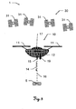
- FIG. 5 shows a target unit 10 according to the invention embodied by an aircraft 10, for example a drone with four drive units 11, in particular rotors, a receiving module 17 and a marking unit 15, wherein the marking unit 15 is mounted modularly detachable on the aircraft 10.
- the rotors 11 can be controlled such that by a respective orientation and / or a respective individually adjustable rotational speed, a floating positioning of the aircraft 10 at any point, for example, at a target position 6, can be positioned.
- the target position 6 can typically be vertical, ie in the direction parallel to the gravitational field of the earth, above a target point 5 to be marked.
- the reception module 17 can be designed, for example, to receive GNSS signals, GNSS correction signals and / or radio signals in order to determine the position make the target unit 10 feasible.
- the determination of the position of the target unit 10 can furthermore take place by means of a surveying station whose targeting unit can measure and track the target unit 10 or a reflector arranged on the target unit 10 and thus determine a distance and angle to the unit 10.
- the position and control information derivable in this way can be sent to the destination unit 10 and received there by the reception module 17.
- the marking unit 15 can have a laser beam source for emitting a target point 5 marking, optically visible laser beam 16 and / or other marking means, for example a spraying device for marking the point 5 by spraying a marking to mark the target point 5.
- a marking direction 14 of the marking unit 15, depending on the embodiment, for example the emission direction of the laser radiation 16 and / or a spray direction of the spraying device, can always be directed parallel to the direction of the perpendicular in the case of a cardan suspension of the marking unit 15.
- alignment means for aligning the marking direction 14, in particular defined alignable mirror, or for aligning the marking unit 15, in particular servomotors may be provided at a defined angle to the gravitational field or gravitational vector.
- a pivoting of the marking direction 14 or the marking unit 15 can take place in up to three axes.
- the destination unit 10 can have a device for distance measurement 15a for an object, in particular for the destination point 5.
- the distance measuring device 15a can in turn be aligned by further alignment means, in particular in three axes, to a point to be measured.
- a distance measurement by means of the laser beam 16 can be carried out for marking.
- an image or an image sequence of a measurement environment can be detected, stored and / or transmitted via a transmitter to a remote control of the target unit 10 and displayed there on a display.
- This image may facilitate a user's control of the aircraft or allow accurate positioning.
- image processing of an image sequence a movement or a path along which the destination unit 10 moves can be derived.
- FIG. 6 is the inventive aircraft 10 (target unit) off FIG. 5 shown, wherein further a positioning sequence for reaching a target position 6 with the target unit 10 is shown.
- the target unit 10 is here at a current actual position 4. Depending on the actual position 4 and a known position of the target point 5, the target unit 10 can be positioned in a target position 6. A control of the movement of the target unit 10 toward this target position 6 can take place by means of the rotors 11, for which purpose signals are received by the receiving module 17. To mark the target point 5, in turn, the marking unit 15 is provided.
- further waypoints 7 may be predetermined and / or, in particular automatically, determined from a terrain model, along which the destination unit 10 can move.
- the terrain model may include information about the terrain, such as terrain vegetation and / or positions and dimensions of buildings, from a geodetic information database.
- a path 8, in particular a trajectory, for a movement of the target unit 10 may be defined such that already known obstacles in the motion environment can be considered and circumvented.
- FIG. 7 1 shows a determination according to the invention of the orientation of the marking direction 14a, 14b represented by the laser beams 16a, 16b of the marking unit 15 of the target unit 10.
- the target unit 10 is here already-controlled by the signals received by the receiving module 17 and by the rotors 11-floating in one Target position 6 is positioned. If the coordinates of the position of the target point 5a, 5b in three dimensions are known, the alignment angles for the marking direction 14a, 14b can be calculated from the target position 6 and the alignment of the target unit 10 and the target point position 5a, 5b. If, on the other hand, only the horizontal coordinates of the target point 5a, 5b are known, it is not possible to unambiguously determine the orientation of the marking direction 14a, 14b from this information.
- a digital terrain model can additionally be used for the calculation.
- terrain surfaces 60a, 60b can be cut with a vertical axis 60 defining the horizontal position, and the target point positions 5a, 5b can be determined from the intersection points.
- An alignment of the laser radiation 16a, 16b can then take place taking into account the target point positions 5a, 5b.
- a distance to the marked target point 5a, 5b can be measured by means of a distance measuring device arranged on the target unit 10. From the known position of the target unit 10 and the measured distance with known orientation of the marking direction 14a, 14b, a correct marking of the target point 5a, 5b can thus be checked.
- the target point 5a, 5b or the vertical position of the point 5a, 5b by a section of the vertical axis 61 and the laser radiation 16a, 16b, taking into account a calculated target distance, in response to an angle between the marking direction 14a, 14b and vertical axis 61 can be determined, from the destination unit 10 to the destination point 5a, 5b.
Landscapes
- Engineering & Computer Science (AREA)
- Radar, Positioning & Navigation (AREA)
- Remote Sensing (AREA)
- Physics & Mathematics (AREA)
- General Physics & Mathematics (AREA)
- Computer Networks & Wireless Communication (AREA)
- Aviation & Aerospace Engineering (AREA)
- Automation & Control Theory (AREA)
- Electromagnetism (AREA)
- Position Fixing By Use Of Radio Waves (AREA)
- Navigation (AREA)
- Control Of Position, Course, Altitude, Or Attitude Of Moving Bodies (AREA)
Claims (15)
- Système de marquage géodésique (1) pour le marquage d'un point de mire connu (5, 5a, 5b) avec une unité de cible pouvant être commandée à distance, mobile de manière autonome, sans conducteur (10) et avec un dispositif de détermination de position géodésique (20, 30, 40) pour déterminer la position réelle extérieure de l'unité de cible (10), cependant que l'unité de cible (10) est configurée de telle manière que l'unité de cible (10) peut être positionnée tout au moins temporairement en grande mesure en une position fixe, en particulier en flottant, cependant que• l'unité de cible (10) porte une unité de marquage (15), en particulier amovible à la manière d'un module, pour le marquage du point de mire (5, 5a, 5b) et• le système de marquage (1) présente une unité de commande, cependant que l'unité de commande est configurée de telle manièrecaractérisé en ce que l'unité de cible (10) est une aéronef.∘ qu'en fonction de la position réelle extérieure (4), qui peut être déterminée en particulier en continu, et d'une position de point de mire connue du point de mire (5, 5a, 5b) l'unité de cible (10) peut être positionnée en étant commandée automatiquement, en particulier en continu, dans une position de consigne définie (6), en particulier dans une plage de tolérance définie autour de la position de consigne (6), par rapport à la position du point de mire et∘ qu'en tenant compte de la position réelle (4), de la position de consigne (6) et d'une direction de marquage définie (14, 14a, 14b) de l'unité de marquage (15) par rapport au point de mire (5, 5a, 5b), l'unité de marquage (15) peut être commandée pour le marquage du point de mire (5, 5a, 5b) si bien que le point de mire (5, 5a, 5b) peut être marqué dans la direction de marquage définie (14, 14a, 14b) avec une précision géodésique,
- Système de marquage (1) selon la revendication 1, caractérisé en ce que• le dispositif de détermination de position (20, 30, 40) présente au moins une unité émettrice pour émettre des signaux de positionnement et• l'aéronef (10) est configurée de telle manière que les signaux de positionnement peuvent être reçus, en particulier au moyen d'une antenne GNSS, et la position réelle (4) de l'aéronef (10) peut être déterminée à partir des signaux de positionnement,en particulier cependant que• l'unité émettrice est configurée comme un émetteur GNSS, en particulier un satellite GNSS (31), en particulier un satellite GPS, GLONASS ou Galileo et que les signaux de positionnement sont matérialisés par des signaux GNSS ou• l'unité émettrice présente un module de pseudo-satellite et les signaux de positionnement sont matérialisés par des signaux de pseudo-satellite,en particulier cependant que• le dispositif de détermination de position (20, 30, 40) présente une station de référence GNSS (40) pour l'émission de signaux de correction GNSS (41) et• l'aéronef (10) est configurée de telle manière que les signaux de correction GNSS (41) peuvent être reçus et la position réelle de l'aéronef (10) peut être déterminée à partir des signaux GNSS reçus et les signaux de correction GNSS.
- Système de marquage (1) selon l'une des revendications 1 ou 2, caractérisé en ce que• l'aéronef (10) présente un réflecteur (21),• le dispositif de détermination de position (20, 30, 40) présente un appareil de mesure géodésique (20), en particulier un théodolite ou une station totale, avec au moins∘ un dispositif de visée (25), en particulier une lunette de visée, cependant que le dispositif de visée (25) est pivotant, en particulier de manière motorisée, par rapport à une base (23) de l'appareil de mesure pour modifier l'orientation de celui-ci et présente au moins
une unité d'émission qui définit un axe de visée optique et une source de rayonnement pour l'émission d'un faisceau de mesure optique (22) pour la mesure de la distance parallèlement, en particulier coaxialement, par rapport à l'axe de visée optique,∘ une fonctionnalité de mesure d'angle pour la détection de haute prévision de l'orientation de l'axe de visée et∘ des moyens d'évaluation pour le stockage de données et la commande de l'orientation du dispositif de visée et• le faisceau de mesure (22) peut être orienté sur le réflecteur (21) si bien que la position réelle (4) de l'aéronef (10) peut être déterminéeen particulier cependant• qu'un signal qui peut être transmis à l'aéronef (10), en particulier cependant que le signal est matérialisé par un signal radio, un signal modulé sur un faisceau laser ou un signal électronique, présente• une information de position, cependant que l'information de position peut être convertie en données de commande dans une première unité de traitement associée à l'aéronef (10) ou• les données de commande, cependant que les données de commande peuvent être déterminées à partir de l'information de position au moyen d'une seconde unité de traitement associée à l'appareil de mesure (20). - Système de marquage (1) selon l'une des revendications 1 à 3, caractérisé en ce que l'aéronef (10) présente une unité de capteur (12) pour déterminer une orientation et/ou la position réelle de l'aéronef (10), en particulier un capteur d'inclinaison, un magnétomètre, un capteur d'accélération, un capteur de vitesse de rotation et/ou un capteur de vitesse
et/ou
l'aéronef (10) présente un composant qui indique l'orientation de l'aéronef (10) et le système de marquage (1) présente un dispositif de saisie, en particulier une caméra, pour la saisie et/ou la visée du composant et pour déterminer l'orientation de l'aéronef (10) à partir de la position et de l'arrangement du composant
et/ou
l'aéronef (10) peut être positionnée au moins temporairement en grande mesure en une position fixe horizontal, en particulier en flottant, cependant qu'une action sur le positionnement due à des influences extérieures, en particulier à l'écoulement de l'air, à des variations de pression et/ou de température, peut être compensée dans le sens vertical
et/ou
le système de marquage (1) présente une unité de télécommande pour la commande de l'aéronef (10), en particulier cependant que l'unité de télécommande présente un affichage pour la représentation d'informations. - Système de marquage (1) selon la revendication 4, caractérisé en ce que le système de marquage (1) présente une fonctionnalité de réglage, cependant que, lors de l'exécution de la fonctionnalité de réglage, la position réelle de l'aéronef (1) est déterminée en continu en étant commandée par l'unité de commande pendant une fenêtre de temps de marquage• au moyen d'une interaction de l'appareil de mesure géodésique (20) avec le réflecteur (21)
et/ou• au moyen de l'unité de capteur (12),et l'aéronef (10) est maintenue stable en se basant sur celle-ci de telle manière que le point de mire (5, 5a, 5b) est marqué en continu pendant toute la fenêtre du temps de marquage au moyen de l'unité de marquage (15) avec une précision géodésique, en particulier cependant que• le positionnement de l'aéronef (10) est réglé de telle manière que l'aéronef (10) se trouve pendant toute la fenêtre du temps de marquage dans la position de consigne (6) et/ou• la direction de marquage (14, 14a, 14b) est adaptée en continu et/ou• un message d'erreur est émis si le marquage du point de mire (5, 5a, 5b) n'est pas effectué au moins temporairement. - Procédé pour commander un marquage qui est effectué avec une précision géodésique d'un point de mire connu (5, 5a, 5b) avec une unité de cible pouvant être commandée à distance, mobile de manière autonome, sans conducteur (10), cependant qu'une position réelle extérieure (4) de l'unité de cible (10) est déterminée, en particulier en continu, cependant que• l'unité de cible (10) porte une unité de marquage (15), en particulier amovible à la manière d'un module, pour le marquage du point de mire (5, 5a, 5b) et• qu'en fonction de la position réelle extérieure (4), qui peut être déterminée en particulier en continu, et d'une position de point de mire connue du point de mire (5, 5a, 5b) l'unité de cible (10) peut être positionnée en étant commandée automatiquement, en particulier en continu, dans une position de consigne définie (6), en particulier dans une plage de tolérance définie autour de la position de consigne (6), par rapport à la position du point de mire et• qu'en tenant compte de la position réelle (4), de la position de consigne (6) et d'une direction de marquage définie (14, 14a, 14b) de l'unité de marquage (15) par rapport au point de mire (5, 5a, 5b), l'unité de marquage (15) est commandée pour le marquage du point de mire (5, 5a, 5b) si bien que le point de mire (5, 5a, 5b) est marqué dans la direction de marquage définie (14, 14a, 14b) avec une précision géodésique, caractérisé en ce que l'unité de cible (10) est une aéronef.
- Procédé pour la commande du marquage selon la revendication 6, caractérisé en ce que, dans le cadre du procédé, des signaux de positionnement sont reçus par l'aéronef (10) et la position réelle extérieure (4), en particulier une orientation de l'aéronef (10), est déterminée à partir des signaux de positionnement, en particulier cependant que les signaux de positionnement sont matérialisés par des signaux GNSS, des signaux de pseudo-satellite et/ou des signaux de correction GNSS et la position réelle (4) est déterminée à partir des signaux GNSS et/ou des signaux semblables à des signaux GNSS, en particulier en tenant compte des signaux de correction GNSS et/ou un faisceau de mesure (22) est réfléchi du côté de l'aéronef et la position réelle extérieure (4) est déterminée au moyen du faisceau de mesure réfléchi (22).
- Procédé pour commander le marquage selon l'une des revendications 6 ou 7, caractérisé en ce que l'orientation de l'aéronef (10) est déterminée en particulier dans la direction du roulis, de tangage et de lacet, et/ou une distance par rapport à un objet, en particulier par rapport à un obstacle, est déterminée
et/ou une image est saisie, en particulier cependant que l'image présente le point de mire (5, 5a, 5b) et/ou le marquage du point de mire (5, 5a, 5b) se fait avec un rayonnement visible optiquement (16, 16a, 16b) et une direction du rayonnement se situe parallèlement, en particulier coaxialement, par rapport à la direction de marquage (14, 14a, 14b) et/ou la direction de marquage (14, 14a, 14b) de l'unité de marquage (15) est orientée parallèlement, en particulier automatiquement, à la verticale et/ou de manière définie par rapport à l'orientation de l'aéronef (10), en particulier cependant que l'unité de marquage (15) est suspendue à la Cardan et/ou l'aéronef (10) présente des moyens d'alignement pour l'alignement défini de la direction de marquage (14, 14a, 14b), en particulier cependant que l'unité de marquage (15) est pivotée dans deux, en particulier dans trois axes. - Procédé pour commander le marquage selon l'une des revendications 6 à 8, caractérisé en ce que, dans le cadre d'un réglage pendant une fenêtre de temps de marquage, la position réelle de l'aéronef (10) est déterminée en continu• au moyen du faisceau de mesure (22) réfléchi du côté de l'aéronef ou• au moyen d'une unité de capteur (12) pour déterminer une orientation et/ou la position réelle de l'aéronef (10),et l'aéronef (10) est maintenue stable en se basant sur celle-ci de telle manière que le point de mire (5, 5a, 5b) est marqué en continu pendant toute la fenêtre du temps de marquage au moyen de l'unité de marquage (15) avec une précision géodésique, en particulier cependant que• le positionnement de l'aéronef (10) est réglé de telle manière que l'aéronef (10) se trouve pendant toute la fenêtre du temps de marquage dans la position de consigne (6) et/ou• la direction de marquage (14, 14a, 14b) est adaptée en continu et/ou• un message d'erreur est émis si le marquage de la cible (5, 5a, 5b) n'est pas effectué au moins temporairementdans le cadre du procédé un itinéraire (8) est défini par des points de passage (7), cependant que l'aéronef (10) est déplacée le long de l'itinéraire (8), en particulier cependant qu'une optimisation d'un trajet est effectuée, en particulier automatiquement et/ou l'itinéraire (8) présente le point de mire (5, 5a, 5b) et/ou la position de consigne (6) et/ou un marquage de la position des points de passage (7) comme points de mire intermédiaires est effectué en continu le long de l'itinéraire et/ou des informations et/ou des commandes, en particulier la position du point de mire, sont entrées dans l'aéronef (10) et/ou des informations, en particulier l'image saisie, sont sorties, en particulier sur un affichage.
et/ou - Aéronef pouvant être commandée à distance, mobile de manière autonome, sans conducteur (10), en particulier drone, pour l'utilisation dans un système de marquage (1) selon l'une des revendications 1 à 5, cependant que• l'aéronef (10) est configurée de telle manière que l'aéronef (10) peut être positionnée tout au moins temporairement en grande mesure en une position fixe, en particulier en flottant, et• des informations de position pour déterminer une position réelle extérieure (4) de l'aéronef (10) et pour générer des données de commande et/ou les données de commande peuvent être transmises directement à l'aéronef (10),caractérisée en ce que• l'aéronef (10) porte une unité de marquage (15) pour le marquage d'un point de mire (5, 5a, 5b), en particulier cependant que l'unité de marquage (15) est réalisée amovible à la manière d'un module et• les données de commande sont configurées telles∘ qu'en fonction de la position réelle extérieure (4), qui peut être déterminée en particulier en continu, et d'une position de point de mire connue du point de mire (5, 5a, 5b) l'aéronef (10) peut être positionnée en étant commandée automatiquement, en particulier en continu, dans une position de consigne définie (6), en particulier dans une plage de tolérance définie autour de la position de consigne (6), par rapport à la position du point de mire et∘ qu'en tenant compte de la position réelle (4), de la position de consigne (6) et d'une direction de marquage définie (14, 14a, 14b) de l'unité de marquage (15) par rapport au point de mire (5, 5a, 5b), l'unité de marquage (15) peut être commandée pour le marquage du point de mire (5, 5a, 5b) si bien que le point de mire (5, 5a, 5b) peut être marqué dans la direction de marquage définie (14, 14a, 14b) avec une précision géodésique.
- Aéronef (10) selon la revendication 10 pour l'utilisation dans un système de marquage (1) selon l'une des revendications 1 à 5, caractérisée en ce que l'aéronef (10) présente un récepteur (17, 42) pour des signaux de positionnement, en particulier une antenne GNSS, et une unité de traitement pour déterminer une position réelle (4) de l'aéronef (10) à partir des signaux de positionnement, en particulier cependant que les signaux de positionnement sont représentés par des signaux GNSS, en particulier cependant que les signaux GNSS sont matérialisés par des signaux GPS, des signaux GLONASS ou des signaux Galileo, des signaux de pseudo-satellite et/ou des signaux de correction GNSS et la position réelle (4) est déterminée à partir des signaux GNSS et/ou des signaux semblables à des signaux GNSS, en particulier en tenant compte des signaux de correction GNSS et/ou l'aéronef (10) présente un réflecteur (21).
- Aéronef (10) selon l'une des revendications 10 ou 11 pour l'utilisation dans un système de marquage (1) selon l'une des revendications 1 à 5, caractérisée en ce que l'aéronef (10) présente une unité de capteur (12) pour déterminer une orientation et/ou la position réelle de l'aéronef (10), en particulier un capteur d'inclinaison, un magnétomètre, un capteur d'accélération, un capteur de vitesse de rotation et/ou un capteur de vitesse et/ou l'aéronef (10) présente un capteur pour la mesure de la distance (13) par rapport à des objets, en particulier un radar
et/ou l'aéronef (10) présente une unité de saisie optique (19), en particulier une caméra, pour la saisie d'une image, en particulier cependant que l'image présente le point de mire (5, 5a, 5b) et/ou l'aéronef (10) présente, pour l'alignement défini, en particulier pour l'alignement parallèle automatiquement par rapport à la verticale, de la direction de marquage (14, 14a, 14b), une suspension à la Cardan et/ou des moyens d'alignement pour l'unité de marquage (15), en particulier cependant que l'unité de marquage (15) peut pivoter dans deux axes, en particulier dans trois axes et/ou l'unité de marquage (15) présente une source de rayonnement pour l'émission d'un faisceau visible optiquement (16, 16a, 16b) et la source de rayonnement est placée de telle manière qu'une direction d'émission du rayonnement optique est parallèle, en particulier coaxiale, à la direction de marquage (14, 14a, 14b)
et/ou l'aéronef (10) présente une unité d'entrée, en particulier un clavier, un affichage tactile et/ou une interface de données pour l'entrée d'informations et/ou de commandes, en particulier de la position du point de mire et/ou l'aéronef (10) présente une unité de sortie, en particulier un affichage, pour la sortie d'informations, en particulier de l'image saisie par la caméra et/ou l'aéronef (10) présente une télécommande pour la commande de l'aéronef (10), en particulier cependant que la télécommande présente un affichage pour la représentation d'informations et/ou de l'image saisie par la caméra. - Dispositif de marquage pour le marquage d'un point de mire connu (5, 5a, 5b) et pour l'utilisation dans un système de marquage (1) selon l'une des revendications 1 à 5, cependant que le dispositif de marquage comprend :• l'unité de marquage qui peut être télécommandée (15) et• le dispositif de détermination de position géodésique (20, 30, 40), en particulier un théodolite ou une station totale, pour la détermination de la position extérieure de l'unité de marquage (15)et cependant qu'une position réelle extérieure (4) de l'unité de marquage (15) peut être déterminée, en particulier en continu, au moyen du dispositif de détermination de position (20, 30, 40),
cependant que• l'unité de marquage (15) présente une interface de données, en particulier un module radio, une interface de Bluetooth, une interface infrarouge et/ou un Com-Port, pour la commande et/ou pour l'échange d'informations avec une unité de cible pouvant être commandée à distance, mobile de manière autonome, sans conducteur (10) et• le dispositif de marquage présente une unité de commande, cependant que l'unité de commande est configurée de telle manièrecaractérisé en ce que l'unité de cible (10) est une aéronef.∘ qu'en fonction de la position réelle extérieure (4), qui peut être déterminée en particulier en continu, et d'une position de point de mire connue du point de mire (5, 5a, 5b) l'unité de marquage (15) peut être positionnée, en particulier en continu, dans une position de consigne définie (6), en particulier dans une plage de tolérance définie autour de la position de consigne (6), par rapport à la position du point de mire et∘ qu'en tenant compte de la position réelle (4), de la position de consigne (6) et d'une direction de marquage définie (14, 14a, 14b) de l'unité de marquage (15) par rapport au point de mire, l'unité de marquage peut être commandée si bien que le point de mire (5, 5a, 5b) peut être marqué dans la direction de marquage définie (14, 14a, 14b) avec une précision géodésique, - Dispositif de marquage pour le marquage d'un point de mire connu (5, 5a, 5b) selon la revendication 13 pour l'utilisation dans un système de marquage (1) selon l'une des revendications 1 à 5,
caractérisé en ce que• le dispositif de détermination de position (20, 30, 40) présente au moins une unité d'émission pour l'émission de signaux de positionnement et• l'unité de marquage (15) est configurée de telle manière que les signaux de positionnement peuvent être reçus, en particulier au moyen d'une antenne GNSS, et que la position réelle (4) de l'unité de marquage (15) peut être déterminée à partir des signaux de positionnement,en particulier cependant que• l'unité émettrice est configurée comme un émetteur GNSS, en particulier un satellite GNSS (31), en particulier un satellite GPS, GLONASS ou Galileo et que les signaux de positionnement sont matérialisés par des signaux GNSS ou• l'unité émettrice présente un module de pseudo-satellite et les signaux de positionnement sont matérialisés par des signaux de pseudo-satellite, en particulier cependant que• le dispositif de détermination de position (20, 30, 40) présente une station de référence GNSS (40) pour l'émission de signaux de correction GNSS (41) et• l'unité de marquage (15) est configurée de telle manière que les signaux de correction GNSS (41) peuvent être reçus et la position réelle (4) de l'unité de marquage (15) peut être déterminée à partir des signaux GNSS reçus et des signaux de correction GNSS
et/ou
le dispositif de détermination de position (20, 30, 40) présente un appareil de mesure géodésique (20), en particulier un théodolite ou une station totale, cependant que la position de l'unité de marquage (15) est indiquée de manière très précise dans l'espace par un réflecteur (21), avec au moins• un dispositif de visée (25), en particulier une lunette de visée, cependant que le dispositif de visée (25) est pivotant, en particulier de manière motorisée, par rapport à une base (23) de l'appareil de mesure (20) pour modifier l'orientation de celui-ci et présente au moins∘ une unité d'émission qui définit un axe de visée optique et∘ une source de rayonnement pour l'émission d'un faisceau de mesure optique (22) parallèlement, en particulier coaxialement, par rapport à l'axe de visée optique, pour la mesure de la distance,• une fonctionnalité de mesure d'angle pour la détection de haute prévision de l'orientation de l'axe de visée et• des moyens d'évaluation pour le stockage de données et la commande de l'orientation du dispositif de viséeet cependant que le faisceau de mesure (22) peut être orienté sur le réflecteur (21) si bien que la position réelle (4) de l'unité de marquage (15) peut être déterminée. - Produit programme d'ordinateur qui est stocké sur un support lisible par une machine ou signal de données d'ordinateur, incorporé par une onde électromagnétique, avec un code de programme pour réaliser le procédé selon l'une quelconque des revendications 6 à 9, en particulier lorsque le programme est exécuté dans une unité électronique de traitement de données.
Priority Applications (1)
| Application Number | Priority Date | Filing Date | Title |
|---|---|---|---|
| EP12714697.5A EP2697606B1 (fr) | 2011-04-14 | 2012-04-13 | Système géodésique pour marquer des points de mire |
Applications Claiming Priority (3)
| Application Number | Priority Date | Filing Date | Title |
|---|---|---|---|
| EP11162509A EP2511659A1 (fr) | 2011-04-14 | 2011-04-14 | Système de marquage géodésique pour le marquage de points de mire |
| EP12714697.5A EP2697606B1 (fr) | 2011-04-14 | 2012-04-13 | Système géodésique pour marquer des points de mire |
| PCT/EP2012/056757 WO2012140188A1 (fr) | 2011-04-14 | 2012-04-13 | Système de marquage géodésique pour le marquage de points de mire |
Publications (2)
| Publication Number | Publication Date |
|---|---|
| EP2697606A1 EP2697606A1 (fr) | 2014-02-19 |
| EP2697606B1 true EP2697606B1 (fr) | 2016-11-30 |
Family
ID=44501736
Family Applications (2)
| Application Number | Title | Priority Date | Filing Date |
|---|---|---|---|
| EP11162509A Withdrawn EP2511659A1 (fr) | 2011-04-14 | 2011-04-14 | Système de marquage géodésique pour le marquage de points de mire |
| EP12714697.5A Active EP2697606B1 (fr) | 2011-04-14 | 2012-04-13 | Système géodésique pour marquer des points de mire |
Family Applications Before (1)
| Application Number | Title | Priority Date | Filing Date |
|---|---|---|---|
| EP11162509A Withdrawn EP2511659A1 (fr) | 2011-04-14 | 2011-04-14 | Système de marquage géodésique pour le marquage de points de mire |
Country Status (8)
| Country | Link |
|---|---|
| US (1) | US9233751B2 (fr) |
| EP (2) | EP2511659A1 (fr) |
| KR (1) | KR101632244B1 (fr) |
| CN (1) | CN103477189B (fr) |
| AU (1) | AU2012241777B2 (fr) |
| BR (1) | BR112013026034A2 (fr) |
| CA (1) | CA2833184C (fr) |
| WO (1) | WO2012140188A1 (fr) |
Families Citing this family (107)
| Publication number | Priority date | Publication date | Assignee | Title |
|---|---|---|---|---|
| EP2511658A1 (fr) * | 2011-04-14 | 2012-10-17 | Hexagon Technology Center GmbH | Système de mesure et procédé de détermination de nouveau point |
| EP2511659A1 (fr) * | 2011-04-14 | 2012-10-17 | Hexagon Technology Center GmbH | Système de marquage géodésique pour le marquage de points de mire |
| WO2013019665A1 (fr) * | 2011-07-29 | 2013-02-07 | Gammex, Inc. | Système laser informatique amovible pour positionnement radiographique d'un patient |
| ES2525921T3 (es) * | 2012-08-13 | 2015-01-02 | Bauer Spezialtiefbau Gmbh | Procedimiento y dispositivo para producir y medir una perforación |
| US9002719B2 (en) | 2012-10-08 | 2015-04-07 | State Farm Mutual Automobile Insurance Company | Device and method for building claim assessment |
| US9082015B2 (en) | 2013-03-15 | 2015-07-14 | State Farm Mutual Automobile Insurance Company | Automatic building assessment |
| US8872818B2 (en) | 2013-03-15 | 2014-10-28 | State Farm Mutual Automobile Insurance Company | Methods and systems for capturing the condition of a physical structure |
| US8756085B1 (en) | 2013-03-15 | 2014-06-17 | State Farm Mutual Automobile Insurance Company | Systems and methods for assessing property damage |
| US8818572B1 (en) | 2013-03-15 | 2014-08-26 | State Farm Mutual Automobile Insurance Company | System and method for controlling a remote aerial device for up-close inspection |
| DE102013211414A1 (de) | 2013-06-18 | 2014-12-18 | Kuka Laboratories Gmbh | Fahrerloses Transportfahrzeug und Verfahren zum Betreiben einesfahrerlosen Transportfahrzeugs |
| CN103543751A (zh) * | 2013-09-12 | 2014-01-29 | 深圳市大疆创新科技有限公司 | 无人飞行器的控制装置及无人飞行器 |
| JP6302660B2 (ja) * | 2013-12-16 | 2018-03-28 | 株式会社ニコン・トリンブル | 情報取得システム、無人飛行体制御装置 |
| EP2902802B1 (fr) * | 2014-01-31 | 2016-10-26 | S.M.S. Smart Microwave Sensors GmbH | Dispositif de détection |
| US9581443B2 (en) | 2014-03-17 | 2017-02-28 | Ronald D. Shaw | Surveying system |
| US10078136B2 (en) * | 2014-03-25 | 2018-09-18 | Amazon Technologies, Inc. | Sense and avoid for automated mobile vehicles |
| DE102015105070A1 (de) * | 2014-06-11 | 2015-12-17 | Rheinmetall Defence Electronics Gmbh | Vorrichtung und System zur Darstellung von Treffern von Geschossen und/oder Raketen sowie Verfahren dazu |
| JP6290735B2 (ja) * | 2014-07-11 | 2018-03-07 | 株式会社パスコ | 測量方法 |
| US10459105B2 (en) * | 2014-07-17 | 2019-10-29 | The Charles Machine Works, Inc. | Airborne locator of an underground object |
| US10877176B2 (en) | 2014-07-17 | 2020-12-29 | The Charles Machine Works, Inc. | Airborne locator of an underground object |
| WO2016019356A1 (fr) | 2014-08-01 | 2016-02-04 | Shaw Ronald D | Système de couverture |
| US12078737B2 (en) | 2014-08-01 | 2024-09-03 | Jesse Gil | Surveying system |
| EP3021079B1 (fr) * | 2014-11-14 | 2017-03-01 | Leica Geosystems AG | Système de relevé géodésique avec une visualisation de la liste des tâches |
| EP3021078B1 (fr) * | 2014-11-14 | 2018-09-26 | Leica Geosystems AG | Système de relevé géodésique avec une caméra virtuelle |
| EP3029488B1 (fr) | 2014-12-04 | 2019-02-27 | Hexagon Technology Center GmbH | Télémètre équipé d'une source lumineuse de type laser |
| EP3034995B1 (fr) * | 2014-12-19 | 2024-02-28 | Leica Geosystems AG | Procédé de détermination d'un décalage d'orientation ou de position d'un appareil de mesure géodésique et appareil de mesure correspondant |
| EP3037779A1 (fr) * | 2014-12-23 | 2016-06-29 | HILTI Aktiengesellschaft | Procédé de transfert d'un objet sur une surface limite |
| US10066935B2 (en) * | 2015-01-21 | 2018-09-04 | Trimble Kaiserslautern Gmbh | Laser device and laser beam detector for detecting light of a laser device |
| EP3062066B1 (fr) * | 2015-02-26 | 2025-01-15 | Hexagon Technology Center GmbH | Détermination de données d'objet à l'aide d'une commande UAV basée sur un modèle |
| US10162353B2 (en) | 2015-03-03 | 2018-12-25 | PreNav, Inc. | Scanning environments and tracking unmanned aerial vehicles |
| EP3086283B1 (fr) * | 2015-04-21 | 2019-01-16 | Hexagon Technology Center GmbH | Fourniture d'un nuage de points à l'aide d'un instrument de surveillance et un dispositif de caméra |
| EP3093616A1 (fr) * | 2015-05-13 | 2016-11-16 | Centre National d'Etudes Spatiales | Dispositif et procédé pour désigner des points caractéristiques |
| US10048069B2 (en) | 2015-07-17 | 2018-08-14 | Raul Romero | Utility locating tool |
| EP3353706A4 (fr) * | 2015-09-15 | 2019-05-08 | SZ DJI Technology Co., Ltd. | Système et procédé de prise en charge de suivi de cible uniforme |
| WO2017071143A1 (fr) | 2015-10-30 | 2017-05-04 | SZ DJI Technology Co., Ltd. | Système et procédés de planification et de commande de trajectoire d'uav |
| CN106323229A (zh) * | 2015-10-10 | 2017-01-11 | 北京控制与电子技术研究所 | 一种基于卫星定向的定向经纬仪 |
| EP3168704B1 (fr) | 2015-11-12 | 2021-02-24 | Hexagon Technology Center GmbH | Inspection en 3d d'une surface au moyen de véhicules mobiles |
| IL242858A (en) | 2015-11-30 | 2017-04-30 | Elbit Systems Land & C4I Ltd | Autonomous vehicle control system |
| US9898638B2 (en) * | 2016-01-22 | 2018-02-20 | International Business Machines Corporation | Optical marker for delivery drone cargo delivery |
| US9592912B1 (en) * | 2016-03-08 | 2017-03-14 | Unmanned Innovation, Inc. | Ground control point assignment and determination system |
| US9903954B1 (en) | 2016-03-31 | 2018-02-27 | Rockwell Collins, Inc. | Systems and methods for absolute position navigation using pseudolites |
| US10176527B1 (en) | 2016-04-27 | 2019-01-08 | State Farm Mutual Automobile Insurance Company | Providing shade for optical detection of structural features |
| US9541633B2 (en) * | 2016-04-29 | 2017-01-10 | Caterpillar Inc. | Sensor calibration system |
| CN106454069B (zh) * | 2016-08-31 | 2019-11-08 | 歌尔股份有限公司 | 一种控制无人机拍摄的方法、装置和可穿戴设备 |
| JP6773503B2 (ja) * | 2016-09-27 | 2020-10-21 | 株式会社トプコン | レーザスキャナシステム及び点群データのレジストレーション方法 |
| AU2017204859B2 (en) * | 2016-10-04 | 2018-08-30 | HZW Holdings Pty Ltd | A gravimetry assembly |
| CN108251878B (zh) * | 2016-12-29 | 2019-12-20 | 中国空气动力研究与发展中心超高速空气动力研究所 | 一种双目前光定位的铝合金模型表面标记点制作方法 |
| CA3051425A1 (fr) | 2017-02-02 | 2018-08-09 | PreNav, Inc. | Collecte d'image de suivi pour capture numerique d'environnements, et systemes et procedes associes |
| JP6884003B2 (ja) * | 2017-02-20 | 2021-06-09 | 株式会社トプコン | 無人航空機の追跡装置、無人航空機の追跡方法、無人航空機の追跡システムおよびプログラム |
| JP2018146546A (ja) * | 2017-03-09 | 2018-09-20 | エアロセンス株式会社 | 情報処理システム、情報処理装置および情報処理方法 |
| EP3410063B1 (fr) * | 2017-05-31 | 2020-10-14 | Leica Geosystems AG | Relevé géodésique avec correction par rapport à l'inclinaison du dispositif |
| DE102017112931A1 (de) | 2017-06-13 | 2018-12-13 | Prüftechnik Dieter Busch Aktiengesellschaft | Mobiles Transportmittel zum Transportieren von Datensammlern, Datensammelsystem und Datensammelverfahren |
| US20190039720A1 (en) * | 2017-08-07 | 2019-02-07 | Bell Helicopter Textron Inc. | System and Method for Rotorcraft Approach to Hover |
| US10338592B2 (en) | 2017-08-24 | 2019-07-02 | Saudi Arabian Oil Company | High accuracy remote coordinate machine |
| JP7086554B2 (ja) * | 2017-09-29 | 2022-06-20 | 株式会社トプコン | 無人航空機の制御方法および無人航空機の制御用プログラム |
| US10831199B2 (en) * | 2017-09-29 | 2020-11-10 | Deere & Company | Using unmanned aerial vehicles to provide ground control points for aerial survey |
| US11709230B2 (en) * | 2017-10-12 | 2023-07-25 | John Matthews | Geodesic system and method of use |
| KR101881121B1 (ko) * | 2017-12-14 | 2018-07-23 | 주식회사 엠지아이티 | 거리를 측량하는 드론 및 드론의 제어 방법 |
| CN108415454B (zh) * | 2018-02-02 | 2021-04-27 | 特力惠信息科技股份有限公司 | 一种无人机实时交互判读的方法及终端 |
| JP7096022B2 (ja) * | 2018-03-22 | 2022-07-05 | 株式会社トプコン | Uavを用いた標点マーキングシステム |
| JP7139018B2 (ja) * | 2018-05-09 | 2022-09-20 | 株式会社日立プラントサービス | 自律走行型墨打ちロボット |
| JP7112978B2 (ja) * | 2018-05-15 | 2022-08-04 | 東邦ガスネットワーク株式会社 | 検査装置 |
| DE102018113244B3 (de) * | 2018-06-04 | 2019-11-07 | Deutsches Zentrum für Luft- und Raumfahrt e.V. | Verfahren und Vorrichtung zum Messen von Schwingungen eines Objekts unter Verwendung einer Drohne |
| US10768661B2 (en) * | 2018-06-13 | 2020-09-08 | Goodrich Corporation | Automatic orientation of a display of a portable aircraft cargo control and monitor panel |
| EP3833932A4 (fr) * | 2018-08-07 | 2022-05-04 | Civdrone Ltd. | Dispositif de vol stationnaire pour arpentage |
| EP3614101B1 (fr) | 2018-08-22 | 2021-03-31 | Leica Geosystems AG | Référencement de tâches de construction |
| US11397266B2 (en) | 2018-08-29 | 2022-07-26 | Subsite, Llc | GPS assisted walkover locating system and method |
| US11977378B2 (en) | 2018-09-17 | 2024-05-07 | The Charles Machine Works, Inc. | Virtual path guidance system |
| KR102123367B1 (ko) * | 2018-11-20 | 2020-06-16 | 주식회사 공간정보 | 간이 측정용 스마트 폴 드론 |
| US12296459B2 (en) | 2018-11-21 | 2025-05-13 | Dusty Robotics, Inc. | Mobile printing robot and related methods |
| CN109323656B (zh) * | 2018-11-24 | 2024-06-21 | 上海勘察设计研究院(集团)股份有限公司 | 一种用于点云配准的新型标靶及其提取算法 |
| EP3660451B1 (fr) | 2018-11-28 | 2022-04-27 | Hexagon Technology Center GmbH | Module de stationnement intelligent |
| KR102130655B1 (ko) * | 2018-11-30 | 2020-07-06 | 한국해양과학기술원 | 식별성이 향상된 지리정보 수정용 드론 |
| JP7051743B2 (ja) * | 2019-03-28 | 2022-04-11 | 東邦瓦斯株式会社 | 検査装置 |
| CA3076342A1 (fr) * | 2019-04-24 | 2020-10-24 | The Boeing Company | Alignement des capteurs sur les vehicules au moyen des sorties des capteurs |
| EP3734222B1 (fr) * | 2019-05-02 | 2024-12-11 | Leica Geosystems AG | Dispositif de mesure et/ou de délimitation de coordonnées |
| US11577397B2 (en) * | 2019-08-12 | 2023-02-14 | Dusty Robotics, Irc. | Position accuracy robotic printing system |
| AU2020346962A1 (en) | 2019-09-13 | 2022-03-31 | Dusty Robotics, Inc. | Mobile robot printing with wind protection |
| CN110550526B (zh) * | 2019-09-19 | 2020-12-25 | 日立楼宇技术(广州)有限公司 | 一种电梯钢丝绳的检测方法、装置及系统 |
| CN110806570B (zh) * | 2019-10-23 | 2022-04-05 | 成都飞机工业(集团)有限责任公司 | 一种激光跟踪仪温度误差补偿方法 |
| US11892559B2 (en) * | 2019-12-18 | 2024-02-06 | Rohde & Schwarz Gmbh & Co. Kg | Radar calibration system and method for moving a radar calibration target along a desired movement path |
| EP3855112A1 (fr) * | 2020-01-22 | 2021-07-28 | Leica Geosystems AG | Instrument géodésique comprenant une base et un module de relevé géodésique et/ou de projection |
| JP6975818B2 (ja) * | 2020-03-31 | 2021-12-01 | 西日本電信電話株式会社 | 位置情報取得システム、位置情報取得方法及びプログラム |
| EP3936817A1 (fr) * | 2020-07-08 | 2022-01-12 | Hexagon Technology Center GmbH | Télémètre à courte distance |
| EP3960389A1 (fr) * | 2020-08-24 | 2022-03-02 | Hilti Aktiengesellschaft | Système de marquage et procédé de marquage |
| WO2022059605A1 (fr) * | 2020-09-18 | 2022-03-24 | 富士フイルム株式会社 | Dispositif de détermination de position, procédé et programme de détermination de position et système de détermination de position |
| KR102200679B1 (ko) * | 2020-09-22 | 2021-01-11 | 주식회사 함께드론맵핑 | 거리측량 드론 |
| DE102020124832A1 (de) * | 2020-09-23 | 2022-03-24 | Hydromapper GmbH | Baugrubenvermessung |
| CN112229386A (zh) * | 2020-10-10 | 2021-01-15 | 王莉飞 | 一种工程勘探用定向距离检测设备及其检测方法 |
| US12252134B1 (en) | 2020-10-20 | 2025-03-18 | State Farm Mutual Automobile Insurance Company | Training and utilizing a machine-learning model to automatically predict an identity of a driver based on seat position |
| US11255669B1 (en) | 2020-11-12 | 2022-02-22 | Shadi Khnifes | Device and method for marking indicia on terrestrial surfaces in topographical surveying |
| KR102445618B1 (ko) * | 2020-11-25 | 2022-09-23 | 대한민국 | 벌집 제거용 드론 약액 살포 장치 및 이를 이용한 벌집 제거 방법 |
| JP2022087978A (ja) * | 2020-12-02 | 2022-06-14 | 三菱電機株式会社 | 位置姿勢算出装置、位置姿勢算出方法及び測量装置 |
| CN112558639A (zh) * | 2020-12-23 | 2021-03-26 | 苏州精英环保有限公司 | 一种用于大型污染场地调查采样点定位的装置 |
| US11668568B2 (en) * | 2021-05-14 | 2023-06-06 | Jason Kosmos | Survey marking rod |
| US12442633B2 (en) * | 2021-06-11 | 2025-10-14 | Nikon Corporation | Position measurement device and position measurement method |
| KR20240022533A (ko) * | 2021-06-11 | 2024-02-20 | 가부시키가이샤 니콘 | 위치 측정 장치, 위치 측정 시스템, 및 측정 장치 |
| US12078053B2 (en) | 2021-08-09 | 2024-09-03 | The Charles Machine Works, Inc. | Null point depth calibration |
| KR102346368B1 (ko) * | 2021-09-10 | 2022-01-03 | 주식회사 함께드론맵핑 | 측량수단의 이동에 따른 수평유지가 용이한 거리측량 드론 |
| US12517242B2 (en) | 2022-03-30 | 2026-01-06 | The Charles Machine Works, Inc. | Autonomous horizontal directional drilling (“HDD”) tracking system with rover |
| CN114623852B (zh) * | 2022-04-02 | 2023-03-24 | 杭州通泰测绘有限公司 | 基于测绘工程用全站仪监测的辅助防护设备 |
| DE102022117041A1 (de) | 2022-07-08 | 2024-01-11 | Universität Stuttgart, Körperschaft Des Öffentlichen Rechts | Laseranordnung und Verfahren zur Bearbeitung von Objekten mittels eines Laserstrahls |
| US12196873B1 (en) * | 2023-05-31 | 2025-01-14 | SB Technology, Inc. | Differentiated multi-agent navigation |
| US12228406B2 (en) * | 2023-05-31 | 2025-02-18 | SB Technology, Inc. | Multi-agent navigation |
| GB2636149A (en) * | 2023-11-30 | 2025-06-11 | Protech Innovations Ltd | Apparatus and methods of monitoring a location of an object |
| CN118009999B (zh) * | 2024-04-10 | 2024-06-07 | 贵州省地质矿产勘查开发局一O五地质大队 | 一种遥感测绘用标识装置 |
| US12152879B1 (en) * | 2024-07-30 | 2024-11-26 | Rigoberto Renteria | Layout marking system for tracing reference regions in a construction layout and a method thereof |
| CN119659724B (zh) * | 2025-02-21 | 2025-05-06 | 福建省交通科研院有限公司 | 一种道路与铁路交叉安全防控系统 |
Citations (4)
| Publication number | Priority date | Publication date | Assignee | Title |
|---|---|---|---|---|
| DE10246781A1 (de) * | 2002-10-08 | 2004-04-22 | Stotz-Feinmesstechnik Gmbh | Verfahren und Vorrichtung zur dreidimensionalen Vermessung von Objekten |
| US20060023204A1 (en) * | 2004-07-28 | 2006-02-02 | Zoltan Filep | Laser-GPS marking and targeting system |
| EP1703300A1 (fr) * | 2005-03-17 | 2006-09-20 | Leica Geosystems AG | Procédé et dispositif pour déterminer la position et l'orientation d'un objet |
| WO2008124713A2 (fr) * | 2007-04-09 | 2008-10-16 | Sam Stathis | Système et procédé capables de naviguer et/ou de mapper tout espace multidimensionnel |
Family Cites Families (29)
| Publication number | Priority date | Publication date | Assignee | Title |
|---|---|---|---|---|
| US5100229A (en) * | 1990-08-17 | 1992-03-31 | Spatial Positioning Systems, Inc. | Spatial positioning system |
| DE19710722C2 (de) | 1996-03-15 | 2003-06-05 | Pentax Corp | Automatische Fokussiereinrichtung für ein Fernrohr |
| DE19726706A1 (de) | 1997-06-24 | 1999-01-07 | Henkel Ecolab Gmbh & Co Ohg | Rührflügelantrieb für Pastenbehälter |
| DK1017721T3 (da) | 1997-09-16 | 2009-04-20 | Univ Oregon Health & Science | Rekombinante MHC molekyler, der kan anvendes til manipulation af antigenspecifikke T-celler |
| DE19812609C2 (de) | 1998-03-23 | 2001-12-13 | Leica Geosystems Ag | Verfahren zur Bestimmung der Position und Drehlage eines Objektes |
| JP3174551B2 (ja) | 1998-06-11 | 2001-06-11 | 旭光学工業株式会社 | 焦点調節レンズ位置検出装置 |
| JP3500077B2 (ja) | 1998-10-14 | 2004-02-23 | ペンタックス株式会社 | 視準望遠鏡の自動焦点調節機構 |
| US6836285B1 (en) * | 1999-09-03 | 2004-12-28 | Arete Associates | Lidar with streak-tube imaging,including hazard detection in marine applications; related optics |
| JP5037765B2 (ja) | 2001-09-07 | 2012-10-03 | 株式会社トプコン | オペレータ誘導システム |
| AU2003207799A1 (en) * | 2002-02-04 | 2003-09-02 | Bae Systems Information And Electronic Systems Integration Inc. | Reentry vehicle interceptor with ir and variable fov laser radar |
| US7095488B2 (en) * | 2003-01-21 | 2006-08-22 | Rosemount Aerospace Inc. | System for profiling objects on terrain forward and below an aircraft utilizing a cross-track laser altimeter |
| US8737720B2 (en) * | 2003-04-30 | 2014-05-27 | Deere & Company | System and method for detecting and analyzing features in an agricultural field |
| US8855405B2 (en) * | 2003-04-30 | 2014-10-07 | Deere & Company | System and method for detecting and analyzing features in an agricultural field for vehicle guidance |
| US6955324B2 (en) * | 2003-10-22 | 2005-10-18 | The Boeing Company | Laser-tethered vehicle |
| EP1686350A1 (fr) | 2005-01-26 | 2006-08-02 | Leica Geosystems AG | Station totale géodésique extensible de façon modulaire |
| KR100812724B1 (ko) * | 2006-09-29 | 2008-03-12 | 삼성중공업 주식회사 | 실내 위치측정시스템을 이용한 벽면 이동 로봇 |
| EP1990649A1 (fr) | 2007-05-10 | 2008-11-12 | Leica Geosystems AG | Procédé de détermination de la position, détection de rayon laser et dispositif de détecteur-réflecteur pour un système de détermination de la position |
| US8345047B2 (en) * | 2007-05-30 | 2013-01-01 | Deere & Company | Method for displaying performance information for one or more vehicles |
| US8188919B2 (en) * | 2009-06-16 | 2012-05-29 | L3 Communications Integrated Systems, L.P. | Globally-convergent geo-location algorithm |
| US20130278631A1 (en) * | 2010-02-28 | 2013-10-24 | Osterhout Group, Inc. | 3d positioning of augmented reality information |
| US9513139B2 (en) * | 2010-06-18 | 2016-12-06 | Leica Geosystems Ag | Method for verifying a surveying instruments external orientation |
| EP2400261A1 (fr) * | 2010-06-21 | 2011-12-28 | Leica Geosystems AG | Procédé de mesure optique et système de mesure destiné à la détermination de coordonnées 3D sur la surface d'un objet de mesure |
| EP2431708A1 (fr) | 2010-09-16 | 2012-03-21 | Leica Geosystems AG | Système de mesure géodésique doté d'une caméra intégrée dans une unité de télécommande |
| US9758239B2 (en) * | 2011-04-14 | 2017-09-12 | Hexagon Technology Center Gmbh | System and method for controlling an unmanned air vehicle |
| EP2511659A1 (fr) * | 2011-04-14 | 2012-10-17 | Hexagon Technology Center GmbH | Système de marquage géodésique pour le marquage de points de mire |
| US10325350B2 (en) * | 2011-06-10 | 2019-06-18 | Pictometry International Corp. | System and method for forming a video stream containing GIS data in real-time |
| EP2829842B1 (fr) * | 2013-07-22 | 2022-12-21 | Hexagon Technology Center GmbH | Procédé, système et produit programme d'ordinateur pour déterminer un volume absolu d'un stock à l'aide d'un algorithme d'acquisition de structure à partir d'un mouvement |
| EP2835613B1 (fr) * | 2013-08-08 | 2019-01-16 | Hexagon Technology Center GmbH | Appareil de mesure géodésique avec tableau de microlentilles |
| KR101351566B1 (ko) | 2013-08-28 | 2014-01-16 | 주식회사대경지에스엠 | 삼각측량시스템 |
-
2011
- 2011-04-14 EP EP11162509A patent/EP2511659A1/fr not_active Withdrawn
-
2012
- 2012-04-13 BR BR112013026034A patent/BR112013026034A2/pt active Search and Examination
- 2012-04-13 US US14/008,519 patent/US9233751B2/en active Active
- 2012-04-13 KR KR1020137030062A patent/KR101632244B1/ko not_active Expired - Fee Related
- 2012-04-13 WO PCT/EP2012/056757 patent/WO2012140188A1/fr not_active Ceased
- 2012-04-13 CA CA2833184A patent/CA2833184C/fr not_active Expired - Fee Related
- 2012-04-13 AU AU2012241777A patent/AU2012241777B2/en not_active Ceased
- 2012-04-13 EP EP12714697.5A patent/EP2697606B1/fr active Active
- 2012-04-13 CN CN201280018464.4A patent/CN103477189B/zh active Active
Patent Citations (4)
| Publication number | Priority date | Publication date | Assignee | Title |
|---|---|---|---|---|
| DE10246781A1 (de) * | 2002-10-08 | 2004-04-22 | Stotz-Feinmesstechnik Gmbh | Verfahren und Vorrichtung zur dreidimensionalen Vermessung von Objekten |
| US20060023204A1 (en) * | 2004-07-28 | 2006-02-02 | Zoltan Filep | Laser-GPS marking and targeting system |
| EP1703300A1 (fr) * | 2005-03-17 | 2006-09-20 | Leica Geosystems AG | Procédé et dispositif pour déterminer la position et l'orientation d'un objet |
| WO2008124713A2 (fr) * | 2007-04-09 | 2008-10-16 | Sam Stathis | Système et procédé capables de naviguer et/ou de mapper tout espace multidimensionnel |
Non-Patent Citations (1)
Also Published As
| Publication number | Publication date |
|---|---|
| CA2833184A1 (fr) | 2012-10-18 |
| WO2012140188A1 (fr) | 2012-10-18 |
| US9233751B2 (en) | 2016-01-12 |
| AU2012241777A1 (en) | 2013-10-03 |
| CN103477189A (zh) | 2013-12-25 |
| EP2511659A1 (fr) | 2012-10-17 |
| CA2833184C (fr) | 2017-08-22 |
| EP2697606A1 (fr) | 2014-02-19 |
| AU2012241777B2 (en) | 2014-11-20 |
| CN103477189B (zh) | 2016-11-02 |
| US20140163775A1 (en) | 2014-06-12 |
| KR101632244B1 (ko) | 2016-06-21 |
| BR112013026034A2 (pt) | 2016-12-20 |
| KR20130140880A (ko) | 2013-12-24 |
Similar Documents
| Publication | Publication Date | Title |
|---|---|---|
| EP2697606B1 (fr) | Système géodésique pour marquer des points de mire | |
| EP2697700B1 (fr) | Système et procédé de commande d'un aéronef non habité | |
| EP2697605B1 (fr) | Système de mesure et procédé de détermination de point nouveau | |
| EP2616770B1 (fr) | Système de mesure géodésique comportant un appareil de prise de vues intégré à une unité de télécommande | |
| EP2638358B1 (fr) | Dispositif pour mesurer et marquer des points le long de courbes de niveau horizontales | |
| EP2810019B2 (fr) | Système de mesure doté d'un appareil de mesure et d'un module de balayage | |
| EP2756262B1 (fr) | Système de mesure géodésique et procédé doté d'une fonctionnalité de suivi de cible multiple | |
| EP2697604B1 (fr) | Système de mesure permettant de déterminer des coordonnées 3d d'une surface d'objet | |
| EP3894785A1 (fr) | Dispositif de mesure, système de mesure et instruments d'aide à la mesure | |
| EP2742323B1 (fr) | Dispositif de mesure et procédé doté d'une fonctionnalité de ciblage échelonnable et basée sur l'orientation d'une unité de télécommande | |
| EP1859298B1 (fr) | Procédé et dispositif pour déterminer la position et l'orientation d'un objet | |
| DE112007002393T5 (de) | Navigationssystem mit GPS und Laserreferenz | |
| EP2381208B1 (fr) | Procédé de détermination de données de position d'un objet cible dans un système de référence | |
| DE102016110477B4 (de) | Verfahren zum Positionieren eines insbesondere unbemannten Luftfahrzeuges mit Hilfe einer aktiven statischen Bodenstation sowie Luftfahrzeug und Bodenstation zur Durchführung des Verfahrens |
Legal Events
| Date | Code | Title | Description |
|---|---|---|---|
| PUAI | Public reference made under article 153(3) epc to a published international application that has entered the european phase |
Free format text: ORIGINAL CODE: 0009012 |
|
| 17P | Request for examination filed |
Effective date: 20130903 |
|
| AK | Designated contracting states |
Kind code of ref document: A1 Designated state(s): AL AT BE BG CH CY CZ DE DK EE ES FI FR GB GR HR HU IE IS IT LI LT LU LV MC MK MT NL NO PL PT RO RS SE SI SK SM TR |
|
| DAX | Request for extension of the european patent (deleted) | ||
| RIC1 | Information provided on ipc code assigned before grant |
Ipc: G01S 19/07 20100101ALI20160422BHEP Ipc: G05D 1/10 20060101ALI20160422BHEP Ipc: G05D 1/02 20060101ALI20160422BHEP Ipc: G01S 17/42 20060101ALI20160422BHEP Ipc: B64C 39/02 20060101ALI20160422BHEP Ipc: G01S 19/51 20100101ALI20160422BHEP Ipc: B64C 19/00 20060101ALI20160422BHEP Ipc: G01C 15/00 20060101AFI20160422BHEP Ipc: G01S 19/11 20100101ALI20160422BHEP |
|
| GRAP | Despatch of communication of intention to grant a patent |
Free format text: ORIGINAL CODE: EPIDOSNIGR1 |
|
| INTG | Intention to grant announced |
Effective date: 20160624 |
|
| GRAS | Grant fee paid |
Free format text: ORIGINAL CODE: EPIDOSNIGR3 |
|
| GRAA | (expected) grant |
Free format text: ORIGINAL CODE: 0009210 |
|
| AK | Designated contracting states |
Kind code of ref document: B1 Designated state(s): AL AT BE BG CH CY CZ DE DK EE ES FI FR GB GR HR HU IE IS IT LI LT LU LV MC MK MT NL NO PL PT RO RS SE SI SK SM TR |
|
| REG | Reference to a national code |
Ref country code: CH Ref legal event code: EP Ref country code: GB Ref legal event code: FG4D Free format text: NOT ENGLISH |
|
| REG | Reference to a national code |
Ref country code: AT Ref legal event code: REF Ref document number: 850227 Country of ref document: AT Kind code of ref document: T Effective date: 20161215 |
|
| REG | Reference to a national code |
Ref country code: IE Ref legal event code: FG4D Free format text: LANGUAGE OF EP DOCUMENT: GERMAN |
|
| REG | Reference to a national code |
Ref country code: DE Ref legal event code: R096 Ref document number: 502012008912 Country of ref document: DE |
|
| REG | Reference to a national code |
Ref country code: CH Ref legal event code: NV Representative=s name: KAMINSKI HARMANN PATENTANWAELTE AG, LI |
|
| PG25 | Lapsed in a contracting state [announced via postgrant information from national office to epo] |
Ref country code: LV Free format text: LAPSE BECAUSE OF FAILURE TO SUBMIT A TRANSLATION OF THE DESCRIPTION OR TO PAY THE FEE WITHIN THE PRESCRIBED TIME-LIMIT Effective date: 20161130 |
|
| REG | Reference to a national code |
Ref country code: NL Ref legal event code: FP |
|
| REG | Reference to a national code |
Ref country code: SE Ref legal event code: TRGR |
|
| REG | Reference to a national code |
Ref country code: LT Ref legal event code: MG4D |
|
| REG | Reference to a national code |
Ref country code: FR Ref legal event code: PLFP Year of fee payment: 6 |
|
| PG25 | Lapsed in a contracting state [announced via postgrant information from national office to epo] |
Ref country code: NO Free format text: LAPSE BECAUSE OF FAILURE TO SUBMIT A TRANSLATION OF THE DESCRIPTION OR TO PAY THE FEE WITHIN THE PRESCRIBED TIME-LIMIT Effective date: 20170228 Ref country code: GR Free format text: LAPSE BECAUSE OF FAILURE TO SUBMIT A TRANSLATION OF THE DESCRIPTION OR TO PAY THE FEE WITHIN THE PRESCRIBED TIME-LIMIT Effective date: 20170301 Ref country code: LT Free format text: LAPSE BECAUSE OF FAILURE TO SUBMIT A TRANSLATION OF THE DESCRIPTION OR TO PAY THE FEE WITHIN THE PRESCRIBED TIME-LIMIT Effective date: 20161130 |
|
| PG25 | Lapsed in a contracting state [announced via postgrant information from national office to epo] |
Ref country code: ES Free format text: LAPSE BECAUSE OF FAILURE TO SUBMIT A TRANSLATION OF THE DESCRIPTION OR TO PAY THE FEE WITHIN THE PRESCRIBED TIME-LIMIT Effective date: 20161130 Ref country code: FI Free format text: LAPSE BECAUSE OF FAILURE TO SUBMIT A TRANSLATION OF THE DESCRIPTION OR TO PAY THE FEE WITHIN THE PRESCRIBED TIME-LIMIT Effective date: 20161130 Ref country code: PL Free format text: LAPSE BECAUSE OF FAILURE TO SUBMIT A TRANSLATION OF THE DESCRIPTION OR TO PAY THE FEE WITHIN THE PRESCRIBED TIME-LIMIT Effective date: 20161130 Ref country code: HR Free format text: LAPSE BECAUSE OF FAILURE TO SUBMIT A TRANSLATION OF THE DESCRIPTION OR TO PAY THE FEE WITHIN THE PRESCRIBED TIME-LIMIT Effective date: 20161130 Ref country code: RS Free format text: LAPSE BECAUSE OF FAILURE TO SUBMIT A TRANSLATION OF THE DESCRIPTION OR TO PAY THE FEE WITHIN THE PRESCRIBED TIME-LIMIT Effective date: 20161130 Ref country code: PT Free format text: LAPSE BECAUSE OF FAILURE TO SUBMIT A TRANSLATION OF THE DESCRIPTION OR TO PAY THE FEE WITHIN THE PRESCRIBED TIME-LIMIT Effective date: 20170330 |
|
| PG25 | Lapsed in a contracting state [announced via postgrant information from national office to epo] |
Ref country code: DK Free format text: LAPSE BECAUSE OF FAILURE TO SUBMIT A TRANSLATION OF THE DESCRIPTION OR TO PAY THE FEE WITHIN THE PRESCRIBED TIME-LIMIT Effective date: 20161130 Ref country code: SK Free format text: LAPSE BECAUSE OF FAILURE TO SUBMIT A TRANSLATION OF THE DESCRIPTION OR TO PAY THE FEE WITHIN THE PRESCRIBED TIME-LIMIT Effective date: 20161130 Ref country code: RO Free format text: LAPSE BECAUSE OF FAILURE TO SUBMIT A TRANSLATION OF THE DESCRIPTION OR TO PAY THE FEE WITHIN THE PRESCRIBED TIME-LIMIT Effective date: 20161130 Ref country code: CZ Free format text: LAPSE BECAUSE OF FAILURE TO SUBMIT A TRANSLATION OF THE DESCRIPTION OR TO PAY THE FEE WITHIN THE PRESCRIBED TIME-LIMIT Effective date: 20161130 Ref country code: EE Free format text: LAPSE BECAUSE OF FAILURE TO SUBMIT A TRANSLATION OF THE DESCRIPTION OR TO PAY THE FEE WITHIN THE PRESCRIBED TIME-LIMIT Effective date: 20161130 |
|
| PG25 | Lapsed in a contracting state [announced via postgrant information from national office to epo] |
Ref country code: SM Free format text: LAPSE BECAUSE OF FAILURE TO SUBMIT A TRANSLATION OF THE DESCRIPTION OR TO PAY THE FEE WITHIN THE PRESCRIBED TIME-LIMIT Effective date: 20161130 Ref country code: BG Free format text: LAPSE BECAUSE OF FAILURE TO SUBMIT A TRANSLATION OF THE DESCRIPTION OR TO PAY THE FEE WITHIN THE PRESCRIBED TIME-LIMIT Effective date: 20170228 Ref country code: IT Free format text: LAPSE BECAUSE OF FAILURE TO SUBMIT A TRANSLATION OF THE DESCRIPTION OR TO PAY THE FEE WITHIN THE PRESCRIBED TIME-LIMIT Effective date: 20161130 |
|
| REG | Reference to a national code |
Ref country code: DE Ref legal event code: R097 Ref document number: 502012008912 Country of ref document: DE |
|
| PLBE | No opposition filed within time limit |
Free format text: ORIGINAL CODE: 0009261 |
|
| STAA | Information on the status of an ep patent application or granted ep patent |
Free format text: STATUS: NO OPPOSITION FILED WITHIN TIME LIMIT |
|
| 26N | No opposition filed |
Effective date: 20170831 |
|
| PG25 | Lapsed in a contracting state [announced via postgrant information from national office to epo] |
Ref country code: SI Free format text: LAPSE BECAUSE OF FAILURE TO SUBMIT A TRANSLATION OF THE DESCRIPTION OR TO PAY THE FEE WITHIN THE PRESCRIBED TIME-LIMIT Effective date: 20161130 |
|
| REG | Reference to a national code |
Ref country code: IE Ref legal event code: MM4A |
|
| PG25 | Lapsed in a contracting state [announced via postgrant information from national office to epo] |
Ref country code: MC Free format text: LAPSE BECAUSE OF FAILURE TO SUBMIT A TRANSLATION OF THE DESCRIPTION OR TO PAY THE FEE WITHIN THE PRESCRIBED TIME-LIMIT Effective date: 20161130 |
|
| PG25 | Lapsed in a contracting state [announced via postgrant information from national office to epo] |
Ref country code: LU Free format text: LAPSE BECAUSE OF NON-PAYMENT OF DUE FEES Effective date: 20170413 |
|
| REG | Reference to a national code |
Ref country code: BE Ref legal event code: MM Effective date: 20170430 |
|
| REG | Reference to a national code |
Ref country code: FR Ref legal event code: PLFP Year of fee payment: 7 |
|
| PG25 | Lapsed in a contracting state [announced via postgrant information from national office to epo] |
Ref country code: IE Free format text: LAPSE BECAUSE OF NON-PAYMENT OF DUE FEES Effective date: 20170413 |
|
| PG25 | Lapsed in a contracting state [announced via postgrant information from national office to epo] |
Ref country code: BE Free format text: LAPSE BECAUSE OF NON-PAYMENT OF DUE FEES Effective date: 20170430 |
|
| REG | Reference to a national code |
Ref country code: AT Ref legal event code: MM01 Ref document number: 850227 Country of ref document: AT Kind code of ref document: T Effective date: 20170413 |
|
| PG25 | Lapsed in a contracting state [announced via postgrant information from national office to epo] |
Ref country code: AT Free format text: LAPSE BECAUSE OF NON-PAYMENT OF DUE FEES Effective date: 20170413 |
|
| PG25 | Lapsed in a contracting state [announced via postgrant information from national office to epo] |
Ref country code: MT Free format text: LAPSE BECAUSE OF FAILURE TO SUBMIT A TRANSLATION OF THE DESCRIPTION OR TO PAY THE FEE WITHIN THE PRESCRIBED TIME-LIMIT Effective date: 20161130 |
|
| PG25 | Lapsed in a contracting state [announced via postgrant information from national office to epo] |
Ref country code: HU Free format text: LAPSE BECAUSE OF FAILURE TO SUBMIT A TRANSLATION OF THE DESCRIPTION OR TO PAY THE FEE WITHIN THE PRESCRIBED TIME-LIMIT; INVALID AB INITIO Effective date: 20120413 |
|
| PG25 | Lapsed in a contracting state [announced via postgrant information from national office to epo] |
Ref country code: CY Free format text: LAPSE BECAUSE OF NON-PAYMENT OF DUE FEES Effective date: 20161130 |
|
| PG25 | Lapsed in a contracting state [announced via postgrant information from national office to epo] |
Ref country code: MK Free format text: LAPSE BECAUSE OF FAILURE TO SUBMIT A TRANSLATION OF THE DESCRIPTION OR TO PAY THE FEE WITHIN THE PRESCRIBED TIME-LIMIT Effective date: 20161130 |
|
| PG25 | Lapsed in a contracting state [announced via postgrant information from national office to epo] |
Ref country code: TR Free format text: LAPSE BECAUSE OF FAILURE TO SUBMIT A TRANSLATION OF THE DESCRIPTION OR TO PAY THE FEE WITHIN THE PRESCRIBED TIME-LIMIT Effective date: 20161130 |
|
| PG25 | Lapsed in a contracting state [announced via postgrant information from national office to epo] |
Ref country code: AL Free format text: LAPSE BECAUSE OF FAILURE TO SUBMIT A TRANSLATION OF THE DESCRIPTION OR TO PAY THE FEE WITHIN THE PRESCRIBED TIME-LIMIT Effective date: 20161130 Ref country code: IS Free format text: LAPSE BECAUSE OF FAILURE TO SUBMIT A TRANSLATION OF THE DESCRIPTION OR TO PAY THE FEE WITHIN THE PRESCRIBED TIME-LIMIT Effective date: 20170330 |
|
| PGFP | Annual fee paid to national office [announced via postgrant information from national office to epo] |
Ref country code: CH Payment date: 20200420 Year of fee payment: 9 Ref country code: NL Payment date: 20200427 Year of fee payment: 9 |
|
| PGFP | Annual fee paid to national office [announced via postgrant information from national office to epo] |
Ref country code: SE Payment date: 20200427 Year of fee payment: 9 |
|
| REG | Reference to a national code |
Ref country code: SE Ref legal event code: EUG |
|
| REG | Reference to a national code |
Ref country code: NL Ref legal event code: MM Effective date: 20210501 |
|
| PG25 | Lapsed in a contracting state [announced via postgrant information from national office to epo] |
Ref country code: LI Free format text: LAPSE BECAUSE OF NON-PAYMENT OF DUE FEES Effective date: 20210430 Ref country code: CH Free format text: LAPSE BECAUSE OF NON-PAYMENT OF DUE FEES Effective date: 20210430 Ref country code: SE Free format text: LAPSE BECAUSE OF NON-PAYMENT OF DUE FEES Effective date: 20210414 |
|
| PG25 | Lapsed in a contracting state [announced via postgrant information from national office to epo] |
Ref country code: NL Free format text: LAPSE BECAUSE OF NON-PAYMENT OF DUE FEES Effective date: 20210501 |
|
| PGFP | Annual fee paid to national office [announced via postgrant information from national office to epo] |
Ref country code: DE Payment date: 20250422 Year of fee payment: 14 |
|
| PGFP | Annual fee paid to national office [announced via postgrant information from national office to epo] |
Ref country code: FR Payment date: 20250425 Year of fee payment: 14 |
|
| REG | Reference to a national code |
Ref country code: DE Ref legal event code: R081 Ref document number: 502012008912 Country of ref document: DE Owner name: HEXAGON INNOVATION HUB GMBH, CH Free format text: FORMER OWNER: HEXAGON TECHNOLOGY CENTER GMBH, HEERBRUGG, CH |
|
| REG | Reference to a national code |
Ref country code: GB Ref legal event code: 732E Free format text: REGISTERED BETWEEN 20260305 AND 20260311 |
|
| PGFP | Annual fee paid to national office [announced via postgrant information from national office to epo] |
Ref country code: GB Payment date: 20260306 Year of fee payment: 15 |