EP2698080A1 - Systeme zur Kontrolle einer Flüssigkeitsströmung in einer Matratze - Google Patents
Systeme zur Kontrolle einer Flüssigkeitsströmung in einer Matratze Download PDFInfo
- Publication number
- EP2698080A1 EP2698080A1 EP13179629.4A EP13179629A EP2698080A1 EP 2698080 A1 EP2698080 A1 EP 2698080A1 EP 13179629 A EP13179629 A EP 13179629A EP 2698080 A1 EP2698080 A1 EP 2698080A1
- Authority
- EP
- European Patent Office
- Prior art keywords
- mattress
- support layer
- fluid flow
- conduit
- insert support
- Prior art date
- Legal status (The legal status is an assumption and is not a legal conclusion. Google has not performed a legal analysis and makes no representation as to the accuracy of the status listed.)
- Withdrawn
Links
Images


Classifications
-
- A—HUMAN NECESSITIES
- A61—MEDICAL OR VETERINARY SCIENCE; HYGIENE
- A61G—TRANSPORT, PERSONAL CONVEYANCES, OR ACCOMMODATION SPECIALLY ADAPTED FOR PATIENTS OR DISABLED PERSONS; OPERATING TABLES OR CHAIRS; CHAIRS FOR DENTISTRY; FUNERAL DEVICES
- A61G7/00—Beds specially adapted for nursing; Devices for lifting patients or disabled persons
- A61G7/05—Parts, details or accessories of beds
- A61G7/057—Arrangements for preventing bed-sores or for supporting patients with burns, e.g. mattresses specially adapted therefor
- A61G7/05784—Arrangements for preventing bed-sores or for supporting patients with burns, e.g. mattresses specially adapted therefor with ventilating means, e.g. mattress or cushion with ventilating holes or ventilators
- A61G7/05792—Arrangements for preventing bed-sores or for supporting patients with burns, e.g. mattresses specially adapted therefor with ventilating means, e.g. mattress or cushion with ventilating holes or ventilators with low air loss function, e.g. in mattresses, overlays or beds
-
- A—HUMAN NECESSITIES
- A47—FURNITURE; DOMESTIC ARTICLES OR APPLIANCES; COFFEE MILLS; SPICE MILLS; SUCTION CLEANERS IN GENERAL
- A47C—CHAIRS; SOFAS; BEDS
- A47C21/00—Attachments for beds, e.g. sheet holders or bed-cover holders; Ventilating, cooling or heating means in connection with bedsteads or mattresses
- A47C21/04—Devices for ventilating, cooling or heating
- A47C21/042—Devices for ventilating, cooling or heating for ventilating or cooling
- A47C21/044—Devices for ventilating, cooling or heating for ventilating or cooling with active means, e.g. by using air blowers or liquid pumps
-
- A—HUMAN NECESSITIES
- A61—MEDICAL OR VETERINARY SCIENCE; HYGIENE
- A61F—FILTERS IMPLANTABLE INTO BLOOD VESSELS; PROSTHESES; DEVICES PROVIDING PATENCY TO, OR PREVENTING COLLAPSING OF, TUBULAR STRUCTURES OF THE BODY, e.g. STENTS; ORTHOPAEDIC, NURSING OR CONTRACEPTIVE DEVICES; FOMENTATION; TREATMENT OR PROTECTION OF EYES OR EARS; BANDAGES, DRESSINGS OR ABSORBENT PADS; FIRST-AID KITS
- A61F7/00—Heating or cooling appliances for medical or therapeutic treatment of the human body
- A61F7/0053—Cabins, rooms, chairs or units for treatment with a hot or cold circulating fluid
-
- A—HUMAN NECESSITIES
- A61—MEDICAL OR VETERINARY SCIENCE; HYGIENE
- A61G—TRANSPORT, PERSONAL CONVEYANCES, OR ACCOMMODATION SPECIALLY ADAPTED FOR PATIENTS OR DISABLED PERSONS; OPERATING TABLES OR CHAIRS; CHAIRS FOR DENTISTRY; FUNERAL DEVICES
- A61G7/00—Beds specially adapted for nursing; Devices for lifting patients or disabled persons
- A61G7/05—Parts, details or accessories of beds
- A61G7/057—Arrangements for preventing bed-sores or for supporting patients with burns, e.g. mattresses specially adapted therefor
- A61G7/05784—Arrangements for preventing bed-sores or for supporting patients with burns, e.g. mattresses specially adapted therefor with ventilating means, e.g. mattress or cushion with ventilating holes or ventilators
-
- A—HUMAN NECESSITIES
- A61—MEDICAL OR VETERINARY SCIENCE; HYGIENE
- A61F—FILTERS IMPLANTABLE INTO BLOOD VESSELS; PROSTHESES; DEVICES PROVIDING PATENCY TO, OR PREVENTING COLLAPSING OF, TUBULAR STRUCTURES OF THE BODY, e.g. STENTS; ORTHOPAEDIC, NURSING OR CONTRACEPTIVE DEVICES; FOMENTATION; TREATMENT OR PROTECTION OF EYES OR EARS; BANDAGES, DRESSINGS OR ABSORBENT PADS; FIRST-AID KITS
- A61F7/00—Heating or cooling appliances for medical or therapeutic treatment of the human body
- A61F2007/0059—Heating or cooling appliances for medical or therapeutic treatment of the human body with an open fluid circuit
Definitions
- the present disclosure includes one or more of the following features alone or in any combination.
- One embodiment of a person support system may comprise a mattress which comprises a base support layer and at least one insert support layer.
- the base support layer may be configured to spatially locate the insert support layer.
- the mattress may further comprise a conduit to allow fluid therethrough.
- One embodiment of a person support system may comprise a mattress comprising a base layer and at least one insert support layer wherein the mattress may comprise a conduit to allow fluid flow through the conduit.
- a fluid supply may be configured to supply fluid through the conduit and a controller may be configured to supply a control signal to the fluid supply to meter fluid flow through the conduit.
- a person support system may comprise a mattress comprising a base support layer and at least one insert support layer, the base support layer may be configured to spatially locate the at least one insert support layer wherein the at least one insert support layer may be configured to provide non-uniform resistance to fluid flow through it.
- a fluid supply may be configured to supply fluid through the at least one insert support layer.
- FIG. 1 is a perspective view of a person support apparatus, constructed according to one or more of the principles disclosed herein;
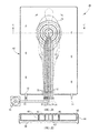
- FIG. 2 is a plan view of a mattress having linear margins and a laterally symmetric fluid flowpath for distributing fluid flowing through the flowpath to a preferred target region of the mattress, constructed according to one or more of the principles disclosed herein;
- FIG. 3 is a cross section taken along section line A--A of FIG. 2 showing a first alternative construction of the mattress, constructed according to one or more of the principles disclosed herein;
- FIG. 4 is a cross section taken along section line A--A of FIG. 2 showing a second alternative construction of the mattress, constructed according to one or more of the principles disclosed herein;
- FIG. 5 is a cross section taken along section line A--A of FIG. 2 showing a third alternative construction of the mattress, constructed according to one or more of the principles disclosed herein;
- FIG. 6 is a cross section taken along section line A--A of FIG. 2 showing a fourth alternative construction of the mattress, constructed according to one or more of the principles disclosed herein;
- FIG. 7 is a plan view of a mattress having contoured margins and a laterally symmetric fluid flowpath for distributing fluid flowing through the flowpath to a preferred target region of the mattress and also showing a pattern of fluid flow through the mattress, constructed according to one or more of the principles disclosed herein;
- FIG. 8 is a cross section taken along section line B--B of FIG. 7 showing a first alternative construction of the mattress, constructed according to one or more of the principles disclosed herein;
- FIGS. 9-11 are plan views similar to that of FIG. 7 showing other variants of contoured margins and laterally symmetric fluid flowpaths, constructed according to one or more of the principles disclosed herein;
- FIG. 12 is a plan view similar to that of FIG. 8 showing another variant of a mattress with contoured margins but with a laterally asymmetric fluid flowpath, constructed according to one or more of the principles disclosed herein;
- FIGS. 13-15 are plan views similar to that of FIG. 7 each showing a longitudinally shortened flowpath, constructed according to one or more of the principles disclosed herein;
- FIG. 16 is a plan view showing a mattress with longitudinally extending, co-flowing fluid flow passages, an array of sensors capable of sensing a parameter useable for determining weight distribution of a person whose weight bears on the mattress, a blower and a controller, constructed according to one or more of the principles disclosed herein;
- FIG. 17 is a plan view showing a mattress with laterally extending, co-flowing fluid flow passages, an array of sensors capable of sensing a parameter useable for determining weight distribution of a person whose weight bears on the mattress, a blower and a controller, constructed according to one or more of the principles disclosed herein;
- FIG. 18 is a plan view showing a mattress with laterally extending, counter-flowing fluid flow passages, an array of sensors capable of sensing a parameter useable for determining weight distribution of a person whose weight bears on the mattress, a blower and a controller, constructed according to one or more of the principles disclosed herein;
- FIGS. 19-20 are plan views showing a mattress with laterally extending co-flowing passages ( FIG. 19 ) and counter-flowing passages ( FIG. 20 ), constructed according to one or more of the principles disclosed herein;
- FIGS. 21-22 are a plan view and a cross sectional view of a mattress having co-flowing nested keyhole passages whose inlets and outlets are at the foot end of the mattress, constructed according to one or more of the principles disclosed herein;
- FIG. 23 is a plan view showing a mattress with counter-flowing, laterally extending passages with a central bulge so that the passages, taken collectively, define a two-sided keyhole configuration, constructed according to one or more of the principles disclosed herein;
- FIGS. 24A-B are cross-sectional views of a mattress showing an insert support layer configured to provide non-uniform resistance to fluid flow through it, constructed according to one or more of the principles disclosed herein.
- a fluid supply supplies fluid through a conduit in the mattress to a targeted zone of the mattress.
- the mattress comprises a base support layer and one or more insert support layers spatially located by the base support layer.
- the one or more insert support layers form a conduit in one embodiment, in another embodiment the base support layer co-operates with the one or more insert support layer to form a conduit for fluid flow.
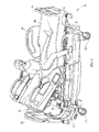
- a person support apparatus or bed 10 comprises a lower frame 12 supported on wheels 14.
- An upper frame 18 is supported by and configured to variably elevate with respect to lower frame 12 by supports 16.
- At least one deck section 20 is supported on the upper frame 18.
- the deck section 20 comprises at least one head support deck section configured to support the upper body of a person, a seat support section configured to support the seat section of a person and a foot support section configured to support the feet of a person.
- the deck section 20 may comprise any number of sections.
- the upper frame 18 may serve the function of the deck section 20 and be comprised of multiple sections.
- the person support apparatus also comprises a head board 22 defining the head end, a foot board 24 defining the foot end and side rails 26 defining the lateral extremities of the person support apparatus 10.
- a mattress 28 is configured to rest upon the deck section 20 of the person support apparatus 10 in this embodiment. In another embodiment, the mattress 28 may be configured to rest upon the upper frame 18.
- a fluid supply 30 is configured to supply fluid into the mattress 28 through an inlet 32. In this embodiment the fluid supply 30 is a blower while in other embodiments the fluid supply 30 may be a compressor or a pump. In the embodiment shown in FIG. 1 the fluid supply is mounted on the lower frame 12, while in another embodiment the fluid supply 30 is mounted on the foot board 24.
- the fluid supply 30 may be mounted on any other portion of the person support apparatus 10 such as the side rails 26 or the deck section 20. In yet another embodiment the fluid supply 30 may be configured to rest on the floor. In this embodiment the fluid supply 30 is dedicated to the system for supplying dedicated fluid flow in a mattress, while in another embodiment the fluid supply 30 is configured to supply fluid for other uses.
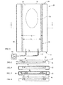
- FIG. 2 shows a top view of one embodiment of a system to supply dedicated fluid flow in a mattress 28.
- the mattress 28 comprises a base support layer 38 (shown in FIG. 3-6 ) and an insert support layer 40.
- Fluid supply 30 provides a supply of fluid through the inlet 32 into the mattress 28.
- the mattress 28 is configured to allow for fluid flowing into the mattress 28 to leave the mattress through outlet 34. Fluid flowing into the mattress is configured to be directed to a target region 36.
- the mattress extends in longitudinal and lateral directions and includes conduit 84 defining a fluid flowpath for channeling a stream of air through the mattress from an inlet 32 to an outlet 34.
- conduit 84 defining a fluid flowpath for channeling a stream of air through the mattress from an inlet 32 to an outlet 34.
- mattress inlet 32 is a pair of inlet ports at the foot end 48 of the mattress and outlet 64 is a vent opening at the head end 50 of the mattress.
- the mattress of FIG. 2 is configured to distribute air flowing through the flowpath to a preferred target region 36 of the mattress, specifically a region corresponding approximately to the torso of a supine person substantially laterally centered on the mattress, although other target regions can be defined, if desired.
- the mattress includes a base support layer 38 which has a cutout in this embodiment to receive and locate at least one insert support layer 40.
- the insert support layer 40 and the base support layer 38 have a cross-section to channel the air flow through the cross-section.
- the base support layer and the insert support layer are made of closed cell foam.
- the base support layer and / or the insert support layer are constructed of inflated bladders.
- both the base support layer and / or the insert support layers may be made of any combination of foam, polymeric material and / or inflated bladders.
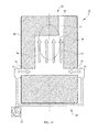
- FIGS. 3-6 depict cross-sections of some contemplated embodiments of a system to supply dedicated fluid flow in a mattress 28 along section A-A in FIG. 2 , although the cross-sections shown in FIGS. 3-6 may be used with configurations shown in FIGS. 7 , 9-23 in other embodiments.
- FIG. 3 shows one contemplated embodiment wherein the base support layer 38 comprises a cutout which spatially locates an insert support layer 40. As shown in FIGS. 3 - 6 , the base support layer 38 and the insert support layer 40 co-operate to form a conduit 84 for fluid flow. As shown in FIGS. 3-6 a boundary sheet 42 covers the conduit 84 formed by the base support layer 38 and the insert support layer 40.
- the boundary sheet 42 is connected to the base support layer 38 using hook and loop connection in the embodiment shown in FIG. 3 .
- any form of coupling may be used to secure the boundary sheet 42, including but not limited to buttons, zippered connections and snap fit connections.
- the embodiment shown in FIG.4 comprises an elasticized perimeter boundary sheet 42 which allows it to be coupled with respect to the base support layer 38.
- FIG. 5 shows one embodiment of the system to supply dedicated fluid flow in a mattress 28 wherein a second support insert layer 46 is used in conjunction with the insert support layer 40 and the base support layer 38 to form the conduit 84 for fluid flow. In another embodiment, any number of insert support layers may be used to form the conduit 84 for fluid flow.
- FIG. 6 shows one embodiment of a system to supply dedicated fluid flow in a mattress 28 wherein the boundary sheet 42 is coupled to the insert support layer 40 instead of the base support layer 38.
- the boundary sheet 42 is coupled to both the insert support layer 40 and the base support layer 38.
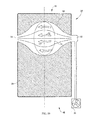
- FIGS. 7-8 show another embodiment of a mattress 28 configured to distribute air flowing through the flowpath 52 to target region 50 of the mattress 28.
- the mattress 28 includes left and right arcuate margins. The margins converge toward each other with increasing distance from the head and foot ends 50, 48 of the mattress to define a throat coincident with section lines B-B. As a result of the flowpath shape arising from the curved borders, airstream is more concentrated under the target region 36.
- a blower 30 supplies air through the inlet 32 to conduit 84 of the mattress.
- FIG. 8 depicts a cross-section of one contemplated embodiment of a system to supply dedicated fluid flow in a mattress 28 along section B-B in FIG. 7 , although the cross-sections shown in FIGS. 8 may be used with configurations shown in FIGS. 2 , 9-23 in other embodiments.
- the base support layer 38 and / or the insert support layer 40 may be shaped or placed to provide variable cross section from the foot end 38 to the head end 50.
- FIG. 9 shows an embodiment in which the margins diverge away from each other with increasing distance from the head and foot ends 50, 48 of the mattress.
- the resulting flowpath 52 allows airstream to diffuse laterally as it moves from inlet 62 toward targeted region 36.
- a manifold 54 distributes air into the inlet 32 in this embodiment.
- FIG. 10 shows an embodiment having dual inlets 32 and dual intake manifold 54 for channeling air to a working region 86 of the flowpath 52, and a single outlet 34 and a single conduit 84 for exhausting the airstream from the working region 86.
- the working region 86 corresponds approximately to the target region 36 which may correspond to the torso of a supine person substantially laterally centered on the mattress 28.
- FIGS. 10-23 show embodiments wherein the cross-section is that of FIG.8 , in other embodiments any cross-section may be used.
- FIGS. 3-6 show cross-sectional arrangement of elements for FIGS. 10-23 in other embodiments.
- FIG. 11 shows an embodiment similar to that of FIG. 10 but having dual outlets 34 and a pair of conduits 84 for channeling airstream away from working region 86 of the flowpath 52.
- the working region 86 corresponds approximately to the target region 36 which may correspond to the torso of a supine person substantially laterally centered on the mattress.
- FIG. 12 shows an embodiment having a single inlet 32 and a single conduit 84 for channeling airstream to working region 86 and a single outlet 34 and a single conduit 84 for exhausting the airstream from the working region 86.
- the working region 86 corresponds approximately to the target region 36 which may correspond to the torso of a supine person substantially laterally centered on the mattress.
- the flowpath of FIG. 12 is asymmetric with respect to the centerplane.
- FIG. 13 shows an embodiment similar to that of FIG. 8 but with dual inlets 32 and a longitudinally shortened flowpath 52.
- FIG. 14 shows an embodiment similar to that of FIG. 13 but with a working region 86 having an arched planform and a conduit 84 extending obliquely from the target region 36.
- FIG. 15 shows an embodiment similar to that of FIG. 14 but with a working region 86 having a rectangular planform.
- FIGS. 16 shows a mattress in which flowpath 52 is divided into a set of five longitudinally extending, laterally distributed fluid passages.
- the mattress also includes an array of sensors 56 capable of sensing a parameter useable for determining weight distribution of a person whose weight bears on the mattress.
- One example is an array of pressure sensors.
- a blower 30 is in fluid communication with mattress flowpath 52 by way of a plumbing network comprising a mainifold 54 and a set of branch pipes each outfitted with a valve 66 and each connected to the foot end of one passage.
- the passages are coflowing passages, i.e. airflow in all the passages is in the same direction, from the foot end toward the head end.
- a controller 58 is in communication with the sensors 56, the valves 66 and the blower 30 as indicated by communication pathways 60, 62 and 64 respectively.
- communication pathways 60, 62, 64 represent a tangible physical connection in this embodiment, other avenues of communication, such as wireless communication, can also be employed in other embodiments.
- the controller receives a signal or signals representing a value or values of the sensed parameter or parameters and controls the valves to cause air to be metered to the passages in response to the signal or signals such that a larger proportion of fluid supplied to the flowpath is directed to the target region and a smaller proportion bypasses the target region.
- the controller is programmed to meter only 10% of the air to each of passages 68, 76 and to distribute the remaining 80% equally or unequally among channels 70, 72, 74.
- Other distributions could be commanded depending on changes in the location of the target region which result from changes in the position of the occupant as detected by the sensors.
- the controller of FIG. 16 is an on-board controller in that it is mounted on the bed itself. Alternatively the controller could be an off-board controller. Off-board controllers include controllers that are components of facility communication and data processing networks.
- FIGS. 17 and 18 show seven channels labels 68, 70, 72, 74, 76, 78 and 80 with co-flowing and counter flowing flowpaths repectively.
- FIG. 18 shows a mattress similar to that of FIG. 16-17 but with counterflowing passages, that is, air flows right to left in passages 70, 74, 78 and left to right in the other passages.
- FIG. 18 also illustrates the use of appropriate flow restriction such as a nozzle in one embodiment, indicated by size of the fluid supply line to the inlet 32, to regulate airflow distribution among the passages.
- FIGS. 16 - 18 illustrate the use of sensors 56 so that the mattress, with the assistance of controller 58 and valves 66, can adapt to changes in the position of the patient.
- the sensors can be dispensed with, and airflow can be distributed nonuniformly among the passages with appropriately designed, nonadjustable flow restrictions governing airflow through each branch pipe.
- the flow restrictions may be manually adjustable rather than automatically adjustable. Such an arrangement might be useful to adapt the distribution of airflow to occupant specific target regions, in one prophetic example a smaller target region for a patient of smaller size and a larger target region for a patient of larger size.
- FIG. 19 shows a mattress with a flowpath that increases in longitudinal dimension with increasing lateral distance from the inlets to the centerplane.
- the passages are coflowing passages.
- the illustrated mattress does not use sensors, valves or flow restrictions to govern the distribution of airflow through the passages, however such use is within the scope of this disclosure.
- FIG. 20 shows a counterflowing variant of the system of FIG. 19 .
- FIG. 21 shows a mattress in which the flowpath 52 has a keyhole shape as seen in a plan view.
- the flowpath has three inner nested, coflowing fluid passages 52.
- the illustrated mattress also comprises a passage outboard of the inner nested keyhole shaped flowpath 52.
- a nonflowing outboard region could be used in lieu of the outboard flowpath.
- FIG. 22 shows a cross-sectional view of another embodiment with two inner nested flow paths surrounded by the outboard flow path.
- FIG. 23 shows a mattress with counterflowing, laterally extending passages whose inlets 32 and outlets 34 are at the side of the bed rather than at a longitudinal end of the mattress 28 having a bulging working region 86 so that the passages, taken collectively, define a two-sided keyhole configuration.
- FIGS. 24A & B shows a cross-section of a mattress 28 comprising a base support layer 38 and an insert support layer 40.
- the base support layer 38 is constructed of closed cell foam or bladders in this embodiment.
- the insert support layer 40 comprises passages spaced apart from each other to allow fluid flow through it.
- the insert support layer 40 is configured to provide non-uniform resistance to fluid flow through it.
- the insert support layer 40 comprise variably sized passages to allow greater fluid flow towards the center of the cross-section as relative to the peripheral regions of the cross-section.
- the insert support layer 40 may comprises a non-uniform distribution of spacing between the passages along the cross-section of the mattress 28.
- multiple insert support layers each with their individual distribution of passages may be used to achieve variable fluid flow resistance.
- the distribution of identically sized passages may be varied along the cross-section and / or length of the mattress 28 to achieve variable fluid flow resistance.
Landscapes
- Health & Medical Sciences (AREA)
- Veterinary Medicine (AREA)
- Life Sciences & Earth Sciences (AREA)
- Animal Behavior & Ethology (AREA)
- General Health & Medical Sciences (AREA)
- Public Health (AREA)
- Nursing (AREA)
- Engineering & Computer Science (AREA)
- Biomedical Technology (AREA)
- Heart & Thoracic Surgery (AREA)
- Vascular Medicine (AREA)
- Invalid Beds And Related Equipment (AREA)
- Mattresses And Other Support Structures For Chairs And Beds (AREA)
Applications Claiming Priority (1)
| Application Number | Priority Date | Filing Date | Title |
|---|---|---|---|
| US201261683300P | 2012-08-15 | 2012-08-15 |
Publications (1)
| Publication Number | Publication Date |
|---|---|
| EP2698080A1 true EP2698080A1 (de) | 2014-02-19 |
Family
ID=48979564
Family Applications (1)
| Application Number | Title | Priority Date | Filing Date |
|---|---|---|---|
| EP13179629.4A Withdrawn EP2698080A1 (de) | 2012-08-15 | 2013-08-07 | Systeme zur Kontrolle einer Flüssigkeitsströmung in einer Matratze |
Country Status (2)
| Country | Link |
|---|---|
| US (2) | US9572433B2 (de) |
| EP (1) | EP2698080A1 (de) |
Cited By (1)
| Publication number | Priority date | Publication date | Assignee | Title |
|---|---|---|---|---|
| EP3262989A1 (de) * | 2016-06-27 | 2018-01-03 | Nitetronic Holding Limited | Luftstromsteuerung für kopfstütze |
Families Citing this family (27)
| Publication number | Priority date | Publication date | Assignee | Title |
|---|---|---|---|---|
| WO2009036077A1 (en) | 2007-09-10 | 2009-03-19 | Amerigon, Inc. | Operational control schemes for ventilated seat or bed assemblies |
| US9125497B2 (en) * | 2007-10-15 | 2015-09-08 | Gentherm Incorporated | Climate controlled bed assembly with intermediate layer |
| CN104523071A (zh) | 2008-07-18 | 2015-04-22 | 金瑟姆股份公司 | 气候受控床组件 |
| US8332975B2 (en) | 2009-08-31 | 2012-12-18 | Gentherm Incorporated | Climate-controlled topper member for medical beds |
| BR112013029688A2 (pt) * | 2011-05-23 | 2017-01-17 | Koninkl Philips Nv | sistema e método de ajuste do microclima de ambientes de cama, uso de um sistema e uso de aquecimento por meio de fios de resistência elétrica em combinação com o fluxo de ar |
| US9131780B2 (en) | 2012-02-14 | 2015-09-15 | Hill-Rom Services, Inc. | Topper with preferential fluid flow distribution |
| US20130212808A1 (en) | 2012-02-21 | 2013-08-22 | Charles A. Lachenbruch | Topper with Targeted Fluid Flow Distribution |
| US9572433B2 (en) | 2012-08-15 | 2017-02-21 | Hill-Rom Services, Inc. | Systems and methods for directing fluid flow in a mattress |
| US10842288B2 (en) * | 2017-01-31 | 2020-11-24 | Hill-Rom Services, Inc. | Person support systems with cooling features |
| US10856668B2 (en) | 2017-04-10 | 2020-12-08 | Hill-Rom Services, Inc. | Mattress overlay control system with rotary valves and graphical user interface for percussion and vibration, turn assist and microclimate management |
| US11173085B2 (en) | 2017-12-28 | 2021-11-16 | Stryker Corporation | Mattress cover for a mattress providing rotation therapy to a patient |
| US11246775B2 (en) | 2017-12-28 | 2022-02-15 | Stryker Corporation | Patient turning device for a patient support apparatus |
| USD888964S1 (en) | 2018-09-28 | 2020-06-30 | Stryker Corporation | Crib assembly for a patient support |
| USD877915S1 (en) | 2018-09-28 | 2020-03-10 | Stryker Corporation | Crib assembly |
| USD888963S1 (en) | 2018-09-28 | 2020-06-30 | Stryker Corporation | Cover assembly for a patient support |
| USD888962S1 (en) | 2018-09-28 | 2020-06-30 | Stryker Corporation | Cover assembly for a patient support |
| USD977109S1 (en) | 2018-09-28 | 2023-01-31 | Stryker Corporation | Crib assembly for a patient support |
| USD879966S1 (en) | 2018-09-28 | 2020-03-31 | Stryker Corporation | Crib assembly |
| USD901940S1 (en) | 2018-09-28 | 2020-11-17 | Stryker Corporation | Patient support |
| USD894957S1 (en) | 2018-10-31 | 2020-09-01 | Stryker Corporation | Display screen or portion thereof with graphical user interface |
| USD890914S1 (en) | 2018-10-31 | 2020-07-21 | Stryker Corporation | Pump |
| USD893543S1 (en) | 2018-10-31 | 2020-08-18 | Stryker Corporation | Display screen with graphical user interface |
| USD892159S1 (en) | 2018-10-31 | 2020-08-04 | Stryker Corporation | Display screen with animated graphical user interface |
| USD894226S1 (en) | 2018-10-31 | 2020-08-25 | Stryker Corporation | Display screen or portion thereof with graphical user interface |
| USD894956S1 (en) | 2018-10-31 | 2020-09-01 | Stryker Corporation | Display screen or portion thereof with graphical user interface |
| USD894223S1 (en) | 2018-10-31 | 2020-08-25 | Stryker Corporation | Display screen with animated graphical user interface |
| US20230000269A1 (en) * | 2021-07-04 | 2023-01-05 | James A. Waring | Pillow with proximal air flow delivery manifold |
Citations (6)
| Publication number | Priority date | Publication date | Assignee | Title |
|---|---|---|---|---|
| DE2339645A1 (de) * | 1973-08-04 | 1975-02-13 | Richard Stelzer | Unterlage fuer den menschlichen koerper |
| US5226188A (en) * | 1992-06-26 | 1993-07-13 | Liou Yaw Tyng | Ventilated foam cushion |
| US20070261548A1 (en) * | 2006-05-11 | 2007-11-15 | Kci Licensing, Inc., Legal Department, Intellectual Property | Multi-layered support system |
| US20080263776A1 (en) * | 2007-04-30 | 2008-10-30 | Span-America Medical Systems, Inc. | Low air loss moisture control mattress overlay |
| WO2011026040A1 (en) * | 2009-08-31 | 2011-03-03 | Amerigon Incorporated | Climate-controlled topper member for medical beds |
| US20120131748A1 (en) * | 2006-10-13 | 2012-05-31 | Amerigon Incorporated | Heated and cooled bed assembly |
Family Cites Families (20)
| Publication number | Priority date | Publication date | Assignee | Title |
|---|---|---|---|---|
| US4660388A (en) | 1984-05-24 | 1987-04-28 | Greene Jr George J | Cooling cover |
| ATE74261T1 (de) | 1987-10-05 | 1992-04-15 | Augustine Medical Inc | Waermedecke. |
| US6269505B1 (en) | 1999-04-20 | 2001-08-07 | M.P.L. Ltd. | Inflatable cushioning device with manifold system |
| US6493889B2 (en) | 2001-01-29 | 2002-12-17 | Project Cool Air, Inc. | Cooling cover apparatus |
| US7036163B2 (en) | 2002-02-06 | 2006-05-02 | Halo Innovations, Inc. | Furniture cover sheet |
| US20040237206A1 (en) | 2003-05-29 | 2004-12-02 | Kara Webster | Dual air ventilation pad |
| US8108957B2 (en) | 2007-05-31 | 2012-02-07 | Hill-Rom Services, Inc. | Pulmonary mattress |
| US9125497B2 (en) | 2007-10-15 | 2015-09-08 | Gentherm Incorporated | Climate controlled bed assembly with intermediate layer |
| US8856993B2 (en) | 2008-04-15 | 2014-10-14 | Hill-Rom Services, Inc. | Temperature and moisture regulating topper for non-powered person-support surfaces |
| CN104523071A (zh) | 2008-07-18 | 2015-04-22 | 金瑟姆股份公司 | 气候受控床组件 |
| US8327477B2 (en) | 2009-06-29 | 2012-12-11 | Hill-Rom Services, Inc. | Localized microclimate management |
| US8531307B2 (en) | 2009-09-18 | 2013-09-10 | Hill-Rom Services, Inc. | Patient support surface index control |
| US8365330B2 (en) | 2010-02-12 | 2013-02-05 | Hill-Rom Services, Inc. | Method and apparatus for relieving shear induced by and occupant support |
| US10045630B2 (en) | 2010-05-28 | 2018-08-14 | Marlow Industries, Inc. | System and method for thermoelectric personal comfort controlled bedding |
| US20130212808A1 (en) * | 2012-02-21 | 2013-08-22 | Charles A. Lachenbruch | Topper with Targeted Fluid Flow Distribution |
| US9131780B2 (en) * | 2012-02-14 | 2015-09-15 | Hill-Rom Services, Inc. | Topper with preferential fluid flow distribution |
| US9009892B2 (en) | 2012-05-10 | 2015-04-21 | Hill-Rom Services, Inc. | Occupant support and topper assembly with liquid removal and microclimate control capabilities |
| US9572433B2 (en) | 2012-08-15 | 2017-02-21 | Hill-Rom Services, Inc. | Systems and methods for directing fluid flow in a mattress |
| US8943627B2 (en) | 2012-10-19 | 2015-02-03 | Jeffrey W. Wilkinson | Cushioning device and method of cushioning a body |
| US9907718B2 (en) | 2013-01-11 | 2018-03-06 | Hill-Rom Services, Inc. | Mattress topper, occupant support assembly and occupant support system with thermosensitive vapor transfer characteristics |
-
2013
- 2013-08-07 US US13/960,860 patent/US9572433B2/en active Active
- 2013-08-07 EP EP13179629.4A patent/EP2698080A1/de not_active Withdrawn
-
2017
- 2017-02-09 US US15/428,570 patent/US10555854B2/en active Active
Patent Citations (6)
| Publication number | Priority date | Publication date | Assignee | Title |
|---|---|---|---|---|
| DE2339645A1 (de) * | 1973-08-04 | 1975-02-13 | Richard Stelzer | Unterlage fuer den menschlichen koerper |
| US5226188A (en) * | 1992-06-26 | 1993-07-13 | Liou Yaw Tyng | Ventilated foam cushion |
| US20070261548A1 (en) * | 2006-05-11 | 2007-11-15 | Kci Licensing, Inc., Legal Department, Intellectual Property | Multi-layered support system |
| US20120131748A1 (en) * | 2006-10-13 | 2012-05-31 | Amerigon Incorporated | Heated and cooled bed assembly |
| US20080263776A1 (en) * | 2007-04-30 | 2008-10-30 | Span-America Medical Systems, Inc. | Low air loss moisture control mattress overlay |
| WO2011026040A1 (en) * | 2009-08-31 | 2011-03-03 | Amerigon Incorporated | Climate-controlled topper member for medical beds |
Cited By (2)
| Publication number | Priority date | Publication date | Assignee | Title |
|---|---|---|---|---|
| EP3262989A1 (de) * | 2016-06-27 | 2018-01-03 | Nitetronic Holding Limited | Luftstromsteuerung für kopfstütze |
| WO2018001969A1 (en) * | 2016-06-27 | 2018-01-04 | Nitetronic Holding Limited | Airflow control for head support |
Also Published As
| Publication number | Publication date |
|---|---|
| US20170151113A1 (en) | 2017-06-01 |
| US20140047646A1 (en) | 2014-02-20 |
| US10555854B2 (en) | 2020-02-11 |
| US9572433B2 (en) | 2017-02-21 |
Similar Documents
| Publication | Publication Date | Title |
|---|---|---|
| US10555854B2 (en) | Systems and methods for directing fluid flow in a mattress | |
| US12082701B2 (en) | Topper with targeted fluid flow distribution | |
| US11903888B2 (en) | Conditioner mat system for use with a bed assembly | |
| EP3094213B1 (de) | Raumtemperaturbett mit einem wärmerückgewinnungssystem | |
| US20180042762A1 (en) | Thermal system | |
| RU2665982C2 (ru) | Кресло транспортного средства с системой климат-контроля | |
| US20080148481A1 (en) | Air conditioned bed | |
| CN106394359A (zh) | 用于座椅的空调装置 | |
| US10130538B2 (en) | Pneumatic mattress | |
| EP2628413B1 (de) | Auflage und Bett mit gezielter Flüssigkeitsströmungsverteilung und bevorzugter Flüssigkeitsströmungsverteilung | |
| EP3262989A1 (de) | Luftstromsteuerung für kopfstütze | |
| EP2465480B1 (de) | Aufblasbare Matratze | |
| US11554040B2 (en) | Thermal system with thermal pad filters | |
| WO2026036129A1 (en) | Inflatable zone-specific cushion and method for using the same | |
| KR20100039789A (ko) | 소형보일러 온수메트 개폐구(開閉口)장치 | |
| HK1225241B (en) | Ambient bed having a heat reclaim system | |
| KR20150001762U (ko) | 침낭 겸용 온수매트 |
Legal Events
| Date | Code | Title | Description |
|---|---|---|---|
| AK | Designated contracting states |
Kind code of ref document: A1 Designated state(s): AL AT BE BG CH CY CZ DE DK EE ES FI FR GB GR HR HU IE IS IT LI LT LU LV MC MK MT NL NO PL PT RO RS SE SI SK SM TR |
|
| AX | Request for extension of the european patent |
Extension state: BA ME |
|
| PUAI | Public reference made under article 153(3) epc to a published international application that has entered the european phase |
Free format text: ORIGINAL CODE: 0009012 |
|
| 17P | Request for examination filed |
Effective date: 20140814 |
|
| RBV | Designated contracting states (corrected) |
Designated state(s): AL AT BE BG CH CY CZ DE DK EE ES FI FR GB GR HR HU IE IS IT LI LT LU LV MC MK MT NL NO PL PT RO RS SE SI SK SM TR |
|
| 17Q | First examination report despatched |
Effective date: 20160923 |
|
| STAA | Information on the status of an ep patent application or granted ep patent |
Free format text: STATUS: EXAMINATION IS IN PROGRESS |
|
| RIN1 | Information on inventor provided before grant (corrected) |
Inventor name: O'KEEFE, CHRISTOPHER R. Inventor name: LACHENBRUCH, CHARLES A. Inventor name: WILLIAMSON, RACHEL Inventor name: RECEVEUR, TIMOTHY J. |
|
| STAA | Information on the status of an ep patent application or granted ep patent |
Free format text: STATUS: THE APPLICATION HAS BEEN WITHDRAWN |
|
| 18W | Application withdrawn |
Effective date: 20220715 |