EP2698123B1 - Ablagesystem und Verfahren zum Herstellen eines benutzerdefinierten Informationsblattes - Google Patents
Ablagesystem und Verfahren zum Herstellen eines benutzerdefinierten Informationsblattes Download PDFInfo
- Publication number
- EP2698123B1 EP2698123B1 EP12180535.2A EP12180535A EP2698123B1 EP 2698123 B1 EP2698123 B1 EP 2698123B1 EP 12180535 A EP12180535 A EP 12180535A EP 2698123 B1 EP2698123 B1 EP 2698123B1
- Authority
- EP
- European Patent Office
- Prior art keywords
- sheet
- tray
- holes
- holding
- base
- Prior art date
- Legal status (The legal status is an assumption and is not a legal conclusion. Google has not performed a legal analysis and makes no representation as to the accuracy of the status listed.)
- Active
Links
Images



Classifications
-
- A—HUMAN NECESSITIES
- A61—MEDICAL OR VETERINARY SCIENCE; HYGIENE
- A61C—DENTISTRY; APPARATUS OR METHODS FOR ORAL OR DENTAL HYGIENE
- A61C3/00—Dental tools or instruments
- A61C3/04—Supports for holding tooth drills in order of use
-
- A—HUMAN NECESSITIES
- A61—MEDICAL OR VETERINARY SCIENCE; HYGIENE
- A61F—FILTERS IMPLANTABLE INTO BLOOD VESSELS; PROSTHESES; DEVICES PROVIDING PATENCY TO, OR PREVENTING COLLAPSING OF, TUBULAR STRUCTURES OF THE BODY, e.g. STENTS; ORTHOPAEDIC, NURSING OR CONTRACEPTIVE DEVICES; FOMENTATION; TREATMENT OR PROTECTION OF EYES OR EARS; BANDAGES, DRESSINGS OR ABSORBENT PADS; FIRST-AID KITS
- A61F2/00—Filters implantable into blood vessels; Prostheses, i.e. artificial substitutes or replacements for parts of the body; Appliances for connecting them with the body; Devices providing patency to, or preventing collapsing of, tubular structures of the body, e.g. stents
- A61F2/02—Prostheses implantable into the body
- A61F2/30—Joints
- A61F2/44—Joints for the spine, e.g. vertebrae, spinal discs
-
- A—HUMAN NECESSITIES
- A61—MEDICAL OR VETERINARY SCIENCE; HYGIENE
- A61C—DENTISTRY; APPARATUS OR METHODS FOR ORAL OR DENTAL HYGIENE
- A61C8/00—Means to be fixed to the jaw-bone for consolidating natural teeth or for fixing dental prostheses thereon; Dental implants; Implanting tools
- A61C8/0087—Means for sterile storage or manipulation of dental implants
-
- A—HUMAN NECESSITIES
- A61—MEDICAL OR VETERINARY SCIENCE; HYGIENE
- A61C—DENTISTRY; APPARATUS OR METHODS FOR ORAL OR DENTAL HYGIENE
- A61C19/00—Dental auxiliary appliances
- A61C19/02—Protective casings, e.g. boxes for instruments; Bags
-
- Y—GENERAL TAGGING OF NEW TECHNOLOGICAL DEVELOPMENTS; GENERAL TAGGING OF CROSS-SECTIONAL TECHNOLOGIES SPANNING OVER SEVERAL SECTIONS OF THE IPC; TECHNICAL SUBJECTS COVERED BY FORMER USPC CROSS-REFERENCE ART COLLECTIONS [XRACs] AND DIGESTS
- Y10—TECHNICAL SUBJECTS COVERED BY FORMER USPC
- Y10T—TECHNICAL SUBJECTS COVERED BY FORMER US CLASSIFICATION
- Y10T29/00—Metal working
- Y10T29/49—Method of mechanical manufacture
- Y10T29/49826—Assembling or joining
Definitions
- the present invention relates to a tray system comprising a tray with a base having holding arrangements for holding implant components, instruments and/or instrument holders.
- the present invention further relates to a method of preparing a customized information sheet for a tray with a base having holding arrangements in a specific pattern for holding implant components, instruments and/or instrument holders.
- the instruments are often arranged to a tray in a specific position in order to help the surgeon to find the right instrument fast.
- the tray may be provided with instrument holders, for example a hole with a grommet arranged therein.
- an information text or an identifying colour may be printed on the tray in order to make it easier to find the correct instrument for a certain operation.
- the instrument providers gives the instruments to be used in a specific surgical operation a certain colour.
- the text and the colour on the tray may correspond to the colour on the instrument.
- the surgical tray is prepared with, for example, different drills and the implants to be used.
- a custom drilling and installation protocol may state what implants, drills and implants holders to use in each specific osteotomy.
- the correct drills and implants are then arranged to the tray according to the protocol and in the right holders according to the text on the tray. Hence, for each specific situation, i.e. implant type, size etc., the tray is loaded differently.
- the text and colour on the tray may not correspond to the colour or the order of the instruments to be used and is then more confusing than helping.
- US 5,525,314 A discloses a surgical tool container system which includes an outer case having a separable base and lid portions with a tool-holding tray removably inserted within the base portion of the case.
- the tray is provided with a plurality of holes formed therethrough.
- US 2012/0094249 A1 discloses a tray assembly comprising a tray, a removable plate and a lid.
- the plate is provided with biasing means, whereby instruments are friction held.
- the object of the present invention is to provide a tray system that overcomes the above issues.
- the invention is based on the insight that by allowing the information associated with holders in a tray to be separated from those holders, a more flexible tray system may be provided.
- the inventors have also realized that by providing the option of concealing some of the holders and reducing the information, the user may be faced with only such information which he/she needs for a particular surgery.
- a tray system comprising a tray with a base having holding arrangements for holding implant components, instruments and/or instrument holders, at least a first and a second information sheet which both are adapted to be independently removably arranged on said base of said tray, wherein said first sheet is replaceable by said second sheet and vice versa, said first sheet comprises a first set of holes having a first distribution and said second sheet comprises a second set of holes having a second distribution, which is different compared to the first distribution, wherein when said first sheet is arranged on said base of said tray each one of said first set of holes in said first sheets is located in register with a respective one of said holding arrangements so that an implant component, instrument or instrument holder is arrangable into one of said holding arrangements through a respective one of said first set of holes and when said second sheet is arranged on said base of said tray each one of said second set of holes in said second sheet is located in register with a respective one of said holding arrangements so that an implant component, instrument or instrument holder is
- the user can choose the one suitable for a specific situation.
- the user can arrange a separate sheet on the tray which is suitable for a specific use which makes it easier for the user to arrange the right component on the tray and then find it again during surgery.
- the second sheet may be used having a hole distribution which is more appropriate for that specific situation.
- the user may design his own sheet. This way the user can get a tray system which is adapted to his or hers specific needs.
- the holes in the first information sheet may be in register with some holding arrangements in said base, while when the second information sheet is arranged on the base of the tray the holes in the second information sheet may be in register with completely different holding arrangements in said base.
- some of the holes of the first and the second sheets may be in register with the same holding arrangements, and the second sheet may for example have additional holes which are in register with other holding arrangements.
- said at least one of said first sheet and said second sheet comprises a coloured area and/or information text next to at least one of the holes.
- Information text and coloured areas may help the user to organise the objects to be arranged in the holding arrangements. It may also help the user to find the right object and/or the objects which belong to each other.
- a special drill or special drills and/or tools may have to be used and they can then be identified with colours and text, i.e. they may be colour coded.
- a dental implant having a diameter of 3.5 mm all relevant drills and tools may be marked in a specific colour, for example in red, and they may then be arranged in an area on the sheet which has a red marking.
- Another dental implant for example having a diameter of 4.0 mm, may be associated with a different colour, for example yellow.
- Text information and/or figures may help the user further to organise the objects in the right place and help the user to find the correct objects.
- the information text and/or coloured area i.e. the information markings, may be printed or attached to the sheet by a stick-on-label or it may be in-mould decoration or in-mould labelling in the sheet.
- said at least one of said holes in said first set of holes and/or said second set of holes is larger in cross-section than the holding arrangement it is in register with.
- said first sheet and/or said second sheet are arrangable to said tray by a snap locking arrangement.
- Snap locking arrangements are easy fasteners, i.e. they are often easy to arrange and may be designed to be easy to remove.
- a snap locking arrangement may be a snap catch arranged on the sheet and which snaps into an opening in the tray.
- Another alternative may be a snap catch on the tray which snaps into a hole in the sheet or alternative over the edge of the sheet.
- the sheets may only be loosely placed on the tray.
- At least one of said holding arrangements is an aperture in said base.
- An aperture in the base is a cost effective way to make a holding arrangement.
- the aperture may be a through hole.
- the through hole may be fitted for example with a grommet which may hold the objects.
- the aperture has preferably a round shape.
- said holding arrangement comprises flexible protrusions arranged circumferentially around a centre axis of the holding arrangement. They are preferably evenly distributed around the holding arrangement.
- said flexible protrusions are protruding in the opposite direction to the side of the base on which the sheets are arrangeable and the through hole has a cross-sectional area at the side of the base on which the sheets are arrangeable which is larger than a cross-sectional area of the through hole at the end of the flexible protrusion.
- Flexible protrusions together with a larger open cross-sectional area at the top than at the end of the flexible protrusions have the advantage that the flexible protrusions may bend away when a tool or an implant is arranged in the holding arrangement. This way differently sized tools and implants can be fitted within the holding arrangement.
- the change of area may be accomplished by the flexible protrusions slightly protruding downwards and towards the centre axis of the holding arrangement. According to at least one exemplary embodiment they may be slanting towards the centre axis of the holding arrangement. The flexible protrusions may then be also slanted in the direction towards the centre axis and/or they may be parallel with the centre axis. All flexible protrusions may be the same or they may be differently designed. According to at least one exemplary embodiment the holding arrangement comprises three flexible protrusions. There may however be more or less.
- said first and/or second sheets are made of plastic or paper.
- the sheets may be made in a material which can be sterilized and/or disinfected for example plastic.
- the sheet may be a disposable sheet which can be thrown away.
- the sheet is relatively rigid.
- the thickness of the sheet is preferably not thicker than the tools and/or parts which shall be held in the holding arrangement, i.e. the tool or the part should protrude above the sheet so that the user easily can remove the tools/parts.
- said first or said second sheet is arrangable to said base adjacent to a third sheet.
- This can be an alternative to one large sheet. For example if a clinic would like to build its own sheet out of smaller module sheets.
- the object of the present invention is accomplished by a method of preparing a customized information sheet for a tray system according to the first aspect of the invention, the method comprises the steps of gathering information regarding positions of a subset of holding arrangements to be used, producing a sheet with holes having corresponding positions of the subset of holding arrangements such that when said sheet is arranged on said base of said tray each one of said holes in said sheet is located in register with a respective one of said holding arrangements to be used so that an implant component, instrument or instrument holder is arrangable into one of said holding arrangements through a respective one of said holes.
- the user may tell the producer of the sheets which holding arrangements he wants to use. This may for example be done over the Internet.
- the producers of the sheets can then make a sheet with holes in the right place.
- the user then gets a customized sheet.
- Another advantage of customized sheets is that they may be designed to support a different drilling protocol, procedure, treatment option or implant system, for example from another producer.
- said method further comprises the steps of gathering colour information and/or text information to be arranged on said sheet next to at least one of the holes and arranging said colour information and/or said text information on said sheet.
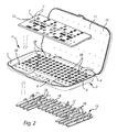
- Fig. 1 and Fig. 2 show a tray system 1 which comprises a rectangular shaped tray 2 which has a base 4 and low side walls 5 all around.
- the tray is not limited to low side walls. There might not be a side wall at all or it may be higher.
- the tray is also not limited to be a rectangular shaped tray. It may for example be round.
- On the base 4 is an information sheet 3 with information markings 12 (information markings not shown in Fig. 1 ) arranged.
- the tray 2 is suitably made of plastic, however, it may be made of any kind of suitable material.
- the tray is made of a material which can be disinfected and/or sterilized.
- the tray 2 is pivotally connected to a lid 10 which in a closed condition covers the base 4.
- the lid 10 is a separate lid.
- the lid 10 has openings 11 which permit steam or other sterilant to enter into and out of the tray system 1 when the lid 10 covers the tray 2, for example when the tray system 1 is being sterilized.
- the sheet 3 may be a plastic sheet or a paper sheet or a sheet out of metal.
- the sheet is relatively rigid.
- the thickness of the sheet is suitably not thicker than the tools and/or parts which shall be held in the tray, i.e. the tool or the part should protrude over the sheet 3 so that the user easily can remove the tools/parts. If the sheet 3 shall withstand to be disinfected and/or sterilized it is preferably made in a material suitable for this.
- information markings 12 are printed. As an alternative the information markings may be attached to the sheet by a stick on label 13 as shown in Fig. 3 or in-mould decoration or in-mould labelling.
- the base 4 of the tray 2 comprises apertures 6, see Fig. 2 , which are arranged in rows. These apertures 6 are holdings arrangements 6 for instruments, implants etc. As exemplified the holding arrangements 6 themselves are designed to hold an instrument, an instrument holder or a part to be implanted. The design will be discussed together in regard to the Figures 4-8 . As an alternative a holding arrangement 6 may be a round through hole into which for example a known grommet can be inserted to hold the instrument.
- the sheet 3 comprises a first set of holes 7' integrated in the sheet.
- the holes 7' are distributed over the sheet in a first distribution, i.e. a first pattern.
- the holes 7' on the sheet 3 are so arranged that when the sheet 3 is arranged on the base 4, each hole 7' on the sheet 3 is aligned with a respective aperture 6 on the tray 2, i.e. they are in register with each other.
- the sheet 3 is arranged to the tray 1 in a removable manner, in such a way that the sheet 3, which has a first distribution of holes, can be replaced by another sheet, i.e. a second sheet having a second set of hole distribution (see e.g. Figs. 9 and 10 ).
- the sheets 3, 3', 3" may be snapped into place on the tray by a snap locking arrangement. For example a snap catch (or several) on the tray which snaps into a hole in the sheet or over the outer edge of the sheet (not shown).
- the tray 2 has a lowered area 9, i.e. an area 9, which is below the base 4 of the tray.
- a lowered area 9 other tools which are protocol independent can be stored.
- a silicon mat can be arranged in the lower area and longer instruments can be arranged thereon.
- Such an instrument may for example be a depth indicator or a wrench.
- this lowered area helps the user to grip the sheet 3, by allowing a finger or a finger tip to touch the side of the sheet 3 or underneath the sheet when the sheet 3 shall be removed.
- the sheet 2 may then be raised at one side in the direction of the arrow A (see Fig. 1 ).
- the tray 2 has also two raised areas 25 with second holding arrangements 26 which may have a similar design as the holding arrangements 6.
- second holding arrangements 26 larger components, for example tools which are protocol independent, may be arranged.
- the tray 2 also has slots 28 (see Fig. 2 ) in the base 4 for receiving a stand 15 with snap connections 16 which may snap into the slots 28.
- the stand 15 has a grid structure with apertures 18.
- the grid part 17 covers the holding arrangements 6.
- the grid part 17 will prevent water or sterilization agent to directly hit the parts stored in the holding arrangements when they are being disinfected and/or sterilized. Instead the agent will be directed around the part.
- Fig. 3 shows the tray system 1 with a stick-on label 13 which shall be arranged on the sheet 3.
- the stick-on label 13 has a first distribution of openings 14.
- the sheet 3 is here exemplified as a sheet 3 with a lot more holes 7 than openings 14 on the label 13. Some of the holes 7 in the sheet 3 will be in register with the first distribution of openings 14 in the label 13 and the rest may be covered (concealed) by the label.
- the holes 7 not covered by the label is hence a first set of openings in the sheet having a first distribution i.e. a first pattern.
- the sheet 3 may have the same amount of holes and the same distribution as the stick-on label.
- Fig. 4 shows a tool 19, i.e. a drill arranged in one of the holding arrangements 6.
- the holding arrangement 6 when looking on the top of the tray (see Fig. 5 ) comprises of a through hole 20 which has a Y-shape. It gets its shape from three flexible protrusions 21, i.e. holding protrusions 21, which are equally distributed around a centre point of the holding arrangement 6, protruding in the direction towards the underside of the tray (see also Figs. 6, 7 and 8 ). These protrusions have a triangular shape when looking from the underside of the tray 2 (see fig. 6 .) with a round edge, so that all three protrusions forming an outer circularly shape. At the end of each protrusion is a nose 22 arranged which protrudes towards the centre point of the through hole 20 and it has a round shape.
- the flexible protrusions 21 are protruding in a direction opposite to the side of the base on which the sheet 3 is arrangeable and the through hole has a cross-sectional area at the side of the base on which the sheet is arrangeable which is larger than a cross-sectional area of the through hole at the end of the flexible protrusion.
- Flexible protrusions 21 together with a through hole having a larger open cross-sectional area at the top than at the end of the flexible protrusion have the advantage that the flexible protrusions may bend away when a tool or an implant is pressed into the holding arrangement 6. This way differently sized tools and implants can be fitted within the holding arrangements.
- the smaller open area is here accomplished by the protruding noses 22.
- the noses 22 of the holding protrusions will abut the tool on its outer contour and the holding protrusions 21 will slightly bend so that the tool can pass trough.
- the tool will be held by the three holding protrusions 21 which all press against the tool with their noses.
- the component may rest on the top of the protruding noses 22.
- the shape and the number of the flexible protrusions are not limited to the above.
- the flexible protrusion may slant in the direction towards the centre axis.
- the area 23 around the opening is slanted towards the centre point and it works as a guiding surface 23 and it has an inverted conical-shape.
- a circular area 24 around the holding arrangement 9 is raised. This can be done for design and/or production reasons. However, this area does not have to be raised.
- Fig. 9 and Fig. 10 show two different sheets 3', 3" with different hole distribution patterns. These sheets are rectangular shaped and slightly smaller than the tray itself in order to fit on the rectangular shaped tray 2. However, if the tray has another shape, for example round the sheet may also have a round corresponding shape or another shape which fits onto the tray. Some of the holes, text and colour arrangements are distributed in the same manner in Figs. 9 and 10 , however the sheet in Fig. 10 has additional holes and text and some added colour scheme. Sheet 3' in Fig. 9 will now be discussed in detail, however the one disclosed in Fig. 10 works in a similar way.
- Sheet 3' comprises a first set of holes 7' and it has an cortical drill showing area 31 showing pictures and numbers of three different cortical drills 3.5, 4.0 and 4.5, the numbers referring to diameters in mm of associated implants.
- Each picture of the cortical drill is shown with a different colour on its neck 32', 32", 32"', which colour is the same colour as the implant to be implanted.
- Drill 3.5 has a black neck 32'
- drill 4.0 has a dark grey neck 32"and drill 4.5 has a light grey neck 32'".
- Next to each drill picture is also a tool working plan 33', 33", 33"'arranged, which shows which tools to use for a certain implant and in which order.
- a tool arrangement area 34 which comprises two rows with four openings 37 each (five in Fig. 10 ) and they are so arranged that columns are created. One row can be used for shorter tools and the other row for longer tools. Each column is numbered. Different tools, for example drills are arranged in the different holes.
- the numbers in the tool working plan 33', 33", 33'" next to the cortical drills pictures shows in which order the tools in the tool arrangement area 34 shall be used. For example, for dental implant 3.5 the tools in the tool arrangement area 34 in position 1 and 3 shall be used. Since position 2 will not be used with any one of the implants in the cortical drill showing area 31 in Fig. 9 , that position has been omitted on sheet 3' in Fig. 9 , but is present on sheet 3" in Fig. 10 since it is relevant for implant 3.0.
- a second tool arrangement area 35 is arranged to the sheet also in two rows, row A for one type of bone quality and a second row B for a second type of bone quality and each three holes in each row has as a colour (black, dark gray and light gray) which corresponds to the colour of the implant. So after using the tools in the first tool arrangement area 34 the user might need other tools depending on the bone structure. The user then knows that for a 3.5 implant the tool placed in the black coloured hole shall be used.
- a third tool arrangement area 36 is also arranged where tools for very hard boned can be arranged and the colour also corresponds to the implants.
- a fourth tool arrangement area 39 is also arranged for placing implant drivers.
- a fifth tool arrangement 38 area is arranged for a second type of implant, for example an implant driver for a sloped-top implant.
- two or more sheets may be arranged next to each other, for example if a clinic would like to build its own sheets out of smaller module sheets (not shown). If a dentist for example wants to work with a 3.0 implant he only has to take one small sheet. If he also wants to have a 3.5 implant he may arrange a second sheet for the 3.5 next to the sheet for a 3.0 implant.
- the sheets 7', 7" are not limited to have this design.
- a user can design his own sheet, i.e. a customized information sheet wherein the provider of the sheet gathers information regarding positions of a subset of holding arrangements 6 the user wants to use.
- the provider of the sheet then produces a sheet with holes having corresponding positions of the subset of holding arrangements such that when the sheet is arranged on said base on said tray each one of said holes in said sheet is located in register with a respective one of said holding arrangements to be used so that an implant component, instrument or instrument holder is arrangable into one of said holding arrangements through a respective one of said holes.
- the provider of the sheet may then in a next step or in the same step gather colour information and/or text information to be arranged on the sheet next to at least one of the holes and the provider may then arrange the colour information and/or said text information on the sheet.
Landscapes
- Health & Medical Sciences (AREA)
- Oral & Maxillofacial Surgery (AREA)
- Life Sciences & Earth Sciences (AREA)
- Animal Behavior & Ethology (AREA)
- General Health & Medical Sciences (AREA)
- Public Health (AREA)
- Veterinary Medicine (AREA)
- Dentistry (AREA)
- Epidemiology (AREA)
- Orthopedic Medicine & Surgery (AREA)
- Biomedical Technology (AREA)
- Engineering & Computer Science (AREA)
- Neurology (AREA)
- Cardiology (AREA)
- Transplantation (AREA)
- Heart & Thoracic Surgery (AREA)
- Vascular Medicine (AREA)
- Packages (AREA)
- Dental Tools And Instruments Or Auxiliary Dental Instruments (AREA)
- Dental Prosthetics (AREA)
Claims (12)
- Schalensystem (1), umfassend:- eine Schalte (2) mit einer Grundfläche (4), die Halteanordnungen (6) zum Halten von Implantatteilen, Instrumenten und/oder Instrumentenhaltern aufweist,- mindestens eine erste und eine zweite Informationsplatte (3, 3', 3"), die beide geeignet sind, um unabhängig abnehmbar auf der Grundfläche der Schalte angeordnet zu sein, wobei die erste Platte durch die zweite Platte ersetzt werden kann und umgekehrt,
wobei die erste Platte (3, 3') einen ersten Satz Löcher (7, 7') umfasst, der eine erste Verteilung aufweist, und
die zweite Platte (3") einen zweiten Satz Löcher (7") aufweist, der eine zweite Verteilung aufweist, die im Vergleich zu der ersten Verteilung anders ist,
wobei, wenn die erste Platte (3, 3') auf der Grundfläche (4) der Schale (2) angeordnet ist, jedes von dem ersten Satz Löcher (7, 7') in den ersten Platten mit einer jeweiligen der Halteanordnungen (6) derart registerhaltig angebracht ist, dass ein Implantatteil, ein Instrument oder ein Instrumentenhalter in eine der Halteanordnungen (6) durch ein jeweiliges von dem ersten Satz Löcher (7, 7') hindurch angeordnet werden kann,
und wenn die zweite Platte (3") auf der Grundfläche (4) der Schale (2) angeordnet ist, jedes von dem Satz Löcher (7") in der zweiten Platte (3") mit einer jeweiligen der Halteanordnungen (6) derart registerhaltig angebracht ist, dass ein Implantatteil, ein Instrument oder ein Instrumentenhalter in eine der Halteanordnungen (6) durch ein jeweiliges von dem zweiten Satz Löcher (7") hindurch angeordnet werden kann. - Schalensystem (1) nach Anspruch 1, wobei mindestens eine von der ersten Platte (3, 3') und der zweiten Platte (3") einen farbigen Bereich und/oder Informationstext neben mindestens einem der Löcher (7, 7', 7") umfasst.
- Schalensystem (1) nach einem der vorhergehenden Ansprüche, wobei mindestens eines der Löcher (7, 7', 7") in dem ersten Satz Löcher und/oder dem zweiten Satz Löcher im Durchmesser größer als die Halteanordnung (6) ist, mit der es registerhaltig ist.
- Schalensystem (1) nach einem der vorhergehenden Ansprüche, wobei die erste Platte und/oder die zweite Platte (3, 3', 3") im Verhältnis zu der Schale (2) durch eine Einrastanordnung angeordnet werden kann bzw. können.
- Schalensystem (1) nach einem der vorhergehenden Ansprüche, wobei mindestens eine der Halteanordnungen (6) eine Öffnung in der Grundfläche (4) ist.
- Schalensystem (1) nach Anspruch 5, wobei die Öffnung ein Durchgangsloch ist.
- Schalensystem (1) nach Anspruch 5 oder 6, wobei die Öffnung eine runde Form aufweist.
- Schalensystem (1) nach Anspruch 1, wobei jede der Halteanordnungen (6) ein Durchgangsloch (20) mit biegsamen Vorsprüngen (21) umfasst, die umfangsmäßig um eine mittlere Achse des Durchgangslochs (20) herum angeordnet sind.
- Schalensystem (1) nach Anspruch 8, wobei die biegsamen Vorsprünge (21) in der entgegengesetzten Richtung zur Seite der Grundfläche (4) vorstehen, auf der die Platten (3, 3', 3") angeordnet werden können, und das Durchgangsloch (20) eine Querschnittsfläche auf der Seite der Grundfläche (4) aufweist, auf der die Blätter (3, 3', 3") angeordnet werden können, die größer als eine Querschnittsfläche des Durchgangslochs (20) am Ende des biegsamen Vorsprungs (21) ist.
- Schalensystem (1) nach einem der vorhergehenden Ansprüche, wobei die erste und/oder zweite Platte (3, 3', 3") aus Kunststoff oder Papier besteht bzw. bestehen.
- Verfahren zum Vorbereiten einer spezifisch angepassten Informationsplatte (3, 3', 3") für ein Schalensystem (1) nach einem der Ansprüche 1 bis 10, wobei das Verfahren folgende Schritte umfasst:- Sammeln von Informationen über die Positionen einer Teilmenge von zu verwendenden Halteanordnungen (6),- Anfertigen einer spezifisch angepassten Platte (3, 3', 3") mit Löchern (7, 7', 7"), die entsprechende Positionen der Teilmenge von Halteanordnungen (6) aufweisen, so dass, wenn die spezifisch angepasste Platte (3, 3', 3") auf der Grundfläche (4) der Schale (2) angeordnet ist, jedes der Löcher (7, 7', 7") in der spezifisch angepassten Platte mit einer jeweiligen der Halteanordnungen (6), die derart zu verwenden ist, dass ein Implantatteil, ein Instrument oder ein Instrumentenhalter in eine der Halteanordnungen durch ein jeweiliges der Löcher hindurch angeordnet werden kann, registerhaltig angebracht ist.
- Verfahren nach Anspruch 11, wobei das Verfahren ferner folgende Schritte umfasst:- Erheben von Farbinformationen und/oder Textinformationen, die auf der spezifisch angepassten Platte (3, 3', 3") neben mindestens einem der Löcher (7, 7', 7") anzuordnen sind, und- Anordnen der Farbinformationen und/oder der Textinformationen auf der spezifisch angepassten Platte (3, 3', 3").
Priority Applications (6)
| Application Number | Priority Date | Filing Date | Title |
|---|---|---|---|
| EP12180535.2A EP2698123B1 (de) | 2012-08-15 | 2012-08-15 | Ablagesystem und Verfahren zum Herstellen eines benutzerdefinierten Informationsblattes |
| CN201380041793.5A CN104519826B (zh) | 2012-08-15 | 2013-08-07 | 准备定制信息板的托盘系统和方法 |
| JP2015526935A JP6388586B2 (ja) | 2012-08-15 | 2013-08-07 | トレイシステム、およびカスタマイズされた情報シートを準備する方法 |
| PCT/EP2013/066585 WO2014026898A1 (en) | 2012-08-15 | 2013-08-07 | Tray system and method of preparing a customized information sheet |
| US13/960,962 US10028808B2 (en) | 2012-08-15 | 2013-08-07 | Tray system and method of preparing a customized information sheet |
| RU2015108915A RU2635184C2 (ru) | 2012-08-15 | 2013-08-07 | Система лотка и способ подготовки индивидуализированного информационного листка |
Applications Claiming Priority (1)
| Application Number | Priority Date | Filing Date | Title |
|---|---|---|---|
| EP12180535.2A EP2698123B1 (de) | 2012-08-15 | 2012-08-15 | Ablagesystem und Verfahren zum Herstellen eines benutzerdefinierten Informationsblattes |
Publications (2)
| Publication Number | Publication Date |
|---|---|
| EP2698123A1 EP2698123A1 (de) | 2014-02-19 |
| EP2698123B1 true EP2698123B1 (de) | 2016-10-05 |
Family
ID=46682736
Family Applications (1)
| Application Number | Title | Priority Date | Filing Date |
|---|---|---|---|
| EP12180535.2A Active EP2698123B1 (de) | 2012-08-15 | 2012-08-15 | Ablagesystem und Verfahren zum Herstellen eines benutzerdefinierten Informationsblattes |
Country Status (6)
| Country | Link |
|---|---|
| US (1) | US10028808B2 (de) |
| EP (1) | EP2698123B1 (de) |
| JP (1) | JP6388586B2 (de) |
| CN (1) | CN104519826B (de) |
| RU (1) | RU2635184C2 (de) |
| WO (1) | WO2014026898A1 (de) |
Families Citing this family (18)
| Publication number | Priority date | Publication date | Assignee | Title |
|---|---|---|---|---|
| DE102014109197A1 (de) * | 2014-07-01 | 2016-01-07 | Aesculap Ag | Lagerungssystem für medizinische Instrumente |
| US20160157975A1 (en) * | 2014-12-08 | 2016-06-09 | Titan Dental Implant Systems, Llc | Implant delivery system |
| JP6863899B2 (ja) | 2015-03-09 | 2021-04-21 | ストラウマン ホールディング アーゲー | 医療器具の保管のためのカセット |
| USD788926S1 (en) * | 2015-03-17 | 2017-06-06 | Capden, LLC | Orthodontic product case |
| KR101825527B1 (ko) | 2015-06-18 | 2018-03-22 | 주식회사 코렌텍 | 정형외과용 수술 세트 |
| WO2017137867A1 (en) * | 2016-02-10 | 2017-08-17 | Neo Medical Sa | Surgical instruments and/or implants packaging with sterilized surgical technique and method of using a surgical technique |
| USD830059S1 (en) * | 2016-11-21 | 2018-10-09 | Ifixit | Tool case |
| CN107021281B (zh) * | 2017-05-23 | 2020-02-14 | 吉利 | 托槽包装盒及托槽夹取方法 |
| WO2019197494A1 (en) | 2018-04-13 | 2019-10-17 | Nobel Biocare Services Ag | Tray for dental instruments |
| CN109171996A (zh) * | 2018-09-07 | 2019-01-11 | 广东省中医院(广州中医药大学第二附属医院、广州中医药大学第二临床医学院、广东省中医药科学院) | 一种可视化手术器械的清点检查膜组件及清点检查方法 |
| CA3057492A1 (en) * | 2018-10-08 | 2020-04-08 | Biomet 3I, Llc | Dental surgical systems and trays |
| KR102190282B1 (ko) * | 2018-10-15 | 2020-12-11 | 이태경 | 치과 임플란트 수술 준비용 기구 트레이 |
| KR102190281B1 (ko) * | 2018-10-15 | 2020-12-11 | 이태경 | 치과 임플란트 수술 준비용 임플란트 트레이 |
| KR102190280B1 (ko) * | 2018-10-26 | 2020-12-11 | 이태경 | 치과 임플란트 수술 준비용 트레이 세트 |
| KR102238385B1 (ko) * | 2018-12-24 | 2021-04-09 | 이태경 | 치과 임플란트 맞춤 수술 지원용 그룹 지정형 키트 |
| CN109649790A (zh) * | 2018-12-29 | 2019-04-19 | 广州欧欧医疗科技有限责任公司 | 托槽收纳盒及托槽收集系统及托槽包装盒 |
| GB2580342A (en) * | 2019-01-02 | 2020-07-22 | Gate Dental Services Ltd | Dental component organisation device |
| USD942749S1 (en) * | 2020-04-07 | 2022-02-08 | Shinhung Company Ltd. | Dental crown case |
Family Cites Families (33)
| Publication number | Priority date | Publication date | Assignee | Title |
|---|---|---|---|---|
| US1451806A (en) * | 1922-05-26 | 1923-04-17 | Joseph E Baldridge | Dental tool holder |
| US2358295A (en) * | 1943-02-18 | 1944-09-19 | Lawrence Basso And Rose Zappet | Shipping tray for flowers |
| US2828047A (en) * | 1954-12-30 | 1958-03-25 | Annette P Weiselberg | Collapsible container carrier |
| US3743088A (en) * | 1971-01-18 | 1973-07-03 | R Henkin | Diagnostic device and method of treatment |
| US3878939A (en) * | 1972-04-17 | 1975-04-22 | Charles L Wilcox | Folding tool case |
| US4155446A (en) * | 1978-03-15 | 1979-05-22 | Aronson George L | Storing and displaying color markers |
| US4669416A (en) * | 1986-06-25 | 1987-06-02 | Metoramic Sciences, Inc. | Composite carrier plate |
| US5047019A (en) * | 1987-11-11 | 1991-09-10 | Ausmedics Pty. Ltd. | Device for the safe removal and disposal of sharps from medical tools |
| US4823959A (en) * | 1988-02-11 | 1989-04-25 | Packaging Corporation Of America | Carrier for beverage containers |
| US5394983A (en) * | 1992-10-14 | 1995-03-07 | Poly-Vac, Inc. | Sterilization block with sliding lid and cooperating graphics |
| US5525314A (en) * | 1994-09-26 | 1996-06-11 | Bausch & Lomb Incorporated | Surgical tool container system |
| DE19535971A1 (de) * | 1995-09-27 | 1997-04-10 | Fraunhofer Ges Forschung | Magazin für die Fixierung von Kleinteilen |
| SE513842C2 (sv) * | 1999-03-09 | 2000-11-13 | Nobel Biocare Ab | Metod, arrangemang och användning för att tillhandahålla och organisera instrument och komponenter vid benimplantation |
| US6082538A (en) * | 1999-08-05 | 2000-07-04 | Black & Decker Inc. | Tool item container |
| DE20120741U1 (de) * | 2001-01-19 | 2002-04-25 | Wera Werk Hermann Werner GmbH & Co. KG, 42349 Wuppertal | Aufbewahrungsvorrichtung für ein oder mehrere Werkzeuge |
| US6693537B2 (en) * | 2001-05-30 | 2004-02-17 | Ruth Frank | Storage tray |
| US6561353B2 (en) * | 2001-06-01 | 2003-05-13 | Deborah Levieux | Apparatus and method for securing a vase upon a car seat |
| US6651836B1 (en) * | 2002-07-03 | 2003-11-25 | Leonard L. Hofheins | Hand-held plate for holding a beverage container and food |
| FR2854143B1 (fr) * | 2003-04-28 | 2006-03-17 | Caron Philippe | Emballage pour la presentation individuelle d'au moins une vis, ensemble d'emballage et de presentation de materiel d'osteosynthese et ensemble de protection comprenant un tel emballage |
| US20050033430A1 (en) * | 2003-08-05 | 2005-02-10 | Russell Powers | Surgical kit and method for providing sterilized equipment for use in spinal surgery |
| US20050133394A1 (en) * | 2003-12-22 | 2005-06-23 | Hui-Chen Liao | Tool head template for a toolbox |
| US7410053B2 (en) * | 2004-11-01 | 2008-08-12 | Advanced Materials Group, Inc. | Layered tool holder with visible identification |
| SE0403199L (sv) * | 2004-12-30 | 2006-07-01 | Nobel Biocare Ab | Enhet för uppbärning av instrument och komponenter för dental behandling |
| EP1848299A4 (de) * | 2005-02-07 | 2011-09-14 | Kapman Ab | Gehäuse |
| US7871050B2 (en) * | 2006-11-30 | 2011-01-18 | Epstein Marc I | Adjustable tray assembly for holding beverage containers and other items |
| US8336708B2 (en) * | 2007-07-20 | 2012-12-25 | Battenfeld Technologies, Inc. | System and container for organizing and carrying tools and tool sets |
| EP2060240A3 (de) * | 2007-11-16 | 2009-08-12 | Biomet 3i, LLC | Komponenten zur Verwendung mit einer chirurgischen Schablone für eine Zahnimplantatplatzierung |
| EP2163219B1 (de) * | 2008-09-15 | 2012-04-11 | Straumann Holding AG | Kassette zur Aufbewahrung medizinischer Instrumente |
| IN2012DN02761A (de) * | 2009-09-18 | 2015-09-18 | Biomet Cv | |
| US20110132911A1 (en) * | 2009-12-05 | 2011-06-09 | Dr. Jiandong Zhang | Biological Specimen Organizer |
| US8936151B2 (en) * | 2010-04-17 | 2015-01-20 | Michael Abene | Dental instrument securing system |
| US8893885B2 (en) * | 2010-09-16 | 2014-11-25 | Sean Hutchens | Tool storage system |
| US8899417B1 (en) * | 2013-11-06 | 2014-12-02 | Chao-Ming Chen | Tool box |
-
2012
- 2012-08-15 EP EP12180535.2A patent/EP2698123B1/de active Active
-
2013
- 2013-08-07 WO PCT/EP2013/066585 patent/WO2014026898A1/en not_active Ceased
- 2013-08-07 JP JP2015526935A patent/JP6388586B2/ja active Active
- 2013-08-07 CN CN201380041793.5A patent/CN104519826B/zh active Active
- 2013-08-07 RU RU2015108915A patent/RU2635184C2/ru active
- 2013-08-07 US US13/960,962 patent/US10028808B2/en active Active
Also Published As
| Publication number | Publication date |
|---|---|
| JP6388586B2 (ja) | 2018-09-12 |
| US10028808B2 (en) | 2018-07-24 |
| EP2698123A1 (de) | 2014-02-19 |
| RU2635184C2 (ru) | 2017-11-09 |
| CN104519826A (zh) | 2015-04-15 |
| JP2015529098A (ja) | 2015-10-05 |
| CN104519826B (zh) | 2017-10-20 |
| US20140170592A1 (en) | 2014-06-19 |
| RU2015108915A (ru) | 2016-10-10 |
| WO2014026898A1 (en) | 2014-02-20 |
Similar Documents
| Publication | Publication Date | Title |
|---|---|---|
| EP2698123B1 (de) | Ablagesystem und Verfahren zum Herstellen eines benutzerdefinierten Informationsblattes | |
| US10500025B2 (en) | Medical device tray and method of forming the medical device tray | |
| EP2759277B1 (de) | Medizinischer Vorrichtungsbehälter und Verfahren zur Bildung des medizinischen Vorrichtungsbehälters | |
| EP2477573B1 (de) | Einwegset für orthopädische chirurgie und bestandteile | |
| US20140083886A1 (en) | Modular brackets and instrumentation case | |
| US6099812A (en) | Sterilization tray with removable instrumentation wall | |
| US5913422A (en) | Surgical tool sterilization and storage container system | |
| US5525314A (en) | Surgical tool container system | |
| US5518115A (en) | Sterilization and storage container tray including grommets | |
| JP3390432B2 (ja) | リーマ/レンチ/合釘の詰合せキット | |
| US5595296A (en) | Sterilization and storage container | |
| EP2654595A1 (de) | Kassette zur aufbewahrung medizinischer instrumente | |
| JP5670463B2 (ja) | 歯科用バー収納装置 | |
| EP2332487B1 (de) | Halteaufnahme | |
| EP3042626B1 (de) | Medizinischer vorrichtungsbehälter und verfahren zur bildung des medizinischen vorrichtungsbehälters | |
| US20110270327A1 (en) | Implant guide and method of use | |
| US10395768B2 (en) | Sterile implant tracking device and method | |
| US6719560B2 (en) | Rack for dental burrs | |
| KR101735844B1 (ko) | 스토퍼 수납 케이스 | |
| US9572644B2 (en) | Tray |
Legal Events
| Date | Code | Title | Description |
|---|---|---|---|
| AK | Designated contracting states |
Kind code of ref document: A1 Designated state(s): AL AT BE BG CH CY CZ DE DK EE ES FI FR GB GR HR HU IE IS IT LI LT LU LV MC MK MT NL NO PL PT RO RS SE SI SK SM TR |
|
| AX | Request for extension of the european patent |
Extension state: BA ME |
|
| PUAI | Public reference made under article 153(3) epc to a published international application that has entered the european phase |
Free format text: ORIGINAL CODE: 0009012 |
|
| 17P | Request for examination filed |
Effective date: 20140502 |
|
| RBV | Designated contracting states (corrected) |
Designated state(s): AL AT BE BG CH CY CZ DE DK EE ES FI FR GB GR HR HU IE IS IT LI LT LU LV MC MK MT NL NO PL PT RO RS SE SI SK SM TR |
|
| REG | Reference to a national code |
Ref country code: DE Ref legal event code: R079 Ref document number: 602012023675 Country of ref document: DE Free format text: PREVIOUS MAIN CLASS: A61C0003040000 Ipc: A61C0008000000 |
|
| GRAP | Despatch of communication of intention to grant a patent |
Free format text: ORIGINAL CODE: EPIDOSNIGR1 |
|
| RIC1 | Information provided on ipc code assigned before grant |
Ipc: A61C 3/04 20060101ALI20160324BHEP Ipc: A61C 19/02 20060101ALI20160324BHEP Ipc: A61C 8/00 20060101AFI20160324BHEP |
|
| INTG | Intention to grant announced |
Effective date: 20160428 |
|
| RIN1 | Information on inventor provided before grant (corrected) |
Inventor name: JOHANSSON, ANDERS Inventor name: BERGELIN, JOHAN |
|
| GRAS | Grant fee paid |
Free format text: ORIGINAL CODE: EPIDOSNIGR3 |
|
| GRAA | (expected) grant |
Free format text: ORIGINAL CODE: 0009210 |
|
| AK | Designated contracting states |
Kind code of ref document: B1 Designated state(s): AL AT BE BG CH CY CZ DE DK EE ES FI FR GB GR HR HU IE IS IT LI LT LU LV MC MK MT NL NO PL PT RO RS SE SI SK SM TR |
|
| REG | Reference to a national code |
Ref country code: GB Ref legal event code: FG4D |
|
| REG | Reference to a national code |
Ref country code: CH Ref legal event code: EP |
|
| REG | Reference to a national code |
Ref country code: AT Ref legal event code: REF Ref document number: 833924 Country of ref document: AT Kind code of ref document: T Effective date: 20161015 |
|
| REG | Reference to a national code |
Ref country code: IE Ref legal event code: FG4D |
|
| REG | Reference to a national code |
Ref country code: DE Ref legal event code: R096 Ref document number: 602012023675 Country of ref document: DE |
|
| REG | Reference to a national code |
Ref country code: CH Ref legal event code: NV Representative=s name: OFFICE ERNEST T. FREYLINGER S.A., CH |
|
| REG | Reference to a national code |
Ref country code: SE Ref legal event code: TRGR |
|
| REG | Reference to a national code |
Ref country code: NL Ref legal event code: MP Effective date: 20161005 |
|
| REG | Reference to a national code |
Ref country code: LT Ref legal event code: MG4D |
|
| PG25 | Lapsed in a contracting state [announced via postgrant information from national office to epo] |
Ref country code: LV Free format text: LAPSE BECAUSE OF FAILURE TO SUBMIT A TRANSLATION OF THE DESCRIPTION OR TO PAY THE FEE WITHIN THE PRESCRIBED TIME-LIMIT Effective date: 20161005 |
|
| REG | Reference to a national code |
Ref country code: AT Ref legal event code: MK05 Ref document number: 833924 Country of ref document: AT Kind code of ref document: T Effective date: 20161005 |
|
| PG25 | Lapsed in a contracting state [announced via postgrant information from national office to epo] |
Ref country code: LT Free format text: LAPSE BECAUSE OF FAILURE TO SUBMIT A TRANSLATION OF THE DESCRIPTION OR TO PAY THE FEE WITHIN THE PRESCRIBED TIME-LIMIT Effective date: 20161005 Ref country code: NO Free format text: LAPSE BECAUSE OF FAILURE TO SUBMIT A TRANSLATION OF THE DESCRIPTION OR TO PAY THE FEE WITHIN THE PRESCRIBED TIME-LIMIT Effective date: 20170105 Ref country code: GR Free format text: LAPSE BECAUSE OF FAILURE TO SUBMIT A TRANSLATION OF THE DESCRIPTION OR TO PAY THE FEE WITHIN THE PRESCRIBED TIME-LIMIT Effective date: 20170106 |
|
| PG25 | Lapsed in a contracting state [announced via postgrant information from national office to epo] |
Ref country code: NL Free format text: LAPSE BECAUSE OF FAILURE TO SUBMIT A TRANSLATION OF THE DESCRIPTION OR TO PAY THE FEE WITHIN THE PRESCRIBED TIME-LIMIT Effective date: 20161005 Ref country code: PT Free format text: LAPSE BECAUSE OF FAILURE TO SUBMIT A TRANSLATION OF THE DESCRIPTION OR TO PAY THE FEE WITHIN THE PRESCRIBED TIME-LIMIT Effective date: 20170206 Ref country code: RS Free format text: LAPSE BECAUSE OF FAILURE TO SUBMIT A TRANSLATION OF THE DESCRIPTION OR TO PAY THE FEE WITHIN THE PRESCRIBED TIME-LIMIT Effective date: 20161005 Ref country code: ES Free format text: LAPSE BECAUSE OF FAILURE TO SUBMIT A TRANSLATION OF THE DESCRIPTION OR TO PAY THE FEE WITHIN THE PRESCRIBED TIME-LIMIT Effective date: 20161005 Ref country code: AT Free format text: LAPSE BECAUSE OF FAILURE TO SUBMIT A TRANSLATION OF THE DESCRIPTION OR TO PAY THE FEE WITHIN THE PRESCRIBED TIME-LIMIT Effective date: 20161005 Ref country code: IS Free format text: LAPSE BECAUSE OF FAILURE TO SUBMIT A TRANSLATION OF THE DESCRIPTION OR TO PAY THE FEE WITHIN THE PRESCRIBED TIME-LIMIT Effective date: 20170205 Ref country code: PL Free format text: LAPSE BECAUSE OF FAILURE TO SUBMIT A TRANSLATION OF THE DESCRIPTION OR TO PAY THE FEE WITHIN THE PRESCRIBED TIME-LIMIT Effective date: 20161005 Ref country code: HR Free format text: LAPSE BECAUSE OF FAILURE TO SUBMIT A TRANSLATION OF THE DESCRIPTION OR TO PAY THE FEE WITHIN THE PRESCRIBED TIME-LIMIT Effective date: 20161005 Ref country code: FI Free format text: LAPSE BECAUSE OF FAILURE TO SUBMIT A TRANSLATION OF THE DESCRIPTION OR TO PAY THE FEE WITHIN THE PRESCRIBED TIME-LIMIT Effective date: 20161005 Ref country code: BE Free format text: LAPSE BECAUSE OF FAILURE TO SUBMIT A TRANSLATION OF THE DESCRIPTION OR TO PAY THE FEE WITHIN THE PRESCRIBED TIME-LIMIT Effective date: 20161005 |
|
| REG | Reference to a national code |
Ref country code: DE Ref legal event code: R097 Ref document number: 602012023675 Country of ref document: DE |
|
| REG | Reference to a national code |
Ref country code: FR Ref legal event code: PLFP Year of fee payment: 6 |
|
| PG25 | Lapsed in a contracting state [announced via postgrant information from national office to epo] |
Ref country code: SK Free format text: LAPSE BECAUSE OF FAILURE TO SUBMIT A TRANSLATION OF THE DESCRIPTION OR TO PAY THE FEE WITHIN THE PRESCRIBED TIME-LIMIT Effective date: 20161005 Ref country code: DK Free format text: LAPSE BECAUSE OF FAILURE TO SUBMIT A TRANSLATION OF THE DESCRIPTION OR TO PAY THE FEE WITHIN THE PRESCRIBED TIME-LIMIT Effective date: 20161005 Ref country code: EE Free format text: LAPSE BECAUSE OF FAILURE TO SUBMIT A TRANSLATION OF THE DESCRIPTION OR TO PAY THE FEE WITHIN THE PRESCRIBED TIME-LIMIT Effective date: 20161005 Ref country code: RO Free format text: LAPSE BECAUSE OF FAILURE TO SUBMIT A TRANSLATION OF THE DESCRIPTION OR TO PAY THE FEE WITHIN THE PRESCRIBED TIME-LIMIT Effective date: 20161005 Ref country code: CZ Free format text: LAPSE BECAUSE OF FAILURE TO SUBMIT A TRANSLATION OF THE DESCRIPTION OR TO PAY THE FEE WITHIN THE PRESCRIBED TIME-LIMIT Effective date: 20161005 |
|
| PLBE | No opposition filed within time limit |
Free format text: ORIGINAL CODE: 0009261 |
|
| STAA | Information on the status of an ep patent application or granted ep patent |
Free format text: STATUS: NO OPPOSITION FILED WITHIN TIME LIMIT |
|
| PG25 | Lapsed in a contracting state [announced via postgrant information from national office to epo] |
Ref country code: BG Free format text: LAPSE BECAUSE OF FAILURE TO SUBMIT A TRANSLATION OF THE DESCRIPTION OR TO PAY THE FEE WITHIN THE PRESCRIBED TIME-LIMIT Effective date: 20170105 Ref country code: SM Free format text: LAPSE BECAUSE OF FAILURE TO SUBMIT A TRANSLATION OF THE DESCRIPTION OR TO PAY THE FEE WITHIN THE PRESCRIBED TIME-LIMIT Effective date: 20161005 |
|
| 26N | No opposition filed |
Effective date: 20170706 |
|
| PG25 | Lapsed in a contracting state [announced via postgrant information from national office to epo] |
Ref country code: SI Free format text: LAPSE BECAUSE OF FAILURE TO SUBMIT A TRANSLATION OF THE DESCRIPTION OR TO PAY THE FEE WITHIN THE PRESCRIBED TIME-LIMIT Effective date: 20161005 |
|
| PG25 | Lapsed in a contracting state [announced via postgrant information from national office to epo] |
Ref country code: MC Free format text: LAPSE BECAUSE OF FAILURE TO SUBMIT A TRANSLATION OF THE DESCRIPTION OR TO PAY THE FEE WITHIN THE PRESCRIBED TIME-LIMIT Effective date: 20161005 |
|
| REG | Reference to a national code |
Ref country code: IE Ref legal event code: MM4A |
|
| PG25 | Lapsed in a contracting state [announced via postgrant information from national office to epo] |
Ref country code: LU Free format text: LAPSE BECAUSE OF NON-PAYMENT OF DUE FEES Effective date: 20170815 |
|
| REG | Reference to a national code |
Ref country code: FR Ref legal event code: PLFP Year of fee payment: 7 |
|
| PG25 | Lapsed in a contracting state [announced via postgrant information from national office to epo] |
Ref country code: IE Free format text: LAPSE BECAUSE OF NON-PAYMENT OF DUE FEES Effective date: 20170815 |
|
| PG25 | Lapsed in a contracting state [announced via postgrant information from national office to epo] |
Ref country code: MT Free format text: LAPSE BECAUSE OF NON-PAYMENT OF DUE FEES Effective date: 20170815 |
|
| PG25 | Lapsed in a contracting state [announced via postgrant information from national office to epo] |
Ref country code: HU Free format text: LAPSE BECAUSE OF FAILURE TO SUBMIT A TRANSLATION OF THE DESCRIPTION OR TO PAY THE FEE WITHIN THE PRESCRIBED TIME-LIMIT; INVALID AB INITIO Effective date: 20120815 |
|
| PG25 | Lapsed in a contracting state [announced via postgrant information from national office to epo] |
Ref country code: CY Free format text: LAPSE BECAUSE OF NON-PAYMENT OF DUE FEES Effective date: 20161005 |
|
| PG25 | Lapsed in a contracting state [announced via postgrant information from national office to epo] |
Ref country code: MK Free format text: LAPSE BECAUSE OF FAILURE TO SUBMIT A TRANSLATION OF THE DESCRIPTION OR TO PAY THE FEE WITHIN THE PRESCRIBED TIME-LIMIT Effective date: 20161005 |
|
| PG25 | Lapsed in a contracting state [announced via postgrant information from national office to epo] |
Ref country code: TR Free format text: LAPSE BECAUSE OF FAILURE TO SUBMIT A TRANSLATION OF THE DESCRIPTION OR TO PAY THE FEE WITHIN THE PRESCRIBED TIME-LIMIT Effective date: 20161005 |
|
| PG25 | Lapsed in a contracting state [announced via postgrant information from national office to epo] |
Ref country code: AL Free format text: LAPSE BECAUSE OF FAILURE TO SUBMIT A TRANSLATION OF THE DESCRIPTION OR TO PAY THE FEE WITHIN THE PRESCRIBED TIME-LIMIT Effective date: 20161005 |
|
| P01 | Opt-out of the competence of the unified patent court (upc) registered |
Effective date: 20230515 |
|
| PGFP | Annual fee paid to national office [announced via postgrant information from national office to epo] |
Ref country code: DE Payment date: 20240702 Year of fee payment: 13 |
|
| PGFP | Annual fee paid to national office [announced via postgrant information from national office to epo] |
Ref country code: GB Payment date: 20240701 Year of fee payment: 13 |
|
| PGFP | Annual fee paid to national office [announced via postgrant information from national office to epo] |
Ref country code: FR Payment date: 20240702 Year of fee payment: 13 |
|
| PGFP | Annual fee paid to national office [announced via postgrant information from national office to epo] |
Ref country code: CH Payment date: 20240901 Year of fee payment: 13 |
|
| PGFP | Annual fee paid to national office [announced via postgrant information from national office to epo] |
Ref country code: IT Payment date: 20240710 Year of fee payment: 13 Ref country code: SE Payment date: 20240702 Year of fee payment: 13 |
|
| REG | Reference to a national code |
Ref country code: DE Ref legal event code: R119 Ref document number: 602012023675 Country of ref document: DE |
|
| REG | Reference to a national code |
Ref country code: CH Ref legal event code: H13 Free format text: ST27 STATUS EVENT CODE: U-0-0-H10-H13 (AS PROVIDED BY THE NATIONAL OFFICE) Effective date: 20260324 |