EP2698242B1 - Système de durcissement portable - Google Patents
Système de durcissement portable Download PDFInfo
- Publication number
- EP2698242B1 EP2698242B1 EP13174299.1A EP13174299A EP2698242B1 EP 2698242 B1 EP2698242 B1 EP 2698242B1 EP 13174299 A EP13174299 A EP 13174299A EP 2698242 B1 EP2698242 B1 EP 2698242B1
- Authority
- EP
- European Patent Office
- Prior art keywords
- vacuum
- retaining structure
- heating device
- curing
- workpiece
- Prior art date
- Legal status (The legal status is an assumption and is not a legal conclusion. Google has not performed a legal analysis and makes no representation as to the accuracy of the status listed.)
- Active
Links
Images







Classifications
-
- B—PERFORMING OPERATIONS; TRANSPORTING
- B01—PHYSICAL OR CHEMICAL PROCESSES OR APPARATUS IN GENERAL
- B01J—CHEMICAL OR PHYSICAL PROCESSES, e.g. CATALYSIS OR COLLOID CHEMISTRY; THEIR RELEVANT APPARATUS
- B01J19/00—Chemical, physical or physico-chemical processes in general; Their relevant apparatus
-
- B—PERFORMING OPERATIONS; TRANSPORTING
- B29—WORKING OF PLASTICS; WORKING OF SUBSTANCES IN A PLASTIC STATE IN GENERAL
- B29C—SHAPING OR JOINING OF PLASTICS; SHAPING OF MATERIAL IN A PLASTIC STATE, NOT OTHERWISE PROVIDED FOR; AFTER-TREATMENT OF THE SHAPED PRODUCTS, e.g. REPAIRING
- B29C70/00—Shaping composites, i.e. plastics material comprising reinforcements, fillers or preformed parts, e.g. inserts
- B29C70/04—Shaping composites, i.e. plastics material comprising reinforcements, fillers or preformed parts, e.g. inserts comprising reinforcements only, e.g. self-reinforcing plastics
- B29C70/28—Shaping operations therefor
- B29C70/40—Shaping or impregnating by compression not applied
- B29C70/42—Shaping or impregnating by compression not applied for producing articles of definite length, i.e. discrete articles
- B29C70/44—Shaping or impregnating by compression not applied for producing articles of definite length, i.e. discrete articles using isostatic pressure, e.g. pressure difference-moulding, vacuum bag-moulding, autoclave-moulding or expanding rubber-moulding
-
- B—PERFORMING OPERATIONS; TRANSPORTING
- B29—WORKING OF PLASTICS; WORKING OF SUBSTANCES IN A PLASTIC STATE IN GENERAL
- B29C—SHAPING OR JOINING OF PLASTICS; SHAPING OF MATERIAL IN A PLASTIC STATE, NOT OTHERWISE PROVIDED FOR; AFTER-TREATMENT OF THE SHAPED PRODUCTS, e.g. REPAIRING
- B29C33/00—Moulds or cores; Details thereof or accessories therefor
- B29C33/34—Moulds or cores; Details thereof or accessories therefor movable, e.g. to or from the moulding station
-
- B—PERFORMING OPERATIONS; TRANSPORTING
- B29—WORKING OF PLASTICS; WORKING OF SUBSTANCES IN A PLASTIC STATE IN GENERAL
- B29C—SHAPING OR JOINING OF PLASTICS; SHAPING OF MATERIAL IN A PLASTIC STATE, NOT OTHERWISE PROVIDED FOR; AFTER-TREATMENT OF THE SHAPED PRODUCTS, e.g. REPAIRING
- B29C35/00—Heating, cooling or curing, e.g. crosslinking or vulcanising; Apparatus therefor
- B29C35/02—Heating or curing, e.g. crosslinking or vulcanizing during moulding, e.g. in a mould
-
- B—PERFORMING OPERATIONS; TRANSPORTING
- B29—WORKING OF PLASTICS; WORKING OF SUBSTANCES IN A PLASTIC STATE IN GENERAL
- B29C—SHAPING OR JOINING OF PLASTICS; SHAPING OF MATERIAL IN A PLASTIC STATE, NOT OTHERWISE PROVIDED FOR; AFTER-TREATMENT OF THE SHAPED PRODUCTS, e.g. REPAIRING
- B29C35/00—Heating, cooling or curing, e.g. crosslinking or vulcanising; Apparatus therefor
- B29C35/02—Heating or curing, e.g. crosslinking or vulcanizing during moulding, e.g. in a mould
- B29C35/0227—Heating or curing, e.g. crosslinking or vulcanizing during moulding, e.g. in a mould using pressure vessels, e.g. autoclaves, vulcanising pans
-
- B—PERFORMING OPERATIONS; TRANSPORTING
- B29—WORKING OF PLASTICS; WORKING OF SUBSTANCES IN A PLASTIC STATE IN GENERAL
- B29C—SHAPING OR JOINING OF PLASTICS; SHAPING OF MATERIAL IN A PLASTIC STATE, NOT OTHERWISE PROVIDED FOR; AFTER-TREATMENT OF THE SHAPED PRODUCTS, e.g. REPAIRING
- B29C43/00—Compression moulding, i.e. applying external pressure to flow the moulding material; Apparatus therefor
- B29C43/02—Compression moulding, i.e. applying external pressure to flow the moulding material; Apparatus therefor of articles of definite length, i.e. discrete articles
- B29C43/10—Isostatic pressing, i.e. using non-rigid pressure-exerting members against rigid parts or dies
- B29C43/12—Isostatic pressing, i.e. using non-rigid pressure-exerting members against rigid parts or dies using bags surrounding the moulding material or using membranes contacting the moulding material
-
- Y—GENERAL TAGGING OF NEW TECHNOLOGICAL DEVELOPMENTS; GENERAL TAGGING OF CROSS-SECTIONAL TECHNOLOGIES SPANNING OVER SEVERAL SECTIONS OF THE IPC; TECHNICAL SUBJECTS COVERED BY FORMER USPC CROSS-REFERENCE ART COLLECTIONS [XRACs] AND DIGESTS
- Y02—TECHNOLOGIES OR APPLICATIONS FOR MITIGATION OR ADAPTATION AGAINST CLIMATE CHANGE
- Y02T—CLIMATE CHANGE MITIGATION TECHNOLOGIES RELATED TO TRANSPORTATION
- Y02T50/00—Aeronautics or air transport
- Y02T50/40—Weight reduction
Definitions
- the present disclosure relates generally to curing and, in particular, to curing composite materials. Still more particularly, the present disclosure relates to a portable curing system for use in curing composite materials.
- a substance may be hardened or toughened using the process of curing.
- the curing process may use heat, pressure, a vacuum, or some combination thereof to cause a chemical reaction in the substance that hardens or toughens the substance.
- heat and/or pressure may be used to cure a composite workpiece to form a composite part.
- the composite workpiece may comprise any number of composite materials.
- the composite part may be used in an object such as, for example, without limitation, a vehicle, a piece of equipment, a structural panel, a frame, an aircraft part, an automobile part, a machining tool, a fastener, or some other type of object.
- a curing system may include one or more different types of curing devices.
- a curing oven and an autoclave may be examples of curing devices that are oftentimes used to cure composite workpieces.
- a curing oven may generate heat that causes a chemical reaction in a substance placed within the oven once a selected temperature has been reached.
- An autoclave may use both heat and pressure to cause a chemical reaction in a substance placed within the autoclave.
- different parts for the aircraft may be formed by curing composite workpieces.
- the manufacturing of these parts may occur in different locations within a manufacturing facility.
- the size and/or weight of some currently available ovens and autoclaves may make moving these devices to the different locations within the manufacturing facility more difficult, time-consuming, and/or expensive than desired. In some cases, moving these devices may be more expensive than purchasing additional devices for use at the different locations.
- an autoclave may be used to cure composite workpieces of different sizes.
- the amount of energy needed to reach specified temperatures and specified pressure levels may be greater than desired for smaller composite workpieces. Therefore, it would be desirable to have a method and apparatus that takes into account at least some of the issues discussed above, as well as other possible issues.
- EP 0410599 describes, in accordance with its abstract, a method of forming a body of thermoformable composite material using two shaping diaphragms against the shaping surface of a tool, the diaphragms are selected to be of different stiffness.
- US2008261046A1 describes, in accordance with its abstract, the one-step production of molded bodies of different types out of thermoplastic material with or without reinforcing fibers.
- a tool with a lower and an upper shell mold, which form defined surfaces on both sides, is utilized.
- the shell molds have thin walls and are made out of metal and comprise a centered portion on both shell molds, a displacement compensating, air-tight edge seal and tempering means for the controlled heating and cooling on both shell molds.
- thermoplastic material with reinforcing fibers is inserted into the shell molds in a locally defined manner, the shell molds are subsequently evacuated and in doing so pressed together, then heated up to above the melting point and maintained at a temperature for the consolidation and flowing of the thermoplastic material under pressure.
- US 2012 061006 A1 discloses an apparatus and a method for curing a workpiece.
- an apparatus that comprises an object, a portable structure, and a heating system.
- the object has a shape selected for a part.
- the portable structure comprises a retaining structure configured to hold the object.
- the retaining structure has a first side and a second side.
- the heating system is configured to cover the object at the first side of the retaining structure and the second side of the retaining structure.
- the heating system is further configured to generate heat for use in curing a workpiece placed over the object to form the part
- the heating system comprises a first heating device configured to cover the object at the first side of the retaining structure; and a second heating device configured to cover the object at the second side of the retaining structure, wherein at least one of the first heating device and the second heating device is configured to deform in response to a vacuum, and wherein at least one of the first heating device and the second heating device is comprised of a deformable material selected such that the at least one of the first heating device and the second heating device deforms in response to a vacuum to conform to the shape of the object.
- the apparatus further comprises a number of vacuum ports associated with at least one of the object and the retaining structure, and a vacuum system connected to the number of vacuum ports and configured to apply a vacuum within a vacuum boundary formed around the object in which the vacuum is used in curing the workpiece placed over the object to form the part.
- the heating system comprises a first heating device configured to cover the object at the first side of the retaining structure, and a second heating device configured to cover the object at the second side of the retaining structure. At least one of the first heating device and the second heating device is comprised of a deformable material selected such that the at least one of the first heating device and the second heating device deforms in response to a vacuum.
- the vacuum boundary may be formed by at least one of the heating system and a vacuum bag.
- the apparatus may further comprise a control system configured to control vacuum pressure generated by the vacuum system to apply the vacuum and an amount of the heat generated by the heating system.
- the apparatus may further comprise a power system configured to supply power to at least one of the heating system, the vacuum system, and the control system.
- the retaining structure of the portable structure may comprise an opening configured to receive and hold the object and further comprising a seal configured to seal an interface between the object and an edge of the opening of the retaining structure.
- the apparatus may further comprise a sensor system associated with at least one of the object and the heating system, wherein the sensor system is configured to generate sensor data during curing of the workpiece.
- the workpiece may be a composite workpiece and the part is a composite part and wherein the composite workpiece is cured to form the composite part having a final shape that substantially matches at least a portion of the shape of the object.
- a portable curing system may comprise an object, a portable structure, a heating system, a number of vacuum ports, a vacuum system, a seal, a sensor system, a control system, and a power system.
- the object may have a shape selected for a composite part.
- the portable structure may comprise a retaining structure configured to hold the object.
- the retaining structure may have a first side, a second side, and an opening configured to receive the object.
- the heating system may comprise a first heating device and a second heating device. The heating system may be configured to cover the object at the first side of the retaining structure and at the second side of the retaining structure.
- the heating system may be further configured to generate heat for use in curing a workpiece placed over the object to form the part.
- the first heating device may be configured to cover the object at the first side of the retaining structure.
- the second heating device may be configured to cover the object at the second side of the retaining structure.
- At least one of the first heating device and the second heating device may be comprised of a deformable material configured to allow the at least one of the first heating device and the second heating device to deform in response to a vacuum.
- the number of vacuum ports may be associated with at least one of the object and the retaining structure.
- the vacuum system may be connected to the number of vacuum ports.
- the vacuum system may be configured to apply the vacuum within a vacuum boundary formed around the object by at least one of the heating system and a vacuum bag.
- the vacuum may be used to cure the workpiece placed over the object to form the part.
- the seal may be configured to seal an interface between the object and an edge of the opening of the retaining structure.
- the sensor system may be configured to generate sensor data during curing of the workpiece.
- the control system may be configured to control vacuum pressure generated by the vacuum system to apply the vacuum and an amount of the heat generated by the heating system based on the sensor data generated by the sensor system.
- the power system may be configured to supply power to at least one of the heating system, the vacuum system, and the control system.
- a method for curing a workpiece to form a part The workpiece is placed over an object having a shape selected for the part.
- the object is positioned relative to a retaining structure configured to hold the object.
- the retaining structure has a first side and a second side.
- a heating system is positioned relative to the retaining structure such that the heating system covers the object at the first side of the retaining structure and at the second side of the retaining structure.
- the workpiece is cured to form the part using heat generated by the heating system
- the step of positioning the heating system relative to the retaining structure comprises positioning a first heating device over the object at the first side of the retaining structure; and positioning a second heating device over the object at the second side of the retaining structure, wherein at least one of the first heating device and the second heating device is comprised of a deformable material
- the method further comprises applying a vacuum within a vacuum boundary around the object using a vacuum system, wherein the vacuum is used in curing the workpiece to form the part, wherein at least one of the first heating device and the second heating device deforms in response to the vacuum to conform to the shape of the object.
- the step of positioning the heating system relative to the retaining structure may comprise positioning a first heating device over the object at the first side of the retaining structure, and positioning a second heating device over the object at the second side of the retaining structure.
- the method may further comprise applying a vacuum within a vacuum boundary around the object using a vacuum system, wherein the vacuum is used in curing the workpiece to form the part.
- the step of applying the vacuum within the vacuum boundary around the object may comprise applying the vacuum within the vacuum boundary around the object using a number of vacuum ports associated with at least one of the object and the retaining structure.
- the method may further comprise generating sensor data during curing of the workpiece using a sensor system.
- the method may further comprise controlling vacuum pressure generated by the vacuum system to apply the vacuum and an amount of the heat generated by the heating system based on the sensor data generated by the sensor system using a control system.
- the method may further comprise supplying power to at least one of the heating system, the vacuum system, and the control system using a power system.
- the method may further comprise sealing an interface between the object and an edge of an opening in the retaining structure configured to receive the object using a seal.
- the step of curing the workpiece to form the part using the heat generated by the heating system may comprise curing a composite workpiece to form a composite part using the heat generated by the heating system, wherein the composite part has a final shape that substantially matches at least a portion of the shape of the object.
- a method for curing a composite workpiece to form a composite part may be placed over an object having a shape selected for the composite part.
- the object may be positioned relative to a retaining structure configured to hold the object within an opening in the retaining structure.
- the retaining structure may have a first side and a second side.
- a first heating device may be positioned relative to the retaining structure such that the first heating device covers the object at the first side of the retaining structure.
- a second heating device may be positioned relative to the retaining structure such that the second heating device covers the object at the second side of the retaining structure.
- An interface between the object and an edge of the opening in the retaining structure may be sealed using a seal.
- a vacuum may be applied within a vacuum boundary around the object using a vacuum system and a number of vacuum ports associated with at least one of the object and the retaining structure.
- the composite workpiece may be cured to form the composite part using at least one of heat generated by the first heating device and the second heating device and the vacuum applied by the vacuum system.
- the composite part may have a final shape that substantially matches at least a portion of the shape of the object.
- Sensor data may be generated during curing of the workpiece using a sensor system. Vacuum pressure generated by the vacuum system to apply the vacuum and an amount of the heat generated by the first heating device and the second heating device may be controlled based on the sensor data.
- the illustrative embodiments recognize and take into account different considerations. For example, without limitation, the illustrative embodiments recognize and take into account that it may be desirable to have a curing system that is portable. In particular, it may be desirable to have a curing system that can be moved to different locations with a desired level of ease and efficiency.
- the illustrative embodiments recognize and take into account that the cost of operating some currently available curing devices may be greater than desired due to the amount of energy consumed during the operation.
- the illustrative embodiments recognize and take into account that a curing system that requires less energy to reach specified temperatures and specified pressure levels as compared to some currently available curing devices may reduce the costs associated with curing devices.
- the illustrative embodiments may provide an apparatus and method for curing a composite workpiece to form a composite part.
- the illustrative embodiments may provide a portable curing system that is energy efficient.
- an apparatus may comprise an object, a retaining structure, and a heating system.
- the object may have a shape selected for a part.
- the portable structure may comprise a retaining structure configured to hold the object.
- the retaining structure may have a first side and a second side.
- the heating system may be configured to cover the object at the first side of the retaining structure and at the second side of the retaining structure.
- the heating system may be further configured to generate heat for use in curing a workpiece placed over the object to form the part.
- curing environment 100 may be an example of an environment in which workpiece 102 may be cured to form part 104.
- curing system 106 may be used to cure workpiece 102 to form part 104.
- workpiece 102 may take the form of composite workpiece 108.
- Composite workpiece 108 may be comprised of any number of composite materials. These composite materials may include, for example, without limitation, at least one of a fiber reinforced polymer (FRP), a carbon-fiber reinforced plastic (CFRP), a thermoplastic, and some other suitable type of composite material. In some cases, composite workpiece 108 may comprise at least one other type of material in addition to the one or more composite materials that form composite workpiece 108.
- FRP fiber reinforced polymer
- CFRP carbon-fiber reinforced plastic
- thermoplastic a thermoplastic
- composite workpiece 108 may comprise at least one other type of material in addition to the one or more composite materials that form composite workpiece 108.
- the phrase "at least one of', when used with a list of items, means different combinations of one or more of the listed items may be used and only one of each item in the list may be needed.
- “at least one of item A, item B, and item C” may include, without limitation, item A or item A and item B. This example also may include item A, item B, and item C, or item B and item C.
- "at least one of” may be, for example, without limitation, two of item A, one of item B, and ten of item C; four of item B and seven of item C; or some other suitable combination.
- curing system 106 may be configured to use heat 110 and vacuum pressure 112 to cure composite workpiece 108. In other illustrative examples, some other type of pressure may be used to cure composite workpiece 108 in addition to and/or in place of vacuum pressure 112. Further, in these examples, curing system 106 may be portable curing system 114. Portable curing system 114 may be moved to different locations with a desired level of ease and without requiring more time and/or expense than desired.
- Composite workpiece 108 may be placed over object 115 such that composite workpiece 108 substantially conforms to shape 116 of object 115.
- object 115 may have first surface 118 and second surface 120.
- Shape 116 may be the shape of first surface 118 of object 115 in these illustrative examples.
- Shape 116 may be selected based on final shape 119 desired for part 104.
- Final shape 119 may be formed by at least a portion of shape 116.
- shape 116 is a cuboidal shape
- final shape 119 may be only a top half portion of the cuboidal shape.
- object 115 may be referred to as a tool or a mandrel.
- Composite workpiece 108 may be placed over first surface 118 of object 115 such that composite workpiece 108 substantially conforms to shape 116 of object 115. Thereafter, portable curing system 114 may be used to cure composite workpiece 108 on object 115 such that composite workpiece 108 hardens having final shape 119 to form part 104.
- portable curing system 114 may include portable structure 121, heating system 122, vacuum system 124, control system 126, and power system 128.
- Portable structure 121 may comprise retaining structure 130.
- Retaining structure 130 may be configured to hold object 115 in place.
- Retaining structure 130 may have first side 131 and second side 132.
- first side 131 of retaining structure 130 may be a top side or top surface of retaining structure 130
- second side 132 may be a bottom side or bottom surface of retaining structure 130.
- retaining structure 130 may have opening 134 that extends from first side 131 to second side 132.
- retaining structure 130 may be configured to receive object 115 into opening 134. Further, retaining structure 130 may hold object 115 within opening 134 such that first surface 118 of object 115 is exposed at first side 131 of retaining structure 130 and second surface 120 of object 115 is exposed at second side 132 of retaining structure 130.
- seal 136 may be used to seal the interface between retaining structure 130 and object 115.
- seal 136 may be used to seal edge 137 of opening 134 in retaining structure 130 such that fluids, including air and/or other types of gases, are not allowed to pass through opening 134 once object 115 is held in place by retaining structure 130.
- Seal 136 may take a number of different forms and comprise any number of components.
- seal 136 may be a gasket.
- portable structure 121 may also include support structure 138 in some illustrative examples.
- Support structure 138 may be configured to support retaining structure 130 such that retaining structure 130 is held at some distance from surface 140 on which portable curing system 114 is being used.
- Surface 140 may be, for example, without limitation, a table surface, a floor, a platform surface, or some other type of surface.
- Heating system 122 may be configured to generate heat 110 for use in curing composite workpiece 108. Heating system 122 may be configured to surround object 115. In particular, heating system 122 may be configured to cover object 115 at first side 131 of retaining structure 130 and second side 132 of retaining structure 130. As one illustrative example, heating system 122 may comprise first heating device 142 and second heating device 144.
- First heating device 142 may be positioned relative to first surface 118 of object 115 with composite workpiece 108 on first surface 118. In this manner, first heating device 142 may cover object 115 at first side 131 of retaining structure 130. More specifically, first heating device 142 may cover composite workpiece 108 lying on first surface 118 of object 115. Further, second heating device 144 may be positioned relative to second surface 120 of object 115 such that second heating device 144 covers second surface 120 of object 115 at second side 132 of retaining structure 130.
- First heating device 142 and second heating device 144 may be configured to generate heat 110 to increase the temperature of object 115 and composite workpiece 108 on object 115.
- the temperature of object 115 and composite workpiece 108 may be increased to a temperature specified for the curing of composite workpiece 108.
- vacuum system 124 may be configured to apply vacuum 146 for use in curing composite workpiece 108.
- number of vacuum ports 148 may be associated with at least one of object 115 and portable structure 121. Vacuum system 124 may connect to number of vacuum ports 148 using number of vacuum lines 152.
- a first component such as one of number of vacuum ports 148
- a second component such as portable structure 121
- first component also may be connected to the second component using a third component.
- the first component may also be considered to be associated with the second component by being formed as part of and/or as an extension of the second component.
- vacuum system 124 may apply vacuum 146 within vacuum boundary 154 around object 115.
- Vacuum boundary 154 may be formed by at least one of heating system 122, vacuum bag 156, and some other suitable type of structure and/or material.
- vacuum bag 156 may be placed around portable structure 121 and around heating system 122.
- Vacuum bag 156 may be substantially hermetic in this example.
- Vacuum system 124 may remove gas molecules from the space within vacuum boundary 154 through number of vacuum lines 152 connected to number of vacuum ports 148. Removing gas molecules from this space may apply vacuum 146 within vacuum boundary 154. Vacuum 146 may aid in the curing of composite workpiece 108. In some cases, vacuum 146 may reduce the porosity of part 104 formed by the curing process.
- first heating device 142 and second heating device 144 may be configured to deform in response to vacuum 146.
- first heating device 142 and second heating device 144 may be comprised of deformable material 158.
- Deformable material 158 may be selected such that first heating device 142 and/or second heating device 144 may deform in response to vacuum 146 generated by vacuum system 124.
- first heating device 142 when first heating device 142 is comprised of deformable material 158, first heating device 142 deforms to substantially conform to shape 116 of object 115 in response to vacuum 146 being applied. In this manner, heat 110 generated by first heating device 142 may be more directly applied to first surface 118 of object 115 during curing. This type of application of heat 110 may reduce the amount of energy consumed to reach the temperatures specified for the curing of composite workpiece 108.
- control system 126 may be configured to control at least one of heating system 122 and vacuum system 124.
- control system 126 may control vacuum pressure 112 generated by vacuum system 124 to apply vacuum 146 and amount 162 of heat 110 generated by heating system 122.
- control system 126 may use sensor data 164 generated by sensor system 166 to control heating system 122 and/or vacuum system 124.
- Sensor system 166 may comprise any number of sensors, such as, for example, without limitation, temperature sensors, pressure sensors, and other types of sensors. Sensor system 166 may monitor at least one of the temperatures of the different components within portable curing system 114 and the vacuum pressure within vacuum boundary 154 during the curing of composite workpiece 108.
- sensor system 166 may comprise one or more thermocouples. These thermocouples may be attached to at least one of object 115, heating system 122, composite workpiece 108, or some other component of portable curing system 114. These thermocouples may be used to generate sensor data 164 in the form of temperature data 168. Control system 126 may use this temperature data 168 to adjust amount 162 of heat 110 generated by first heating device 142 and/or second heating device 144 in heating system 122 during the curing of composite workpiece 108.
- Control system 126 may be implemented in, for example, without limitation, computer system 169 comprising one or more computers. In some cases, control system 126 may be implemented in, for example, without limitation, a laptop, a processor unit, a personal digital assistant (PDA), or some other type of computer hardware. Control system 126 may have a size and weight configured such that control system 126 is portable.
- PDA personal digital assistant
- Power system 128 may be configured to supply power 170 to at least one of heating system 122, vacuum system 124, and control system 126.
- Power system 128 may comprise any number of power sources.
- power system 128 may include a power generator, a battery system, a motor, and/or other types of power devices.
- portable curing system 114 may be used to cure composite workpiece 108 to form part 104.
- part 104 may be referred to as composite part 172.
- Composite part 172 may have final shape 119.
- portable curing system 114 in addition to being portable, may be adaptable such that different types of parts may be formed using portable curing system 114.
- second surface 120 of object 115 may not be left exposed.
- other components in addition to and/or in place of the ones described above may be included in portable curing system 114.
- support structure 138 may be optional for portable structure 121.
- a first breather material (not shown) and a second breather material (not shown) may be used.
- the first breather material (not shown) may be positioned between first heating device 142 and retaining structure 130. In this manner, the first breather material (not shown) may cover composite workpiece 108 lying on first surface 118 of object 115 at first side 131 of retaining structure 130, while first heating device 142 may cover the first breather material (not shown).
- the second breather material may be positioned between second heating device 144 and retaining structure 130. In this manner, the second breather material (not shown) may cover second surface 120 of object 115 at second side 132 of retaining structure 130.
- the first breather material (not shown) and the second breather material (not shown) may be used to help apply vacuum 146 within vacuum boundary 154.
- these breather materials may be comprised of materials such as, for example, without limitation, wool, cotton, or some other type of fabric configured to allow air to move through the breather materials.
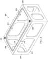
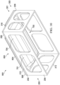
- portable structure 200 may be an example of one implementation for portable structure 121 in Figure 1 .
- portable structure 200 may include retaining structure 202 and support structure 204.
- Retaining structure 202 and support structure 204 may be examples of implementations for retaining structure 130 and support structure 138, respectively, in Figure 1 .
- support structure 204 may support retaining structure 202.
- retaining structure 202 may have first side 206 and second side 208.
- first side 206 may be a top side of retaining structure 202
- second side 208 may be a bottom side of retaining structure 202.
- support structure 204 may have first side 210 and second side 212.
- first side 210 may be a top side of support structure 204
- second side 212 may be a bottom side of support structure 204.
- retaining structure 202 may be attached to first side 210 of support structure 204.
- retaining structure 202 may have opening 214. Opening 214 may be configured to receive an object, such as, for example, without limitation, object 115 in Figure 1 .
- support structure 204 may have access openings 216. Access openings 216 may be configured to provide an operator with access to opening 214 of retaining structure 202 at second side 208 of retaining structure 202.
- vacuum attachment point 218 and vacuum attachment point 220 may be attachment points for vacuum ports (not shown) on retaining structure 202 of portable structure 200.
- vacuum attachment point 218 and vacuum attachment point 220 may be located on first side 206 of retaining structure 202.
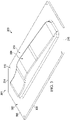
- object 300 may be an example of one implementation for object 115 in Figure 1 .
- object 300 may take the form of mandrel 301.
- mandrel 301 may be considered a male mandrel.
- mandrel 301 may have first portion 302 and second portion 304.
- Second portion 304 may be the portion of mandrel 301 used for shaping a workpiece (not shown) during curing.
- mandrel 301 may have first surface 306 and second surface 308.
- First surface 306 may have shape 310.
- shape 310 may be the shape of first surface 306 of second portion 304 of mandrel 301.
- Shape 310 may be an example of one implementation for shape 116 in Figure 1 .
- mandrel 301 may have plurality of holes 312. These holes may be used to attach mandrel 301 to retaining structure 202 of portable structure 200 in Figure 2 .
- fasteners (not shown) may be inserted into plurality of holes 312 to attach mandrel 301 to first side 206 of retaining structure 202 of portable structure 200 in Figure 2 .
- mandrel 301 may have cut corner 314 and cut corner 316.
- Cut corner 314 and cut corner 316 may be configured such that vacuum attachment point 218 and vacuum attachment point 220 on retaining structure 202 in Figure 2 may remain exposed when mandrel 301 is attached to retaining structure 202.
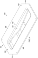
- FIG. 4 an illustration of a bottom isometric view of mandrel 301 from Figure 3 is depicted in accordance with an illustrative embodiment.
- shape 310 of first surface 306 of second portion 304 of mandrel 301 may form cavity 400 with respect to second surface 308 of mandrel 301.
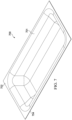
- FIG. 5 an illustration of a top isometric view of a composite workpiece laid over mandrel 301 from Figure 3 is depicted in accordance with an illustrative embodiment.
- composite workpiece 500 may be placed over mandrel 301.
- Composite workpiece 500 may be an example of one implementation for composite workpiece 108 in Figure 1 .
- composite workpiece 500 may be placed over first surface 306 of second portion 304 of mandrel 301 such that composite workpiece 500 substantially conforms to shape 310.
- composite workpiece 500 may cover only a portion of shape 310 of mandrel 301. Consequently, final shape 502 of composite workpiece 500 may be formed by only a portion of shape 310 of mandrel 301.
- Final shape 502 may be the final shape for the composite part to be formed by curing composite workpiece 500.
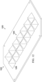
- heating device 600 may be an example of one implementation for first heating device 142 in Figure 1 .
- heating device 600 may take the form of thermal blanket 601.
- thermal blanket 601 may have first side 602 and second side 604.
- heating device 700 may be an example of one implementation for second heating device 144 in Figure 1 .
- heating device 700 may take the form of thermal bladder 701.
- thermal bladder 701 may have first side 702 and second side 704.
- curing assembly 800 may be formed using portable structure 200 from Figure 2 , mandrel 301 from Figures 3-5 , thermal blanket 601 from Figure 6 , thermal bladder 701 from Figure 7 , and gasket 801.
- Gasket 801 may be an example of one implementation for seal 136 in Figure 1 . Additionally, number of vacuum ports 802 may be considered part of a curing assembly 800 in this illustrative example. As depicted, number of vacuum ports 802 may include vacuum ports 804, 806, 808 and 810.
- Vacuum port 804 and vacuum port 806 may be attached to vacuum attachment point 218 and vacuum attachment point 220, respectively, on first side 206 of retaining structure 202 of portable structure 200. Further, vacuum port 808 and vacuum port 810 may be attached to vacuum attachment points (not shown) on first surface 306 of mandrel 301 when curing assembly 800 is assembled.
- first breather material 812 and second breather material 814 may also be used to form curing assembly 800.
- First breather material 812 may be positioned between thermal blanket 601 and mandrel 301.
- Second breather material 814 may be positioned between thermal bladder 701 and mandrel 301.
- First breather material 812 and second breather material 814 may be comprised of, for example, without limitation, wool. The wool may allow air to pass through these breather materials when a vacuum is applied using number of vacuum ports 802.
- thermal blanket 601 may cover first surface 306 of mandrel 301 at first side 206 of retaining structure 202.
- Thermal blanket 601 and thermal bladder 701 may together form heating system 900.
- Heating system 900 may be an example of one implementation for heating system 122 in Figure 1 .
- First breather material 812 and second breather material 814 from Figure 8 may not be shown in this view in Figure 9 .
- first breather material 812 and second breather material 814 from Figure 8 may be covered by thermal blanket 601 and thermal bladder 701, respectively.
- thermal bladder 701 may be more clearly seen.
- Thermal bladder 701 may cover second surface 308 of mandrel 301 at second side 208 of retaining structure 202.
- portable curing system 1100 may include curing assembly 800 from Figure 9 fully assembled, heating system 900, vacuum bag 1102, portable console 1104, and control system 1106.
- portable console 1104 may include a vacuum system (not shown) and a power system (not shown).
- This vacuum system (not shown) and power system (not shown) may be implemented using vacuum system 124 and power system 128, respectively, described in Figure 1 .
- Vacuum bag 1102 may be placed around curing assembly 800. Vacuum bag 1102 may substantially hermetically seal the space within vacuum bag 1102 such that a vacuum may be applied within vacuum bag 1102. This vacuum may be generated by the vacuum system (not shown) removing gas molecules from within vacuum bag 1102 through number of vacuum lines 1108 connected to number of vacuum ports 802. Number of vacuum lines 1108 may include vacuum lines 1110, 1112, 1114, and 1116 connected to vacuum ports 804, 806, 808, and 810, respectively.
- control system 1106 may be used to control the vacuum pressure generated by the vacuum system (not shown) within vacuum bag 1102. Control system 1106 may be also used to control the amount of heat generated by heating system 900. In this manner, the curing performed by the vacuum applied by the vacuum system and the heat provided by heating system 900 may be monitored and adjusted during the curing process as needed.
- Mandrel 1200 may an example of one implementation for object 115 in Figure 1 .
- mandrel 1200 may have first portion 1202 and second portion 1204.
- Second portion 1204 may have shape 1206.
- Shape 1206 may be different from shape 310 of mandrel 301 in Figure 1 .
- mandrel 1200 may be used in curing assembly 800 in Figures 8-11 instead of mandrel 301.
- the part (not shown) formed by curing a composite workpiece (not shown) laid over second portion 1204 of mandrel 1200 may be different from the shape of the part (not shown) formed by curing composite workpiece 500 laid over mandrel 301 in Figure 5 .
- the different components shown in Figures 2-12 may be illustrative examples of how components shown in block form in Figure 1 may be implemented as physical structures. Additionally, the different components shown in Figures 2-12 may be combined with components in Figure 1 , used with components in Figure 1 , or a combination of the two.
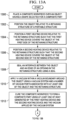
- FIG. 13 an illustration of a process for curing a composite workpiece to form a composite part in the form of a flowchart is depicted in accordance with an illustrative embodiment.
- the process illustrated in Figure 13 may be implemented using portable curing system 114 in Figure 1 . Further, this process may be implemented to cure composite workpiece 108 to form composite part 172 having final shape 119 in Figure 1 .
- the process may begin by placing composite workpiece 108 over object 115 having shape 116 selected for composite part 172 (operation 1300).
- Object 115 may be positioned relative to retaining structure 130 of portable structure 121 (operation 1302).
- retaining structure 130 may be configured to hold object 115 within opening 134 in retaining structure 130.
- Retaining structure 130 may have first side 131 and second side 132.
- first heating device 142 may be positioned relative to retaining structure 130 such that first heating device 142 covers object 115 at first side 131 of retaining structure 130 (operation 1304).
- a first breather material such as, for example, without limitation, first breather material 812 in Figure 8 , may be positioned relative to retaining structure 130 at first side 131 of retaining structure 130 prior to first heating device 142 being positioned relative to retaining structure 130. In this manner, first heating device 142 may cover both the first breather material and object 115.
- Second heating device 144 may be positioned relative to retaining structure 130 such that second heating device 144 covers object 115 at second side 132 of retaining structure 130 (operation 1306).
- a second breather material such as, for example, without limitation, second breather material 814 in Figure 8 , may be positioned relative to retaining structure 130 at second side 132 of retaining structure 130 prior to second heating device 144 being positioned relative to retaining structure 130. In this manner, second heating device 144 may cover both the second breather material and object 115.
- An interface between object 115 and edge 137 of opening 134 in retaining structure 130 may be sealed using seal 136 (operation 1308).
- Seal 136 may substantially hermetically seal this interface in operation 1308.
- vacuum 146 may be applied within vacuum boundary 154 around object 115 using vacuum system 124 and number of vacuum ports 148 associated with at least one of object 115 and retaining structure 130 (operation 1310).
- Composite workpiece 108 may be cured to form composite part 172 using at least one of heat 110 generated by first heating device 142 and second heating device 144 and vacuum 146 applied by vacuum system 124 (operation 1312).
- composite workpiece 108 may be monitored by generating sensor data 164 during the curing of composite workpiece 108 using sensor system 166 (operation 1314).
- Control system 126 may determine whether vacuum pressure 112 generated by vacuum system 124 to apply vacuum 146 and/or amount 162 of heat 110 generated by first heating device 142 and second heating device 144 need to be adjusted based on sensor data 164 (operation 1316). If vacuum pressure 112 and/or heat 110 need to be adjusted, control system 126 may control heating system 122 to adjust heat and/or vacuum system 124 to adjust vacuum pressure 112 (operation 1318).
- the process may determine whether the curing of composite workpiece 108 has been completed (operation 1320). If the curing of composite workpiece 108 has been completed, the process may terminate. The result of the curing process may be composite part 172 having final shape 119.
- each block in the flowcharts or block diagrams may represent a module, segment, function, and/or a portion of an operation or step.
- the function or functions noted in the blocks may occur out of the order noted in the figures.
- two blocks shown in succession may be executed substantially concurrently, or the blocks may sometimes be performed in the reverse order, depending upon the functionality involved.
- other blocks may be added in addition to the illustrated blocks in a flowchart or block diagram.
- aircraft manufacturing and service method 1400 may be described in the context of aircraft manufacturing and service method 1400 as shown in Figure 14 and aircraft 1500 as shown in Figure 15 .
- Figure 14 an illustration of an aircraft manufacturing and service method in the form of a block diagram is depicted in accordance with an illustrative embodiment.
- aircraft manufacturing and service method 1400 may include specification and design 1402 of aircraft 1500 in Figure 15 and material procurement 1404.
- aircraft 1500 in Figure 15 may go through certification and delivery 1410 in order to be placed in service 1412. While in service 1412 by a customer, aircraft 1500 in Figure 15 may be scheduled for routine maintenance and service 1414, which may include modification, reconfiguration, refurbishment, and other maintenance or service.
- Each of the processes of aircraft manufacturing and service method 1400 may be performed or carried out by a system integrator, a third party, and/or an operator.
- the operator may be a customer.
- a system integrator may include, without limitation, any number of aircraft manufacturers and major-system subcontractors
- a third party may include, without limitation, any number of vendors, subcontractors, and suppliers
- an operator may be an airline, a leasing company, a military entity, a service organization, and so on.
- aircraft 1500 may be produced by aircraft manufacturing and service method 1400 in Figure 14 and may include airframe 1502 with plurality of systems 1504 and interior 1506.
- systems 1504 may include one or more of propulsion system 1508, electrical system 1510, hydraulic system 1512, and environmental system 1514. Any number of other systems may be included.
- propulsion system 1508 electrical system 1510, hydraulic system 1512, and environmental system 1514. Any number of other systems may be included.
- an aerospace example is shown, different illustrative embodiments may be applied to other industries, such as the automotive industry.
- Apparatuses and methods embodied herein may be employed during at least one of the stages of aircraft manufacturing and service method 1400 in Figure 14 .
- components or subassemblies produced in component and subassembly manufacturing 1406 in Figure 14 may be fabricated or manufactured in a manner similar to components or subassemblies produced while aircraft 1500 is in service 1412 in Figure 14 .
- one or more apparatus embodiments, method embodiments, or a combination thereof may be utilized during production stages, such as component and subassembly manufacturing 1406 and system integration 1408 in Figure 14 .
- portable curing system 114 may be used to cure composite materials to form parts for aircraft 1500 during one or more of component and subassembly manufacturing 1406, system integration 1408, routine maintenance and service 1414 and other stages during the processes of aircraft manufacturing and service method 1400 in Figure 14 . Further, portable curing system 114 may be configured to move to different locations during these different stages.
- One or more apparatus embodiments, method embodiments, or a combination thereof may be utilized while aircraft 1500 is in service 1412 and/or during maintenance and service 1414 in Figure 14 .
- the use of a number of the different illustrative embodiments may substantially expedite the assembly of and/or reduce the cost of aircraft 1500.
Landscapes
- Mechanical Engineering (AREA)
- Engineering & Computer Science (AREA)
- Health & Medical Sciences (AREA)
- Oral & Maxillofacial Surgery (AREA)
- Thermal Sciences (AREA)
- Physics & Mathematics (AREA)
- Chemical & Material Sciences (AREA)
- Composite Materials (AREA)
- Organic Chemistry (AREA)
- Chemical Kinetics & Catalysis (AREA)
- Casting Or Compression Moulding Of Plastics Or The Like (AREA)
- Moulding By Coating Moulds (AREA)
- Heating, Cooling, Or Curing Plastics Or The Like In General (AREA)
Claims (15)
- Dispositif comprenant :un objet (115) présentant une forme (116) choisie pour une pièce (104) ;une structure portable (121) comprenant une structure de retenue (130) configurée pour retenir l'objet (115) dans laquelle la structure de retenue (130) présente un premier côté (131) et un second côté (132) ; etun système de chauffage (122) configuré pour couvrir l'objet (115) au niveau du premier côté (131) de la structure de retenue (130) et du second côté (132) de la structure de retenue (130) dans laquelle le système de chauffage (122) est configuré pour générer de la chaleur (110) destinée à être utilisée dans le durcissement d'une pièce de fabrication (102) placée sur l'objet (115) pour former la pièce (104),dans lequel le système de chauffage (122) comprend :un premier moyen de chauffage (142) configuré pour couvrir l'objet (115) au niveau du premier côté (131) de la structure de retenue (130) ; etun second moyen de chauffage (144) configuré pour couvrir l'objet (115) au niveau du second côté (132) de la structure de retenue (130),dans lequel au moins un moyen parmi le premier moyen de chauffage (142) et le second moyen de chauffage (144) est configuré pour se déformer en réponse à un vide (146), etdans lequel au moins un moyen parmi le premier moyen de chauffage (142) et le second moyen de chauffage (144) est composé d'un matériau déformable (158) choisi de telle sorte que l'au moins un moyen parmi le premier moyen de chauffage (142) et le second moyen de chauffage (144) se déforme en réponse au vide (146) pour se conformer à la forme (116) de l'objet (115),dans lequel le dispositif comprend en outre :un nombre d'orifices de vide (148) associés à l'au moins un élément parmi l'objet (115) et la structure de retenue (130) ; etun système de vide (124) relié au nombre d'orifices de vide (148) et configuré pour appliquer un vide (146) à l'intérieur d'une limite de vide (154) formée autour de l'objet (115) dans lequel le vide (146) est utilisé dans le durcissement de la pièce de fabrication (102) placée sur l'objet (115) pour former la pièce (104) .
- Dispositif selon la revendication 1, dans lequel la limite de vide (154) est formée par au moins un élément parmi le système de chauffage (122) et un sac sous vide (156).
- Dispositif selon la revendication 1, comprenant en outre :
un système de commande (126) configuré pour commander la pression de vide (112) générée par le système de vide (124) pour appliquer le vide (146) et une quantité (162) de la chaleur (110) générée par le système de chauffage (122). - Dispositif selon une quelconque revendication précédente, dans lequel la structure de retenue (130) de la structure portable (121) comprend une ouverture (134) configurée pour recevoir et retenir l'objet (115) et comprenant en outre :
un joint d'étanchéité (136) configuré pour étanchéifier (136) une interface entre l'objet (115) et un bord (137) de l'ouverture (134) de la structure de retenue (130). - Dispositif selon une quelconque revendication précédente comprenant en outre :
un système de capteur (166) associé à l'au moins un élément parmi l'objet (115) et le système de chauffage (122), dans lequel le système de capteur (166) est configuré pour générer des données de capteur (164) pendant le durcissement de la pièce de fabrication (102). - Dispositif selon une quelconque revendication précédente, dans lequel l'objet prend la forme d'un mandrin (301).
- Dispositif selon une quelconque revendication précédente, dans lequel le premier moyen de chauffage (142) prend la forme d'un revêtement thermique (601).
- Dispositif selon une quelconque revendication précédente, dans lequel le second moyen de chauffage (144) prend la forme d'un vessie thermique (701).
- Procédé destiné au durcissement d'une pièce de fabrication (102) pour former une pièce (104), le procédé comprenant :le placement de la pièce de fabrication (102) sur un objet (115) présentant une forme (116) choisie pour la pièce (104) ;le positionnement de l'objet (115) par rapport à une structure de retenue (130) configurée pour retenir l'objet (115) dans laquelle la structure de retenue (130) présente un premier côté (131) et un second côté (132) ;le positionnement d'un système de chauffage (122) par rapport à la structure de retenue (130) de telle sorte que le système de chauffage (122) couvre l'objet (115) au niveau du premier côté (131) de la structure de retenue (130) et au niveau du second côté (132) de la structure de retenue (130) ; etle durcissement de la pièce de fabrication (102) pour former la pièce (104) en utilisant la chaleur (110) générée par le système de chauffage (122),dans lequel l'étape de positionnement du système de chauffage (122) par rapport à la structure de retenue (130) comprend :le positionnement d'un premier moyen de chauffage (142) sur l'objet (115) au niveau du premier côté (131) de la structure de retenue (130) ; etle positionnement d'un second moyen de chauffage (144) sur l'objet (115) au niveau du second côté (132) de la structure de retenue (130),dans lequel au moins un moyen parmi le premier moyen de chauffage (142) et le second moyen de chauffage (144) est composé d'un matériau déformable (158), etle procédé comprend en outre :
l'application d'un vide (146) à l'intérieur d'une limite de vide (154) autour de l'objet (115) en utilisant un système de vide (124), dans lequel le vide (146) est utilisé dans le durcissement de la pièce de fabrication (102) pour former la pièce (104), dans lequel au moins un moyen parmi le premier moyen de chauffage (144) et le second moyen de chauffage (144) se déforme en réponse au vide (146) pour se conformer à la forme (116) de l'objet (115) . - Procédé selon la revendication 9, dans lequel l'étape d'application du vide (146) à l'intérieur de la limite de vide (154) autour de l'objet (115) comprend :
l'application du vide (146) à l'intérieur de la limite de vide (154) autour de l'objet (115) en utilisant un nombre d'orifices de vide (148) associés à l'au moins un élément parmi l'objet (115) et la structure de retenue (130). - Procédé selon la revendication 9 ou 10, comprenant en outre :la génération de données de capteur (164) pendant le durcissement de la pièce de fabrication (102) en utilisant un système de capteur (166) ; etla commande de la pression de vide (112) générée par le système de vide (124) pour appliquer le vide (146) et une quantité (162) de la chaleur (110) générée par le système de chauffage (122) sur la base des données de capteur (164) générées par le système de capteur (166) en utilisant un système de commande (126).
- Procédé selon une quelconque des revendications 9 à 11, comprenant en outre :
l'étanchéification d'une interface entre l'objet (115) et un bord (137) d'une ouverture (134) dans la structure de retenue (130) configurée pour recevoir l'objet (115) en utilisant un joint d'étanchéité (136). - Procédé selon une quelconque des revendications 9 à 12, dans lequel l'étape de durcissement de la pièce de fabrication (102) pour former la pièce (104) en utilisant la chaleur (110) générée par le système de chauffage (122) comprend :
le durcissement d'une pièce de fabrication composite (108) pour former une pièce composite (172) en utilisant la chaleur (110) générée par le système de chauffage (122), dans lequel la pièce composite (172) présente une forme finale (119) qui correspond sensiblement au moins à une portion de la forme (116) de l'objet (115) . - Procédé selon une quelconque des revendications 9 à 13, dans lequel l'objet prend la forme d'un mandrin (301).
- Procédé selon une quelconque des revendications 9 à 14, dans lequel le premier moyen de chauffage (142) prend la forme d'un revêtement thermique (601).
Applications Claiming Priority (1)
| Application Number | Priority Date | Filing Date | Title |
|---|---|---|---|
| US13/586,032 US9649785B2 (en) | 2012-08-15 | 2012-08-15 | Portable Curing System |
Publications (3)
| Publication Number | Publication Date |
|---|---|
| EP2698242A1 EP2698242A1 (fr) | 2014-02-19 |
| EP2698242B1 true EP2698242B1 (fr) | 2023-03-15 |
| EP2698242B8 EP2698242B8 (fr) | 2023-03-22 |
Family
ID=48747945
Family Applications (1)
| Application Number | Title | Priority Date | Filing Date |
|---|---|---|---|
| EP13174299.1A Active EP2698242B8 (fr) | 2012-08-15 | 2013-06-28 | Système de durcissement portable |
Country Status (8)
| Country | Link |
|---|---|
| US (3) | US9649785B2 (fr) |
| EP (1) | EP2698242B8 (fr) |
| JP (1) | JP6214276B2 (fr) |
| KR (1) | KR102123124B1 (fr) |
| CN (1) | CN103587129B (fr) |
| BR (1) | BR102013020686B1 (fr) |
| CA (1) | CA2818638C (fr) |
| RU (1) | RU2640538C2 (fr) |
Families Citing this family (5)
| Publication number | Priority date | Publication date | Assignee | Title |
|---|---|---|---|---|
| US9649785B2 (en) | 2012-08-15 | 2017-05-16 | The Boeing Company | Portable Curing System |
| GB2535193A (en) * | 2015-02-12 | 2016-08-17 | Zodiac Seats Uk Ltd | Tool for curing a composite component |
| US10927543B2 (en) * | 2017-06-19 | 2021-02-23 | The Boeing Company | Acoustic attenuation structure |
| CN111301872A (zh) * | 2018-12-11 | 2020-06-19 | 汉能移动能源控股集团有限公司 | 一种层状加热单元、层状加热结构和层压袋 |
| CN112246572A (zh) * | 2020-09-15 | 2021-01-22 | 深圳供电局有限公司 | 固化装置 |
Citations (3)
| Publication number | Priority date | Publication date | Assignee | Title |
|---|---|---|---|---|
| GB940407A (en) * | 1961-03-29 | 1963-10-30 | Ford Motor Co | Method of shaping a sheet material containing a heat deformable component |
| US5630894A (en) * | 1995-02-23 | 1997-05-20 | Gemstone Memorials, Inc. | Flexible heating pad for transfer of decalcomania |
| US20080261046A1 (en) * | 2004-03-30 | 2008-10-23 | Plastxform Ag | Method For Producing Molded Bodies From Thermoplastic Material |
Family Cites Families (23)
| Publication number | Priority date | Publication date | Assignee | Title |
|---|---|---|---|---|
| BE627232A (fr) | 1962-12-29 | |||
| US3682571A (en) * | 1970-05-28 | 1972-08-08 | Samuel Greenberg | Semi-automatic apparatus for molding plastic copings and similar articles |
| US3689728A (en) | 1971-08-19 | 1972-09-05 | Willcox & Gibbs Inc | Continuous production dielectric heating apparats |
| GB1403392A (en) * | 1971-08-19 | 1975-08-28 | Willcox & Gibbs Inc | Method of manufacturing lightweight bodies of expanded heat- settable resin |
| CA1284007C (fr) * | 1986-02-13 | 1991-05-14 | Robert V. Kromrey | Methode et dispositif de moulage par recours a un polymere solide coulant |
| US4846908A (en) * | 1987-04-03 | 1989-07-11 | E. I. Du Pont De Nemours And Company | Process for preparing a fiber reinforced resin matrix preform |
| JPS63251207A (ja) * | 1987-04-07 | 1988-10-18 | Ashida Seisakusho:Kk | プリント配線板の成形方法及びその装置 |
| GB8916909D0 (en) | 1989-07-24 | 1989-09-06 | Ici Plc | Method of forming thermoformable composite material |
| US5106282A (en) | 1989-12-18 | 1992-04-21 | Fmc Corporation | Apparatus for rapidly laying up, and curing thick complex shaped resin matrix composites |
| US5122323A (en) | 1989-12-18 | 1992-06-16 | Sullivan Sr Fletcher R | Method for rapidly laying up and curing thick complex resin matrix composites |
| US5464337A (en) | 1991-03-27 | 1995-11-07 | The Charles Stark Draper Laboratories | Resin transfer molding system |
| JP2582335B2 (ja) * | 1993-12-25 | 1997-02-19 | 株式会社島津 | 繊維強化プラスチック成形品の成形方法及びその成形装置 |
| DE69526171T2 (de) | 1994-10-31 | 2002-11-14 | Mitsubishi Jukogyo K.K., Tokio/Tokyo | Reifenvulkanisiervorrichtung |
| JP3181180B2 (ja) * | 1994-10-31 | 2001-07-03 | 三菱重工業株式会社 | タイヤ加硫設備 |
| GB2322823A (en) * | 1997-03-07 | 1998-09-09 | Aerovac Systems | Heated vacuum bag |
| WO2000054949A2 (fr) | 1999-03-10 | 2000-09-21 | Southern Research Institute | Appareil d'outillage chauffe et procede de traitement de materiau composite et plastique |
| US6207118B1 (en) | 1999-07-20 | 2001-03-27 | Thomas J. Gaven | Mobile ultraviolet radiation curing device |
| JP3574604B2 (ja) * | 2000-04-04 | 2004-10-06 | 株式会社名機製作所 | 真空積層方法とそのための装置 |
| DE102009001075A1 (de) | 2009-02-23 | 2010-09-09 | Airbus Deutschland Gmbh | Verfahren zum zumindest teilweise Nachbearbeiten oder Ersetzen eines Versteifungselementes einer Faserverbundstruktur und zugehörige Anbindvorrichtung |
| CN106079479B (zh) * | 2010-11-05 | 2019-09-06 | 轻量实验室有限责任公司 | 热处理和固化系统及方法 |
| KR102037237B1 (ko) * | 2010-11-05 | 2019-10-28 | 라이트웨이트 랩스, 엘엘씨 | 열처리 강화 시스템 및 방법 |
| WO2012075252A1 (fr) * | 2010-12-01 | 2012-06-07 | Plasan Carbon Composites, Inc. | Procédé et système permettant de former des articles composites |
| US9649785B2 (en) | 2012-08-15 | 2017-05-16 | The Boeing Company | Portable Curing System |
-
2012
- 2012-08-15 US US13/586,032 patent/US9649785B2/en active Active
-
2013
- 2013-06-11 CA CA2818638A patent/CA2818638C/fr active Active
- 2013-06-24 KR KR1020130072394A patent/KR102123124B1/ko active Active
- 2013-06-28 EP EP13174299.1A patent/EP2698242B8/fr active Active
- 2013-07-03 RU RU2013130323A patent/RU2640538C2/ru active
- 2013-08-13 JP JP2013167953A patent/JP6214276B2/ja active Active
- 2013-08-14 BR BR102013020686-5A patent/BR102013020686B1/pt active IP Right Grant
- 2013-08-15 CN CN201310356064.0A patent/CN103587129B/zh active Active
-
2017
- 2017-04-11 US US15/484,227 patent/US10112350B2/en active Active
-
2018
- 2018-10-29 US US16/173,123 patent/US10464270B2/en active Active
Patent Citations (3)
| Publication number | Priority date | Publication date | Assignee | Title |
|---|---|---|---|---|
| GB940407A (en) * | 1961-03-29 | 1963-10-30 | Ford Motor Co | Method of shaping a sheet material containing a heat deformable component |
| US5630894A (en) * | 1995-02-23 | 1997-05-20 | Gemstone Memorials, Inc. | Flexible heating pad for transfer of decalcomania |
| US20080261046A1 (en) * | 2004-03-30 | 2008-10-23 | Plastxform Ag | Method For Producing Molded Bodies From Thermoplastic Material |
Also Published As
| Publication number | Publication date |
|---|---|
| US20140048966A1 (en) | 2014-02-20 |
| EP2698242B8 (fr) | 2023-03-22 |
| BR102013020686A2 (pt) | 2014-11-25 |
| RU2640538C2 (ru) | 2018-01-09 |
| KR20140022725A (ko) | 2014-02-25 |
| JP6214276B2 (ja) | 2017-10-18 |
| RU2013130323A (ru) | 2015-01-10 |
| US9649785B2 (en) | 2017-05-16 |
| US20190061283A1 (en) | 2019-02-28 |
| CN103587129A (zh) | 2014-02-19 |
| CA2818638A1 (fr) | 2014-02-15 |
| US10464270B2 (en) | 2019-11-05 |
| JP2014058153A (ja) | 2014-04-03 |
| CA2818638C (fr) | 2015-11-10 |
| US10112350B2 (en) | 2018-10-30 |
| EP2698242A1 (fr) | 2014-02-19 |
| KR102123124B1 (ko) | 2020-06-16 |
| US20170225408A1 (en) | 2017-08-10 |
| BR102013020686B1 (pt) | 2020-05-26 |
| CN103587129B (zh) | 2021-07-09 |
Similar Documents
| Publication | Publication Date | Title |
|---|---|---|
| US10464270B2 (en) | Portable curing system | |
| US7691222B2 (en) | Flexible tooling method and apparatus | |
| EP2508329B1 (fr) | Appareil et procédé de consolidation de composite par induction | |
| EP2512783B1 (fr) | Procédé de traitement sous vide double de pièces composites | |
| JP7066430B2 (ja) | 一体化複合構造製造システム | |
| EP3498465B1 (fr) | Cellule de chauffage par induction avec son procédé d'utilisation par plaques sur mandrins | |
| US20190191495A1 (en) | Induction heating cells with controllable thermal expansion of bladders and methods of using thereof | |
| EP3738754B1 (fr) | Moulage d'une structure composite avec une vessie superplastique | |
| EP3835042B1 (fr) | Système et procédé de traitement thermique et de consolidation | |
| JP2022080870A (ja) | 複合構造を処理するための装置及び方法 | |
| EP4331819B1 (fr) | Structure de contrôle dimensionnel pour durcir un panneau composite, système de durcissement par induction et procédé de durcissement d'un panneau composite | |
| JP2025175957A (ja) | 複合材構造体を硬化するためのシステム及び方法 |
Legal Events
| Date | Code | Title | Description |
|---|---|---|---|
| 17P | Request for examination filed |
Effective date: 20130628 |
|
| AK | Designated contracting states |
Kind code of ref document: A1 Designated state(s): AL AT BE BG CH CY CZ DE DK EE ES FI FR GB GR HR HU IE IS IT LI LT LU LV MC MK MT NL NO PL PT RO RS SE SI SK SM TR |
|
| AX | Request for extension of the european patent |
Extension state: BA ME |
|
| PUAI | Public reference made under article 153(3) epc to a published international application that has entered the european phase |
Free format text: ORIGINAL CODE: 0009012 |
|
| STAA | Information on the status of an ep patent application or granted ep patent |
Free format text: STATUS: EXAMINATION IS IN PROGRESS |
|
| 17Q | First examination report despatched |
Effective date: 20170710 |
|
| GRAP | Despatch of communication of intention to grant a patent |
Free format text: ORIGINAL CODE: EPIDOSNIGR1 |
|
| STAA | Information on the status of an ep patent application or granted ep patent |
Free format text: STATUS: GRANT OF PATENT IS INTENDED |
|
| INTG | Intention to grant announced |
Effective date: 20221014 |
|
| GRAS | Grant fee paid |
Free format text: ORIGINAL CODE: EPIDOSNIGR3 |
|
| GRAA | (expected) grant |
Free format text: ORIGINAL CODE: 0009210 |
|
| STAA | Information on the status of an ep patent application or granted ep patent |
Free format text: STATUS: THE PATENT HAS BEEN GRANTED |
|
| GRAM | Information related to correction after decision after decision to grant or to maintain patent in amended form deleted |
Free format text: ORIGINAL CODE: EPIDOSDCDEC |
|
| GRAT | Correction requested after decision to grant or after decision to maintain patent in amended form |
Free format text: ORIGINAL CODE: EPIDOSNCDEC |
|
| REG | Reference to a national code |
Ref country code: DE Ref legal event code: R081 Ref document number: 602013083448 Country of ref document: DE Owner name: THE BOEING COMPANY, ARLINGTON, US Free format text: FORMER OWNER: THE BOEING COMPANY, CHICAGO, IL, US |
|
| AK | Designated contracting states |
Kind code of ref document: B1 Designated state(s): AL AT BE BG CH CY CZ DE DK EE ES FI FR GB GR HR HU IE IS IT LI LT LU LV MC MK MT NL NO PL PT RO RS SE SI SK SM TR |
|
| REG | Reference to a national code |
Ref country code: CH Ref legal event code: EP Ref country code: GB Ref legal event code: FG4D |
|
| RAP4 | Party data changed (patent owner data changed or rights of a patent transferred) |
Owner name: THE BOEING COMPANY |
|
| REG | Reference to a national code |
Ref country code: DE Ref legal event code: R096 Ref document number: 602013083448 Country of ref document: DE |
|
| REG | Reference to a national code |
Ref country code: IE Ref legal event code: FG4D |
|
| REG | Reference to a national code |
Ref country code: AT Ref legal event code: REF Ref document number: 1553747 Country of ref document: AT Kind code of ref document: T Effective date: 20230415 |
|
| P01 | Opt-out of the competence of the unified patent court (upc) registered |
Effective date: 20230516 |
|
| REG | Reference to a national code |
Ref country code: LT Ref legal event code: MG9D |
|
| REG | Reference to a national code |
Ref country code: NL Ref legal event code: MP Effective date: 20230315 |
|
| PG25 | Lapsed in a contracting state [announced via postgrant information from national office to epo] |
Ref country code: RS Free format text: LAPSE BECAUSE OF FAILURE TO SUBMIT A TRANSLATION OF THE DESCRIPTION OR TO PAY THE FEE WITHIN THE PRESCRIBED TIME-LIMIT Effective date: 20230315 Ref country code: NO Free format text: LAPSE BECAUSE OF FAILURE TO SUBMIT A TRANSLATION OF THE DESCRIPTION OR TO PAY THE FEE WITHIN THE PRESCRIBED TIME-LIMIT Effective date: 20230615 Ref country code: LV Free format text: LAPSE BECAUSE OF FAILURE TO SUBMIT A TRANSLATION OF THE DESCRIPTION OR TO PAY THE FEE WITHIN THE PRESCRIBED TIME-LIMIT Effective date: 20230315 Ref country code: LT Free format text: LAPSE BECAUSE OF FAILURE TO SUBMIT A TRANSLATION OF THE DESCRIPTION OR TO PAY THE FEE WITHIN THE PRESCRIBED TIME-LIMIT Effective date: 20230315 Ref country code: HR Free format text: LAPSE BECAUSE OF FAILURE TO SUBMIT A TRANSLATION OF THE DESCRIPTION OR TO PAY THE FEE WITHIN THE PRESCRIBED TIME-LIMIT Effective date: 20230315 |
|
| REG | Reference to a national code |
Ref country code: AT Ref legal event code: MK05 Ref document number: 1553747 Country of ref document: AT Kind code of ref document: T Effective date: 20230315 |
|
| PG25 | Lapsed in a contracting state [announced via postgrant information from national office to epo] |
Ref country code: SE Free format text: LAPSE BECAUSE OF FAILURE TO SUBMIT A TRANSLATION OF THE DESCRIPTION OR TO PAY THE FEE WITHIN THE PRESCRIBED TIME-LIMIT Effective date: 20230315 Ref country code: NL Free format text: LAPSE BECAUSE OF FAILURE TO SUBMIT A TRANSLATION OF THE DESCRIPTION OR TO PAY THE FEE WITHIN THE PRESCRIBED TIME-LIMIT Effective date: 20230315 Ref country code: GR Free format text: LAPSE BECAUSE OF FAILURE TO SUBMIT A TRANSLATION OF THE DESCRIPTION OR TO PAY THE FEE WITHIN THE PRESCRIBED TIME-LIMIT Effective date: 20230616 Ref country code: FI Free format text: LAPSE BECAUSE OF FAILURE TO SUBMIT A TRANSLATION OF THE DESCRIPTION OR TO PAY THE FEE WITHIN THE PRESCRIBED TIME-LIMIT Effective date: 20230315 |
|
| PG25 | Lapsed in a contracting state [announced via postgrant information from national office to epo] |
Ref country code: SM Free format text: LAPSE BECAUSE OF FAILURE TO SUBMIT A TRANSLATION OF THE DESCRIPTION OR TO PAY THE FEE WITHIN THE PRESCRIBED TIME-LIMIT Effective date: 20230315 Ref country code: RO Free format text: LAPSE BECAUSE OF FAILURE TO SUBMIT A TRANSLATION OF THE DESCRIPTION OR TO PAY THE FEE WITHIN THE PRESCRIBED TIME-LIMIT Effective date: 20230315 Ref country code: PT Free format text: LAPSE BECAUSE OF FAILURE TO SUBMIT A TRANSLATION OF THE DESCRIPTION OR TO PAY THE FEE WITHIN THE PRESCRIBED TIME-LIMIT Effective date: 20230717 Ref country code: ES Free format text: LAPSE BECAUSE OF FAILURE TO SUBMIT A TRANSLATION OF THE DESCRIPTION OR TO PAY THE FEE WITHIN THE PRESCRIBED TIME-LIMIT Effective date: 20230315 Ref country code: EE Free format text: LAPSE BECAUSE OF FAILURE TO SUBMIT A TRANSLATION OF THE DESCRIPTION OR TO PAY THE FEE WITHIN THE PRESCRIBED TIME-LIMIT Effective date: 20230315 Ref country code: CZ Free format text: LAPSE BECAUSE OF FAILURE TO SUBMIT A TRANSLATION OF THE DESCRIPTION OR TO PAY THE FEE WITHIN THE PRESCRIBED TIME-LIMIT Effective date: 20230315 Ref country code: AT Free format text: LAPSE BECAUSE OF FAILURE TO SUBMIT A TRANSLATION OF THE DESCRIPTION OR TO PAY THE FEE WITHIN THE PRESCRIBED TIME-LIMIT Effective date: 20230315 |
|
| PG25 | Lapsed in a contracting state [announced via postgrant information from national office to epo] |
Ref country code: SK Free format text: LAPSE BECAUSE OF FAILURE TO SUBMIT A TRANSLATION OF THE DESCRIPTION OR TO PAY THE FEE WITHIN THE PRESCRIBED TIME-LIMIT Effective date: 20230315 Ref country code: PL Free format text: LAPSE BECAUSE OF FAILURE TO SUBMIT A TRANSLATION OF THE DESCRIPTION OR TO PAY THE FEE WITHIN THE PRESCRIBED TIME-LIMIT Effective date: 20230315 Ref country code: IS Free format text: LAPSE BECAUSE OF FAILURE TO SUBMIT A TRANSLATION OF THE DESCRIPTION OR TO PAY THE FEE WITHIN THE PRESCRIBED TIME-LIMIT Effective date: 20230715 |
|
| REG | Reference to a national code |
Ref country code: DE Ref legal event code: R097 Ref document number: 602013083448 Country of ref document: DE |
|
| PG25 | Lapsed in a contracting state [announced via postgrant information from national office to epo] |
Ref country code: MC Free format text: LAPSE BECAUSE OF FAILURE TO SUBMIT A TRANSLATION OF THE DESCRIPTION OR TO PAY THE FEE WITHIN THE PRESCRIBED TIME-LIMIT Effective date: 20230315 |
|
| PLBE | No opposition filed within time limit |
Free format text: ORIGINAL CODE: 0009261 |
|
| STAA | Information on the status of an ep patent application or granted ep patent |
Free format text: STATUS: NO OPPOSITION FILED WITHIN TIME LIMIT |
|
| PG25 | Lapsed in a contracting state [announced via postgrant information from national office to epo] |
Ref country code: SI Free format text: LAPSE BECAUSE OF FAILURE TO SUBMIT A TRANSLATION OF THE DESCRIPTION OR TO PAY THE FEE WITHIN THE PRESCRIBED TIME-LIMIT Effective date: 20230315 Ref country code: MC Free format text: LAPSE BECAUSE OF FAILURE TO SUBMIT A TRANSLATION OF THE DESCRIPTION OR TO PAY THE FEE WITHIN THE PRESCRIBED TIME-LIMIT Effective date: 20230315 Ref country code: DK Free format text: LAPSE BECAUSE OF FAILURE TO SUBMIT A TRANSLATION OF THE DESCRIPTION OR TO PAY THE FEE WITHIN THE PRESCRIBED TIME-LIMIT Effective date: 20230315 |
|
| REG | Reference to a national code |
Ref country code: CH Ref legal event code: PL |
|
| 26N | No opposition filed |
Effective date: 20231218 |
|
| REG | Reference to a national code |
Ref country code: BE Ref legal event code: MM Effective date: 20230630 |
|
| PG25 | Lapsed in a contracting state [announced via postgrant information from national office to epo] |
Ref country code: LU Free format text: LAPSE BECAUSE OF NON-PAYMENT OF DUE FEES Effective date: 20230628 |
|
| REG | Reference to a national code |
Ref country code: IE Ref legal event code: MM4A |
|
| PG25 | Lapsed in a contracting state [announced via postgrant information from national office to epo] |
Ref country code: LU Free format text: LAPSE BECAUSE OF NON-PAYMENT OF DUE FEES Effective date: 20230628 |
|
| PG25 | Lapsed in a contracting state [announced via postgrant information from national office to epo] |
Ref country code: IE Free format text: LAPSE BECAUSE OF NON-PAYMENT OF DUE FEES Effective date: 20230628 |
|
| PG25 | Lapsed in a contracting state [announced via postgrant information from national office to epo] |
Ref country code: IE Free format text: LAPSE BECAUSE OF NON-PAYMENT OF DUE FEES Effective date: 20230628 Ref country code: CH Free format text: LAPSE BECAUSE OF NON-PAYMENT OF DUE FEES Effective date: 20230630 |
|
| PG25 | Lapsed in a contracting state [announced via postgrant information from national office to epo] |
Ref country code: IT Free format text: LAPSE BECAUSE OF FAILURE TO SUBMIT A TRANSLATION OF THE DESCRIPTION OR TO PAY THE FEE WITHIN THE PRESCRIBED TIME-LIMIT Effective date: 20230315 Ref country code: BE Free format text: LAPSE BECAUSE OF NON-PAYMENT OF DUE FEES Effective date: 20230630 |
|
| PG25 | Lapsed in a contracting state [announced via postgrant information from national office to epo] |
Ref country code: BG Free format text: LAPSE BECAUSE OF FAILURE TO SUBMIT A TRANSLATION OF THE DESCRIPTION OR TO PAY THE FEE WITHIN THE PRESCRIBED TIME-LIMIT Effective date: 20230315 |
|
| PG25 | Lapsed in a contracting state [announced via postgrant information from national office to epo] |
Ref country code: BG Free format text: LAPSE BECAUSE OF FAILURE TO SUBMIT A TRANSLATION OF THE DESCRIPTION OR TO PAY THE FEE WITHIN THE PRESCRIBED TIME-LIMIT Effective date: 20230315 |
|
| PGFP | Annual fee paid to national office [announced via postgrant information from national office to epo] |
Ref country code: DE Payment date: 20250627 Year of fee payment: 13 |
|
| PGFP | Annual fee paid to national office [announced via postgrant information from national office to epo] |
Ref country code: GB Payment date: 20250627 Year of fee payment: 13 |
|
| PGFP | Annual fee paid to national office [announced via postgrant information from national office to epo] |
Ref country code: FR Payment date: 20250625 Year of fee payment: 13 |
|
| PG25 | Lapsed in a contracting state [announced via postgrant information from national office to epo] |
Ref country code: CY Free format text: LAPSE BECAUSE OF FAILURE TO SUBMIT A TRANSLATION OF THE DESCRIPTION OR TO PAY THE FEE WITHIN THE PRESCRIBED TIME-LIMIT; INVALID AB INITIO Effective date: 20130628 |
|
| PG25 | Lapsed in a contracting state [announced via postgrant information from national office to epo] |
Ref country code: HU Free format text: LAPSE BECAUSE OF FAILURE TO SUBMIT A TRANSLATION OF THE DESCRIPTION OR TO PAY THE FEE WITHIN THE PRESCRIBED TIME-LIMIT; INVALID AB INITIO Effective date: 20130628 |
|
| PG25 | Lapsed in a contracting state [announced via postgrant information from national office to epo] |
Ref country code: TR Free format text: LAPSE BECAUSE OF FAILURE TO SUBMIT A TRANSLATION OF THE DESCRIPTION OR TO PAY THE FEE WITHIN THE PRESCRIBED TIME-LIMIT Effective date: 20230315 |