EP2698332A2 - Dispositif d'enroulement d'un matériau en forme de bande sur des bobines - Google Patents
Dispositif d'enroulement d'un matériau en forme de bande sur des bobines Download PDFInfo
- Publication number
- EP2698332A2 EP2698332A2 EP13003624.7A EP13003624A EP2698332A2 EP 2698332 A2 EP2698332 A2 EP 2698332A2 EP 13003624 A EP13003624 A EP 13003624A EP 2698332 A2 EP2698332 A2 EP 2698332A2
- Authority
- EP
- European Patent Office
- Prior art keywords
- rotary body
- rotary
- end position
- winding axis
- winding
- Prior art date
- Legal status (The legal status is an assumption and is not a legal conclusion. Google has not performed a legal analysis and makes no representation as to the accuracy of the status listed.)
- Granted
Links
Images


Classifications
-
- B—PERFORMING OPERATIONS; TRANSPORTING
- B65—CONVEYING; PACKING; STORING; HANDLING THIN OR FILAMENTARY MATERIAL
- B65H—HANDLING THIN OR FILAMENTARY MATERIAL, e.g. SHEETS, WEBS, CABLES
- B65H18/00—Winding webs
- B65H18/08—Web-winding mechanisms
-
- B—PERFORMING OPERATIONS; TRANSPORTING
- B65—CONVEYING; PACKING; STORING; HANDLING THIN OR FILAMENTARY MATERIAL
- B65H—HANDLING THIN OR FILAMENTARY MATERIAL, e.g. SHEETS, WEBS, CABLES
- B65H19/00—Changing the web roll
- B65H19/22—Changing the web roll in winding mechanisms or in connection with winding operations
- B65H19/2207—Changing the web roll in winding mechanisms or in connection with winding operations the web roll being driven by a winding mechanism of the centre or core drive type
-
- B—PERFORMING OPERATIONS; TRANSPORTING
- B65—CONVEYING; PACKING; STORING; HANDLING THIN OR FILAMENTARY MATERIAL
- B65H—HANDLING THIN OR FILAMENTARY MATERIAL, e.g. SHEETS, WEBS, CABLES
- B65H18/00—Winding webs
- B65H18/08—Web-winding mechanisms
- B65H18/10—Mechanisms in which power is applied to web-roll spindle
-
- B—PERFORMING OPERATIONS; TRANSPORTING
- B65—CONVEYING; PACKING; STORING; HANDLING THIN OR FILAMENTARY MATERIAL
- B65H—HANDLING THIN OR FILAMENTARY MATERIAL, e.g. SHEETS, WEBS, CABLES
- B65H19/00—Changing the web roll
- B65H19/22—Changing the web roll in winding mechanisms or in connection with winding operations
- B65H19/2207—Changing the web roll in winding mechanisms or in connection with winding operations the web roll being driven by a winding mechanism of the centre or core drive type
- B65H19/2215—Turret-type with two roll supports
-
- B—PERFORMING OPERATIONS; TRANSPORTING
- B65—CONVEYING; PACKING; STORING; HANDLING THIN OR FILAMENTARY MATERIAL
- B65H—HANDLING THIN OR FILAMENTARY MATERIAL, e.g. SHEETS, WEBS, CABLES
- B65H19/00—Changing the web roll
- B65H19/22—Changing the web roll in winding mechanisms or in connection with winding operations
- B65H19/2207—Changing the web roll in winding mechanisms or in connection with winding operations the web roll being driven by a winding mechanism of the centre or core drive type
- B65H19/223—Changing the web roll in winding mechanisms or in connection with winding operations the web roll being driven by a winding mechanism of the centre or core drive type with roll supports being independently displaceable along a common path
-
- B—PERFORMING OPERATIONS; TRANSPORTING
- B65—CONVEYING; PACKING; STORING; HANDLING THIN OR FILAMENTARY MATERIAL
- B65H—HANDLING THIN OR FILAMENTARY MATERIAL, e.g. SHEETS, WEBS, CABLES
- B65H2301/00—Handling processes for sheets or webs
- B65H2301/40—Type of handling process
- B65H2301/41—Winding, unwinding
- B65H2301/413—Supporting web roll
- B65H2301/4136—Mounting arrangements not otherwise provided for
- B65H2301/41368—Mounting arrangements not otherwise provided for one or two lateral flanges covering part of or entire web diameter
- B65H2301/413683—Mounting arrangements not otherwise provided for one or two lateral flanges covering part of or entire web diameter at least one flange transmitting driving force
-
- B—PERFORMING OPERATIONS; TRANSPORTING
- B65—CONVEYING; PACKING; STORING; HANDLING THIN OR FILAMENTARY MATERIAL
- B65H—HANDLING THIN OR FILAMENTARY MATERIAL, e.g. SHEETS, WEBS, CABLES
- B65H2701/00—Handled material; Storage means
- B65H2701/10—Handled articles or webs
- B65H2701/19—Specific article or web
- B65H2701/1942—Web supporting regularly spaced non-adhesive articles
Definitions
- the invention relates to a device for winding strip-shaped material according to claim 1.
- contact elements for electrical engineering are now produced in large quantities by punching.
- the contact elements leave the punching machine attached to at least one carrier strip so that a band-shaped material is present, which consists of the aforementioned at least one carrier strip and the stamped contact parts.
- the strip-shaped material is wound onto coils. Cardboard bobbins are often used for this purpose.
- cardboard spools have the advantage of a low price and a low weight, which keeps the transport costs low. They also have the advantage that they can be recycled immediately after use.
- Such a cardboard spool has a spool core and two circular side walls, which are held on the spool core and, ideally, extend parallel to one another.
- a device for winding the strip-like material on such a coil has in the simplest case a drive motor which can set a rotary body in rotation. From this rotary body extends a shaft on which the coil is attached. From the rotary body further extend, for example, mandrels, which drill in a side wall of such a cardboard spool, so that a temporary rotationally fixed connection between the rotary body and the cardboard spool is formed.
- the coils, when full, are changed by a person by hand.
- a problem that often occurs with the use of the above-mentioned cardboard reels is that the parallelism of the side walls is not ideally preserved, namely such that the side walls are slightly wavy, especially in the edge region. In the worst case, this can lead to the band-shaped material to be wound becoming caught on a side wall of the cardboard spool, which can lead to damage to the produced parts (usually contacts) or to a machine downtime because the winding up has to be interrupted.
- the present invention has the object to provide a device for winding tape-shaped material available, which works well even if the used cardboard spools have side walls with bumps.
- the device according to the invention has at least one first rotary body which can be rotated about a winding axis and a second rotary body which can be rotated about the winding axis. From one of these two rotary body preferably extends a shaft.
- the second rotary body is axially movable with respect to the winding axis from a first end position to a second end position, wherein the second rotary body is closer to the first rotary body in the first end position than in the second end position.
- At least one rotary drive is provided, by means of which the two rotary bodies can at least then be set in rotation together about the winding axis when the second rotary body is in its second end position.
- a coil in particular a cardboard spool, held and positioned between the two rotating bodies.
- At least one of the two rotary bodies - preferably both - carries holding elements for pulling in each case a side wall of a coil, for which purpose the holding elements each have a holding side, which is movable relative to the rotary body.
- At least one side wall of a coil can be pulled from outside into a defined position.
- This position can either be such that the side walls are completely parallel to each other, or even such that the distance between the two side walls defined increases from inside to outside, which can additionally facilitate the shrinkage of the strip-shaped material.
- This defined influencing of the shape of the side walls of the coils is preferably carried out fully automatically.
- the holding elements are, as already mentioned, preferably designed as pneumatic suckers, wherein these are further preferably designed such that they have a greater length in a state in which they are not subjected to negative pressure than in a state, in which they are subjected to negative pressure.
- pneumatic suckers are known in the art and are available as a standard component on the market.
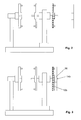
- each first rotary body 10a, 10b carries a plurality of pneumatic suckers 32, which serve as holding elements.
- this pneumatic sucker 32 will be later with reference to the FIGS. 17 and 18 received.
- These pneumatic suckers 32 extend in a longitudinal direction parallel to the shafts 14a, 14b.
- the device further has a movable arm 28, which has a rotatable about the winding axis S second rotary body 20. This can be offset by a drive motor 26 in a corresponding rotational movement.
- This second rotary body has, just like the two first rotary bodies 10a, 10b, a thickened hub region 22 and pneumatic suction pads 32 serving as holding elements. Each rotary body preferably carries in symmetrical distribution four to eight such pneumatic suction pads 32, wherein in the FIG. 1 only two are shown.
- the second rotary body 20 has no waves but a recess 23 which is coaxial with the winding axis.
- the movable arm 28 (and thus also the second rotary body 20) is movable parallel to the winding axis S from a first to a second end position, wherein in FIG. 1 the second end position is shown, in which the second rotary body 20 has its maximum distance from the first rotary bodies.
- the drive mechanism for the movable arm 28 is in FIG. 1 not shown.
- FIG. 1 schematically shown a coil 50. This consists of a coil core 52 and two circular disk-shaped side walls 54 held on the coil core 52.
- the material of the coil 50 is, as already mentioned, cardboard.
- FIGS. 17 to 19 show schematic sectional views of a pneumatic cleaner 32, as it is preferably used in the present invention.
- the pneumatic sucker 32 is made of an elastic material such as rubber or silicone.
- the pneumatic sucker 32 extends along an axial direction (this is parallel to the winding axis during winding; the pneumatic suckers of the second rotating body always extend parallel to the winding axis) from a connection side 34 to a suction side 36.
- the middle section 38 extending therebetween formed in the form of a bellows.
- the suction side 36 is completely open or has at least one hole.
- the connection side 34 is fixedly connected to the respective rotary body.
- the suction side 36 in contact with a substantially planar object (this is the outer surface of a side wall 54 of a coil 50 in the inventive device) and the connection side 34 is connected to a suction pump, it is due to the fact that the hole the suction side 36 is closed by the object, within the pneumatic suction 32 to a negative pressure, whereby this exerts a force in the direction F on the substantially planar object. If the corresponding object can move in this direction, the middle section 38 contracts and pulls the object in the direction F. The suction side 36 thus forms the holding side of the pneumatic suction device.
- FIG. 1 the pneumatic suckers 32 are shown in a state in which they have their maximum length, in which they extend slightly beyond the thickened hub regions 12a, 12b, 22 in the axial direction.
- FIG. 2 shows the same as that FIG. 1 namely a state in which no coil 50 is arranged on a rotary body.
- This state can occur, for example, when the punching machine that delivers the strip-shaped material that is to be wound up on reels 50 starts fresh after a production interruption.
- at least one coil is always arranged on a first rotary body, as will be seen later.
- a coil 50 is attached to the shaft 14b of the first rotary body 10b, which faces away from the second rotary body 20. This is in FIG. 3 shown.
- the vertical arm rotates by 180 ° and brings the first rotary body 10b in the FIG. 4 shown position in which it is opposite to the second rotary body 20.
- the two shafts 14a, 14b are of course not coaxial with the winding axis, after reaching the in FIG. 4 However, this condition is fulfilled again.
- the second rotary body 20 moved by means of its movable arm 28 in its first end position, in which the Spool core 52 is clamped between the hub portions 12b and 22 is held and all pneumatic suction pads 32 are lightly pressed against the side walls 54 of the held between the rotating bodies 10b, 20 coil 50.
- the shaft 14b extends into the recess 23. This makes it possible to use coils of different thickness.
- the pneumatic suckers are now operated (ie supplied with negative pressure), so that they are trapped on the outer sides of the side walls 54 and pull them outwards, so that the in FIG. 6 shown state occurs.
- the curvature of the side walls 54 to the outside is exaggerated strong here.
- the first rotary body 10b and the second rotary body 20 are now rotated about the winding axis, wherein in the illustrated embodiment, the two drive motors 16b and 26 are used, which are synchronized to each other.
- the two drive motors 16b and 26 are used, which are synchronized to each other.
- the band-shaped material is now wound on the spool core 52 (see FIGS. 7 and 8th ), so that a winding 60 is formed.
- a new spool 50 ' is provided and mounted on the shaft 14a of the outwardly facing first rotating body 10a. If the coil 50 is full, the drive motors 16b and 26 are stopped and the second rotary body 20 is moved back to its second end position, so that the in FIG. 9 shown condition prevails.
- the vertical arm 18 is now again pivoted by 180 ° about its vertical pivot axis S, so that the empty coil 50 'is now in a state corresponding to FIG. 4 located. It begins now a new cycle.
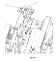
- FIGS. 12 to 15 Now, a second embodiment of the invention will be described.
- the basic structure is identical to the same described embodiment; Similar components are therefore provided with the same reference numerals as in the first embodiment.
- the drive unit for the movable arm 28, namely in the form of a screw 29a and a motor 29b recognize.
- the Indian FIG. 12 shown state corresponds to the state of FIG. 5 but no coil is shown.
- the main difference from the first exemplary embodiment is that the surfaces of the rotary bodies 10a, b and 20 facing the coils are completely flat here, ie have no thickened hub areas. This ensures that the side walls of the coils 54 are brought into a completely flat and mutually parallel position.
- the rotary bodies 10a, b and 20 have openings 30 through which the pneumatic suckers 32 protrude. This one can in particular the FIG. 15 remove.
- a coil is now located between a first rotary body 10a or 10b and the second rotary body 20 and the pneumatic suckers 32 are activated (ie subjected to negative pressure), they suck the side walls 54 of a coil until they are in each case flat against the inward facing Abut surfaces of the rotating body.
- FIG. 16 shows again the device of the second embodiment, which is mounted on a table, which additionally carries a robot 40 for bobbin change.
- the winding axis runs in each case horizontally. However, this is not mandatory: There are also other embodiments possible, in particular those with vertically extending winding axis.
Landscapes
- Replacement Of Web Rolls (AREA)
- Winding Of Webs (AREA)
- Manipulator (AREA)
Applications Claiming Priority (1)
| Application Number | Priority Date | Filing Date | Title |
|---|---|---|---|
| DE102012016479.3A DE102012016479B4 (de) | 2012-08-17 | 2012-08-17 | Vorrichtung zum Aufwickeln von bandförmigem Material auf Spulen |
Publications (3)
| Publication Number | Publication Date |
|---|---|
| EP2698332A2 true EP2698332A2 (fr) | 2014-02-19 |
| EP2698332A3 EP2698332A3 (fr) | 2017-09-27 |
| EP2698332B1 EP2698332B1 (fr) | 2018-09-12 |
Family
ID=48874752
Family Applications (1)
| Application Number | Title | Priority Date | Filing Date |
|---|---|---|---|
| EP13003624.7A Active EP2698332B1 (fr) | 2012-08-17 | 2013-07-18 | Dispositif d'enroulement d'un matériau en forme de bande sur des bobines |
Country Status (4)
| Country | Link |
|---|---|
| US (1) | US9517909B2 (fr) |
| EP (1) | EP2698332B1 (fr) |
| DE (1) | DE102012016479B4 (fr) |
| ES (1) | ES2694751T3 (fr) |
Families Citing this family (6)
| Publication number | Priority date | Publication date | Assignee | Title |
|---|---|---|---|---|
| DE102015201180B4 (de) * | 2014-01-23 | 2018-05-30 | Fosber S.P.A. | Abrollvorrichtung zum Abrollen von Spulen eines bahnförmigen Materials |
| DE102014222756A1 (de) | 2014-11-07 | 2016-05-12 | Leicht Stanzautomation Gmbh | Vorrichtung zum Aufwickeln von bandförmigem Material |
| DE112021001834T5 (de) * | 2020-03-25 | 2023-01-12 | Panasonic Intellectual Property Management Co., Ltd. | Trägerbandverarbeitungsvorrichtung und Trägerbandverarbeitungsverfahren |
| CN112897134A (zh) * | 2021-02-23 | 2021-06-04 | 重庆鼎盛印务股份有限公司 | 薄膜自动收卷装置 |
| CN115072447A (zh) * | 2021-03-11 | 2022-09-20 | 泰科电子(上海)有限公司 | 料带处理系统 |
| US12195289B2 (en) * | 2022-06-24 | 2025-01-14 | Te Connectivity Solutions Gmbh | Reel handling machine |
Family Cites Families (17)
| Publication number | Priority date | Publication date | Assignee | Title |
|---|---|---|---|---|
| USRE23450E (en) * | 1952-01-15 | Sheetsxsheet i | ||
| FR466777A (fr) * | 1913-12-23 | 1914-05-23 | Francon Et Pleynet Soc | Appareil universel pour le pliage des dentelles, rubans, lacets, etc. |
| US2327906A (en) * | 1941-04-02 | 1943-08-24 | Streine Tool And Mfg Company | Strip coil handling |
| US2332576A (en) * | 1941-10-30 | 1943-10-26 | Mesta Machine Co | Reel mechanism |
| US2567670A (en) * | 1947-06-14 | 1951-09-11 | Mesta Machine Co | Feed reel |
| US3478974A (en) * | 1968-01-02 | 1969-11-18 | Fmc Corp | Roll stand for converting equipment |
| DE1933926A1 (de) * | 1969-07-04 | 1971-01-14 | Georg Heckel Gmbh | Vorrichtung zum Aufwickeln von strangfoermigem Gut auf Spulen grosser Abmessungen |
| GB1514782A (en) * | 1975-09-03 | 1978-06-21 | Shakespeare K | Paper-winding units |
| JPS60186271A (ja) * | 1984-02-15 | 1985-09-21 | 日本たばこ産業株式会社 | リ−ル供給装置におけるストツカ− |
| DE3432753A1 (de) * | 1984-09-06 | 1986-03-13 | Benninger Ag, Uzwil | Wickelmaschine zum aufwickeln und/oder abwickeln bahnfoermig gefuehrten gutes |
| DE8908818U1 (de) * | 1989-07-20 | 1989-09-07 | Bauer, Heinz, 7531 Neulingen | Zuführungseinrichtung für Formbänder zu einer Aufwickelvorrichtung |
| IT1253272B (it) * | 1991-10-10 | 1995-07-14 | Gd Spa | Dispositivo per la sostituzione di bobine di materiale in nastro in una macchina operatrice |
| US6015114A (en) * | 1997-03-27 | 2000-01-18 | Axis Usa, Inc. | Method and apparatus for expeditiously providing a reel of insulation material to an insulating machine |
| DE10025848A1 (de) * | 2000-05-25 | 2001-11-29 | Topack Verpacktech Gmbh | Vorrichtung zum Handhaben von Bobinen |
| DE20112879U1 (de) * | 2001-08-02 | 2002-02-21 | Weger, Manfred, 87437 Kempten | Kombi-Kurbelgerät |
| US7281677B2 (en) * | 2005-01-10 | 2007-10-16 | National Carpet Equipment, Inc. | Strip winding machine |
| JP5665353B2 (ja) * | 2010-04-23 | 2015-02-04 | キヤノン株式会社 | 支持装置、プリント装置、支持方法、および装填方法 |
-
2012
- 2012-08-17 DE DE102012016479.3A patent/DE102012016479B4/de not_active Expired - Fee Related
-
2013
- 2013-07-18 ES ES13003624.7T patent/ES2694751T3/es active Active
- 2013-07-18 EP EP13003624.7A patent/EP2698332B1/fr active Active
- 2013-08-14 US US13/966,810 patent/US9517909B2/en active Active
Non-Patent Citations (1)
| Title |
|---|
| None |
Also Published As
| Publication number | Publication date |
|---|---|
| EP2698332B1 (fr) | 2018-09-12 |
| EP2698332A3 (fr) | 2017-09-27 |
| DE102012016479A1 (de) | 2014-02-20 |
| DE102012016479B4 (de) | 2016-11-03 |
| US20140048642A1 (en) | 2014-02-20 |
| ES2694751T3 (es) | 2018-12-27 |
| US9517909B2 (en) | 2016-12-13 |
Similar Documents
| Publication | Publication Date | Title |
|---|---|---|
| EP2698332B1 (fr) | Dispositif d'enroulement d'un matériau en forme de bande sur des bobines | |
| DE10035894B4 (de) | Wickeleinrichtung für Bandmaterial | |
| DE4142256A1 (de) | Verfahren und vorrichtung zum wechseln von spulen in einer verarbeitungsmaschine von bandmaterial | |
| DE1805389A1 (de) | Bandaufwickelvorrichtung | |
| DE112016001518T5 (de) | Rotor und Pumpenvorrichtung | |
| DE102022105161A1 (de) | Materialstreifen-Verarbeitungssystem | |
| DE102014019506A1 (de) | Vorrichtung und Verfahren zur Herstellung von Fadenbündeln | |
| EP0030402A1 (fr) | Appareil pour l'enroulage de bandes coupées | |
| DE2410439A1 (de) | Ausrichtmaschine fuer metallprofile | |
| DE102015201180B4 (de) | Abrollvorrichtung zum Abrollen von Spulen eines bahnförmigen Materials | |
| DE102013000808B4 (de) | Vorrichtung zum Aufwickeln von bandförmigem Material | |
| EP3641983B1 (fr) | Plateau rotatif comprenant un entraînement optimisé en force | |
| EP2142458B1 (fr) | Dispositif de paraffinage pour un poste de travail d'une machine textile fabriquant des bobines croisées | |
| EP3643458A2 (fr) | Dispositif de préhension permettant d'appréhender des feuilles métalliques | |
| DE4119290A1 (de) | Vorrichtung zum spulenwechsel in einer bandmaterial verarbeitenden maschine | |
| DE202011107220U1 (de) | Drahtfördervorrichtung | |
| DE102008056660A1 (de) | Etikettiervorrichtung | |
| DE102011108647A1 (de) | Maschine zum Abtragen von Material am Umfang eines Schlauches | |
| DE2906177A1 (de) | Schneideinrichtung fuer schlauchfoermige werkstuecke | |
| EP3261967B1 (fr) | Dispositif et procédé de manipulation d'un écheveau de fils enroulés | |
| DE69409266T2 (de) | Vorrichtung zum Greifen und Transportieren eines auf einem Lagerbock horizontal angeordneten Zylinders | |
| EP2998258A1 (fr) | Dispositif d'enroulement de feuille pour une machine d'emballage | |
| DE102014002029A1 (de) | Vorrichtung zum kontinuierlichen Aufspulen eines Fadens | |
| DE2624168C3 (de) | Verfahren und Vorrichtung zum Fangen eines Fadens beim Spulenwechsel | |
| DE2421088C3 (de) | Einrichtung zum Ausrichten von Statorblechen für elektrische Maschinen |
Legal Events
| Date | Code | Title | Description |
|---|---|---|---|
| AK | Designated contracting states |
Kind code of ref document: A2 Designated state(s): AL AT BE BG CH CY CZ DE DK EE ES FI FR GB GR HR HU IE IS IT LI LT LU LV MC MK MT NL NO PL PT RO RS SE SI SK SM TR |
|
| AX | Request for extension of the european patent |
Extension state: BA ME |
|
| PUAI | Public reference made under article 153(3) epc to a published international application that has entered the european phase |
Free format text: ORIGINAL CODE: 0009012 |
|
| PUAL | Search report despatched |
Free format text: ORIGINAL CODE: 0009013 |
|
| AK | Designated contracting states |
Kind code of ref document: A3 Designated state(s): AL AT BE BG CH CY CZ DE DK EE ES FI FR GB GR HR HU IE IS IT LI LT LU LV MC MK MT NL NO PL PT RO RS SE SI SK SM TR |
|
| AX | Request for extension of the european patent |
Extension state: BA ME |
|
| RIC1 | Information provided on ipc code assigned before grant |
Ipc: B65H 19/22 20060101AFI20170818BHEP Ipc: B65H 18/10 20060101ALI20170818BHEP |
|
| RIC1 | Information provided on ipc code assigned before grant |
Ipc: B65H 19/22 20060101AFI20170906BHEP Ipc: B65H 18/10 20060101ALI20170906BHEP |
|
| STAA | Information on the status of an ep patent application or granted ep patent |
Free format text: STATUS: REQUEST FOR EXAMINATION WAS MADE |
|
| 17P | Request for examination filed |
Effective date: 20171012 |
|
| RBV | Designated contracting states (corrected) |
Designated state(s): AL AT BE BG CH CY CZ DE DK EE ES FI FR GB GR HR HU IE IS IT LI LT LU LV MC MK MT NL NO PL PT RO RS SE SI SK SM TR |
|
| GRAP | Despatch of communication of intention to grant a patent |
Free format text: ORIGINAL CODE: EPIDOSNIGR1 |
|
| STAA | Information on the status of an ep patent application or granted ep patent |
Free format text: STATUS: GRANT OF PATENT IS INTENDED |
|
| INTG | Intention to grant announced |
Effective date: 20180410 |
|
| GRAS | Grant fee paid |
Free format text: ORIGINAL CODE: EPIDOSNIGR3 |
|
| GRAA | (expected) grant |
Free format text: ORIGINAL CODE: 0009210 |
|
| STAA | Information on the status of an ep patent application or granted ep patent |
Free format text: STATUS: THE PATENT HAS BEEN GRANTED |
|
| AK | Designated contracting states |
Kind code of ref document: B1 Designated state(s): AL AT BE BG CH CY CZ DE DK EE ES FI FR GB GR HR HU IE IS IT LI LT LU LV MC MK MT NL NO PL PT RO RS SE SI SK SM TR |
|
| REG | Reference to a national code |
Ref country code: GB Ref legal event code: FG4D Free format text: NOT ENGLISH |
|
| REG | Reference to a national code |
Ref country code: CH Ref legal event code: EP |
|
| REG | Reference to a national code |
Ref country code: IE Ref legal event code: FG4D Free format text: LANGUAGE OF EP DOCUMENT: GERMAN |
|
| REG | Reference to a national code |
Ref country code: DE Ref legal event code: R096 Ref document number: 502013011041 Country of ref document: DE |
|
| REG | Reference to a national code |
Ref country code: AT Ref legal event code: REF Ref document number: 1040296 Country of ref document: AT Kind code of ref document: T Effective date: 20181015 |
|
| REG | Reference to a national code |
Ref country code: NL Ref legal event code: MP Effective date: 20180912 |
|
| REG | Reference to a national code |
Ref country code: LT Ref legal event code: MG4D |
|
| PG25 | Lapsed in a contracting state [announced via postgrant information from national office to epo] |
Ref country code: BG Free format text: LAPSE BECAUSE OF FAILURE TO SUBMIT A TRANSLATION OF THE DESCRIPTION OR TO PAY THE FEE WITHIN THE PRESCRIBED TIME-LIMIT Effective date: 20181212 Ref country code: LT Free format text: LAPSE BECAUSE OF FAILURE TO SUBMIT A TRANSLATION OF THE DESCRIPTION OR TO PAY THE FEE WITHIN THE PRESCRIBED TIME-LIMIT Effective date: 20180912 Ref country code: NO Free format text: LAPSE BECAUSE OF FAILURE TO SUBMIT A TRANSLATION OF THE DESCRIPTION OR TO PAY THE FEE WITHIN THE PRESCRIBED TIME-LIMIT Effective date: 20181212 Ref country code: SE Free format text: LAPSE BECAUSE OF FAILURE TO SUBMIT A TRANSLATION OF THE DESCRIPTION OR TO PAY THE FEE WITHIN THE PRESCRIBED TIME-LIMIT Effective date: 20180912 Ref country code: GR Free format text: LAPSE BECAUSE OF FAILURE TO SUBMIT A TRANSLATION OF THE DESCRIPTION OR TO PAY THE FEE WITHIN THE PRESCRIBED TIME-LIMIT Effective date: 20181213 Ref country code: RS Free format text: LAPSE BECAUSE OF FAILURE TO SUBMIT A TRANSLATION OF THE DESCRIPTION OR TO PAY THE FEE WITHIN THE PRESCRIBED TIME-LIMIT Effective date: 20180912 Ref country code: FI Free format text: LAPSE BECAUSE OF FAILURE TO SUBMIT A TRANSLATION OF THE DESCRIPTION OR TO PAY THE FEE WITHIN THE PRESCRIBED TIME-LIMIT Effective date: 20180912 |
|
| PG25 | Lapsed in a contracting state [announced via postgrant information from national office to epo] |
Ref country code: AL Free format text: LAPSE BECAUSE OF FAILURE TO SUBMIT A TRANSLATION OF THE DESCRIPTION OR TO PAY THE FEE WITHIN THE PRESCRIBED TIME-LIMIT Effective date: 20180912 Ref country code: LV Free format text: LAPSE BECAUSE OF FAILURE TO SUBMIT A TRANSLATION OF THE DESCRIPTION OR TO PAY THE FEE WITHIN THE PRESCRIBED TIME-LIMIT Effective date: 20180912 Ref country code: HR Free format text: LAPSE BECAUSE OF FAILURE TO SUBMIT A TRANSLATION OF THE DESCRIPTION OR TO PAY THE FEE WITHIN THE PRESCRIBED TIME-LIMIT Effective date: 20180912 |
|
| PG25 | Lapsed in a contracting state [announced via postgrant information from national office to epo] |
Ref country code: PL Free format text: LAPSE BECAUSE OF FAILURE TO SUBMIT A TRANSLATION OF THE DESCRIPTION OR TO PAY THE FEE WITHIN THE PRESCRIBED TIME-LIMIT Effective date: 20180912 Ref country code: EE Free format text: LAPSE BECAUSE OF FAILURE TO SUBMIT A TRANSLATION OF THE DESCRIPTION OR TO PAY THE FEE WITHIN THE PRESCRIBED TIME-LIMIT Effective date: 20180912 Ref country code: NL Free format text: LAPSE BECAUSE OF FAILURE TO SUBMIT A TRANSLATION OF THE DESCRIPTION OR TO PAY THE FEE WITHIN THE PRESCRIBED TIME-LIMIT Effective date: 20180912 Ref country code: IS Free format text: LAPSE BECAUSE OF FAILURE TO SUBMIT A TRANSLATION OF THE DESCRIPTION OR TO PAY THE FEE WITHIN THE PRESCRIBED TIME-LIMIT Effective date: 20190112 Ref country code: RO Free format text: LAPSE BECAUSE OF FAILURE TO SUBMIT A TRANSLATION OF THE DESCRIPTION OR TO PAY THE FEE WITHIN THE PRESCRIBED TIME-LIMIT Effective date: 20180912 |
|
| PG25 | Lapsed in a contracting state [announced via postgrant information from national office to epo] |
Ref country code: SK Free format text: LAPSE BECAUSE OF FAILURE TO SUBMIT A TRANSLATION OF THE DESCRIPTION OR TO PAY THE FEE WITHIN THE PRESCRIBED TIME-LIMIT Effective date: 20180912 Ref country code: PT Free format text: LAPSE BECAUSE OF FAILURE TO SUBMIT A TRANSLATION OF THE DESCRIPTION OR TO PAY THE FEE WITHIN THE PRESCRIBED TIME-LIMIT Effective date: 20190112 Ref country code: SM Free format text: LAPSE BECAUSE OF FAILURE TO SUBMIT A TRANSLATION OF THE DESCRIPTION OR TO PAY THE FEE WITHIN THE PRESCRIBED TIME-LIMIT Effective date: 20180912 |
|
| REG | Reference to a national code |
Ref country code: DE Ref legal event code: R097 Ref document number: 502013011041 Country of ref document: DE |
|
| PLBE | No opposition filed within time limit |
Free format text: ORIGINAL CODE: 0009261 |
|
| STAA | Information on the status of an ep patent application or granted ep patent |
Free format text: STATUS: NO OPPOSITION FILED WITHIN TIME LIMIT |
|
| PG25 | Lapsed in a contracting state [announced via postgrant information from national office to epo] |
Ref country code: DK Free format text: LAPSE BECAUSE OF FAILURE TO SUBMIT A TRANSLATION OF THE DESCRIPTION OR TO PAY THE FEE WITHIN THE PRESCRIBED TIME-LIMIT Effective date: 20180912 |
|
| 26N | No opposition filed |
Effective date: 20190613 |
|
| PG25 | Lapsed in a contracting state [announced via postgrant information from national office to epo] |
Ref country code: SI Free format text: LAPSE BECAUSE OF FAILURE TO SUBMIT A TRANSLATION OF THE DESCRIPTION OR TO PAY THE FEE WITHIN THE PRESCRIBED TIME-LIMIT Effective date: 20180912 |
|
| PG25 | Lapsed in a contracting state [announced via postgrant information from national office to epo] |
Ref country code: MC Free format text: LAPSE BECAUSE OF FAILURE TO SUBMIT A TRANSLATION OF THE DESCRIPTION OR TO PAY THE FEE WITHIN THE PRESCRIBED TIME-LIMIT Effective date: 20180912 |
|
| GBPC | Gb: european patent ceased through non-payment of renewal fee |
Effective date: 20190718 |
|
| PG25 | Lapsed in a contracting state [announced via postgrant information from national office to epo] |
Ref country code: TR Free format text: LAPSE BECAUSE OF FAILURE TO SUBMIT A TRANSLATION OF THE DESCRIPTION OR TO PAY THE FEE WITHIN THE PRESCRIBED TIME-LIMIT Effective date: 20180912 |
|
| PG25 | Lapsed in a contracting state [announced via postgrant information from national office to epo] |
Ref country code: GB Free format text: LAPSE BECAUSE OF NON-PAYMENT OF DUE FEES Effective date: 20190718 |
|
| PG25 | Lapsed in a contracting state [announced via postgrant information from national office to epo] |
Ref country code: LU Free format text: LAPSE BECAUSE OF NON-PAYMENT OF DUE FEES Effective date: 20190718 |
|
| PG25 | Lapsed in a contracting state [announced via postgrant information from national office to epo] |
Ref country code: IE Free format text: LAPSE BECAUSE OF NON-PAYMENT OF DUE FEES Effective date: 20190718 |
|
| PG25 | Lapsed in a contracting state [announced via postgrant information from national office to epo] |
Ref country code: CY Free format text: LAPSE BECAUSE OF FAILURE TO SUBMIT A TRANSLATION OF THE DESCRIPTION OR TO PAY THE FEE WITHIN THE PRESCRIBED TIME-LIMIT Effective date: 20180912 |
|
| PG25 | Lapsed in a contracting state [announced via postgrant information from national office to epo] |
Ref country code: MT Free format text: LAPSE BECAUSE OF FAILURE TO SUBMIT A TRANSLATION OF THE DESCRIPTION OR TO PAY THE FEE WITHIN THE PRESCRIBED TIME-LIMIT Effective date: 20180912 Ref country code: HU Free format text: LAPSE BECAUSE OF FAILURE TO SUBMIT A TRANSLATION OF THE DESCRIPTION OR TO PAY THE FEE WITHIN THE PRESCRIBED TIME-LIMIT; INVALID AB INITIO Effective date: 20130718 |
|
| PG25 | Lapsed in a contracting state [announced via postgrant information from national office to epo] |
Ref country code: MK Free format text: LAPSE BECAUSE OF FAILURE TO SUBMIT A TRANSLATION OF THE DESCRIPTION OR TO PAY THE FEE WITHIN THE PRESCRIBED TIME-LIMIT Effective date: 20180912 |
|
| P01 | Opt-out of the competence of the unified patent court (upc) registered |
Effective date: 20230523 |
|
| PGFP | Annual fee paid to national office [announced via postgrant information from national office to epo] |
Ref country code: ES Payment date: 20250819 Year of fee payment: 13 |
|
| PGFP | Annual fee paid to national office [announced via postgrant information from national office to epo] |
Ref country code: DE Payment date: 20250917 Year of fee payment: 13 |
|
| PGFP | Annual fee paid to national office [announced via postgrant information from national office to epo] |
Ref country code: IT Payment date: 20250731 Year of fee payment: 13 |
|
| PGFP | Annual fee paid to national office [announced via postgrant information from national office to epo] |
Ref country code: BE Payment date: 20250722 Year of fee payment: 13 |
|
| PGFP | Annual fee paid to national office [announced via postgrant information from national office to epo] |
Ref country code: FR Payment date: 20250723 Year of fee payment: 13 Ref country code: AT Payment date: 20250721 Year of fee payment: 13 |
|
| PGFP | Annual fee paid to national office [announced via postgrant information from national office to epo] |
Ref country code: CH Payment date: 20250801 Year of fee payment: 13 |
|
| PGFP | Annual fee paid to national office [announced via postgrant information from national office to epo] |
Ref country code: CZ Payment date: 20250708 Year of fee payment: 13 |