EP2698472B1 - Strassenbaumaschine - Google Patents
Strassenbaumaschine Download PDFInfo
- Publication number
- EP2698472B1 EP2698472B1 EP13003274.1A EP13003274A EP2698472B1 EP 2698472 B1 EP2698472 B1 EP 2698472B1 EP 13003274 A EP13003274 A EP 13003274A EP 2698472 B1 EP2698472 B1 EP 2698472B1
- Authority
- EP
- European Patent Office
- Prior art keywords
- scraper
- profile
- retaining apparatus
- support rail
- complementary
- Prior art date
- Legal status (The legal status is an assumption and is not a legal conclusion. Google has not performed a legal analysis and makes no representation as to the accuracy of the status listed.)
- Active
Links
Images



Classifications
-
- E—FIXED CONSTRUCTIONS
- E01—CONSTRUCTION OF ROADS, RAILWAYS, OR BRIDGES
- E01C—CONSTRUCTION OF, OR SURFACES FOR, ROADS, SPORTS GROUNDS, OR THE LIKE; MACHINES OR AUXILIARY TOOLS FOR CONSTRUCTION OR REPAIR
- E01C19/00—Machines, tools or auxiliary devices for preparing or distributing paving materials, for working the placed materials, or for forming, consolidating, or finishing the paving
- E01C19/22—Machines, tools or auxiliary devices for preparing or distributing paving materials, for working the placed materials, or for forming, consolidating, or finishing the paving for consolidating or finishing laid-down unset materials
- E01C19/23—Rollers therefor; Such rollers usable also for compacting soil
- E01C19/238—Wetting, cleaning or heating rolling elements, e.g. oiling, wiping, scraping
Definitions
- the invention relates to a scraper for a bandage of a road roller with a voltage applied to the bandage scraper bar, which is held on a support rail, and with a holding device for the mounting rail.
- the invention further relates to a road roller with such a scraper.
- the invention is based on the object to provide a scraper of the type mentioned, which can be mounted in a simple manner.
- a T-profile or a dovetail profile is formed and as a counterpart to the T-profile or dovetail profile complementary Anschraubelement is present.
- the T-profile or dovetail profile may be arranged on the side of the scraper or on the side of the road roller.
- T-profiles and dovetail profiles are known. They are used with counterparts having a groove-complementary shape, such as T-nut, T-slot, T-slot, etc., to provide a connection between two parts.
- the invention has the advantage that the attachment points along the T-profile or the dovetail profile are individually adjustable by the fact that the profile-carrying part and the counterpart are moved relative to each other.
- the attachment of the scraper to different machines are adapted.
- the total assembly time of the machine is shortened. If an exchange of the scraper is required, this is possible in a simple manner.
- a preferred embodiment of the invention is that the T-profile or dovetail profile carries additional attachments. It is expedient that the mounting rail has the T-profile or dovetail profile. Alternatively, it may be advantageous to attach the T-profile or dovetail profile to the road roller.
- attachments e.g. a handle, a protective cover, a spray nozzle, a climbing aid, e.g. a tread, and / or to arrange a mirror.
- These elements can thus be placed in the immediate vicinity of the bandage, with a great freedom with respect to the installation site. They can be used, for example, to further clean the bandage, to shield the bandage, and to closely observe the bandage and area before the bandage.
- Fig. 1 illustrates a designed as a road roller 1 self-propelled construction machine with a front end 2 and a rear end 3, which are connected to each other via a pendulum / articulated joint.
- a front drum 4 and the rear carriage 3 At the front of the car 2, a front drum 4 and the rear carriage 3, a rear drum 5 is arranged.
- the two bandages 4, 5 are mounted on vertical side supports 6, 7 on the front end 2 and rear end 3, which are held on the frame-side side supports 8 and 9 respectively.
- On the front of the car 2 is also a driver's cab 10th
- a scraper 12 is arranged over the entire width of the bandage 4, which abuts against the bandage surface, and which can be folded down as needed.
- two handles 13 are arranged at its two ends.
- the scraper 12 is fixed to a frame-side part 14 of the road roller 1 by means of two spaced support devices 15.
- a baffle plate 29 are arranged at the two front ends of the scraper 12, which prevent splashing water side can escape from the gap between the scraper 12 and the bandage surface, which is sprayed by spray nozzles 30 to prevent adhesion to the front bandage 4.
- the spray nozzles 30 are distributed in the illustrated example across the width of the front bandage 4 and attached to the frame-side member 14.
- Fig. 2 illustrates a partial view of the scraper 12 from a direction according to arrow 11 in Fig. 1 , on the bandage 4 ( Fig. 1 ) facing away.
- the scraper 12 has a support rail 17 and a scraper strip 16 made of rubber-elastic material, the free end is in operative position of the scraper 12 with the bandage 4 in contact. In the rest position, when the scraper 12 is folded upwards, the scraper blade 16 is out of contact with the drum 4. The scraper blade 16 is held over its entire length in the support rail 17, which is formed as an extruded profile.
- the support devices 15 are held, with their positions along the support rail 17 are freely selectable and variably variable.
- the support rail 17 is used for releasably supporting add-on elements, with which different auxiliary functions when operating and operating the road roller 1 can be performed.
- the attachment elements are the handles 13 and the baffles 29.
- the mounting rail profile has a receiving slot 18 of constant width on an end face, in which the scraper blade 16 is inserted. With bolts 19, the two legs of the receiving slot 18 are pressed together, so that the scraper blade 16 is held by press fit.
- the DIN rail also has on the opposite end face of the support rail 17 over its entire length a T-slot 20.
- the T-slot 20 serves as a rail, in which as complementary complementary Anschraubemia for the support device 15 and the attachments, here handles 13 and baffles 29, are held, with their positions along the T-slot 20 are freely selectable and variable as needed.
- the Anschraubemia for the support device 15 and the add-on elements are formed as sliding blocks 21, 22, 23, which are inserted into the T-slot 20, and with which the support device 15 and the handles 13 and the baffles 29 in the T-slot 20th are tense.
- the cooperating with the sliding blocks 21, 22, 23 bolts are designated 31, 32, 33, 33 '.
- the support device 15 has according to Fig. 2 two bearing blocks 15a, 15b on a base plate 34, wherein the bearing blocks 15a, 15b carry a hinge 23 to allow the folding of the scraper 12.
- the hinge 23 is in communication with a frame-side arm 35.
- the base plate 34 is seated on the support rail 17 via the T-slot 20 and the sliding block 23.
- the associated bolt 33 is screwed through a bore (not shown) in the base plate 34 in the sliding block 23.
- Base plate 34, bolt 33 and sliding block 23 form a complementary to the T-slot 20 Abstreiferhalterung, which is supplemented in the example shown by the other bolts 33 'and an associated nut (not shown).
- a complementary to the T-slot 20 handle mount is formed by the bolts 32, the associated sliding blocks 22 (only one sliding block is visible) and by a further base plate 36 corresponding to the base plate 34 of the Abstreiferhalterung.
- a baffle plate holder is formed by the bolts 31, the associated sliding blocks 21 (only one sliding block is visible) and by a third base plate 37 corresponding to the base plate 34 of the Abstreiferhalterung.
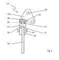
- the Fig. 3 shows a cross section through the scraper 12 according to Fig. 2 along a section line between the handle 13 and the support device 1 with a view of the support device 15th
- the support rail 17 has a single contact surface 24 for the scraper blade 16, and the scraper blade 16 is pressed onto this contact surface 24 via a separate rail 25.
- the scraper 12 "according to Fig. 5 is provided with a DIN rail profile, in contrast to the execution of Fig. 2 and 3 a receiving slot 18 'with an L-profile 26 has.
- the relevant edge of the scraper strip 16' also provided with an L-profile 27, so that the scraper blade 16 'is held by positive engagement.
Landscapes
- Engineering & Computer Science (AREA)
- Architecture (AREA)
- Civil Engineering (AREA)
- Structural Engineering (AREA)
- Road Paving Machines (AREA)
- Machines For Laying And Maintaining Railways (AREA)
Description
- Die Erfindung betrifft einen Abstreifer für eine Bandage einer Straßenwalze mit einer an der Bandage anliegenden Abstreiferleiste, die an einer Tragschiene gehalten ist, und mit einer Haltevorrichtung für die Tragschiene. Die Erfindung betrifft ferner eine Straßenwalze mit einem derartigen Abstreifer.
- Straßenwalzen zur Herstellung von Verkehrswegen sind allgemein bekannt. Um die Anhaftung von Verunreinigungen an einer Bandage zu verhindern, wird über die ganze Breite der Bandage ein Abstreifer angeordnet, welcher auf der Zylinderoberfläche der Bandage anliegt und Anhaftungen ablöst. Derartige Abstreifer sind beispielsweise in
DE 29622280 U1 und inJP H10 86798 A - Der Erfindung liegt die Aufgabe zu Grunde, einen Abstreifer der eingangs genannten Art anzugeben, der auf einfache Weise montiert werden kann.
- Diese Aufgabe wird dadurch gelöst, dass die Haltevorrichtung über die Länge der Tragschiene ein T-Profil oder ein Schwalbenschwanzprofil ausgebildet ist und als Gegenstück ein zum T-Profil bzw. Schwalbenschwanzprofil komplementäres Anschraubelement vorhanden ist. Dabei kann das T-Profil oder Schwalbenschwanzprofil auf Seiten des Abstreifers oder auf Seiten der Straßenwalze angeordnet sein.
- T-Profile und Schwalbenschwanzprofile sind bekannt. Sie werden zusammen mit Gegenstücken eingesetzt, welche eine zur Nut komplementäre Form aufweisen, wie T-Nut-Muttern, T-Nut -Steinen, T-Nut-Schrauben, u.ä., um eine Verbindung zwischen zwei Teilen herzustellen.
- Die Erfindung hat den Vorteil, dass die Befestigungspunkte entlang des T-Profils oder des Schwalbenschwanzprofils individuell einstellbar sind, indem dass das Profil tragende Teil und das Gegenstück relativ zueinander verschoben werden. Damit kann die Befestigung des Abstreifers an verschiedene Maschinen angepasst werden. Außerdem wird die Gesamtmontagezeit der Maschine verkürzt. Ist ein Austausch des Abstreifers erforderlich, ist dies auf einfache Weise möglich.
- Eine bevorzugte Weiterbildung der Erfindung besteht darin, dass das T-Profil bzw. Schwalbenschwanzprofil weitere Anbauelemente trägt. Es ist zweckmäßig, dass die Tragschiene das T-Profil bzw. Schwalbenschwanzprofil aufweist. Alternativ kann es vorteilhaft sein, das T-Profil bzw. Schwalbenschwanzprofil an der Straßenwalze anzubringen.
- Besonders vorteilhaft ist es, als Anbauelemente einen Handgriff, eine Schutzabdeckung, eine Sprühdüse, eine Aufstiegshilfe, z.B. eine Trittstufe, und/ oder einen Spiegel anzuordnen. Diese Elemente können somit in unmittelbarer Nähe der Bandage platziert werden, wobei eine große Freiheit bezüglich des Montageortes besteht. Sie können zum Beispiel zur weiteren Reinigung der Bandage, zur Abschirmung der Bandage und zur genauen Beobachtung der Bandage und des Bereichs vor der Bandage eingesetzt werden.
- Nachfolgend wird die Erfindung anhand von in der Zeichnung dargestellten Ausführungsbeispielen weiter erläutert. Es zeigen schematisch:
- Fig. 1
- eine perspektivische Ansicht einer Straßenwalze;
- Fig. 2
- eine perspektivische Teilansicht eines ersten Abstreifers;
- Fig. 3
- einen Querschnitt durch den Abstreifer von
Fig. 2 ; und - Fig. 4 und 5
- jeweils einen Querschnitt durch einen zweiten und dritten Abstreifer.
-
Fig. 1 veranschaulicht eine als Straßenwalze 1 ausgebildete selbstfahrende Baumaschine mit einem Vorderwagen 2 und einen Hinterwagen 3, die über ein Pendel-/ Knickgelenk miteinander verbunden sind. Am Vorderwagen 2 ist eine vordere Bandage 4 und am Hinterwagen 3 eine hintere Bandage 5 angeordnet. Die beiden Bandagen 4, 5 sind über vertikale seitliche Stützen 6, 7 am Vorderwagen 2 bzw. Hinterwagen 3 gelagert, die an rahmenseitigen seitlichen Trägern 8 bzw. 9 gehalten sind. Auf dem Vorderwagen 2 befindet sich ferner eine Fahrerkabine 10. - Vor der vorderen Bandage 4 ist über die gesamte Breite der Bandage 4 ein Abstreifer 12 angeordnet, welcher an der Bandagenoberfläche anliegt, und welcher bei Bedarf nach oben abgeklappt werden kann. Zu diesem Zweck sind an seinen beiden Enden zwei Handgriffe 13 angeordnet. Der Abstreifer 12 ist an einem rahmenseitigen Teil 14 der Straßenwalze 1 mittels zweier beabstandeter Tragvorrichtungen 15 befestigt. Ferner sind an den beiden stirnseitigen Enden des Abstreifers 12 jeweils ein Prallblech 29 angeordnet, welche verhindern, dass Spritzwasser seitlich aus dem Spalt zwischen dem Abstreifer 12 und der Bandageoberfläche austreten kann, welches von Sprühdüsen 30 zur Verhinderung von Anhaftungen auf die vordere Bandage 4 gesprüht wird. Die Sprühdüsen 30 sind in dem dargestellten Beispiel über die Breite der vorderen Bandage 4 verteilt und am rahmenseitigen Teil 14 befestigt.
-
Fig. 2 veranschaulicht eine Teilansicht des Abstreifers 12 aus einer Richtung gemäß Pfeil 11 inFig. 1 . auf die der Bandage 4 (Fig. 1 ) abgewandten Seite. Der Abstreifer 12 weist eine Tragschiene 17 und eine aus gummielastischem Material hergestellte Abstreiferleiste 16 auf, deren freies Ende in Betriebsstellung des Abstreifers 12 mit der Bandage 4 in Kontakt ist. In Ruhestellung, wenn der Abstreifer 12 nach oben abgeklappt ist, ist die Abstreiferleiste 16 außer Kontakt mit der Bandage 4. Die Abstreiferleiste 16 ist über ihre ganze Länge in der Tragschiene 17 gehalten, die als Strangpressprofil ausgebildet ist. - An der Tragschiene 17 sind die Tragvorrichtungen 15 gehalten, wobei ihre Positionen entlang der Tragschiene 17 frei wählbar und bei variabel veränderbar sind. Außerdem dient die Tragschiene 17 zur lösbaren Halterung von Anbauelementen, mit welchen unterschiedliche Hilfsfunktionen beim Betreiben und Bedienen der Straßenwalze 1 ausgeführt werden können. Im dargestellten Beispiel handelt es sich bei den Anbauelementen um die Handgriffe 13 und die Prallbleche 29.
- Das Tragschienenprofil weist an einer Stirnseite einen Aufnahmeschlitz 18 konstanter Breite auf, in welchen die Abstreiferleiste 16 eingesteckt ist. Mit Schraubbolzen 19 werden die beiden Schenkel des Aufnahmeschlitzes 18 zusammengepresst, so dass die Abstreiferleiste 16 durch Presssitz gehalten ist.
- Das Tragschienenprofil weist ferner an der gegenüberliegenden Stirnseite der Tragschiene 17 über deren gesamte Länge eine T-Nut 20 auf. Die T-Nut 20 dient als Schiene, in welcher als Gegenstücke komplementäre Anschraubelemente für die Tragvorrichtung 15 und die Anbauelemente, hier Handgriffe 13 und Prallbleche 29, gehalten sind, wobei ihre Positionen entlang der T-Nut 20 frei wählbar und bei Bedarf variabel sind.
- Die Anschraubelemente für die Tragvorrichtung 15 und die Anbauelemente sind als Nutensteine 21, 22, 23 ausgebildet, die in die T-Nut 20 eingeschoben sind, und mit welchen die Tragvorrichtung 15 bzw. die Handgriffe 13 und die Prallbleche 29 in der T-Nut 20 verspannt sind. Die mit den Nutensteinen 21, 22, 23 zusammenwirkenden Schraubbolzen sind mit 31, 32, 33, 33' bezeichnet.
- Die Tragvorrichtung 15 weist gemäß
Fig. 2 zwei Lagerböcke 15a, 15b auf einer Grundplatte 34 auf, wobei die Lagerböcke 15a, 15b ein Gelenk 23 tragen, um das Umklappen des Abstreifers 12 zu ermöglichen. Das Gelenk 23 steht mit einem rahmenseitigen Arm 35 in Verbindung. Die Grundplatte 34 sitzt auf der Tragschiene 17 über der T-Nut 20 und dem Nutenstein 23. Der zugehörige Schraubbolzen 33 ist durch eine Bohrung (nicht dargestellt) in der Grundplatte 34 in den Nutenstein 23 geschraubt. Grundplatte 34, Schraubbolzen 33 und Nutenstein 23 bilden eine zur T-Nut 20 komplementäre Abstreiferhalterung, die im dargestellten Beispiel durch den weiteren Schraubbolzen 33' und einen zugehörigen Nutenstein (nicht dargestellt) ergänzt ist. - Eine zur T-Nut 20 komplementäre Handgriffhalterung wird durch die Schraubbolzen 32, die zugehörigen Nutensteine 22 (nur eine Nutenstein ist sichtbar) sowie durch eine weitere Grundplatte 36 entsprechend der Grundplatte 34 der Abstreiferhalterung gebildet.
- Eine Prallblechhalterung wird durch die Schraubbolzen 31, die zugehörigen Nutensteine 21 (nur eine Nutenstein ist sichtbar) sowie durch eine dritte Grundplatte 37 entsprechend der Grundplatte 34 der Abstreiferhalterung gebildet.
- Die
Fig. 3 zeigt einen Querschnitt durch den Abstreifer 12 gemäßFig. 2 entlang einer Schnittlinie zwischen dem Handgriff 13 und der Tragvorrichtung 1 mit Blick auf die Tragvorrichtung 15. - Bei einer zweiten Ausführung des Abstreifers 12' gemäß
Fig. 4 weist die Tragschiene 17 eine einzige Anlagefläche 24 für die Abstreiferleiste 16 auf, und die Abstreiferleiste 16 wird über eine separate Schiene 25 auf diese Anlagefläche 24 gepresst. - Der Abstreifer 12" gemäß
Fig. 5 ist mit einem Tragschienenprofil versehen, das im Unterschied zur Ausführung vonFig. 2 und3 einen Aufnahmeschlitz 18' mit einem L-Profil 26 aufweist. Komplementär zum L-Profil 26 des Aufnahmeschlitzes 18' ist der betreffende Rand der Abstreiferleiste 16' ebenfalls mit einem L-Profil 27 versehen, so dass die Abstreiferleiste 16' durch Formschluss gehalten ist.
Claims (10)
- Abstreifer (12) für eine Bandage (4) einer Straßenwalze mit
einer Abstreiferleiste (16),
einer Tragschiene (17), an welcher die Abstreiferleiste (16) gehalten ist,
einer Haltevorrichtung für die Tragschiene (17), und
einer Tragvorrichtung (15), über welche der Abstreifer an der Straßenwalze befestigt ist, dadurch gekennzeichnet,
dass die Haltevorrichtung über die Länge der Tragschiene (17) als ein T-Profil oder ein Schwalbenschwanzprofil ausgebildet ist und als Gegenstück ein zum T-Profil bzw. Schwalbenschwanzprofil komplementäres Anschraubelement vorhanden ist, und
dass die Tragvorrichtung (15) über das Anschraubelement mit der Haltevorrichtung verspannt ist. - Abstreifer (12) nach Anspruch 1,
dadurch gekennzeichnet,
dass die Tragschiene (17) das T-Profil bzw. Schwalbenschwanzprofil aufweist. - Abstreifer (12) nach Anspruch 1 oder 2,
dadurch gekennzeichnet,
dass die Tragschiene (17) mittels des T-Profils bzw. Schwalbenschwanzprofils mindestens ein weiteres Anbauelement trägt. - Abstreifer (12) nach Anspruch 3,
dadurch gekennzeichnet,
dass ein Anbauelement als Handgriff (13) zum Umklappen der Tragschiene (17) zwischen einer Betriebslage und einer Ruhelage ausgeführt ist, und dass der Handgriff (13) eine zur Haltevorrichtung des Abstreifers (12) komplementäre Handgriffhalterung aufweist, so dass er an der Haltevorrichtung des Abstreifers (12) variabel angebracht werden kann. - Abstreifer (12) nach Anspruch 3 oder 4,
dadurch gekennzeichnet,
dass ein Anbauelement als Sprühdüse zum Besprühen der Bandage (4) ausgeführt ist, und dass die Sprühdüse eine zur Haltevorrichtung des Abstreifers (12) komplementäre Sprühdüsenhalterung aufweist, so dass sie an der Haltevorrichtung des Abstreifers (12) angebracht werden kann. - Abstreifer (12) nach einem der Ansprüche 3 bis 5,
dadurch gekennzeichnet,
dass ein Anbauelement als Prallblech (29) für Spritzwasser ausgeführt ist, und dass das Prallblech (29) eine zur Haltevorrichtung des Abstreifers (12) komplementäre Prallblechhalterung aufweist, so dass es an der Haltevorrichtung des Abstreifers (12) variabel angebracht werden kann. - Abstreifer (12) nach einem der Ansprüche 3 bis 6,
dadurch gekennzeichnet,
dass ein Anbauelement als ein Spiegel ausgeführt ist, und dass der Spiegel eine zur Haltevorrichtung des Abstreifers (12) komplementäre Spiegelhalterung aufweist, so dass er an der Haltevorrichtung des Abstreifers (12) variabel angebracht werden kann. - Straßenwalze mit einem Abstreifer (12) nach einem der vorhergehenden Ansprüche.
- Straßenwalze, nach Anspruch 8,
dadurch gekennzeichnet,
dass das T-Profil oder Schwalbenschwanzprofil an ihrem Rahmen und das Gegenstück am Abstreifer (12) angeordnet sind. - Straßenwalze nach Anspruch 8 oder 9,
dadurch gekennzeichnet,
dass das T-Profil oder Schwalbenschwanzprofil als Halterung für ein Anbauelement ausgebildet ist.
Applications Claiming Priority (1)
| Application Number | Priority Date | Filing Date | Title |
|---|---|---|---|
| DE102012016021.6A DE102012016021A1 (de) | 2012-08-13 | 2012-08-13 | Strassenbaumaschine |
Publications (2)
| Publication Number | Publication Date |
|---|---|
| EP2698472A1 EP2698472A1 (de) | 2014-02-19 |
| EP2698472B1 true EP2698472B1 (de) | 2015-09-16 |
Family
ID=48703116
Family Applications (1)
| Application Number | Title | Priority Date | Filing Date |
|---|---|---|---|
| EP13003274.1A Active EP2698472B1 (de) | 2012-08-13 | 2013-06-27 | Strassenbaumaschine |
Country Status (3)
| Country | Link |
|---|---|
| EP (1) | EP2698472B1 (de) |
| JP (1) | JP2014037769A (de) |
| DE (1) | DE102012016021A1 (de) |
Families Citing this family (3)
| Publication number | Priority date | Publication date | Assignee | Title |
|---|---|---|---|---|
| CN107386067B (zh) * | 2017-08-25 | 2019-04-02 | 浙江路之友工程机械有限公司 | 压路机的刮泥装置 |
| CN109013437A (zh) * | 2018-08-17 | 2018-12-18 | 南京奥新可工程科技有限公司 | 一种市政道路修补用压路机压辊清洁装置 |
| CN112442935A (zh) * | 2019-08-28 | 2021-03-05 | 徐州维尔德科技发展有限公司 | 一种道路平整机械装置 |
Family Cites Families (7)
| Publication number | Priority date | Publication date | Assignee | Title |
|---|---|---|---|---|
| US3675546A (en) * | 1970-10-15 | 1972-07-11 | Arthur A Smith | Free flow water system for asphalt rollers |
| NL181703B (nl) * | 1976-12-03 | 1987-05-18 | Lely Nv C Van Der | Grondbewerkingsmachine. |
| JP3792311B2 (ja) * | 1996-09-19 | 2006-07-05 | 酒井重工業株式会社 | 転圧機械の泥除け装置 |
| DE29622280U1 (de) | 1996-12-21 | 1997-02-20 | Wacker-Werke Gmbh & Co Kg, 85084 Reichertshofen | Vorrichtung zum Reinigen der Bandage einer Walze zur Bodenverdichtung von anhaftenden Verunreinigungen und zum Berieseln der Bandage mit Wasser |
| DE20017901U1 (de) * | 2000-10-19 | 2001-06-21 | Hendlmeier, Konrad, 93107 Thalmassing | Abstreifervorrichtung für rotierende, walzenförmige oder radförmige Körper |
| SE525302C2 (sv) * | 2002-08-23 | 2005-01-25 | Dynapac Compaction Equip Ab | Skrapa för självgående vält |
| WO2012008359A1 (ja) * | 2010-07-14 | 2012-01-19 | 日立建機株式会社 | 転圧車両 |
-
2012
- 2012-08-13 DE DE102012016021.6A patent/DE102012016021A1/de not_active Withdrawn
-
2013
- 2013-06-27 EP EP13003274.1A patent/EP2698472B1/de active Active
- 2013-08-09 JP JP2013166596A patent/JP2014037769A/ja active Pending
Also Published As
| Publication number | Publication date |
|---|---|
| EP2698472A1 (de) | 2014-02-19 |
| DE102012016021A1 (de) | 2014-02-13 |
| JP2014037769A (ja) | 2014-02-27 |
Similar Documents
| Publication | Publication Date | Title |
|---|---|---|
| EP2297020B1 (de) | Fahrzeugkran mit schlauchführung | |
| DE102012018918B4 (de) | Abstreifvorrichtung für Fräswalzen einer Baumaschine und Baumaschine | |
| DE112016003305T5 (de) | Arbeitsmaschine | |
| DE10317470B4 (de) | Sprühfeuchtwerk | |
| EP2776248B1 (de) | Siebdruckrakel und vorrichtung zum siebdrucken | |
| EP2977267A1 (de) | Lastträger für kraftfahrzeuge, insbesondere in form eines dachträgers | |
| EP2698472A1 (de) | Strassenbaumaschine | |
| DE2032789C3 (de) | Kunststoff-Spritzgießmaschine mit einer eine Spritzgießform aufnehmenden Formschließeinheit | |
| DE102018109483A1 (de) | Montageeinrichtung und Montageverfahren für Hubstützen | |
| DE102011018868B4 (de) | Förderbandabstreifer | |
| EP3362603B1 (de) | Kufensegment für einen kantenschutz einer strassenfräsmaschine und kantenschutz für eine strassenfräsmaschine | |
| DE102021104164B3 (de) | Schutzeinrichtung für eine Arbeitsfahrzeug-Kabinenfront | |
| DE1910921A1 (de) | Raeumschild mit ausfahrbarer Schnittkante | |
| DE2522838C2 (de) | Spurkettenfahrzeug | |
| DE3121244C2 (de) | Tunnelvortriebsmaschine | |
| DE202019000575U1 (de) | Vorrichtung zum Begehen von Photovoltaik-Modulen | |
| DE102020118524B3 (de) | Planierschild | |
| EP3921270B1 (de) | Sicherheits-schaltanordnung mit spannelement | |
| DE4421678B4 (de) | Befestigungs- und Haltevorrichtung für Gleisbauschutzabgrenzungen | |
| AT395877B (de) | Einrichtung zum aufrauhen und einebnen einer mit hartschnee bedeckten und/oder vereisten verkehrsflaeche | |
| DE19902218C2 (de) | Kotflügel | |
| EP3434844B1 (de) | Mörtelschlitten | |
| DE2615020C3 (de) | Vorrichtung zum Reinigen der Wasserrinnen von Kläranlagen | |
| DE202007015783U1 (de) | Schneidemaschine | |
| DE19651865A1 (de) | Vorrichtung für die Herstellung von Rückenbetonierungen für Bordsteine |
Legal Events
| Date | Code | Title | Description |
|---|---|---|---|
| AK | Designated contracting states |
Kind code of ref document: A1 Designated state(s): AL AT BE BG CH CY CZ DE DK EE ES FI FR GB GR HR HU IE IS IT LI LT LU LV MC MK MT NL NO PL PT RO RS SE SI SK SM TR |
|
| AX | Request for extension of the european patent |
Extension state: BA ME |
|
| PUAI | Public reference made under article 153(3) epc to a published international application that has entered the european phase |
Free format text: ORIGINAL CODE: 0009012 |
|
| 17P | Request for examination filed |
Effective date: 20140328 |
|
| RBV | Designated contracting states (corrected) |
Designated state(s): AL AT BE BG CH CY CZ DE DK EE ES FI FR GB GR HR HU IE IS IT LI LT LU LV MC MK MT NL NO PL PT RO RS SE SI SK SM TR |
|
| 17Q | First examination report despatched |
Effective date: 20141202 |
|
| GRAP | Despatch of communication of intention to grant a patent |
Free format text: ORIGINAL CODE: EPIDOSNIGR1 |
|
| INTG | Intention to grant announced |
Effective date: 20150410 |
|
| GRAS | Grant fee paid |
Free format text: ORIGINAL CODE: EPIDOSNIGR3 |
|
| GRAA | (expected) grant |
Free format text: ORIGINAL CODE: 0009210 |
|
| AK | Designated contracting states |
Kind code of ref document: B1 Designated state(s): AL AT BE BG CH CY CZ DE DK EE ES FI FR GB GR HR HU IE IS IT LI LT LU LV MC MK MT NL NO PL PT RO RS SE SI SK SM TR |
|
| REG | Reference to a national code |
Ref country code: GB Ref legal event code: FG4D Free format text: NOT ENGLISH |
|
| REG | Reference to a national code |
Ref country code: CH Ref legal event code: EP Ref country code: CH Ref legal event code: NV Representative=s name: HEPP WENGER RYFFEL AG, CH |
|
| REG | Reference to a national code |
Ref country code: IE Ref legal event code: FG4D Free format text: LANGUAGE OF EP DOCUMENT: GERMAN |
|
| REG | Reference to a national code |
Ref country code: AT Ref legal event code: REF Ref document number: 749950 Country of ref document: AT Kind code of ref document: T Effective date: 20151015 |
|
| REG | Reference to a national code |
Ref country code: DE Ref legal event code: R096 Ref document number: 502013001157 Country of ref document: DE |
|
| REG | Reference to a national code |
Ref country code: NL Ref legal event code: MP Effective date: 20150916 |
|
| PG25 | Lapsed in a contracting state [announced via postgrant information from national office to epo] |
Ref country code: FI Free format text: LAPSE BECAUSE OF FAILURE TO SUBMIT A TRANSLATION OF THE DESCRIPTION OR TO PAY THE FEE WITHIN THE PRESCRIBED TIME-LIMIT Effective date: 20150916 Ref country code: LV Free format text: LAPSE BECAUSE OF FAILURE TO SUBMIT A TRANSLATION OF THE DESCRIPTION OR TO PAY THE FEE WITHIN THE PRESCRIBED TIME-LIMIT Effective date: 20150916 Ref country code: LT Free format text: LAPSE BECAUSE OF FAILURE TO SUBMIT A TRANSLATION OF THE DESCRIPTION OR TO PAY THE FEE WITHIN THE PRESCRIBED TIME-LIMIT Effective date: 20150916 Ref country code: NO Free format text: LAPSE BECAUSE OF FAILURE TO SUBMIT A TRANSLATION OF THE DESCRIPTION OR TO PAY THE FEE WITHIN THE PRESCRIBED TIME-LIMIT Effective date: 20151216 Ref country code: GR Free format text: LAPSE BECAUSE OF FAILURE TO SUBMIT A TRANSLATION OF THE DESCRIPTION OR TO PAY THE FEE WITHIN THE PRESCRIBED TIME-LIMIT Effective date: 20151217 |
|
| REG | Reference to a national code |
Ref country code: LT Ref legal event code: MG4D |
|
| PG25 | Lapsed in a contracting state [announced via postgrant information from national office to epo] |
Ref country code: SE Free format text: LAPSE BECAUSE OF FAILURE TO SUBMIT A TRANSLATION OF THE DESCRIPTION OR TO PAY THE FEE WITHIN THE PRESCRIBED TIME-LIMIT Effective date: 20150916 Ref country code: HR Free format text: LAPSE BECAUSE OF FAILURE TO SUBMIT A TRANSLATION OF THE DESCRIPTION OR TO PAY THE FEE WITHIN THE PRESCRIBED TIME-LIMIT Effective date: 20150916 Ref country code: RS Free format text: LAPSE BECAUSE OF FAILURE TO SUBMIT A TRANSLATION OF THE DESCRIPTION OR TO PAY THE FEE WITHIN THE PRESCRIBED TIME-LIMIT Effective date: 20150916 |
|
| PG25 | Lapsed in a contracting state [announced via postgrant information from national office to epo] |
Ref country code: NL Free format text: LAPSE BECAUSE OF FAILURE TO SUBMIT A TRANSLATION OF THE DESCRIPTION OR TO PAY THE FEE WITHIN THE PRESCRIBED TIME-LIMIT Effective date: 20150916 |
|
| PG25 | Lapsed in a contracting state [announced via postgrant information from national office to epo] |
Ref country code: ES Free format text: LAPSE BECAUSE OF FAILURE TO SUBMIT A TRANSLATION OF THE DESCRIPTION OR TO PAY THE FEE WITHIN THE PRESCRIBED TIME-LIMIT Effective date: 20150916 Ref country code: IT Free format text: LAPSE BECAUSE OF FAILURE TO SUBMIT A TRANSLATION OF THE DESCRIPTION OR TO PAY THE FEE WITHIN THE PRESCRIBED TIME-LIMIT Effective date: 20150916 Ref country code: SK Free format text: LAPSE BECAUSE OF FAILURE TO SUBMIT A TRANSLATION OF THE DESCRIPTION OR TO PAY THE FEE WITHIN THE PRESCRIBED TIME-LIMIT Effective date: 20150916 Ref country code: IS Free format text: LAPSE BECAUSE OF FAILURE TO SUBMIT A TRANSLATION OF THE DESCRIPTION OR TO PAY THE FEE WITHIN THE PRESCRIBED TIME-LIMIT Effective date: 20160116 Ref country code: EE Free format text: LAPSE BECAUSE OF FAILURE TO SUBMIT A TRANSLATION OF THE DESCRIPTION OR TO PAY THE FEE WITHIN THE PRESCRIBED TIME-LIMIT Effective date: 20150916 |
|
| PG25 | Lapsed in a contracting state [announced via postgrant information from national office to epo] |
Ref country code: RO Free format text: LAPSE BECAUSE OF FAILURE TO SUBMIT A TRANSLATION OF THE DESCRIPTION OR TO PAY THE FEE WITHIN THE PRESCRIBED TIME-LIMIT Effective date: 20150916 Ref country code: PL Free format text: LAPSE BECAUSE OF FAILURE TO SUBMIT A TRANSLATION OF THE DESCRIPTION OR TO PAY THE FEE WITHIN THE PRESCRIBED TIME-LIMIT Effective date: 20150916 Ref country code: PT Free format text: LAPSE BECAUSE OF FAILURE TO SUBMIT A TRANSLATION OF THE DESCRIPTION OR TO PAY THE FEE WITHIN THE PRESCRIBED TIME-LIMIT Effective date: 20160118 |
|
| REG | Reference to a national code |
Ref country code: DE Ref legal event code: R097 Ref document number: 502013001157 Country of ref document: DE |
|
| PLBE | No opposition filed within time limit |
Free format text: ORIGINAL CODE: 0009261 |
|
| STAA | Information on the status of an ep patent application or granted ep patent |
Free format text: STATUS: NO OPPOSITION FILED WITHIN TIME LIMIT |
|
| 26N | No opposition filed |
Effective date: 20160617 |
|
| PG25 | Lapsed in a contracting state [announced via postgrant information from national office to epo] |
Ref country code: DK Free format text: LAPSE BECAUSE OF FAILURE TO SUBMIT A TRANSLATION OF THE DESCRIPTION OR TO PAY THE FEE WITHIN THE PRESCRIBED TIME-LIMIT Effective date: 20150916 |
|
| PG25 | Lapsed in a contracting state [announced via postgrant information from national office to epo] |
Ref country code: SI Free format text: LAPSE BECAUSE OF FAILURE TO SUBMIT A TRANSLATION OF THE DESCRIPTION OR TO PAY THE FEE WITHIN THE PRESCRIBED TIME-LIMIT Effective date: 20150916 |
|
| PG25 | Lapsed in a contracting state [announced via postgrant information from national office to epo] |
Ref country code: BE Free format text: LAPSE BECAUSE OF NON-PAYMENT OF DUE FEES Effective date: 20160630 |
|
| PG25 | Lapsed in a contracting state [announced via postgrant information from national office to epo] |
Ref country code: MC Free format text: LAPSE BECAUSE OF FAILURE TO SUBMIT A TRANSLATION OF THE DESCRIPTION OR TO PAY THE FEE WITHIN THE PRESCRIBED TIME-LIMIT Effective date: 20150916 |
|
| REG | Reference to a national code |
Ref country code: IE Ref legal event code: MM4A |
|
| REG | Reference to a national code |
Ref country code: FR Ref legal event code: ST Effective date: 20170228 |
|
| PG25 | Lapsed in a contracting state [announced via postgrant information from national office to epo] |
Ref country code: FR Free format text: LAPSE BECAUSE OF NON-PAYMENT OF DUE FEES Effective date: 20160630 |
|
| PG25 | Lapsed in a contracting state [announced via postgrant information from national office to epo] |
Ref country code: IE Free format text: LAPSE BECAUSE OF NON-PAYMENT OF DUE FEES Effective date: 20160627 |
|
| PG25 | Lapsed in a contracting state [announced via postgrant information from national office to epo] |
Ref country code: CY Free format text: LAPSE BECAUSE OF FAILURE TO SUBMIT A TRANSLATION OF THE DESCRIPTION OR TO PAY THE FEE WITHIN THE PRESCRIBED TIME-LIMIT Effective date: 20150916 Ref country code: SM Free format text: LAPSE BECAUSE OF FAILURE TO SUBMIT A TRANSLATION OF THE DESCRIPTION OR TO PAY THE FEE WITHIN THE PRESCRIBED TIME-LIMIT Effective date: 20150916 Ref country code: HU Free format text: LAPSE BECAUSE OF FAILURE TO SUBMIT A TRANSLATION OF THE DESCRIPTION OR TO PAY THE FEE WITHIN THE PRESCRIBED TIME-LIMIT; INVALID AB INITIO Effective date: 20130627 |
|
| PG25 | Lapsed in a contracting state [announced via postgrant information from national office to epo] |
Ref country code: MT Free format text: LAPSE BECAUSE OF FAILURE TO SUBMIT A TRANSLATION OF THE DESCRIPTION OR TO PAY THE FEE WITHIN THE PRESCRIBED TIME-LIMIT Effective date: 20150916 Ref country code: LU Free format text: LAPSE BECAUSE OF NON-PAYMENT OF DUE FEES Effective date: 20160627 Ref country code: MK Free format text: LAPSE BECAUSE OF FAILURE TO SUBMIT A TRANSLATION OF THE DESCRIPTION OR TO PAY THE FEE WITHIN THE PRESCRIBED TIME-LIMIT Effective date: 20150916 Ref country code: TR Free format text: LAPSE BECAUSE OF FAILURE TO SUBMIT A TRANSLATION OF THE DESCRIPTION OR TO PAY THE FEE WITHIN THE PRESCRIBED TIME-LIMIT Effective date: 20150916 |
|
| PG25 | Lapsed in a contracting state [announced via postgrant information from national office to epo] |
Ref country code: AL Free format text: LAPSE BECAUSE OF FAILURE TO SUBMIT A TRANSLATION OF THE DESCRIPTION OR TO PAY THE FEE WITHIN THE PRESCRIBED TIME-LIMIT Effective date: 20150916 |
|
| REG | Reference to a national code |
Ref country code: AT Ref legal event code: MM01 Ref document number: 749950 Country of ref document: AT Kind code of ref document: T Effective date: 20180627 |
|
| PG25 | Lapsed in a contracting state [announced via postgrant information from national office to epo] |
Ref country code: AT Free format text: LAPSE BECAUSE OF NON-PAYMENT OF DUE FEES Effective date: 20180627 |
|
| P01 | Opt-out of the competence of the unified patent court (upc) registered |
Effective date: 20230527 |
|
| REG | Reference to a national code |
Ref country code: DE Ref legal event code: R082 Ref document number: 502013001157 Country of ref document: DE Representative=s name: ZIMMERMANN & PARTNER PATENTANWAELTE MBB, DE |
|
| PGFP | Annual fee paid to national office [announced via postgrant information from national office to epo] |
Ref country code: DE Payment date: 20250618 Year of fee payment: 13 |
|
| PGFP | Annual fee paid to national office [announced via postgrant information from national office to epo] |
Ref country code: GB Payment date: 20250620 Year of fee payment: 13 |
|
| PGFP | Annual fee paid to national office [announced via postgrant information from national office to epo] |
Ref country code: BG Payment date: 20250613 Year of fee payment: 13 |
|
| PGFP | Annual fee paid to national office [announced via postgrant information from national office to epo] |
Ref country code: CZ Payment date: 20250613 Year of fee payment: 13 |
|
| PGFP | Annual fee paid to national office [announced via postgrant information from national office to epo] |
Ref country code: CH Payment date: 20250701 Year of fee payment: 13 |