EP2698484A1 - Construction en béton avec un support à point - Google Patents
Construction en béton avec un support à point Download PDFInfo
- Publication number
- EP2698484A1 EP2698484A1 EP12005851.6A EP12005851A EP2698484A1 EP 2698484 A1 EP2698484 A1 EP 2698484A1 EP 12005851 A EP12005851 A EP 12005851A EP 2698484 A1 EP2698484 A1 EP 2698484A1
- Authority
- EP
- European Patent Office
- Prior art keywords
- concrete
- point
- anchoring zone
- diagonal
- support
- Prior art date
- Legal status (The legal status is an assumption and is not a legal conclusion. Google has not performed a legal analysis and makes no representation as to the accuracy of the status listed.)
- Granted
Links
Images


Classifications
-
- E—FIXED CONSTRUCTIONS
- E04—BUILDING
- E04C—STRUCTURAL ELEMENTS; BUILDING MATERIALS
- E04C5/00—Reinforcing elements, e.g. for concrete; Auxiliary elements therefor
- E04C5/01—Reinforcing elements of metal, e.g. with non-structural coatings
- E04C5/06—Reinforcing elements of metal, e.g. with non-structural coatings of high bending resistance, i.e. of essentially three-dimensional [3D] extent, e.g. lattice girders
-
- E—FIXED CONSTRUCTIONS
- E04—BUILDING
- E04C—STRUCTURAL ELEMENTS; BUILDING MATERIALS
- E04C3/00—Structural elongated elements designed for load-supporting
- E04C3/02—Joists; Girders, trusses, or trusslike structures, e.g. prefabricated; Lintels; Transoms; Braces
- E04C3/29—Joists; Girders, trusses, or trusslike structures, e.g. prefabricated; Lintels; Transoms; Braces built-up from parts of different material, i.e. composite structures
- E04C3/293—Joists; Girders, trusses, or trusslike structures, e.g. prefabricated; Lintels; Transoms; Braces built-up from parts of different material, i.e. composite structures the materials being steel and concrete
-
- E—FIXED CONSTRUCTIONS
- E04—BUILDING
- E04C—STRUCTURAL ELEMENTS; BUILDING MATERIALS
- E04C3/00—Structural elongated elements designed for load-supporting
- E04C3/02—Joists; Girders, trusses, or trusslike structures, e.g. prefabricated; Lintels; Transoms; Braces
- E04C3/20—Joists; Girders, trusses, or trusslike structures, e.g. prefabricated; Lintels; Transoms; Braces of concrete or other stone-like material, e.g. with reinforcements or tensioning members
-
- E—FIXED CONSTRUCTIONS
- E04—BUILDING
- E04C—STRUCTURAL ELEMENTS; BUILDING MATERIALS
- E04C3/00—Structural elongated elements designed for load-supporting
- E04C3/02—Joists; Girders, trusses, or trusslike structures, e.g. prefabricated; Lintels; Transoms; Braces
- E04C3/29—Joists; Girders, trusses, or trusslike structures, e.g. prefabricated; Lintels; Transoms; Braces built-up from parts of different material, i.e. composite structures
- E04C3/293—Joists; Girders, trusses, or trusslike structures, e.g. prefabricated; Lintels; Transoms; Braces built-up from parts of different material, i.e. composite structures the materials being steel and concrete
- E04C3/294—Joists; Girders, trusses, or trusslike structures, e.g. prefabricated; Lintels; Transoms; Braces built-up from parts of different material, i.e. composite structures the materials being steel and concrete of concrete combined with a girder-like structure extending laterally outside the element
-
- E—FIXED CONSTRUCTIONS
- E04—BUILDING
- E04C—STRUCTURAL ELEMENTS; BUILDING MATERIALS
- E04C5/00—Reinforcing elements, e.g. for concrete; Auxiliary elements therefor
- E04C5/01—Reinforcing elements of metal, e.g. with non-structural coatings
- E04C5/06—Reinforcing elements of metal, e.g. with non-structural coatings of high bending resistance, i.e. of essentially three-dimensional [3D] extent, e.g. lattice girders
- E04C5/0645—Shear reinforcements, e.g. shearheads for floor slabs
-
- E—FIXED CONSTRUCTIONS
- E04—BUILDING
- E04C—STRUCTURAL ELEMENTS; BUILDING MATERIALS
- E04C5/00—Reinforcing elements, e.g. for concrete; Auxiliary elements therefor
- E04C5/01—Reinforcing elements of metal, e.g. with non-structural coatings
- E04C5/06—Reinforcing elements of metal, e.g. with non-structural coatings of high bending resistance, i.e. of essentially three-dimensional [3D] extent, e.g. lattice girders
- E04C5/065—Light-weight girders, e.g. with precast parts
-
- E—FIXED CONSTRUCTIONS
- E04—BUILDING
- E04C—STRUCTURAL ELEMENTS; BUILDING MATERIALS
- E04C5/00—Reinforcing elements, e.g. for concrete; Auxiliary elements therefor
- E04C5/01—Reinforcing elements of metal, e.g. with non-structural coatings
- E04C5/06—Reinforcing elements of metal, e.g. with non-structural coatings of high bending resistance, i.e. of essentially three-dimensional [3D] extent, e.g. lattice girders
- E04C5/065—Light-weight girders, e.g. with precast parts
- E04C5/0653—Light-weight girders, e.g. with precast parts with precast parts
-
- E—FIXED CONSTRUCTIONS
- E04—BUILDING
- E04B—GENERAL BUILDING CONSTRUCTIONS; WALLS, e.g. PARTITIONS; ROOFS; FLOORS; CEILINGS; INSULATION OR OTHER PROTECTION OF BUILDINGS
- E04B2103/00—Material constitution of slabs, sheets or the like
- E04B2103/02—Material constitution of slabs, sheets or the like of ceramics, concrete or other stone-like material
Definitions
- the invention relates to a point-based element or flat concrete pavement according to the preamble of patent claim 1.
- 2c are each two adjacent diagonal struts in the same direction and shown inclined substantially parallel to each other at about 45 ° relative to the lower chords, so that the upper concrete anchoring zone to a considerable extent in the longitudinal direction of the lattice girder over the lower concrete anchoring zone of the same diagonal strut to a very large degree offset, which corresponds approximately to the lattice girder height.
- the invention has for its object to provide a point-based element or flat concrete pavement with even better effectiveness of the reinforcement and larger increase factors against punching.
- This training is achieved not only by the special angle of at least the supporting next and the following diagonal struts, but may optionally be created by special cutting pre-fabricated lattice girder at different locations in the longitudinal direction, or resulting from a combination of these structural measures.
- the steeper angle of inclination of at least the nearest supporting diagonal strut should be between about 70 ° to 85 ° relative to the lower chords, while the shallow angle of inclination of at least the next offshore diagonal strut should be between 45 ° to 75 °.
- the steeper the angle of the supporting diagonal strut, the steeper the angle of the diagonal strut away from the support can be, but in any case about 10 ° flatter than the steeper angle.
- the improved efficiency of the reinforcement and particular high increase factors can also be achieved if the surface of the diagonal brace and / or straps is ribbed. This results in an even better toothing with the concrete.
- the diameter of at least the lower chords is greater than the diameter of the diagonal strut snake.
- the diameter of the lower chords should be at least 10 mm, the diagonal struts then being e.g. have a diameter of about 9 mm.
- the projection of the upper concrete anchoring zone over the lower concrete anchoring zone of the supporting diagonal strut should be at least approximately equal to the distance of the lower concrete anchoring zone from the vertical projection of the support side surface, plus at least one Part of the measure of a concrete cover of the reinforcement in the support corresponds.
- the element or flat concrete ceiling is made of prefabricated concrete slabs with a concrete layer, wherein the respective lattice girder is embedded in the concrete slab.
- the supernatant of the upper concrete anchoring zone of the supporting diagonal next strut should correspond relatively closely to the distance of an edge of the concrete slab from the vertical projection of the support side surface and / or at most the distance of the edge of the concrete slab from a near-edge reinforcement in the support.
- the supernatant should maximally correspond to approximately half the width of a joint between two adjacent concrete slabs.
- this should be prefabricated molded parts or pieces of chord, which protrude at both ends in the longitudinal direction of the lattice girder over the upper bends and thus contribute to the creation of each upper concrete anchoring zone.
- the Fig. 1 and 2 show a lattice girder 1 in a side view and in a vertical section as it forms part of a shear force and punching shear reinforcement in an element or flat concrete pavement BD (FIG. Fig. 5 ) can be embedded.
- the lattice girder 1 has two straight, continuous and parallel lower chords U, two diagonal strut snakes D (alternatively and not shown only a diagonal strut snake) and a straight, continuous upper flange O.
- the cross section of the lattice girder 1 is triangular, for example.
- diagonal strut snakes D are eg down below on the lower chords U and above the outside of the upper flange O in upper and lower fixing points (welds) SU, SO set.
- Each diagonal strut snake D is for example regularly bent so that largely similar diagonal struts S1, S2 arise, which are connected to each other via upper and lower bends 11, 12 and in the same direction upwards and in the direction of one end of the lattice girder 1 different obliquely inclined, the in Fig. 1 shown on the right.
- This end area is located in the concrete floor BD ( Fig. 5 ) associated with a support T of the point support of the ceiling, such that the diagonal struts S1, S2 are inclined in the same direction upwards and in the direction of the column vertical axis A.
- At least the next closest diagonal strut S1 (assuming that the lattice girder 1 is tapered towards the support with its end portion shown) is inclined at an angle ⁇ 1 to the lower and upper girths U, O towards the support T, which is less than 90 ° and between about 70 ° to 85 °.
- the next following diagonal brace S2 is inclined in the same direction but at a shallower angle ⁇ 2 relative to the straps O, U up to the support T, which is between about 45 ° and 75 ° but at least 10 ° flatter than the latter steeper angles ⁇ 1.
- the upper bends 11 between the diagonal struts S1, S2 project significantly above the upper flange O, while the lower bends 12 either terminate with the lower straps U or protrude slightly downward beyond them (as shown). It should be understood that the angles ⁇ 1, ⁇ 2 ⁇ 90 ° and ⁇ 45 °, but different from one another, ie. both diagonal struts S1, S2 incline upward and to the same lattice girder end.
- the surface of the diagonal strut snakes D and / or the straps U, O may still have a rib structure 9 or 8 for better anchoring in the concrete.
- the upper concrete anchoring zone VO is in the longitudinal direction of the lattice girder 1 lower concrete anchoring zone VU in Fig. 1 with a supernatant UV over.
- the distance between the fixing points SO on the upper flange O and SU on the lower flange U for the support closest diagonal strut S1 to the supernatant UV if (as a theoretical assumption) as the upper concrete anchoring zone VO and lower concrete anchoring zone VU respectively the fixing point SO, SU the diagonal strut S1 with the respective belt O, U applies.
- the diagonal strut combination with S1, S2 and ⁇ 1, ⁇ 2 is repeated at least once more in the longitudinal direction of the lattice girder, preferably regularly over the entire lattice girder length.
- the diameters of the belts U, O and the diagonal struts D are highlighted with d1 and d2.
- the diameter d1 should be greater than the diameter d2, wherein, preferably, the diameter d1 of the lower chords U should be at least 10 mm and that of the diagonal strut snake D should be about 9 mm.
- the lattice girder 1 in the 3 and 4 are essentially the same angles ⁇ 1., ⁇ 2 provided for the diagonal struts S1, S2, as explained above. However, the upper bends 11 of the diagonal strut snakes D terminate substantially flush with the top of the top flange O here.
- FIGS. 5 and 6 show a lattice girder 1 as part of a shear force and punching reinforcement B a concrete pavement BD (element or flat ceiling) with assignment of the lattice girder 1 to the support T.
- a lattice girder 1 is shown, a plurality of lattice girders 1 in the concrete floor BD may be associated with the support T.
- the support T in the embodiment shown has a square cross section with side surfaces 3 and a vertical axis A, but could also have a rectangular cross section or a polygonal cross section or a circular cross section and (not shown) with a reinforcement (FIG. FIGS. 9 and 10 ).
- Similar lattice girders 1 could also be arranged in parallel and installed laterally and parallel to another support edge 3 and extend into the region of the support T or beyond.
- the lattice girder 1 runs perpendicularly to the vertical projection of the support side surface 3 and essentially to the support vertical axis A.
- the distance AS of the upper concrete anchoring zone VO from the vertical projection of the column side surface 3 is smaller than the distance of the lower concrete anchoring zone VU of the nearest diagonal brace S1 from the vertical projection of the column side surface 3.
- Fig. 6 is the clear distance AS measured.
- FIGS. 7 and 8 show a preferred embodiment of a concrete pavement BD.
- the upper concrete anchoring zone VO here concludes relatively accurately with the vertical projection of the support side surface 3.
- the distance AS is substantially equal to zero.
- the distance of the lower concrete anchoring zone VU from the vertical projection of the support side surface 3 corresponds to the supernatant UV, for example Fig. 1 and 3 ,
- a dashed line 4 indicates the outer edge of a prefabricated concrete slab 6, in which the lattice girder 1 is embedded in concrete, so that the lower concrete anchoring zone VU of the supporting diagonal strut S1 lies within the concrete slab 6.
- the supernatant UV can correspond to the distance between the edge 4 of the concrete slab 6 and the vertical projection of the support side surface 3.
- the arrangement of the lower concrete anchoring zone VU in Fig. 7 is preferably for a design of a reinforced concrete slab with prefabricated thin reinforced concrete slabs 6, in which the lower part of the punching reinforcement B has already been concreted, and which are installed at a distance (see the edge 4) for vertical projection of the side surface 3 of the support T.
- the lower chord U of the lattice girder 1 can extend beyond the lower concrete anchoring zone VU to the vertical projection of the support side surface 3 or even further up to above the support T. be guided.
- FIGS. 9 and 10 show another embodiment in which the upper concrete anchoring zone VO of the nearest diagonal strut S1 of the lattice girder 1 lies above the support T, ie within the vertical projection of the support side surface 3.
- the distance AS of the upper concrete anchoring zone VO from the vertical projection of the support side surface 3 is thus negative.
- FIGS. 9 and 10 5 also show a reinforcement 5 of the support T.
- This reinforcement 5 or its vertical bars 5a and / or indicated brackets 5b have a predetermined distance, ie a so-called concrete cover 7 from the support side surface 3.
- the upper concrete anchoring zone VO of the support-closest diagonal brace S1 engages in the FIGS. 9 and 10
- the projection shown above may be a maximum value of a preferred embodiment, ie, the upper concrete anchoring zone VO should be within the vertical projection of the concrete cover 7 be placed.
- the supernatant UV should be limited to about half the joint width.
- the joint width is often 4 cm, but other joint widths are possible. Then the supernatant should be about 2.0 cm with a joint width of 4 cm.
- the design of the lattice girder in the punching shear reinforcement B effectively reinforces the concrete pressure zone of the concrete slab and thus prevents premature failure.
- the nominal yield strength of the reinforcement components used may preferably be 500 N / mm 2 .
- Further material properties correspond to those of conventional reinforcing bars. But also reinforcing bars with other and better material properties can be used.
- a combination of the novel lattice girder with other reinforcement elements and the same lattice girders with a different arrangement to the load introduction surface or support is possible, for example in a case in which further lattice girders are arranged parallel to the support edge or vertical projection of the support side surface 3.
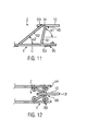
- the embodiment of the lattice girder 1 in the FIGS. 11 and 12 has no continuous upper flange, but instead of a continuous upper belt with free spaces Z in the longitudinal direction one behind the other anchoring elements 10, which are formed as moldings or Gurtabroughe, and where the upper bends 11 each of the two diagonal struts S1, S2 welded (Festlegungsstelle SU) or set in another way, for example, are latched.
- Each anchor element 10 protrudes in the longitudinal direction of the lattice girder 1 via the bend 11, so that the upper concrete anchoring zone VO formed in the area of, for example, the welding point SO of the diagonal strut S1 closest to the support has the supernatant UV opposite the lower concrete anchoring zone VU on each lower chord U.
- the lattice girder 1 in the FIGS. 11 and 12 can be installed like those of the previous embodiments of the concrete deck BD with respect to the support T of the point support.
Landscapes
- Engineering & Computer Science (AREA)
- Architecture (AREA)
- Civil Engineering (AREA)
- Structural Engineering (AREA)
- Chemical & Material Sciences (AREA)
- Composite Materials (AREA)
- Rod-Shaped Construction Members (AREA)
- Reinforcement Elements For Buildings (AREA)
- Road Paving Structures (AREA)
- Bridges Or Land Bridges (AREA)
Priority Applications (13)
| Application Number | Priority Date | Filing Date | Title |
|---|---|---|---|
| PT120058516T PT2698484E (pt) | 2012-08-13 | 2012-08-13 | Laje de betão treliçada ou plana apoiada em pontos |
| ES12005851.6T ES2528486T3 (es) | 2012-08-13 | 2012-08-13 | Losa de hormigón plana o en elementos soportada por puntos |
| EP12005851.6A EP2698484B1 (fr) | 2012-08-13 | 2012-08-13 | Construction en béton avec un support à point |
| DK12005851.6T DK2698484T3 (en) | 2012-08-13 | 2012-08-13 | Point-supported element or flat concrete |
| PL12005851T PL2698484T3 (pl) | 2012-08-13 | 2012-08-13 | Podparty punktowo strop betonowy płaski lub z elementów |
| KR1020157006333A KR101694361B1 (ko) | 2012-08-13 | 2013-06-18 | 평탄 콘크리트 천장 |
| JP2015525788A JP5943332B2 (ja) | 2012-08-13 | 2013-06-18 | 点支持されたコンクリート天井 |
| RU2015102734/03A RU2598950C1 (ru) | 2012-08-13 | 2013-06-18 | Точечно опирающееся элементное или плоское бетонное перекрытие |
| IN722DEN2015 IN2015DN00722A (fr) | 2012-08-13 | 2013-06-18 | |
| US14/420,891 US9469993B2 (en) | 2012-08-13 | 2013-06-18 | Point-supported element or flat concrete ceiling |
| CN201380047383.1A CN104619935B (zh) | 2012-08-13 | 2013-06-18 | 点支撑构件或混凝土平顶棚 |
| CA2879904A CA2879904C (fr) | 2012-08-13 | 2013-06-18 | Dalle en beton plate ou a elements soutenue par points |
| PCT/EP2013/062555 WO2014026781A1 (fr) | 2012-08-13 | 2013-06-18 | Dalle en béton plate ou à éléments soutenue par points |
Applications Claiming Priority (1)
| Application Number | Priority Date | Filing Date | Title |
|---|---|---|---|
| EP12005851.6A EP2698484B1 (fr) | 2012-08-13 | 2012-08-13 | Construction en béton avec un support à point |
Publications (2)
| Publication Number | Publication Date |
|---|---|
| EP2698484A1 true EP2698484A1 (fr) | 2014-02-19 |
| EP2698484B1 EP2698484B1 (fr) | 2014-11-19 |
Family
ID=46969920
Family Applications (1)
| Application Number | Title | Priority Date | Filing Date |
|---|---|---|---|
| EP12005851.6A Active EP2698484B1 (fr) | 2012-08-13 | 2012-08-13 | Construction en béton avec un support à point |
Country Status (13)
| Country | Link |
|---|---|
| US (1) | US9469993B2 (fr) |
| EP (1) | EP2698484B1 (fr) |
| JP (1) | JP5943332B2 (fr) |
| KR (1) | KR101694361B1 (fr) |
| CN (1) | CN104619935B (fr) |
| CA (1) | CA2879904C (fr) |
| DK (1) | DK2698484T3 (fr) |
| ES (1) | ES2528486T3 (fr) |
| IN (1) | IN2015DN00722A (fr) |
| PL (1) | PL2698484T3 (fr) |
| PT (1) | PT2698484E (fr) |
| RU (1) | RU2598950C1 (fr) |
| WO (1) | WO2014026781A1 (fr) |
Cited By (1)
| Publication number | Priority date | Publication date | Assignee | Title |
|---|---|---|---|---|
| BE1025767B1 (nl) * | 2018-03-01 | 2019-07-03 | Intersig Nv | Versterkingselement |
Families Citing this family (5)
| Publication number | Priority date | Publication date | Assignee | Title |
|---|---|---|---|---|
| HUE057759T2 (hu) | 2015-03-17 | 2022-06-28 | Leviat GmbH | Átszúródási vasalatelem és egy átszúródási vasalatelemmel ellátott lemezzel rendelkezõ építmény |
| US11220822B2 (en) * | 2016-07-15 | 2022-01-11 | Conbar Systems Llc | Reinforcing assemblies having downwardly-extending working members on structurally reinforcing bars for concrete slabs or other structures |
| WO2018107235A1 (fr) * | 2016-12-14 | 2018-06-21 | Starpartner Pty Ltd | Raidisseur, élément de coffrage permanent et dalle |
| KR102000534B1 (ko) * | 2017-11-03 | 2019-07-17 | 한국건설기술연구원 | 거푸집 겸용 고내구성 텍스타일 보강 패널을 이용한 철근콘크리트 구조물 시공방법 |
| AU2019338428A1 (en) * | 2018-09-10 | 2021-04-15 | Hcsl Pty Ltd | Building panel |
Citations (7)
| Publication number | Priority date | Publication date | Assignee | Title |
|---|---|---|---|---|
| US6006483A (en) * | 1997-02-28 | 1999-12-28 | Haedong Metal Co., Ltd. | Deck panel for reinforced concrete slabs |
| DE20103059U1 (de) * | 2001-02-21 | 2001-05-10 | Ambrosch, Adolf, 64331 Weiterstadt | Decke in Gebäuden |
| EP1070800B1 (fr) | 1999-07-19 | 2003-10-29 | Filigran Trägersysteme GmbH & Co. KG | Armature de cisaillement pour dalles planes |
| DE102007047616A1 (de) | 2006-10-05 | 2008-04-10 | Badische Drahtwerke Gmbh | Gitterträger |
| WO2009010366A1 (fr) * | 2007-07-19 | 2009-01-22 | Leone, Lucio | Poutres perfectionnées pour renforcer le béton et procédé pour les relier à des piliers afin de fournir une continuité d'une baie à une autre |
| EP2050887A2 (fr) * | 2007-10-19 | 2009-04-22 | Filigran Trägersysteme GmbH & Co. KG | Poutre en treillis |
| US20120137619A1 (en) * | 2010-12-03 | 2012-06-07 | Martter Richard P | Reinforcing assembly and reinforced structure using a reinforcing assembly |
Family Cites Families (21)
| Publication number | Priority date | Publication date | Assignee | Title |
|---|---|---|---|---|
| US1335886A (en) * | 1917-05-18 | 1920-04-06 | William H Evers | Building construction |
| US1748423A (en) * | 1923-02-16 | 1930-02-25 | Macomber Steel Company | Method of making structural units |
| US2420860A (en) * | 1945-11-13 | 1947-05-20 | Bingham F Burner | High chair and tie for reenforcing rods |
| US3305988A (en) * | 1965-01-15 | 1967-02-28 | Hally Stamping & Mfg Co | Truss anchorage |
| US3400508A (en) * | 1966-06-07 | 1968-09-10 | Avi Alpenlaendische Vered | Framework girder without lower chord |
| DE2026425A1 (de) * | 1970-05-29 | 1971-12-09 | Epitestudomanyi Intezet, Budapest | Stahlbeton-Profilbalken mit Konsolen-Ausbildung |
| AR204992A1 (es) * | 1973-06-13 | 1976-03-31 | Rheinische Filigranbau Gmbh Co | Vigas de celosia para armadura de hormigon procedimiento y aparato para su fabricacion |
| US4494349A (en) * | 1982-07-28 | 1985-01-22 | Clements Arthur C | Truss structure |
| US4689867A (en) * | 1982-09-27 | 1987-09-01 | Tolliver Wilbur E | Concrete reinforcement spacer and method of use |
| AT378218B (de) * | 1983-04-20 | 1985-07-10 | Bucher Franz | Gittertraeger |
| ES2068110B1 (es) * | 1992-12-18 | 1996-12-16 | Herman Storch | Una malla estructural, para ser utilizada en componentes resistentes de sistemas constructivos. |
| DE19613090B4 (de) * | 1995-04-05 | 2005-09-29 | Luftschiffbau Zeppelin Gmbh | Träger für ein Luftschiff |
| GB2300654A (en) * | 1995-05-04 | 1996-11-13 | Univ Sheffield | Shear reinforcement for reinforced concrete |
| CH690920A5 (de) * | 1995-12-30 | 2001-02-28 | Ancotech Ag | Bewehrung für auf Stützen aufgelagerte Flachdecken, Schubbewehrungselement sowie ein Verfahren zur Herstellung einer Bewehrung. |
| KR200251425Y1 (ko) * | 2001-07-16 | 2001-11-17 | 주식회사 슈퍼데크코리아 | 철근 콘크리트 슬래브의 데크거어더 |
| AU2005274371B2 (en) * | 2004-08-13 | 2010-11-11 | Bam Ag | Steel-concrete hollow bodied slab or ceiling |
| US20080028719A1 (en) * | 2006-02-27 | 2008-02-07 | Rutledge Richard J | Floor truss systems and methods |
| KR101021854B1 (ko) * | 2008-02-21 | 2011-03-17 | 주식회사 종합건축사사무소근정 | 하프 프리캐스트 합성 슬래브 및 이의 제조방법 |
| CN101565988A (zh) * | 2008-04-21 | 2009-10-28 | 万科企业股份有限公司 | 预制混凝土板专用桁架筋、预制板及楼板或墙的施工方法 |
| US20140059967A1 (en) * | 2010-12-03 | 2014-03-06 | Richard P. Martter | Reinforcing assembly having working members with non-planar tips |
| US8511935B1 (en) * | 2012-02-10 | 2013-08-20 | James Thomas | Pavement dowel assembly bar |
-
2012
- 2012-08-13 PL PL12005851T patent/PL2698484T3/pl unknown
- 2012-08-13 EP EP12005851.6A patent/EP2698484B1/fr active Active
- 2012-08-13 PT PT120058516T patent/PT2698484E/pt unknown
- 2012-08-13 DK DK12005851.6T patent/DK2698484T3/en active
- 2012-08-13 ES ES12005851.6T patent/ES2528486T3/es active Active
-
2013
- 2013-06-18 CA CA2879904A patent/CA2879904C/fr active Active
- 2013-06-18 US US14/420,891 patent/US9469993B2/en active Active
- 2013-06-18 CN CN201380047383.1A patent/CN104619935B/zh not_active Expired - Fee Related
- 2013-06-18 RU RU2015102734/03A patent/RU2598950C1/ru active
- 2013-06-18 KR KR1020157006333A patent/KR101694361B1/ko not_active Expired - Fee Related
- 2013-06-18 IN IN722DEN2015 patent/IN2015DN00722A/en unknown
- 2013-06-18 JP JP2015525788A patent/JP5943332B2/ja not_active Expired - Fee Related
- 2013-06-18 WO PCT/EP2013/062555 patent/WO2014026781A1/fr not_active Ceased
Patent Citations (8)
| Publication number | Priority date | Publication date | Assignee | Title |
|---|---|---|---|---|
| US6006483A (en) * | 1997-02-28 | 1999-12-28 | Haedong Metal Co., Ltd. | Deck panel for reinforced concrete slabs |
| EP1070800B1 (fr) | 1999-07-19 | 2003-10-29 | Filigran Trägersysteme GmbH & Co. KG | Armature de cisaillement pour dalles planes |
| DE20103059U1 (de) * | 2001-02-21 | 2001-05-10 | Ambrosch, Adolf, 64331 Weiterstadt | Decke in Gebäuden |
| DE102007047616A1 (de) | 2006-10-05 | 2008-04-10 | Badische Drahtwerke Gmbh | Gitterträger |
| WO2009010366A1 (fr) * | 2007-07-19 | 2009-01-22 | Leone, Lucio | Poutres perfectionnées pour renforcer le béton et procédé pour les relier à des piliers afin de fournir une continuité d'une baie à une autre |
| EP2050887A2 (fr) * | 2007-10-19 | 2009-04-22 | Filigran Trägersysteme GmbH & Co. KG | Poutre en treillis |
| EP2050887B1 (fr) | 2007-10-19 | 2012-02-22 | Filigran Trägersysteme GmbH & Co. KG | Poutre en treillis |
| US20120137619A1 (en) * | 2010-12-03 | 2012-06-07 | Martter Richard P | Reinforcing assembly and reinforced structure using a reinforcing assembly |
Non-Patent Citations (1)
| Title |
|---|
| BETON- UND STAHLBETONBAU, vol. 98, no. 6, 2003 |
Cited By (3)
| Publication number | Priority date | Publication date | Assignee | Title |
|---|---|---|---|---|
| BE1025767B1 (nl) * | 2018-03-01 | 2019-07-03 | Intersig Nv | Versterkingselement |
| EP3533946A1 (fr) * | 2018-03-01 | 2019-09-04 | Intersig NV | Élément d'armature |
| BE1026060B1 (nl) * | 2018-03-01 | 2019-10-01 | Intersig Nv | Versterkingselement |
Also Published As
| Publication number | Publication date |
|---|---|
| PT2698484E (pt) | 2015-02-04 |
| JP2015528533A (ja) | 2015-09-28 |
| US9469993B2 (en) | 2016-10-18 |
| RU2598950C1 (ru) | 2016-10-10 |
| US20150204074A1 (en) | 2015-07-23 |
| WO2014026781A1 (fr) | 2014-02-20 |
| DK2698484T3 (en) | 2015-02-02 |
| KR20150042267A (ko) | 2015-04-20 |
| CN104619935A (zh) | 2015-05-13 |
| CN104619935B (zh) | 2016-08-24 |
| CA2879904A1 (fr) | 2014-02-20 |
| JP5943332B2 (ja) | 2016-07-05 |
| ES2528486T3 (es) | 2015-02-10 |
| CA2879904C (fr) | 2017-02-14 |
| EP2698484B1 (fr) | 2014-11-19 |
| PL2698484T3 (pl) | 2015-03-31 |
| IN2015DN00722A (fr) | 2015-07-10 |
| KR101694361B1 (ko) | 2017-01-09 |
Similar Documents
| Publication | Publication Date | Title |
|---|---|---|
| DE69516267T2 (de) | Verbessertes decksystem | |
| EP2698484B1 (fr) | Construction en béton avec un support à point | |
| EP2050887B1 (fr) | Poutre en treillis | |
| EP0755473B1 (fr) | Bande a goujons pour barres relevees | |
| DE2727159C3 (de) | Schubbewehrung für auf Betonstützen aufgelagerte Flachdecken aus Stahl- oder Spannbeton | |
| EP0499590B1 (fr) | Elément connecteur isolant pour planchers de balcon et l'usage de cet élément | |
| EP2459813B1 (fr) | Élément de béton armé à armature formée d'éléments de tôle en l | |
| DE102010025042A1 (de) | Stahlträger für Fertigteildecken | |
| DE3318431C2 (de) | Deckenelement | |
| CH665668A5 (de) | Buegelkorb. | |
| EP2459812B1 (fr) | Élément de béton armé à armature formée d'éléments de tôle en z | |
| DE3820476A1 (de) | Verfahren zur montage einer mit ortbeton vergiessbaren deckenschalung | |
| EP2166171B1 (fr) | Armature de poinçonnement d'une structure en béton armé contre le poinçonnement aux alentours de la zone d'appui d'une dalle | |
| EP1630315A1 (fr) | Élément de construction pour armature de cisaillement et de poinconnement | |
| EP3617415B1 (fr) | Élément d'armature de poinçonnement et construction dotée d'une plaque dotée d'un élément d'armature de poinçonnement | |
| EP0811731A1 (fr) | Structure et élément de plafond | |
| EP0833014B1 (fr) | Système d'armature pour maçonnerie | |
| EP3228773A1 (fr) | Élément de renfort | |
| DE60007824T2 (de) | Gitterträger | |
| EP1703036B1 (fr) | Élément de construction pour armature de cisaillement et de poinçonnement | |
| DE102005030409B4 (de) | Wendelförmiges Bewehrungselement | |
| DE102020114611B3 (de) | Schalungsanordnung | |
| EP1070800A1 (fr) | Armature de cisaillement pour dalles planes | |
| AT503489B1 (de) | Bauelement | |
| AT522366B1 (de) | Bewehrungselement, Betonbauelement und Verfahren zum Herstellen eines Betonbauelements |
Legal Events
| Date | Code | Title | Description |
|---|---|---|---|
| AK | Designated contracting states |
Kind code of ref document: A1 Designated state(s): AL AT BE BG CH CY CZ DE DK EE ES FI FR GB GR HR HU IE IS IT LI LT LU LV MC MK MT NL NO PL PT RO RS SE SI SK SM TR |
|
| AX | Request for extension of the european patent |
Extension state: BA ME |
|
| PUAI | Public reference made under article 153(3) epc to a published international application that has entered the european phase |
Free format text: ORIGINAL CODE: 0009012 |
|
| 17P | Request for examination filed |
Effective date: 20140319 |
|
| RBV | Designated contracting states (corrected) |
Designated state(s): AL AT BE BG CH CY CZ DE DK EE ES FI FR GB GR HR HU IE IS IT LI LT LU LV MC MK MT NL NO PL PT RO RS SE SI SK SM TR |
|
| GRAP | Despatch of communication of intention to grant a patent |
Free format text: ORIGINAL CODE: EPIDOSNIGR1 |
|
| INTG | Intention to grant announced |
Effective date: 20140605 |
|
| GRAS | Grant fee paid |
Free format text: ORIGINAL CODE: EPIDOSNIGR3 |
|
| GRAA | (expected) grant |
Free format text: ORIGINAL CODE: 0009210 |
|
| AK | Designated contracting states |
Kind code of ref document: B1 Designated state(s): AL AT BE BG CH CY CZ DE DK EE ES FI FR GB GR HR HU IE IS IT LI LT LU LV MC MK MT NL NO PL PT RO RS SE SI SK SM TR |
|
| REG | Reference to a national code |
Ref country code: GB Ref legal event code: FG4D Free format text: NOT ENGLISH |
|
| REG | Reference to a national code |
Ref country code: CH Ref legal event code: EP |
|
| REG | Reference to a national code |
Ref country code: AT Ref legal event code: REF Ref document number: 697142 Country of ref document: AT Kind code of ref document: T Effective date: 20141215 Ref country code: CH Ref legal event code: NV Representative=s name: BOVARD AG, CH |
|
| REG | Reference to a national code |
Ref country code: IE Ref legal event code: FG4D Free format text: LANGUAGE OF EP DOCUMENT: GERMAN |
|
| REG | Reference to a national code |
Ref country code: DE Ref legal event code: R096 Ref document number: 502012001605 Country of ref document: DE Effective date: 20141231 |
|
| REG | Reference to a national code |
Ref country code: SE Ref legal event code: TRGR |
|
| REG | Reference to a national code |
Ref country code: DK Ref legal event code: T3 Effective date: 20150128 |
|
| REG | Reference to a national code |
Ref country code: RO Ref legal event code: EPE |
|
| REG | Reference to a national code |
Ref country code: PT Ref legal event code: SC4A Free format text: AVAILABILITY OF NATIONAL TRANSLATION Effective date: 20150112 |
|
| REG | Reference to a national code |
Ref country code: NO Ref legal event code: T2 Effective date: 20141119 |
|
| REG | Reference to a national code |
Ref country code: ES Ref legal event code: FG2A Ref document number: 2528486 Country of ref document: ES Kind code of ref document: T3 Effective date: 20150210 |
|
| REG | Reference to a national code |
Ref country code: NL Ref legal event code: T3 |
|
| REG | Reference to a national code |
Ref country code: GR Ref legal event code: EP Ref document number: 20140402590 Country of ref document: GR Effective date: 20150128 |
|
| REG | Reference to a national code |
Ref country code: PL Ref legal event code: T3 |
|
| REG | Reference to a national code |
Ref country code: LT Ref legal event code: MG4D |
|
| PG25 | Lapsed in a contracting state [announced via postgrant information from national office to epo] |
Ref country code: FI Free format text: LAPSE BECAUSE OF FAILURE TO SUBMIT A TRANSLATION OF THE DESCRIPTION OR TO PAY THE FEE WITHIN THE PRESCRIBED TIME-LIMIT Effective date: 20141119 Ref country code: IS Free format text: LAPSE BECAUSE OF FAILURE TO SUBMIT A TRANSLATION OF THE DESCRIPTION OR TO PAY THE FEE WITHIN THE PRESCRIBED TIME-LIMIT Effective date: 20150319 Ref country code: LT Free format text: LAPSE BECAUSE OF FAILURE TO SUBMIT A TRANSLATION OF THE DESCRIPTION OR TO PAY THE FEE WITHIN THE PRESCRIBED TIME-LIMIT Effective date: 20141119 |
|
| REG | Reference to a national code |
Ref country code: SK Ref legal event code: T3 Ref document number: E 18018 Country of ref document: SK |
|
| PG25 | Lapsed in a contracting state [announced via postgrant information from national office to epo] |
Ref country code: HR Free format text: LAPSE BECAUSE OF FAILURE TO SUBMIT A TRANSLATION OF THE DESCRIPTION OR TO PAY THE FEE WITHIN THE PRESCRIBED TIME-LIMIT Effective date: 20141119 Ref country code: RS Free format text: LAPSE BECAUSE OF FAILURE TO SUBMIT A TRANSLATION OF THE DESCRIPTION OR TO PAY THE FEE WITHIN THE PRESCRIBED TIME-LIMIT Effective date: 20141119 Ref country code: LV Free format text: LAPSE BECAUSE OF FAILURE TO SUBMIT A TRANSLATION OF THE DESCRIPTION OR TO PAY THE FEE WITHIN THE PRESCRIBED TIME-LIMIT Effective date: 20141119 Ref country code: CY Free format text: LAPSE BECAUSE OF FAILURE TO SUBMIT A TRANSLATION OF THE DESCRIPTION OR TO PAY THE FEE WITHIN THE PRESCRIBED TIME-LIMIT Effective date: 20141119 |
|
| REG | Reference to a national code |
Ref country code: HU Ref legal event code: AG4A Ref document number: E022691 Country of ref document: HU |
|
| PG25 | Lapsed in a contracting state [announced via postgrant information from national office to epo] |
Ref country code: EE Free format text: LAPSE BECAUSE OF FAILURE TO SUBMIT A TRANSLATION OF THE DESCRIPTION OR TO PAY THE FEE WITHIN THE PRESCRIBED TIME-LIMIT Effective date: 20141119 |
|
| REG | Reference to a national code |
Ref country code: DE Ref legal event code: R097 Ref document number: 502012001605 Country of ref document: DE |
|
| PLBE | No opposition filed within time limit |
Free format text: ORIGINAL CODE: 0009261 |
|
| STAA | Information on the status of an ep patent application or granted ep patent |
Free format text: STATUS: NO OPPOSITION FILED WITHIN TIME LIMIT |
|
| 26N | No opposition filed |
Effective date: 20150820 |
|
| PG25 | Lapsed in a contracting state [announced via postgrant information from national office to epo] |
Ref country code: SI Free format text: LAPSE BECAUSE OF FAILURE TO SUBMIT A TRANSLATION OF THE DESCRIPTION OR TO PAY THE FEE WITHIN THE PRESCRIBED TIME-LIMIT Effective date: 20141119 |
|
| PG25 | Lapsed in a contracting state [announced via postgrant information from national office to epo] |
Ref country code: LU Free format text: LAPSE BECAUSE OF FAILURE TO SUBMIT A TRANSLATION OF THE DESCRIPTION OR TO PAY THE FEE WITHIN THE PRESCRIBED TIME-LIMIT Effective date: 20150813 Ref country code: MC Free format text: LAPSE BECAUSE OF FAILURE TO SUBMIT A TRANSLATION OF THE DESCRIPTION OR TO PAY THE FEE WITHIN THE PRESCRIBED TIME-LIMIT Effective date: 20141119 |
|
| REG | Reference to a national code |
Ref country code: FR Ref legal event code: PLFP Year of fee payment: 5 |
|
| PG25 | Lapsed in a contracting state [announced via postgrant information from national office to epo] |
Ref country code: MT Free format text: LAPSE BECAUSE OF FAILURE TO SUBMIT A TRANSLATION OF THE DESCRIPTION OR TO PAY THE FEE WITHIN THE PRESCRIBED TIME-LIMIT Effective date: 20141119 |
|
| PG25 | Lapsed in a contracting state [announced via postgrant information from national office to epo] |
Ref country code: SM Free format text: LAPSE BECAUSE OF FAILURE TO SUBMIT A TRANSLATION OF THE DESCRIPTION OR TO PAY THE FEE WITHIN THE PRESCRIBED TIME-LIMIT Effective date: 20141119 |
|
| REG | Reference to a national code |
Ref country code: FR Ref legal event code: PLFP Year of fee payment: 6 |
|
| PG25 | Lapsed in a contracting state [announced via postgrant information from national office to epo] |
Ref country code: MK Free format text: LAPSE BECAUSE OF FAILURE TO SUBMIT A TRANSLATION OF THE DESCRIPTION OR TO PAY THE FEE WITHIN THE PRESCRIBED TIME-LIMIT Effective date: 20141119 |
|
| REG | Reference to a national code |
Ref country code: FR Ref legal event code: PLFP Year of fee payment: 7 |
|
| PG25 | Lapsed in a contracting state [announced via postgrant information from national office to epo] |
Ref country code: AL Free format text: LAPSE BECAUSE OF FAILURE TO SUBMIT A TRANSLATION OF THE DESCRIPTION OR TO PAY THE FEE WITHIN THE PRESCRIBED TIME-LIMIT Effective date: 20141119 |
|
| PGFP | Annual fee paid to national office [announced via postgrant information from national office to epo] |
Ref country code: TR Payment date: 20220809 Year of fee payment: 11 Ref country code: SK Payment date: 20220720 Year of fee payment: 11 Ref country code: PT Payment date: 20220719 Year of fee payment: 11 Ref country code: ES Payment date: 20220901 Year of fee payment: 11 Ref country code: DK Payment date: 20220818 Year of fee payment: 11 Ref country code: BG Payment date: 20220831 Year of fee payment: 11 |
|
| PGFP | Annual fee paid to national office [announced via postgrant information from national office to epo] |
Ref country code: GR Payment date: 20220829 Year of fee payment: 11 |
|
| PGFP | Annual fee paid to national office [announced via postgrant information from national office to epo] |
Ref country code: CH Payment date: 20220829 Year of fee payment: 11 |
|
| REG | Reference to a national code |
Ref country code: DK Ref legal event code: EBP Effective date: 20230831 |
|
| REG | Reference to a national code |
Ref country code: SK Ref legal event code: MM4A Ref document number: E 18018 Country of ref document: SK Effective date: 20230813 |
|
| REG | Reference to a national code |
Ref country code: CH Ref legal event code: PL |
|
| PG25 | Lapsed in a contracting state [announced via postgrant information from national office to epo] |
Ref country code: GR Free format text: LAPSE BECAUSE OF NON-PAYMENT OF DUE FEES Effective date: 20240307 |
|
| PG25 | Lapsed in a contracting state [announced via postgrant information from national office to epo] |
Ref country code: GR Free format text: LAPSE BECAUSE OF NON-PAYMENT OF DUE FEES Effective date: 20240307 Ref country code: BG Free format text: LAPSE BECAUSE OF NON-PAYMENT OF DUE FEES Effective date: 20240229 Ref country code: PT Free format text: LAPSE BECAUSE OF NON-PAYMENT OF DUE FEES Effective date: 20240213 Ref country code: SK Free format text: LAPSE BECAUSE OF NON-PAYMENT OF DUE FEES Effective date: 20230813 Ref country code: CH Free format text: LAPSE BECAUSE OF NON-PAYMENT OF DUE FEES Effective date: 20230831 |
|
| PG25 | Lapsed in a contracting state [announced via postgrant information from national office to epo] |
Ref country code: DK Free format text: LAPSE BECAUSE OF NON-PAYMENT OF DUE FEES Effective date: 20230831 |
|
| PG25 | Lapsed in a contracting state [announced via postgrant information from national office to epo] |
Ref country code: DK Free format text: LAPSE BECAUSE OF NON-PAYMENT OF DUE FEES Effective date: 20230831 |
|
| REG | Reference to a national code |
Ref country code: ES Ref legal event code: FD2A Effective date: 20240927 |
|
| PG25 | Lapsed in a contracting state [announced via postgrant information from national office to epo] |
Ref country code: ES Free format text: LAPSE BECAUSE OF NON-PAYMENT OF DUE FEES Effective date: 20230814 |
|
| PG25 | Lapsed in a contracting state [announced via postgrant information from national office to epo] |
Ref country code: ES Free format text: LAPSE BECAUSE OF NON-PAYMENT OF DUE FEES Effective date: 20230814 |
|
| PGFP | Annual fee paid to national office [announced via postgrant information from national office to epo] |
Ref country code: NL Payment date: 20250826 Year of fee payment: 14 |
|
| PGFP | Annual fee paid to national office [announced via postgrant information from national office to epo] |
Ref country code: HU Payment date: 20250822 Year of fee payment: 14 |
|
| PGFP | Annual fee paid to national office [announced via postgrant information from national office to epo] |
Ref country code: DE Payment date: 20250828 Year of fee payment: 14 |
|
| PGFP | Annual fee paid to national office [announced via postgrant information from national office to epo] |
Ref country code: NO Payment date: 20250829 Year of fee payment: 14 |
|
| PGFP | Annual fee paid to national office [announced via postgrant information from national office to epo] |
Ref country code: IT Payment date: 20250827 Year of fee payment: 14 Ref country code: PL Payment date: 20250813 Year of fee payment: 14 |
|
| PGFP | Annual fee paid to national office [announced via postgrant information from national office to epo] |
Ref country code: BE Payment date: 20250822 Year of fee payment: 14 Ref country code: GB Payment date: 20250827 Year of fee payment: 14 |
|
| PGFP | Annual fee paid to national office [announced via postgrant information from national office to epo] |
Ref country code: FR Payment date: 20250826 Year of fee payment: 14 Ref country code: AT Payment date: 20250822 Year of fee payment: 14 |
|
| PGFP | Annual fee paid to national office [announced via postgrant information from national office to epo] |
Ref country code: SE Payment date: 20250827 Year of fee payment: 14 |
|
| PGFP | Annual fee paid to national office [announced via postgrant information from national office to epo] |
Ref country code: CZ Payment date: 20250813 Year of fee payment: 14 Ref country code: IE Payment date: 20250824 Year of fee payment: 14 |
|
| PGFP | Annual fee paid to national office [announced via postgrant information from national office to epo] |
Ref country code: RO Payment date: 20250813 Year of fee payment: 14 |