EP2698488A2 - Système de liasion de support - Google Patents
Système de liasion de support Download PDFInfo
- Publication number
- EP2698488A2 EP2698488A2 EP13183534.0A EP13183534A EP2698488A2 EP 2698488 A2 EP2698488 A2 EP 2698488A2 EP 13183534 A EP13183534 A EP 13183534A EP 2698488 A2 EP2698488 A2 EP 2698488A2
- Authority
- EP
- European Patent Office
- Prior art keywords
- anchor
- composite
- carrier
- mast
- core
- Prior art date
- Legal status (The legal status is an assumption and is not a legal conclusion. Google has not performed a legal analysis and makes no representation as to the accuracy of the status listed.)
- Withdrawn
Links
Images






Classifications
-
- E—FIXED CONSTRUCTIONS
- E04—BUILDING
- E04H—BUILDINGS OR LIKE STRUCTURES FOR PARTICULAR PURPOSES; SWIMMING OR SPLASH BATHS OR POOLS; MASTS; FENCING; TENTS OR CANOPIES, IN GENERAL
- E04H12/00—Towers; Masts or poles; Chimney stacks; Water-towers; Methods of erecting such structures
- E04H12/02—Structures made of specified materials
- E04H12/04—Structures made of specified materials of wood
-
- E—FIXED CONSTRUCTIONS
- E04—BUILDING
- E04B—GENERAL BUILDING CONSTRUCTIONS; WALLS, e.g. PARTITIONS; ROOFS; FLOORS; CEILINGS; INSULATION OR OTHER PROTECTION OF BUILDINGS
- E04B1/00—Constructions in general; Structures which are not restricted either to walls, e.g. partitions, or floors or ceilings or roofs
- E04B1/18—Structures comprising elongated load-supporting parts, e.g. columns, girders, skeletons
- E04B1/26—Structures comprising elongated load-supporting parts, e.g. columns, girders, skeletons the supporting parts consisting of wood
- E04B1/2604—Connections specially adapted therefor
-
- E—FIXED CONSTRUCTIONS
- E04—BUILDING
- E04H—BUILDINGS OR LIKE STRUCTURES FOR PARTICULAR PURPOSES; SWIMMING OR SPLASH BATHS OR POOLS; MASTS; FENCING; TENTS OR CANOPIES, IN GENERAL
- E04H12/00—Towers; Masts or poles; Chimney stacks; Water-towers; Methods of erecting such structures
- E04H12/24—Cross arms
Definitions
- the invention relates to a carrier composite system with at least two interconnected carriers. It relates in particular to a mast arrangement.
- Medium- and low-voltage networks use wooden pole arrangements that carry trusses to which power lines are attached.
- the trusses are usually steel tubes or double T-beams made of steel, which are connected to the wooden mast assembly via angled U-profiles, the U-profiles are attached with clips at the top of the wooden pole assembly.
- the wooden pole arrangement can consist of a simple, anchored in the ground, upright wooden pole.
- wood double masts are used.
- the double masts may for example be arranged in the shape of the outer legs of an A's be, wherein they are held together at its upper end by threaded therethrough threaded rods and are arranged underneath at different heights cross struts for stabilizing the masts.
- the masts formed from each round timber run parallel, with double T-pieces are provided as spacers between the masts and the masts respectively at the level of the double T-pieces over long bolts that passed horizontally through the mast are pressed to the double tees.
- the invention has for its object to provide a carrier composite system that is statically predictable and can be designed with the mast arrangements load-oriented and cost-effective.
- a composite anchor is understood here and below to mean a component having a core which carries a large number of anchor pins.
- the core may have a symmetrical or asymmetrical shape.
- Elongated cores with a square or diamond-shaped cross section have proven to be practically relevant core shapes. But it can also be used as polyhedron cores or other symmetrical or asymmetrical cores used.
- the anchor pins may extend in opposite directions only parallel to one another or on opposite sides of the core.
- a composite anchor as a node connection for two or more carriers with at least two acting in different directions anchor pin areas, especially if the core is a polyhedron.
- the anchors can be designed according to need with one or more through holes longitudinally or transversely through its core and serve as a so-called push-through anchors as a bearing for threaded pins. You can also have threaded holes for screws to be attached to the anchor.
- the anchor pins may have a round or polygonal cross-section, and be formed in particular as thorns.
- the composite anchors may be integrally or multiply formed from one or different materials.
- both tensile and compressive forces as well as the shear and shear forces occurring between the carriers to be connected are transferred particularly well as connecting elements, because the anchor pins do not transmit the forces on the outside of a carrier on this, but initiate into its interior.
- a mast arrangement based on such a carrier composite system can be statically calculated for the first time, so that the selection of the materials used and the material thicknesses can be determined for the first time on the basis of calculations of the expected load cases.
- the materials for the beams and the composite anchor can be chosen so that the composite anchor can be pressed into the outer surface of the carrier. This is possible in particular when the mast in the region of the anchor receptacle has a rubber-like material which has elastic properties within certain limits.
- the anchor pins have one or more undercuts, so that the formed by the undercuts circumferential edges of the anchor pin press into the surface of the resulting from the press-fitting, the composite anchor can sit firmly in the recording.
- recesses are preferably provided on the outer surface of the carrier, especially in wooden supports before the anchor pins of the composite anchor are inserted into the receptacles in the outer surface of the carrier.
- means are provided for securing the composite anchor engaging in the receptacles in the outer surface (s) of the carrier (s).
- means come in particular mechanical Fastening means, in particular screws or bolts into consideration, for example, engage directly in the carrier, be it parallel to the anchor pins or obliquely thereto, wherein the fastening means are preferably directly in communication with the composite anchor.
- suitable adhesives for example, two-component adhesives into consideration.
- attachment options include, for example, to secure the composite anchor with a cross around the composite anchor and the carrier clamp on the carrier.
- the composite anchor can lie directly between two or more carriers, these carriers can be held together with other fasteners such as screws, clamps or the like, so that the composite anchor is securely held in position between the carriers.
- the composite anchor is provided with anchor pins for each of these carriers and engages with these in the carrier in order to achieve the best possible transfer of forces from carrier to carrier.
- the composite anchor has only anchor pins for one of the carriers to be connected and is connected to another carrier via other means.
- a composite anchor which engages on one side with anchor pins in a mast and is fastened for example by a screw on the mast, be connected on the other side with a cross-member carrying U-profile, for example via rivets, a weld or a screw.
- the carriers connected to one another via a composite anchor at least partially abut each other, it is advantageous if they are flat in the abutting areas.
- creating a planar abutment surface is much easier than creating a profiled surface.
- the structure of the invention is, as already stated above, particularly suitable for mast arrangements, in particular for use as poles in medium-voltage, low-voltage and high-voltage networks up to 360 kV, or for use in telecommunication networks, e.g. Telephone transmission towers.
- they can be provided with a traverse which is connected to the mast arrangement via one or more composite anchors.
- Suitable mast arrangements consist, for example, of at least two A-shaped, interconnected, interconnected anchors, upright carriers.
- a mast arrangement can be formed in three sockets with three upright carriers, which are connected to one another via one or more composite anchors.
- the mast arrangements according to the invention can be provided with stiffeners for their stiffening.
- Such cross member may have an internal composite anchor, as he, for example, from DE 297 23 866 U1 is known, engage in cooperating with at least one of the upright support mechanical connecting means, such as bolts.
- the carrier composite system according to the invention is particularly suitable for carriers made of wood or a wood composite material and is particularly suitable for structures made of round timbers.
- the carriers may also consist, for example, of a plastic material, a concrete material or other suitable materials.
- the webs of the composite anchors according to the invention can serve, in particular, to secure a composite anchor inserted into a (wooden) support and engaging it with its anchor pins against the slipping on the support with screws.
- the shape and orientation of the webs can be adapted to the outer surface of a carrier to which they are to be applied. For example, depending on the requirements, they can be curved or project obliquely from the core.
- the composite anchor may have a continuous contact surface formed by an outer surface of the core and an outer surface of at least one of the webs for a carrier, which is curved, for example, flat or transverse to the longitudinal axis of the composite anchor as required.
- the composite anchor has a through hole extending in the direction of the longitudinal axis of the core, in particular a through hole.
- the anchor can serve as a receptacle for a guide or locking pin over which other carrier or functional parts are connected to the anchor can, such as horizontal support profiles for receiving transformers or the like.
- the armature core has at least two mutually spaced, mutually aligned armature core parts.
- the material required for the production of the anchor and thus also its own weight can be reduced.
- such an embodiment also offers the advantage that a composite anchor designed in this way can be connected to one or more support and / or functional elements via more than one guide or locking pin.
- the composite anchors are preferably produced as castings due to the simple shape. Suitable materials are metal alloys into consideration; but it can also be used, for example, readily plastics.
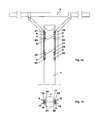
- the in the FIGS. 1a and 1b illustrated support structure consists of a single mast 1 formed from a round timber, a traverse. 2 and two U-profiles 3, 4, which are arranged on opposite sides of the single mast 1, a lower, parallel to the side surface of the single mast 1 extending region and an upper, obliquely outwardly extending region and at the upper ends of the traverse 2 is mounted ,
- the U-profiles 3, 4 are connected to the single mast 1 via in each case an upper composite anchor 5, 6 and a lower composite anchor 7, 8.
- the composite anchors have an elongated core.
- anchor pins are provided which extend perpendicular to the bottom surface of the U-profiles and towards the single mast 1 out.
- the anchor pins engage in recordings 9, 11 provided in the single mast 1.
- the composite anchors 5, 6, 7, 8 are connected to the respective U-profile 3, 4 on at least one side of its core and can simply be screwed or welded, for example, with this on its side facing away from the single mast.
- the core of the composite anchor on at least one bore along its longitudinal axis as a receptacle for a guide pin attached to the U-profile. Examples of such anchors are described with reference to FIGS FIGS. 7a, 7b . 7d . 8th . 9a . 9b . 9c and 9d described.
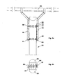
- FIGS. 2a and 2b is another embodiment of a carrier composite system according to the invention, this time with a double mast 31 from two mutually parallel roundwoods 32, 33 shown.
- the logs are held together by means not shown, passing horizontally through them bolts.
- an upper composite anchor 34 and a lower composite anchor 35 are arranged between the round timbers 32, 33.
- Both composite anchors 34, 35 each have a horizontally extending, elongate core 36 whose longitudinal axis is tangent to both roundwoods.
- the composite anchors 34, 35 also have a plurality of mutually parallel anchor pins, which engage on both sides of the core from the outside into corresponding recesses in the round timber.
- Both composite anchors 34, 35 each have at both ends threaded holes in the screws 37, 38, 39, 41 are screwed for fixing U-profiles 42, 43, wherein the U-profiles 42, 43 as in the in FIGS. 1a and 1b embodiment shown above the mast extending Traverse 44 hold.
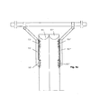
- FIGS. 3a to 3d illustrated carrier composite system differs from that in the FIGS. 1a and 1b merely shown in that instead of the single mast 1, a double mast of two mutually parallel round logs 51, 52 is provided, which are not shown here, by both round logs 51, 51 'horizontally passing bolts are firmly connected to each other, with the U Profiles 52, 52 'connected upper and lower composite anchors 53, 53' engage in the opposite outer sides of the double mast.
- the composite anchors 53, 53 ' are vertical extending through holes provided in the guide pin 54 'engage, which are firmly connected via tabs 55' with the U-profiles 52 'and secured by pins 56' at their free ends against being pulled out.
- both embodiments with double masts can for stabilizing the masts against each other intervening, preferably - as in the FIGS. 3b and 3c shown - vertical, but also horizontally or obliquely arranged composite anchors 57 may be provided which engage with anchoring pins provided on both sides in the masts.
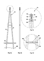
- FIGS. 4a to 4c is a simple mast construction with a vertical single mast 61 shown, which is embedded in the bottom 62 and stabilized at its lower end via a cross member 63.
- the single mast 61 is supported by a likewise inserted into the bottom 62, obliquely attached to the upper end of the single mast 61 strut 64.
- Strut 64 and single mast 61 are connected in the area in which they abut each other via an elongate composite anchor 65 which is vertically arranged and engages with its anchor pins in both the single mast 61, and in the strut 64.
- Strut 64 and single mast 61 are also connected to each other via an upper bolt 66 and a lower bolt 67, so that the composite anchor 65 is secured against slipping out of position.
- FIGS. 5a to 5d another mast construction with an A-mast 71 is shown.
- the two substantially upright running up to each other carrier 72, 73 are in the head region 74 (s. Fig. 7c ) formed flat on their sides facing each other.
- In these Flat areas are recesses for each core and the anchor pins of a first, upper, horizontally extending between the two surfaces of composite anchor 75, a second, arranged underneath, vertically extending composite anchor 76 and a third, under the second composite anchor 76 horizontally extending composite anchor 77 is provided.
- the supports 72, 73 are also connected to each other via horizontally passing therethrough, above and below the and between the composite anchor (s) 75, 76, 77 arranged bolts 78, 79, 81, 82.
- a traverse can be attached to this mast, for example via profiles on the upper and lower composite anchors 75, 77.
- the composite anchors can be provided with through holes passing through their core through holes or frontally with threaded holes, so that the profiles are either to be attached via threaded rods or screws to the composite anchors.
- the carrier 83 has a through hole extending along its longitudinal axis into which a further composite anchor 84 is embedded.
- the composite anchor 84 has threaded bores that cooperate with bolts 85, 86 passing through the beams 72 and 73 and the through hole of the beam 84 and with which the beams 72, 73 are fixedly connected to the cross member 83.
- Both carriers 72, 73 are embedded in the bottom 87 and stabilized in the ground via two horizontal cross bars 88 connecting the carriers 72, 73 and bordering on both sides.
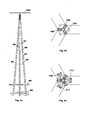
- FIGS. 6a to 6c illustrated mast construction differs from that in the FIGS. 5a to 5d represented essentially in that instead of two substantially upright carriers three carriers 91, 92, 93 are provided, which are arranged in the manner of a three-legged tripod to each other. All carriers are embedded in the bottom 94 and in the ground over parallel, horizontal cross bars 95 in pairs edged and stabilized. Also, the carriers 91, 92, 93 via cross members 97, 98, 99 connected to each other at about half the height of the mast.
- the carriers 91, 92, 93 each have two planar surfaces enclosing an angle of 120 ° as contact surfaces for the respective other two carriers.
- Recesses for the cores and anchor pins of composite anchors 101, 102, 103 are in turn provided in these surfaces which, depending on the embodiment, can optionally be arranged horizontally and / or vertically between the abutting sides of the carriers 91, 92, 93.
- the composite anchors 101, 102, 103 may have threaded holes on their outwardly directed end faces, over which, for example, the in FIG. 6a Traverse 104 shown can be attached to the head of the mast construction.
- a plurality of composite anchors can be arranged one above the other either in horizontal or vertical, possibly also oblique orientation between the abutting surfaces.
- the illustrated three-legged mast construction made of wood is particularly suitable for use for power poles for branches, which are usually carried out so far made of steel.
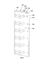
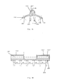
- FIGS. 7a to 7d various types of armature are shown, which can be used for the carrier composite systems according to the invention.
- Fig. 7a shows a composite anchor with a core 111 which has a substantially square cross-section. Through the core 111, a through hole 112 extends. On two adjacent longitudinal sides 113, 114 of the core 111 mutually parallel anchor pins 115 are arranged, the longitudinal axes each form an angle of 45 ° to the respective outer surface on which they are arranged.
- the anchor pins 115 are conical with a tapering away from the core Cross section formed.
- Fig. 7b illustrated composite anchor differs from that in Figure 7a shown only in that are provided at one or both ends of the composite anchor counterbores 121 at the entrance of the through hole for receiving the countersunk heads of countersunk screws.
- the through hole 112 for example, have threads on the front side or can be provided instead of the through hole at one or both ends threaded holes.
- the core can be designed as a solid core without drilling.
- the webs may, instead of lying in a plane perpendicular to the longitudinal axes of the anchor pins, be arranged so that they rest in the installed state, for example on a non-aligned surface of a carrier to which the composite anchor is to be attached.
- the webs can also be curved.
- the armature pins facing away from the outside of the core, which lies between the webs, with the adjoining sides of the webs form a continuous surface and in particular be flat.
- threaded bores for fastening carriers may be provided on the outside of the core facing away from the anchor pins.
- the composite anchors described are particularly suitable for connecting a wooden support, in particular a wooden mast, with a support made of another material, such as steel or concrete.
- Fig. 7c illustrated composite anchor differs from that in Fig. 7a illustrated in that it has a solid core 131 and armature pins 132, 133 are provided on all longitudinal sides of the core 131, wherein the longitudinal axes of the anchor pins with the outside, on which the anchor pins are respectively arranged, again enclose an angle of 45 ° and all in run parallel to each other levels.
- Fig. 7d illustrated composite anchor differs from that in FIG. 7c shown only through a centrally in the longitudinal direction through the core 134 extending through bore 135th
- anchor types with a three-, four- or polygonal core cross section used, at which extending perpendicular to the longitudinal sides anchor pins for simultaneous connection of three or more components are provided.
- Anchor types with anchor pins pointing in several directions are particularly suitable for connecting several wooden beams.
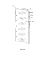
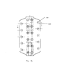
- the illustrated composite anchors differ from those in Figure 7a represented essentially in that its core 141, 151, 151 'and the webs 142, 143, 152, 153 running on both sides of the cores 141, 151, 151' on the side of the anchor pins 144, 154 have a continuous contact surface 145, 155 wherein the cross section of the core 141 in FIG Fig. 8 two to the contact surface 145 perpendicular and mutually parallel side surfaces 147, 148 and the plant surface opposite outer surface 149 having Vietnameseabismeförmigem cross section and the cross section of the core 151, 151 'in the Fig. 9a to 9d is substantially semicircular.
- the webs 142, 143, 152, 153 extend over the entire length of the core 141, 151, 151 'and are provided with a plurality of - in the illustrated examples six - through holes 146, 156.
- the contact surface 145 is flat.
- the through holes 146 are respectively disposed at the height of the anchor pins 144.
- the contact surface 155 of the in the FIGS. 9a to 9d illustrated composite anchor is concave in anchor longitudinal direction, as in particular in the FIGS. 9a and 9c you can see.
- the through holes 156 are disposed at half height of the anchor pins 154, respectively. You can - as in particular in the FIGS. 9b and 9c can be seen - at their the contact surfaces 145, 155 facing away from counterbores 158 for receiving countersunk heads of countersunk screws.
- the semi-circular body of the armature core need not extend over the entire length of the composite anchor. Rather, it may be formed of two or more mutually spaced but mutually aligned anchor portions 151, 151 ', for example, to keep the mass of the composite anchor low (s. FIG. 9d ). If the body of the armature core 151, 151 'is interrupted, it can be used as a receptacle for two guide pins arranged one above the other.
- All illustrated composite anchors are particularly suitable for use on wooden poles. So they can be easily screwed to wooden poles with self-drilling wood screws. This results in particular the advantage that the wood screws record not only acting on the connection of composite anchor and wooden mast tensile forces, but also in addition to the anchor pins thrust and shear forces loads.
- the wood screws do not run parallel but obliquely the anchor pins, in particular when the associated webs of the composite anchor are arranged correspondingly obliquely or its continuous contact surface is curved, take the wood screws tensile forces in different directions, whereby the shear anchor particularly well secured in position and part of the shear and shear forces of the screws is absorbed as tensile forces.
- FIGS. 10a to 10c is a consisting of a guide pin 161 and a tab 162 connecting element shown, which are welded via the tab 162, for example, to a U-beam and can be inserted with its guide pin 161 in the through hole of an armature core.
- the tab 162 is comparatively flat and has in plan view substantially the cross section of an isosceles, right-angled triangle. The right angle opposite end face of the tab 162 serves as a welding edge for welding to a support, such as the aforementioned U-beam.
- At the bottom of the tab 162 of the guide pin 161 is arranged, which has at its free lower end a transverse to its longitudinal axis extending through opening 163 for receiving a Sich ceremoniesssplintes.
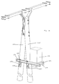
- FIG. 11 shows a further application of the carrier composite system.
- the two masts 171, 171 ' are each at the same height on opposite outer sides of the A-mast piercing anchors 172, 172', in their training in the FIGS. 9a to 9d shown through anchor 172, 172 'correspond, arranged and aligned parallel to the longitudinal axis of the masts 171, 171'.
- the carriers 173, 174 are fixedly connected to the A-mast via bolts 175, 175 'passing through them, which engage in the through bores of the composite anchors 172, 172'. In addition, they are connected at both ends by bolts 176, 177. On one side of the A-mast both beams 173, 174 cantilevered out and form a footprint for a load 178, for example for a transformer.
- FIGS. 9a to 9d illustrated through-anchor above the other and laterally offset from each other.
- a carrier element 184 can be fixedly connected to the mast 181 via guide pins 185, 186 which are fastened to one another via lugs 187, 188 correspondingly one above the other and laterally offset from one another and engage in the push-through anchors 182, 183.
- FIGS. 8 and 9a to 9d illustrated composite anchor and the in FIG. 12 Compound system shown are particularly suitable for attaching a variety of elements or functional parts of poles, such as lighting devices.
Landscapes
- Engineering & Computer Science (AREA)
- Architecture (AREA)
- Civil Engineering (AREA)
- Structural Engineering (AREA)
- Wood Science & Technology (AREA)
- Life Sciences & Earth Sciences (AREA)
- Chemical & Material Sciences (AREA)
- Materials Engineering (AREA)
- Physics & Mathematics (AREA)
- Electromagnetism (AREA)
- Joining Of Building Structures In Genera (AREA)
- Fittings On The Vehicle Exterior For Carrying Loads, And Devices For Holding Or Mounting Articles (AREA)
- Surgical Instruments (AREA)
Applications Claiming Priority (3)
| Application Number | Priority Date | Filing Date | Title |
|---|---|---|---|
| DE200610018089 DE102006018089A1 (de) | 2006-04-18 | 2006-04-18 | Verbundanker basiertes Tragwerk |
| DE202006016481U DE202006016481U1 (de) | 2006-04-18 | 2006-10-24 | Trägerverbundsystem |
| EP07724262A EP2010737A1 (fr) | 2006-04-18 | 2007-04-16 | Système de LIAISON de support |
Related Parent Applications (1)
| Application Number | Title | Priority Date | Filing Date |
|---|---|---|---|
| EP07724262A Division EP2010737A1 (fr) | 2006-04-18 | 2007-04-16 | Système de LIAISON de support |
Publications (2)
| Publication Number | Publication Date |
|---|---|
| EP2698488A2 true EP2698488A2 (fr) | 2014-02-19 |
| EP2698488A3 EP2698488A3 (fr) | 2014-04-16 |
Family
ID=38218900
Family Applications (2)
| Application Number | Title | Priority Date | Filing Date |
|---|---|---|---|
| EP07724262A Withdrawn EP2010737A1 (fr) | 2006-04-18 | 2007-04-16 | Système de LIAISON de support |
| EP13183534.0A Withdrawn EP2698488A3 (fr) | 2006-04-18 | 2007-04-16 | Système de liasion de support |
Family Applications Before (1)
| Application Number | Title | Priority Date | Filing Date |
|---|---|---|---|
| EP07724262A Withdrawn EP2010737A1 (fr) | 2006-04-18 | 2007-04-16 | Système de LIAISON de support |
Country Status (3)
| Country | Link |
|---|---|
| EP (2) | EP2010737A1 (fr) |
| DE (1) | DE202006016481U1 (fr) |
| WO (1) | WO2007121881A1 (fr) |
Cited By (2)
| Publication number | Priority date | Publication date | Assignee | Title |
|---|---|---|---|---|
| DE102017002557A1 (de) | 2017-03-17 | 2018-09-20 | Carl Scholl Gmbh | Montageset und damit bereitstellbare Mastanordnung |
| IT202200006095A1 (it) * | 2022-03-29 | 2023-09-29 | Rotho Blaas Srl Ovvero Rotho Blaas Gmbh | Dispositivo di collegamento per collegare elementi di costruzione con almeno un elemento di costruzione in legno |
Families Citing this family (10)
| Publication number | Priority date | Publication date | Assignee | Title |
|---|---|---|---|---|
| DE102007033829A1 (de) * | 2007-07-18 | 2009-01-22 | Induo Gesellschaft Zur Verwertung Von Schutzrechten Mbh & Co. Kg | Mastanordnung |
| DE102008009056A1 (de) | 2008-02-13 | 2009-08-20 | Induo Gesellschaft Zur Verwertung Von Schutzrechten Mbh & Co. Kg | Verbundanker |
| DE102010018646A1 (de) | 2010-04-28 | 2011-11-03 | Induo Gesellschaft Zur Verwertung Von Schutzrechten Mbh & Co Kg | Mastverankerung |
| DE102012101002A1 (de) | 2011-06-08 | 2012-12-13 | Induo Gesellschaft Zur Verwertung Von Schutzrechten Mbh & Co. Kg | Traversenanordnung, insbesondere für Freileitungsmaste |
| DE202012100412U1 (de) * | 2011-09-01 | 2012-12-05 | Induo Gesellschaft Zur Verwertung Von Schutzrechten Mbh & Co. Kg | Mastanordnung |
| DE102012017164A1 (de) | 2012-08-30 | 2014-03-06 | Db Netz Ag | Mastkonstruktion für gleisgebundene Oberleitungsanlagen des Schienenverkehrs |
| DE202012008305U1 (de) | 2012-08-30 | 2012-09-26 | Db Netz Ag | Mastkonstruktion für gleisgebundene Oberleitungsanlagen des Schienenverkehrs |
| CN103452370B (zh) * | 2012-10-25 | 2015-12-16 | 江苏神马电力股份有限公司 | 电网输电线用复合杆塔及其复合横担结构 |
| DE202013105485U1 (de) | 2013-12-02 | 2015-03-03 | Induo Gesellschaft Zur Verwertung Von Schutzrechten Mbh & Co. Kg | Anschluss für Mastzopf |
| DE102019113971A1 (de) * | 2019-05-24 | 2020-11-26 | Westnetz Gmbh | Strom- und/oder Fernmeldemast mit Mastklammer |
Citations (1)
| Publication number | Priority date | Publication date | Assignee | Title |
|---|---|---|---|---|
| DE29723866U1 (de) | 1997-01-17 | 1999-04-15 | Morzé-Reichartz, Sigrun von, 41352 Korschenbroich | Verbindungselement |
Family Cites Families (12)
| Publication number | Priority date | Publication date | Assignee | Title |
|---|---|---|---|---|
| GB189760A (en) * | 1921-12-01 | 1923-03-29 | Himmelsbach Ag Gebr | Improvements in posts |
| US2762091A (en) * | 1952-04-16 | 1956-09-11 | Malleable Iron Fittings Co | Washer gain for timber structures formed of round wood poles |
| US2969859A (en) * | 1958-04-22 | 1961-01-31 | Malleable Iron Fittings Co | Cross arm supporting gain |
| DE2522912A1 (de) * | 1975-05-23 | 1976-12-02 | Wilhelm Buddemeier | Duebelplatte |
| NO814164L (no) * | 1981-12-04 | 1983-06-06 | Bulldog As | Toemmerforbindelser. |
| AU2294583A (en) * | 1983-01-21 | 1984-07-26 | Gang-Nails N.Z. Ltd. | Nail plate |
| DE8814106U1 (de) * | 1988-10-26 | 1989-03-09 | Gang-Nail Systeme GmbH, 8000 München | Konstruktionselement aus einem Holzbalken und einer Stütze |
| DE19701458C1 (de) * | 1997-01-17 | 1998-09-03 | Morze Reichartz Sigrun Von | Holzbauverbindung |
| US5966892A (en) * | 1997-01-27 | 1999-10-19 | Platt; R. Terry | Ready to assemble wood construction system |
| DE10110799A1 (de) * | 2001-03-06 | 2002-09-12 | Raico Bautechnik Gmbh | Verbindung für zwei Bauelemente |
| DE20120208U1 (de) * | 2001-12-13 | 2003-04-24 | Guttendörfer, Dieter, 91522 Ansbach | Verbindung von aus Holzbalken oder -Latten bestehenden Pfosten und Riegeln zur Bildung von Wandelementen |
| DE20306942U1 (de) * | 2003-05-06 | 2003-07-31 | INDUO Gesellschaft zur Verwertung von Schutzrechten mbH & Co KG, 41352 Korschenbroich | System miteinander verbundener Bauelemente |
-
2006
- 2006-10-24 DE DE202006016481U patent/DE202006016481U1/de not_active Expired - Lifetime
-
2007
- 2007-04-16 WO PCT/EP2007/003324 patent/WO2007121881A1/fr not_active Ceased
- 2007-04-16 EP EP07724262A patent/EP2010737A1/fr not_active Withdrawn
- 2007-04-16 EP EP13183534.0A patent/EP2698488A3/fr not_active Withdrawn
Patent Citations (1)
| Publication number | Priority date | Publication date | Assignee | Title |
|---|---|---|---|---|
| DE29723866U1 (de) | 1997-01-17 | 1999-04-15 | Morzé-Reichartz, Sigrun von, 41352 Korschenbroich | Verbindungselement |
Cited By (2)
| Publication number | Priority date | Publication date | Assignee | Title |
|---|---|---|---|---|
| DE102017002557A1 (de) | 2017-03-17 | 2018-09-20 | Carl Scholl Gmbh | Montageset und damit bereitstellbare Mastanordnung |
| IT202200006095A1 (it) * | 2022-03-29 | 2023-09-29 | Rotho Blaas Srl Ovvero Rotho Blaas Gmbh | Dispositivo di collegamento per collegare elementi di costruzione con almeno un elemento di costruzione in legno |
Also Published As
| Publication number | Publication date |
|---|---|
| DE202006016481U1 (de) | 2007-08-30 |
| EP2010737A1 (fr) | 2009-01-07 |
| EP2698488A3 (fr) | 2014-04-16 |
| WO2007121881A1 (fr) | 2007-11-01 |
Similar Documents
| Publication | Publication Date | Title |
|---|---|---|
| WO2007121881A1 (fr) | Système de LIAISON de support | |
| EP2165030B1 (fr) | Système de mât | |
| EP2253764B1 (fr) | Treillis en forme de cadre | |
| EP3743567B1 (fr) | Système de conteneurs variable | |
| DE102014107323A1 (de) | Kranträger für einen Kran, insbesondere für einen Brücken- oder Portalkran, und einen Kran hiermit | |
| DE2526660C3 (de) | Gebäudekonstruktion mit einem Raumfachwerk aus Stäben und Knotenstücken und einer Außenhaut | |
| DE19514685C2 (de) | Anordnung von mehreren Pfahlschuhen | |
| EP0918910B1 (fr) | Element en bois de type plaque portante en bois pour la construction de planchers ou de ponts | |
| EP2954125B1 (fr) | Construction porteuse en bois comportant un élément porteur en forme de barre ou plat et au moins un deuxième élément porteur en forme de barre ou plat | |
| EP0596207A1 (fr) | Profilé en tôle mince, de préférence laminé à froid, pour la construction d'ossatures de support, de tribunes ou semblables | |
| DE10051793A1 (de) | Holzverbinder sowie Zuschnitt für sein Blechformteil | |
| DE102016118014A1 (de) | Binder, insbesondere Dachbinder für eine Halle | |
| EP2383406A2 (fr) | Ancrage de mât | |
| EP1932978B1 (fr) | Elément d'armature pour l'absorption de forces dans des plaques de béton dans la zone d'éléments d'appui | |
| DE102006018089A1 (de) | Verbundanker basiertes Tragwerk | |
| DE4021937C1 (en) | Load distributing platform for groove support legs - has continuous parallel struts with several pressure or tensile supports in between | |
| EP3427851A1 (fr) | Profilé de construction et combinaison de profilés comprenant au moins deux profilés de construction et un support de main courante | |
| DE10253743B4 (de) | Vorrichtung zum Verbinden von Hängebahnprofilen für Hebezeuge | |
| DE2626407A1 (de) | Biegesteife steckverbindung zum verbinden von regal-, geruest-, tribuenen-, treppen- oder dergleichen bauteilen | |
| DE1509023A1 (de) | Zusammengesetzter Balkentraeger | |
| DE202005006228U1 (de) | Dachkonstruktion für Gebäude, insbesondere für Industriegebäude mit großen Spannweiten | |
| DE202013105485U1 (de) | Anschluss für Mastzopf | |
| EP3070225A1 (fr) | Élément d'armature de poinçonnement et construction dotée d'une plaque comprenant un élément d'armature de poinçonnement | |
| EP2998450B1 (fr) | Élement de raccordement | |
| EP2565349A2 (fr) | Agencement de mât |
Legal Events
| Date | Code | Title | Description |
|---|---|---|---|
| AC | Divisional application: reference to earlier application |
Ref document number: 2010737 Country of ref document: EP Kind code of ref document: P |
|
| AK | Designated contracting states |
Kind code of ref document: A2 Designated state(s): AT BE BG CH CY CZ DE DK EE ES FI FR GB GR HU IE IS IT LI LT LU LV MC MT NL PL PT RO SE SI SK TR |
|
| PUAI | Public reference made under article 153(3) epc to a published international application that has entered the european phase |
Free format text: ORIGINAL CODE: 0009012 |
|
| PUAL | Search report despatched |
Free format text: ORIGINAL CODE: 0009013 |
|
| AK | Designated contracting states |
Kind code of ref document: A3 Designated state(s): AT BE BG CH CY CZ DE DK EE ES FI FR GB GR HU IE IS IT LI LT LU LV MC MT NL PL PT RO SE SI SK TR |
|
| RIC1 | Information provided on ipc code assigned before grant |
Ipc: E04H 12/04 20060101AFI20140311BHEP |
|
| 17P | Request for examination filed |
Effective date: 20141016 |
|
| RBV | Designated contracting states (corrected) |
Designated state(s): AT BE BG CH CY CZ DE DK EE ES FI FR GB GR HU IE IS IT LI LT LU LV MC MT NL PL PT RO SE SI SK TR |
|
| STAA | Information on the status of an ep patent application or granted ep patent |
Free format text: STATUS: THE APPLICATION IS DEEMED TO BE WITHDRAWN |
|
| 18D | Application deemed to be withdrawn |
Effective date: 20151103 |