EP2698547A2 - Entraînement de porte de véhicule à crémaillère - Google Patents
Entraînement de porte de véhicule à crémaillère Download PDFInfo
- Publication number
- EP2698547A2 EP2698547A2 EP13180112.8A EP13180112A EP2698547A2 EP 2698547 A2 EP2698547 A2 EP 2698547A2 EP 13180112 A EP13180112 A EP 13180112A EP 2698547 A2 EP2698547 A2 EP 2698547A2
- Authority
- EP
- European Patent Office
- Prior art keywords
- piston
- vehicle door
- door drive
- rack
- damping
- Prior art date
- Legal status (The legal status is an assumption and is not a legal conclusion. Google has not performed a legal analysis and makes no representation as to the accuracy of the status listed.)
- Withdrawn
Links
Images




Classifications
-
- F—MECHANICAL ENGINEERING; LIGHTING; HEATING; WEAPONS; BLASTING
- F15—FLUID-PRESSURE ACTUATORS; HYDRAULICS OR PNEUMATICS IN GENERAL
- F15B—SYSTEMS ACTING BY MEANS OF FLUIDS IN GENERAL; FLUID-PRESSURE ACTUATORS, e.g. SERVOMOTORS; DETAILS OF FLUID-PRESSURE SYSTEMS, NOT OTHERWISE PROVIDED FOR
- F15B15/00—Fluid-actuated devices for displacing a member from one position to another; Gearing associated therewith
- F15B15/20—Other details, e.g. assembly with regulating devices
- F15B15/22—Other details, e.g. assembly with regulating devices for accelerating or decelerating the stroke
- F15B15/226—Other details, e.g. assembly with regulating devices for accelerating or decelerating the stroke having elastic elements, e.g. springs, rubber pads
-
- E—FIXED CONSTRUCTIONS
- E05—LOCKS; KEYS; WINDOW OR DOOR FITTINGS; SAFES
- E05F—DEVICES FOR MOVING WINGS INTO OPEN OR CLOSED POSITION; CHECKS FOR WINGS; WING FITTINGS NOT OTHERWISE PROVIDED FOR, CONCERNED WITH THE FUNCTIONING OF THE WING
- E05F15/00—Power-operated mechanisms for wings
- E05F15/50—Power-operated mechanisms for wings using fluid-pressure actuators
- E05F15/53—Power-operated mechanisms for wings using fluid-pressure actuators for swinging wings
-
- F—MECHANICAL ENGINEERING; LIGHTING; HEATING; WEAPONS; BLASTING
- F15—FLUID-PRESSURE ACTUATORS; HYDRAULICS OR PNEUMATICS IN GENERAL
- F15B—SYSTEMS ACTING BY MEANS OF FLUIDS IN GENERAL; FLUID-PRESSURE ACTUATORS, e.g. SERVOMOTORS; DETAILS OF FLUID-PRESSURE SYSTEMS, NOT OTHERWISE PROVIDED FOR
- F15B15/00—Fluid-actuated devices for displacing a member from one position to another; Gearing associated therewith
- F15B15/02—Mechanical layout characterised by the means for converting the movement of the fluid-actuated element into movement of the finally-operated member
- F15B15/06—Mechanical layout characterised by the means for converting the movement of the fluid-actuated element into movement of the finally-operated member for mechanically converting rectilinear movement into non- rectilinear movement
- F15B15/065—Mechanical layout characterised by the means for converting the movement of the fluid-actuated element into movement of the finally-operated member for mechanically converting rectilinear movement into non- rectilinear movement the motor being of the rack-and-pinion type
-
- E—FIXED CONSTRUCTIONS
- E05—LOCKS; KEYS; WINDOW OR DOOR FITTINGS; SAFES
- E05Y—INDEXING SCHEME ASSOCIATED WITH SUBCLASSES E05D AND E05F, RELATING TO CONSTRUCTION ELEMENTS, ELECTRIC CONTROL, POWER SUPPLY, POWER SIGNAL OR TRANSMISSION, USER INTERFACES, MOUNTING OR COUPLING, DETAILS, ACCESSORIES, AUXILIARY OPERATIONS NOT OTHERWISE PROVIDED FOR, APPLICATION THEREOF
- E05Y2900/00—Application of doors, windows, wings or fittings thereof
- E05Y2900/50—Application of doors, windows, wings or fittings thereof for vehicles
- E05Y2900/51—Application of doors, windows, wings or fittings thereof for vehicles for railway cars or mass transit vehicles
Definitions
- the invention relates to a vehicle door drive, in particular a drive for a vehicle or gullwing door of a bus, a rail vehicle u. ä.
- DE 10 2010 002 625 A1 discloses a vehicle door drive in which a double-acting fluidic actuator is used.
- the actuator is formed with a toothed rack whose end regions form two pistons which, with associated cylinders, form piston-cylinder units, via which the toothed rack can be acted upon in an opening and a closing direction.
- the rack and its actuation directions are horizontally oriented in the vehicle.
- the gear is non-rotatably coupled to a vertically extending in the vehicle pivot column on which the vehicle door is held.
- the actuation of the piston-cylinder units has the movement of the rack, the rotation of the gear with the rotary column and ultimately a pivoting of the vehicle door in the opening or closing direction result.
- a vertical movement of the rotary column can also be brought about for locking a closed position of the vehicle door, for which the gear carries out a sliding movement relative to the rack.
- DE 10 2010 002 625 A1 also describes a possibility for the formation of a control circuit of the fluidic admission of the pressure chambers of the piston-cylinder units.
- DE 599 780 A discloses a vehicle door operator in which a single driving piston of a solenoid is operable with a single-acting pressure cylinder in one direction under the action of a return spring, while the return movement is caused by the return spring.
- a rack formed with two rack parts meshes with a gear which drives the vehicle door via a rotatably coupled shaft.
- an automatically alternately actuated mechanical switching device with a displaceable sliding block is provided. For a first opening stroke, the switching device couples the piston with a first toothed rack part used for the opening stroke.
- the switching device After complete passage through the opening stroke and return movement of the piston by means of the return spring, the switching device triggers motion-controlled coupling of the switching device with the first rack member and instead provides a coupling with the second rack member.
- the re-actuation of the piston then has a closing movement of the vehicle door result. After complete passage of the closing stroke and return movement of the piston as a result of the return spring, an opening stroke can then be carried out again.
- the present invention is based initially on the knowledge that the possibilities for the space design for a vehicle door drive according to DE 10 2010 002 625 A1 are limited:
- the actuator formed with the two piston-cylinder units and the rack has a longitudinal extent, which results from the sum of the longitudinal extent of the rack and the two piston-cylinder units. This longitudinal extent determines the required (there horizontal) installation space of the vehicle door drive in the vehicle in the immediate vicinity of the vehicle door.
- the present invention is based on the recognition that is problematic in known, based on the meshing engagement of a gear in a rack vehicle door drives that it can come between the gear and rack to a tooth flank clearance. This has the consequence that a vehicle door in a predetermined position by the rack (without otherwise securing) in a predetermined by the backlash "girth" can "slack". Any control or regulation of the Stellbe movement of the vehicle door is subject to the backlash with an uncertainty or error. In any case, the backlash for a reversal of the adjustment movement of the vehicle door drive is effective.
- the problems mentioned are counteracted according to the prior art by keeping backlash as small as possible, which, however, increases the production costs in view of reduced tolerances. Furthermore, an increased effort for the control or regulation of the fluidic loading of the actuator must be carried out, for example by direct or indirect detection of the relative position of the tooth flanks in the game.
- a modified design of the vehicle door drive is surprisingly proposed by means of which the above-described problems can be mitigated or even eliminated.
- the fluidic actuator is not formed with a single on both sides acted upon rack, which meshes with the gear. Rather, the rack is formed with two separate, each with the gear (for example on opposite sides of the teeth of the gear) meshing rack parts.
- One Such changed vehicle door drive may be better integrated into the vehicle and the entry area of the same possibly.
- the torque exerted by the rack parts on the gear corresponds to the resulting moment of the two oppositely acting actuating forces of the two rack parts, whereby the resulting torque depends on the force difference of the force exerted on the gear by the two rack parts actuating forces.
- the actuating force of the first piston-cylinder unit outweighs the actuating force of the second piston-cylinder unit for one actuating direction, this is reversed for the other actuating direction, without the sense of direction of the loading of the tooth flanks of the gear through the tooth flanks of the two rack parts changes.
- a backlash for the vehicle door drive according to the invention may not be effective. Additional measures for constructive avoidance of backlash as a reduction of tolerances and for consideration of a backlash in the control or regulation of the vehicle door drive thus unnecessary according to the invention.
- the two rack parts at any location around the circumference of the gear with the gear in operative connection and thus have any longitudinal and actuation axes.
- the arrangement of the two rack parts above one another and shown in the drawings above is chosen only by way of example.
- the two cylinders of the piston-cylinder units are formed in different housings, which may then be formed separately or may be flanged to each other.
- the two cylinders of the piston-cylinder units are formed in a common housing, whereby a Simplification of assembly and / or manufacturing, a rigid design, a compact arrangement and / or avoiding a faulty mounting can result.
- the cylinders of the piston-cylinder units are arranged with parallel adjusting axes on opposite sides of the gear, whereby a particularly compact arrangement can result.
- the piston-cylinder units can be arranged with axial overlap or even without axial offset from each other.
- the rack parts are coupled via further connecting elements with the piston of the piston-cylinder units, as long as an adjusting movement and actuating force from the piston to the rack parts is transferable. Under certain circumstances, this can also be done with the interposition of a geared connection.
- the end faces of the rack parts form (directly) the piston of the piston-cylinder units, whereby a further simplification of production, reducing the material cost, increasing the rigidity and / or reducing the required space can be achieved.
- the vehicle door drive is designed without further measures for a cushioning.
- a cushioning can also be done in the further chain of action between the vehicle door drive and the vehicle door or caused by elastic stop elements between the vehicle door and the vehicle.
- a fluidic cushioning takes place by influencing the fluidic loading of the piston-cylinder units by the controller.
- at least one spring and / or damping element is arranged in at least one pressure chamber of the piston-cylinder units, whereby a compact arrangement is already ensured by integration of the spring and / or damping element into the pressure chamber.
- the spring and / or damping element between the housing and the piston of the piston-cylinder unit is effective, so that the force relationships on the rack member and thus the gear, the rotary column and the vehicle door in addition to the fluidic loading is influenced by the application of the spring and / or damping element.
- any spring elements can be used for the spring and / or damping element, in particular an elastomeric spring element, a plurality of spring elements, tension springs and the like arranged in series or parallel to one another.
- the spring and / or damping element is formed with a compression spring.
- the end position behavior of the vehicle door drive can be influenced.
- the force exerted by the compression spring on the rack member pressing force is greater with increasing approach of the rack member to the end position, whereby an increasing adjustment-dependent deceleration of the movement of the rack member (and thus the vehicle door) takes place with approach to the end position.
- the spring and / or damping element is formed with a damping chamber.
- This damping chamber may be filled and at least temporarily coupled with the fluidic loading of the piston-cylinder units.
- the damping chamber is limited for this embodiment by a recess which may be formed for example in the piston or the rack member, as well as by a relative to the recess under sealing slidable damping piston.
- a recess which may be formed for example in the piston or the rack member, as well as by a relative to the recess under sealing slidable damping piston.
- a particularly speed-proportional damping effect can be brought about.
- a spring element is integrated into the damping chamber, which ensures that with movement away from the end position of the damping piston is moved back to its original position with increasing the volume of the damping chamber.
- the spring and / or damping element is held on the housing, so that it comes in the end region of the stroke with approach to the end position for engagement with the piston or the rack member, as well as possible in that the spring and / or damping element is held on the piston or on the toothed rod part, so that it interacts with the housing in the end region of the stroke as it approaches the end position.
- the spring and / or Däm-pfungselement be at least partially integrated into the housing or the piston or the rack member, whereby the compactness can be further increased.
- a complete avoidance of a backlash requires that both rack parts are constantly subjected to a basic actuating force, which act in opposite directions on the gear and cancel each other out.
- a loading of the rack parts by a permanently effective spring can be done with the basic actuating force.
- a particular embodiment of the invention proposes that in each case a throttle is arranged in a line to the piston-cylinder units for the fluidic loading, which has the consequence that even with a connection of the piston-cylinder unit with a pressure sink over this line the pressure in the pressure chamber of the piston-cylinder unit does not drop too fast, so no basic actuating force would be guaranteed. Rather, the throttle ensures at least for a limited period sufficient pressure in the pressure chamber and thus the basic actuating force, which excludes or reduces the influence of a backlash.
- the back spaces of the two rack parts are fluidly connected to each other.
- This embodiment is based on the recognition that a movement of a rack member or piston, which requires ventilation of the associated back space, is always connected to a movement of the other rack member or piston, which is connected to a venting of the back space of this other rack member.
- the fluid arranged in the back chambers can only be pushed back and forth with the adjusting movement of the toothed rack parts or pistons.
- the two toothed rack parts or pistons preferably have the same effective surfaces with regard to the rear spaces.
- a guidance of the two rack parts via sliding elements relative to the at least one housing In order to influence the sliding movement of the toothed rack parts, in particular to avoid stick-slip effects and / or to prevent wear, in the context of the present invention, a guidance of the two rack parts via sliding elements relative to the at least one housing.
- the structural design and the geometry of the rack parts are no limits.
- the structural design and the geometry of the rack parts are no limits.
- the structural design and the geometry of the rack parts are no limits.
- the structural design and the geometry of the rack parts are no limits.
- the structural design and the geometry of the rack parts are no limits.
- the structural design and the geometry of the rack parts are no limits.
- the structural design and the geometry of the rack parts are no limits.
- the structural design and the geometry of the rack parts are no limits.
- the structural design and the geometry of the rack parts are no limits.
- the structural design and the geometry of the rack parts are no limits.
- the structural design and the geometry of the rack parts are no limits.
- the structural design and the geometry of the rack parts are no limits.
- the structural design and the geometry of the rack parts are no limits.
- the structural design and the geometry of the rack parts are no limits.
- the structural design and the geometry of the rack parts are no limits.
- the structural design and the geometry of the rack parts are no limits.
- the vehicle door drive is equipped with a sensor.
- the sensor can in this case be integrated in the vehicle door drive, for example in a housing and / or internal parts. It is also possible that a sensor is attached or flanged with a separate housing to a housing of the vehicle door drive. Also possible is a modular design of the sensor, possibly with associated housing, so that the vehicle door drive can be delivered either with or without or with different sensors. It is possible that the sensor is a pressure or force sensor, via which a force of the actuator is detected. It is also possible that the sensor is a displacement or speed sensor for detecting the movement of the gear, the rotary column, the rack parts o. ⁇ ., Is.
- the senor for the entire travel an adjusting movement at discrete points or continuously detect. Furthermore, it is possible that the travel is detected only in an end region approaching an end position. It is also possible that the sensor is designed as a "limit switch", which only generates a binary signal in dependence on whether an end position (for example, "door open” or "door closed") is reached or not. In this case, any measuring principle known per se can be used in the sensor.
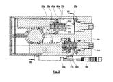
- Fig. 1 shows a vehicle door drive 1, in which a rack and pinion drive is formed with a gear 2, which meshes on opposite sides with rack parts 3, 4.
- the gear 2 is coupled in a known manner with at least one vehicle door, in particular via a rotatably coupled to the gear 2 rotary column 5 (s. Fig. 5 and 6 ).
- the rack and pinion parts 3, 4 are fluidically, in particular hydraulically, in actuating directions 8, 9 along piston-cylinder units 6, 7 acted upon parallel to each other actuated axes 10, 11 act, the piston-cylinder units 6, 7 generate actuating forces which parallel oriented to each other and have the same sense of direction.
- Fig. 1 shows a vehicle door drive 1, in which a rack and pinion drive is formed with a gear 2, which meshes on opposite sides with rack parts 3, 4.
- the gear 2 is coupled in a known manner with at least one vehicle door, in particular via a rotatably coupled to the gear 2 rotary column 5 (s. Fig. 5 and 6 ).
- the vehicle door drive 1 is formed with a housing 12 which is penetrated by two coaxial with the actuating axes 10, 11 oriented stepped bores 13, 14.
- the holes 13, 14 are formed substantially coincident, so that in the following only the geometry of a stepped bore is described, the corresponding applies to the other stepped bore 13, 14 applies.
- reference numerals for the bore 13 in the figures are marked with the additional letter a, while these are marked for the bore 14 with the additional letter b.
- the reference numerals are partially only in one of the holes 13, 14 and / or in one of FIGS. 1 and 2 entered.
- the bore 13 is formed with cylindrical sections, which in Fig. 1 be continuously extended from the right via steps to the left.
- the bore 13 forms a passage internal thread 15, which has a shoulder 16
- An end stop body 18 is formed in a rough approximation T-shaped, wherein a vertical leg of the T is equipped with an external thread, via which the Endanschlag stresses 18 can be screwed to the through-internal thread 15.
- the transverse leg of the T is under sealing, here by means of a sealing element inserted into a circumferential groove 19, sealing receiving in the cylindrical surface 17.
- the vertical leg of the T has in the outwardly projecting or externally accessible end region an engagement surface for a tool, in particular a cavity 20 with a suitable cross section for a polygonal tool.
- a tool in particular a cavity 20 with a suitable cross section for a polygonal tool.
- the cylindrical surface 17 merges into a further cylindrical surface 23, with which the housing 12 forms a cylinder 24 of the piston-cylinder unit 6 or 7.
- the pistons 25 are integrally formed by the rack parts 3, 4.
- the rack parts 3, 4 in the longitudinal section shown in a rough approximation L-shaped with a vertical leg 27 and a shorter horizontal leg 28.
- the two L are arranged horizontally, wherein the vertical legs 27 are oriented parallel to each other and parallel to the actuating axes 10, 11, while the horizontal legs 28 are directed towards each other in orientation parallel to each other.
- the horizontal leg 28 forms on the side facing away from the vertical leg 27, the piston 25 from.
- the vertical leg 27 form on the sides facing teeth 29, with which they mesh with a toothing 30 of the gear 2.
- On the opposite side of the teeth 29 of the vertical leg 27, these are slidably guided relative to the cylindrical surface 23, to which the cylindrical surface 23 may be at least partially coated or may be formed with a sleeve inserted into the housing 12 or a sliding member 31.
- spring and / or damping elements 32 may be arranged in the area of the pistons 25, which are used to approximate the toothed rack parts 3, 4 and thus also the vehicle doors to end positions, which have an open position or a closed position of the vehicle door correlate, the movement of the rack and pinion parts 3, 4 decelerate and / or limit.
- the spring and / or damping elements 32 are formed with an end cylindrical recess 33 of the piston 25.
- damping piston 34 are used, which are guided parallel to the actuating axes 10, 11.
- the damping piston 34 are formed in the longitudinal section shown U-shaped, wherein the U in Fig. 1 is arranged lying with opening in the direction of the recess 33.
- the vertical leg of the U are guided with their end regions under sealing by sealing elements 35 in the recess 33 slidably.
- a damping chamber 36 is limited, the volume of which changes with a relative movement of the damping piston 34 relative to the piston 25.
- the horizontal leg of the U of the damping piston 34 has a fürgangsaus Principleung 37, through which the damping chamber 36 is connected to a pressure chamber 38 of the piston-cylinder unit 6, 7, when the rack parts 3, 4 are in setting positions in which the damping piston 34 is not on the front side 21 of the Endanschlag stresses 18 rests.
- throttle cross section 39 which may be formed for example by a groove of the end face 21 abutting the damping piston 34 or by a transverse bore of the damping piston 34 .
- a prestressed compression spring 40 is arranged, one spring base of which is supported on the bottom of the recess 33, while the other spring base is supported on the damping piston 34.
- the damping piston 34 is spaced from the end face 21 of the Endantsch stressess 18, the compression spring 40 presses the damping piston 34 in a position with maximum damping volume of the damping chamber 36, this position is predetermined by a stop 41 between the damping piston 34 and piston 25.
- the effect of the spring and / or damping element 32 is as follows: Off the end positions, the damping piston 34 is spaced from the end face 21 of the Endantsch stressess 18, whereby the damping chamber 36 via the through-passage 37 fluidly with the pressure chamber 38 of the piston-cylinder unit 6, 7 is connected. Approaching an end position, an end face 42 of the damping piston 34 comes to bear against the end face 21 of the end stop body 18, whereby the passage recess 37 is at least partially closed. Further movement of the rack member 3, 4 in the direction of the end position requires compression of the compression spring 40, whereby by the compression spring 40 a adjustment-dependent braking force on the rack member 3, 4 is exercised.
- the movement towards the end position requires that fluid from the damping chamber 36 is displaced by the throttle cross-section 39, thus providing an additional braking force, which is preferably proportional to the speed.
- the end position can be achieved, for example, when the damping piston 34, preferably with the ends of the vertical leg of the U, comes to rest against the bottom of the recess 33.
- the rack parts 3, 4 together with the housing 12 and closure plates 43 define return spaces 44.
- the return spaces 44 are fluidly coupled to each other, so that in the opposite movement of the rack parts 3, 4 fluid from a rear space 44a in the other back space 44b (and vice versa) is "pushed".
- the holes 13, 14 are closed by cover 45 from the environment.
- a toothed rack part 3, 4 or piston 25 can be equipped with a sensor element 46 which is moved with the adjusting movement and which can cooperate with another sensor element 47 fixed to the housing.
- the sensor elements 46, 47 together form a sensor 48, which detects the adjusting movement of a toothed rack part 3.
- the sensor part 46 is formed with a permanent magnet, which cooperates with a responsive to the magnetic field of the permanent magnet sensor element 47.
- the sensor element 47 is arranged for the illustrated embodiment in a separate housing, which is attached to the housing 12 or flanged.
- the sensor 48 has a plug 49, by means of which a power supply of the sensor 48 can take place and / or a discharge of a signal of the sensor 48, for example to a control unit for controlling the vehicle drive 1, can be connected. It is also possible that the sensor 48 is designed as a reed sensor or contact.
- Fig. 1 shows the vehicle door drive 1 for approaching an end position for which the volume of the pressure chamber 38a is minimized while the volume of the pressure chamber 38b is maximized.
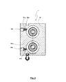
- Fig. 2 an approach to the other end position for which the volume of the pressure chamber 38b is minimized while the volume of the pressure chamber 38a is maximized.
- the vertical legs 27 of the L-shaped rack parts and the horizontal legs 28 form a rectangle with a recess 83 away from these legs 27, 28.
- the gear 2 is partially arranged.
- connection 50a, 50b which are fluidically connected to the pressure chambers 38 via throttles 51 and bores 52.
- Fig. 4 shows an alternative embodiment of the vehicle door drive 1, for which the spring and / or damping elements are formed without damping piston 34.
- the Endanschlagêtieri 18 has a extending into the pressure chamber 38 extension 53, which on the one hand to guide the compression spring 40 and the bondage of a Federfußyaks the compression spring 40 can serve and on the other hand can come with its front page for specifying an end stop to rest against the bottom of the recess 33.
- Fig. 5 shows an exemplary fluidic, in particular hydraulic control circuit for controlling the piston-cylinder units 6, 7 of a vehicle door drive 1.
- the pressure chambers 38 are connected via the associated throttles 51 with suction and pressure side connections of a reversible pump 54, so that depending on the drive direction of the Pump 54 fluid, in particular a hydraulic medium, from the pressure chamber 38a to the pressure chamber 38b and vice versa is conveyed.
- Fig. 6 shows an integration of two vehicle door drives 1a, 1b in an electro-hydraulic control circuit for the synchronous drive of two vehicle doors 65, 66, which are here each formed with two door wings, via associated rotary columns 5a, 5b.
- the control options the detection of the adjusting movement via sensors 67a, 67b, at least one manual valve 68, a supply of the pressure chambers via check valves 69, 70, the control of the check valves 69, 70 via control lines 71, 72, check valves 73rd , 74 for the purpose of replenishing leakage fluid from a supply 75, the control possibilities, the integration of a reversible pump 76, integration of a control unit 77 with supply of the signals of the sensors 67a, 67b, the activation of a drive unit 78 for the pump 76, the use of a single Pressure sensor 79 for detecting the pressure in the two admission paths using a shuttle valve 80 and other aspects is to the non-
- a fluidic, in particular hydraulic actuator 81 is formed.
- the two rack parts 3, 4 together form a fictitious "rack" 82, which serves to actuate the gear 2 in both directions and thus (with the above-mentioned additional advantages) causes the effect of a one-piece rack according to the prior art.
- the rack 82 is not designed as a one-piece rack, but this is formed with two relatively moved rack parts 3, 4.
Landscapes
- Engineering & Computer Science (AREA)
- Physics & Mathematics (AREA)
- Fluid Mechanics (AREA)
- Mechanical Engineering (AREA)
- General Engineering & Computer Science (AREA)
- Transmission Devices (AREA)
- Power-Operated Mechanisms For Wings (AREA)
Applications Claiming Priority (1)
| Application Number | Priority Date | Filing Date | Title |
|---|---|---|---|
| DE102012107522.0A DE102012107522B4 (de) | 2012-08-16 | 2012-08-16 | Fahrzeugtürantrieb mit Zahnstange |
Publications (2)
| Publication Number | Publication Date |
|---|---|
| EP2698547A2 true EP2698547A2 (fr) | 2014-02-19 |
| EP2698547A3 EP2698547A3 (fr) | 2016-01-20 |
Family
ID=48953331
Family Applications (1)
| Application Number | Title | Priority Date | Filing Date |
|---|---|---|---|
| EP13180112.8A Withdrawn EP2698547A3 (fr) | 2012-08-16 | 2013-08-12 | Entraînement de porte de véhicule à crémaillère |
Country Status (2)
| Country | Link |
|---|---|
| EP (1) | EP2698547A3 (fr) |
| DE (1) | DE102012107522B4 (fr) |
Cited By (9)
| Publication number | Priority date | Publication date | Assignee | Title |
|---|---|---|---|---|
| CN104564899A (zh) * | 2014-12-31 | 2015-04-29 | 中船重工中南装备有限责任公司 | 一种带弹簧缓冲的齿轮齿条缸 |
| EP3064696A1 (fr) | 2015-03-04 | 2016-09-07 | Reinhold Schulte | Entraînement de porte de véhicule pour un bus |
| CN108019478A (zh) * | 2017-12-29 | 2018-05-11 | 温州易得机械科技有限公司 | 一种横向推力装置 |
| CN113062894A (zh) * | 2021-03-16 | 2021-07-02 | 中煤科工集团重庆研究院有限公司 | 一种用于狭窄空间的摆动马达 |
| US11131134B2 (en) * | 2017-11-10 | 2021-09-28 | Tok, Inc. | Hinge arm damper mechanism |
| CN114199283A (zh) * | 2020-09-17 | 2022-03-18 | 费斯托股份两合公司 | 用于提供调节运动的调节装置 |
| CN115789005A (zh) * | 2022-11-22 | 2023-03-14 | 无锡福斯拓科科技有限公司 | 一种结构紧凑的高压驱动执行机构 |
| CN117468817A (zh) * | 2022-07-28 | 2024-01-30 | 李高恩 | 门用阻尼装置 |
| CN118363003A (zh) * | 2023-03-01 | 2024-07-19 | 深圳市银方加博科技有限公司 | 一种带精密基座的激光感应器 |
Families Citing this family (2)
| Publication number | Priority date | Publication date | Assignee | Title |
|---|---|---|---|---|
| ES2781467T3 (es) | 2017-05-26 | 2020-09-02 | Reinhold Schulte | Módulo de accionamiento hidráulico para una puerta de vehículo o un portón de vehículo |
| ES2764712T3 (es) | 2017-09-08 | 2020-06-04 | Reinhold Schulte | Grupo constructivo motriz de puerta de vehículo |
Citations (2)
| Publication number | Priority date | Publication date | Assignee | Title |
|---|---|---|---|---|
| DE599780C (de) | 1933-01-18 | 1934-07-09 | Magistrat Der Stadt Frankfurt | Antriebsvorrichtung zum OEffnen und Schliessen einer Tuer |
| DE102010002625A1 (de) | 2010-03-05 | 2011-11-17 | Reinhold Schulte | Hydraulische Stelleinrichtung für einen Türflügel eines Omnibusses |
Family Cites Families (5)
| Publication number | Priority date | Publication date | Assignee | Title |
|---|---|---|---|---|
| JPH01295008A (ja) * | 1988-05-20 | 1989-11-28 | Mitsubishi Electric Corp | ロータリアクチユエータ |
| JP2000018210A (ja) * | 1998-06-29 | 2000-01-18 | Ckd Corp | ラックピニオン型ロータリアクチュエータ |
| EP1826418A1 (fr) * | 2006-02-28 | 2007-08-29 | Afag Automation AG | Actionneur fluidique |
| DE102007017418B4 (de) * | 2007-04-13 | 2010-04-01 | Festo Ag & Co. Kg | Fluidbetätigte Drehantriebsvorrichtung |
| US8567752B2 (en) * | 2009-09-02 | 2013-10-29 | Emerson Process Management, Valve Automation Inc. | Rotary valve actuators having partial stroke damping apparatus |
-
2012
- 2012-08-16 DE DE102012107522.0A patent/DE102012107522B4/de active Active
-
2013
- 2013-08-12 EP EP13180112.8A patent/EP2698547A3/fr not_active Withdrawn
Patent Citations (2)
| Publication number | Priority date | Publication date | Assignee | Title |
|---|---|---|---|---|
| DE599780C (de) | 1933-01-18 | 1934-07-09 | Magistrat Der Stadt Frankfurt | Antriebsvorrichtung zum OEffnen und Schliessen einer Tuer |
| DE102010002625A1 (de) | 2010-03-05 | 2011-11-17 | Reinhold Schulte | Hydraulische Stelleinrichtung für einen Türflügel eines Omnibusses |
Cited By (10)
| Publication number | Priority date | Publication date | Assignee | Title |
|---|---|---|---|---|
| CN104564899A (zh) * | 2014-12-31 | 2015-04-29 | 中船重工中南装备有限责任公司 | 一种带弹簧缓冲的齿轮齿条缸 |
| EP3064696A1 (fr) | 2015-03-04 | 2016-09-07 | Reinhold Schulte | Entraînement de porte de véhicule pour un bus |
| US11131134B2 (en) * | 2017-11-10 | 2021-09-28 | Tok, Inc. | Hinge arm damper mechanism |
| CN108019478A (zh) * | 2017-12-29 | 2018-05-11 | 温州易得机械科技有限公司 | 一种横向推力装置 |
| CN114199283A (zh) * | 2020-09-17 | 2022-03-18 | 费斯托股份两合公司 | 用于提供调节运动的调节装置 |
| CN113062894A (zh) * | 2021-03-16 | 2021-07-02 | 中煤科工集团重庆研究院有限公司 | 一种用于狭窄空间的摆动马达 |
| CN113062894B (zh) * | 2021-03-16 | 2022-07-15 | 中煤科工集团重庆研究院有限公司 | 一种用于狭窄空间的摆动马达 |
| CN117468817A (zh) * | 2022-07-28 | 2024-01-30 | 李高恩 | 门用阻尼装置 |
| CN115789005A (zh) * | 2022-11-22 | 2023-03-14 | 无锡福斯拓科科技有限公司 | 一种结构紧凑的高压驱动执行机构 |
| CN118363003A (zh) * | 2023-03-01 | 2024-07-19 | 深圳市银方加博科技有限公司 | 一种带精密基座的激光感应器 |
Also Published As
| Publication number | Publication date |
|---|---|
| DE102012107522A1 (de) | 2014-06-05 |
| DE102012107522B4 (de) | 2015-09-24 |
| EP2698547A3 (fr) | 2016-01-20 |
Similar Documents
| Publication | Publication Date | Title |
|---|---|---|
| DE102012107522B4 (de) | Fahrzeugtürantrieb mit Zahnstange | |
| DE102010002625B4 (de) | Hydraulische Stelleinrichtung für einen Türflügel eines Omnibusses | |
| DE102011001003B4 (de) | Fahrzeugtür-Steuerkreis | |
| DE2240649C3 (de) | Steuerventil für eine Hilfskraftlenkung | |
| DE10202374A1 (de) | Zweiplatten-Schließsystem einer Spritzgießmaschine | |
| DE102012103638A1 (de) | Fluidischer Fahrzeugtür-Schwenkantrieb | |
| DE2339725A1 (de) | Hydraulische oder pneumatische zylinder-kolben-einrichtung | |
| DE102009049246A1 (de) | Kupplungspedalkraftunterstützungseinrichtung | |
| DE19543237C2 (de) | Hydraulische Stellvorrichtung, insbesondere Schwenkantrieb | |
| DE10361085B4 (de) | Hydraulisch-mechanische Schließfolgeregelung | |
| EP3406837B1 (fr) | Module hydraulique pour une porte de véhicule ou capot de véhicule | |
| DE202020102189U1 (de) | Busgepäckklappen-Antriebsbaugruppe, Nachrüstsatz oder Bausatz, Bus und Gruppe von Busgepäckklappeneinheiten | |
| EP1247995B1 (fr) | Elément hydraulique linéaire coulissant | |
| WO2006106070A1 (fr) | Dispositif d'amortissement pour entrainements lineaires | |
| DE2508268C3 (de) | Steuerkolben fur hydraulische Druckmittelfolgesteuerungen, insbesondere für ein Lenkventil einer Servolenkeinrichtung von Fahrzeugen | |
| DE3143040A1 (de) | Einrichtung zum arretieren eines druckmittelbetaetigten doppeltwirkenden kolbenzylinderantriebes | |
| DE19524777B4 (de) | Türschließer mit einstellbarer Vorspannung einer Schließerfeder | |
| EP3338909B1 (fr) | Dispositif d'estampage | |
| EP1739264B1 (fr) | Valve pour le contrôle d'entraînement d'un battant de porte ou de fenêtre | |
| DE10154465A1 (de) | Schließeinheit für eine Kunststoffverarbeitungsmaschine | |
| EP1620626B2 (fr) | Sequence de fermeture mecano-hydraulique | |
| DE102007029579A1 (de) | Elektrisch ansteuerbare Baugruppe mit einem Hydraulikanschluss | |
| DE19524778B4 (de) | Türschließer mit einem Verdrängerkolben | |
| DE102011078397B3 (de) | Antrieb zum Öffnen und/oder Schließen eines beweglichen Flügels einer Tür oder eines Fensters | |
| DE102008043246A1 (de) | Hyraulische Servolenkung |
Legal Events
| Date | Code | Title | Description |
|---|---|---|---|
| AK | Designated contracting states |
Kind code of ref document: A2 Designated state(s): AL AT BE BG CH CY CZ DE DK EE ES FI FR GB GR HR HU IE IS IT LI LT LU LV MC MK MT NL NO PL PT RO RS SE SI SK SM TR |
|
| AX | Request for extension of the european patent |
Extension state: BA ME |
|
| PUAI | Public reference made under article 153(3) epc to a published international application that has entered the european phase |
Free format text: ORIGINAL CODE: 0009012 |
|
| PUAL | Search report despatched |
Free format text: ORIGINAL CODE: 0009013 |
|
| AK | Designated contracting states |
Kind code of ref document: A3 Designated state(s): AL AT BE BG CH CY CZ DE DK EE ES FI FR GB GR HR HU IE IS IT LI LT LU LV MC MK MT NL NO PL PT RO RS SE SI SK SM TR |
|
| AX | Request for extension of the european patent |
Extension state: BA ME |
|
| RIC1 | Information provided on ipc code assigned before grant |
Ipc: F15B 15/22 20060101ALI20151214BHEP Ipc: E05F 15/04 00000000ALI20151214BHEP Ipc: F15B 15/06 20060101AFI20151214BHEP |
|
| STAA | Information on the status of an ep patent application or granted ep patent |
Free format text: STATUS: THE APPLICATION IS DEEMED TO BE WITHDRAWN |
|
| 18D | Application deemed to be withdrawn |
Effective date: 20160721 |