EP2698574B1 - Anschlussstück für Verbindungsrohre eines Klimaanlagensystems, und entsprechendes Klimaanlagengerät - Google Patents
Anschlussstück für Verbindungsrohre eines Klimaanlagensystems, und entsprechendes Klimaanlagengerät Download PDFInfo
- Publication number
- EP2698574B1 EP2698574B1 EP13179379.6A EP13179379A EP2698574B1 EP 2698574 B1 EP2698574 B1 EP 2698574B1 EP 13179379 A EP13179379 A EP 13179379A EP 2698574 B1 EP2698574 B1 EP 2698574B1
- Authority
- EP
- European Patent Office
- Prior art keywords
- connector
- piston
- longitudinal body
- stiffness
- sleeve
- Prior art date
- Legal status (The legal status is an assumption and is not a legal conclusion. Google has not performed a legal analysis and makes no representation as to the accuracy of the status listed.)
- Active
Links
Images

Classifications
-
- F—MECHANICAL ENGINEERING; LIGHTING; HEATING; WEAPONS; BLASTING
- F16—ENGINEERING ELEMENTS AND UNITS; GENERAL MEASURES FOR PRODUCING AND MAINTAINING EFFECTIVE FUNCTIONING OF MACHINES OR INSTALLATIONS; THERMAL INSULATION IN GENERAL
- F16L—PIPES; JOINTS OR FITTINGS FOR PIPES; SUPPORTS FOR PIPES, CABLES OR PROTECTIVE TUBING; MEANS FOR THERMAL INSULATION IN GENERAL
- F16L29/00—Joints with fluid cut-off means
- F16L29/04—Joints with fluid cut-off means with a cut-off device in each of the two pipe ends, the cut-off devices being automatically opened when the coupling is applied
Definitions
- the invention relates to a connector for connecting the pipes of an air conditioning system, these pipes being able to connect various air conditioning units of said system.
- the invention will find its use for hermetic interconnection under pressure during the assembly of air conditioning apparatus, in particular for air conditioning apparatus of the two-block wall type.
- Such an air conditioning system comprises an indoor unit and at least one outdoor unit connected together by connecting pipes.
- a conventional method for installing an air conditioner in order to expel air from the indoor unit and air into the connection pipes after installation, is to charge the main part of the outdoor unit with refrigerant gas. to a volume in excess of the specified volume required for use of the system air conditioning function.
- This excess of refrigerant gas makes it possible to purge the air present in the rest of the circuit.
- a two-way valve is used at the outdoor unit so that, once the installation is complete, the circulation of the refrigerant gas expels the air into the atmosphere.
- This traditional process is particularly damaging to the environment since it induces a degassing of refrigerant gas in the particularly harmful atmosphere, in particular by the destruction of the ozone layer.
- the problem underlying the present invention is to allow the positioning of a connector in an air conditioning circuit which, on the one hand, is both a hermetic closure until its final connection while being able to be easily put in definitive connection position and, secondly, which is such that successive connections do not alter the internal elements it contains.
- the present invention relates to an air conditioning pipe connector comprising a first portion and a second portion adapted to cooperate so that the connector is alternately in a connected position or a disconnected position, the first portion comprising a first body longitudinal passage providing a through passage receiving a movable valve, said passage housing a first spring for maintaining the valve in sealing contact with the first longitudinal body when the connector is in the disconnected position, the longitudinal body comprising an internal stop against which the valve is intended to be in default contact under the action of a first spring at least when the connector is in the disconnected position and the second part comprising a second longitudinal body forming a through passage and a movable sleeve and a piston, the piston being placed at least partially in s the sleeve placed at least partially in the second longitudinal body and the piston being fixed relative to the second longitudinal body by means of a retaining ring on which the piston is fixed, a second spring being placed between the retaining ring and the sleeve in the second longitudinal body so as to maintain contact against the internal stop
- the sum of the stiffness of the two springs is between 18 and 40 newtons per millimeter.
- the springs are thus constituted so as to be neither easily actuable when the connector is in the disconnected position nor too difficult to couple when the connector is in the connected position.
- the technical effect is to be able to hermetically close the two parts of the connector until its final connection.
- a stiffness between 18 and 40 N / mm
- the piston and the valve are difficult to actuate inadvertently ensuring a perfect seal while allowing not to make it too difficult to mount the connector for the circulation of gas passing through the valve. connector.
- substantially identical spring stiffness in the two parts of the connector there is a distribution of equivalent pressures for the two parts of the connector and therefore a uniform stress of the elements present in the connector as the seals.
- identical or substantially identical is meant that the stiffness of the springs is equivalent to the tolerances of measurement and manufacture.
- the invention also relates to an air conditioning apparatus comprising an outdoor unit and at least one indoor unit, the outer and inner units respectively having an external circuit filled with a refrigerant or an internal circuit, the two circuits being connected by such a connector. .
- two connecting pipes respectively connect the input of the external circuit of the outdoor unit to the output of the internal circuit of the indoor unit or the output of the external circuit of the outdoor unit to the input of the internal circuit of the indoor unit.
- indoor unit a connector being provided at each end of each pipe.
- each connector has one of its longitudinal bodies comprising the spring with the lowest stiffness disposed on the side of the indoor or outdoor unit while the other longitudinal body comprising the spring with the highest stiffness is disposed on the side of the connecting pipe.
- Pipe means a pipe or conduit which may be flexible or rigid and intended for the flow of a fluid, for example a liquid or a gas.
- These pipes may be fluid circulation elements being connected to indoor and outdoor units forming an air conditioning unit.
- the connector according to the invention comprises a first part 1 preferably intended to be connected to an outdoor unit 16 of an air conditioning unit and a second part 2 which can be intended to be connected to an indoor unit 17 of an air conditioning unit, but this is not obligatory.
- the connectors are positioned in an air conditioning apparatus according to the stiffnesses presented by the springs respectively housed in the first and second parts, as will be explained later, in particular with regard to the figure 12 .
- the first part 1 and the second part 2 are intended to cooperate so as to allow the connection of the pipes to which they are attached.
- the connector When the first part 1 and the second part 2 are connected, the connector is in the connected position. Conversely, when the first part 1 and the second part 2 are disconnected, the connector is in the disconnected position.
- disconnected position is meant that the first part 1 and the second part 2 of the connector are not connected. There is no fluid passage through the connector.
- connected position means that the first part 1 and the second part 2 of the connector are connected whether or not there is possibility of passage of the fluid.
- the first part 1 comprises a first longitudinal body 3 forming a through passage for the flow of the fluid.
- the first longitudinal body 3 comprises in the through passage a movable valve 5 closed by default.
- the valve 5 is provided with at least one sealing means 7 sealing by default with the first longitudinal body 3 at least when the connector is in the disconnected position.
- the first longitudinal body 3 comprises an internal stop 11 against which the valve 5 is intended to be in contact by default.
- the valve 5 is kept closed by default by means of a first elastic element such as a spring 14 disposed between the valve 5 and preferably the first longitudinal body 3.
- a first elastic element such as a spring 14 disposed between the valve 5 and preferably the first longitudinal body 3.
- the internal stop 11 is formed in the first longitudinal body 3 in its proximal portion 20, that is to say at the end intended to be connected to the second portion 2 of the connector.
- the proximal end of the second part 2 is the one intended to be connected to the first part 1.
- the valve 5 comprises a head on which are positioned sealing means 7 which are in default contact with the distal surface of the internal abutment 11, preferably by means of the first spring 14 disposed at the stem of the valve 5.
- the distal surface of the inner abutment 11 is constituted by the surface facing the distal end of the first portion 1.
- the sealing means 7 exerts an axial support oriented along the longitudinal axis of the valve 5 on the internal abutment 11.
- the second part 2 of the connector comprises a second longitudinal body 4 providing a through passage for the flow of fluid.
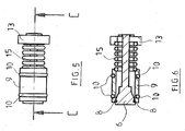
- a movable sleeve 9 In the through passage is placed a movable sleeve 9 and a piston 6.
- the sleeve 9 is advantageously placed at least partially in the second longitudinal body 4 and receives the piston 6 in its interior.
- the piston 6 is provided with at least one sealing means 8 sealing by default with the sleeve 9.
- this sealing is performed at the proximal end of the second portion 2.
- This means of sealing 8 is preferably an O-ring arranged on the piston 6.
- This sealing means 8 is more precisely placed on the conical head of the piston 6 so as to cooperate with the proximal end of the sleeve 9.
- the sleeve 9 advantageously has the a level of its proximal end a beveled surface towards the inside of the sleeve intended to cooperate with the conical head of the piston 6.
- the support of the sealing means 8 on the sleeve 9 is a composite bearing comprising an axial component and a radial component .
- the sleeve 9 comprises at least two seals 10. At least one seal 10 is intended to seal by default between the second longitudinal body 4 and the sleeve 9. At least one other seal 10 is meanwhile intended to seal with the first longitudinal body 3 when the first part 1 and the second part 2 are connected. According to a preferred possibility, the seals 10 are O-rings.
- the second part 2 is hermetic and does not allow the output of the refrigerant gas, for example outside an indoor unit 17 of the air conditioning unit.
- the piston 6 and the internal stop 11 are configured not to come into contact.
- the piston 6 is configured to cooperate with the valve 5.
- the piston 6 has a smaller diameter than the passage formed by the internal stop 11.
- the sleeve 9 is configured to come into contact with the internal stop 11.
- the piston 6 is fixedly mounted on the second longitudinal body 4 preferably by means of a retaining ring 13.
- the piston rod 6 is fixedly mounted at the retaining ring 13.
- the retaining ring 13 is placed at the level of the distal end of the second part 2.
- the positioning of the piston 6 can be controlled according to the positioning of the retaining ring 13.
- the retaining ring 13 constitutes a stop for a second elastic element such as a spring 15 intended to be positioned between the retaining ring 13 and the sleeve 9 so as to maintain the sleeve 9 partially outside the second longitudinal body 4.
- a second elastic element such as a spring 15 intended to be positioned between the retaining ring 13 and the sleeve 9 so as to maintain the sleeve 9 partially outside the second longitudinal body 4.
- the stiffnesses of the first and second springs 14, 15 are substantially identical or with a difference of less than 4 newtons per millimeter so as to have a balanced system.
- the sum of the stiffness of the two springs is between 18 and 40 newtons per millimeter. This allows the springs 14, 15 to be neither easily actuable, when the connector is in the disconnected position, nor too difficult to couple, when the connected position of the connector.
- the connector according to the invention advantageously comprises a clamping means 12 carried by one of the first and second parts 1, 2 cooperating with a complementary means carried by the other of the first or second parts 1, 2.
- the clamping means 12 and its complementary means allow, when connecting the first part 1 and the second part 2, to bring them together and keep them in position. According to a preferred possibility, the approximation is progressive.
- the clamping means 12 and its complementary means consist of elements male / female thread.
- the first part 1 has an end intended to be vis-à-vis the second part 2 which comprises an external thread 12a, the outer thread 12a illustrating the complementary means.
- the second part 2 comprises a clamping means advantageously in the form of a retaining ring 12 which can be screwed onto the outer thread 12a present at the end of the first part 1.
- the external thread 12a has a diameter D which can vary between 20 and 25 mm, as well as a total length L that can vary from 13 to 16 mm.
- Such an external thread 12a may comprise 7 to 10 threads with a pitch P of 1.5 mm.
- the first spring 14 cooperating with the valve 5 in the longitudinal body 3 of the first part 1 may have a stiffness of 8.4 N per millimeter while the second spring 15 surrounding the piston 6 in the longitudinal body 4 of the second part 2 has a stiffness of 11.7 N per millimeter, which gives a sum of the stiffness of the two springs 14 and 15 equal to 20.2 and a stiffness deviation of 3.3.
- first spring 14 of the longitudinal body 3 of the first portion 1 has a stiffness of 18 N per millimeter while the second spring 15 of the longitudinal body 4 of the second portion has a stiffness of 16.7 N per millimeter, which gives a sum of the stiffness of the two springs 14 and 15 equal to 34.7 and a stiffness deviation of 3.3.
- first spring 14 of the longitudinal body 3 of the first portion 1 has a stiffness of 8.4 N per millimeter while the second spring 15 of the longitudinal body 4 of the second portion has a stiffness of 11, 2 N per millimeter, which gives a sum of the stiffness of the two springs 14 and 15 equal to 19.6 and a stiffness deviation of 2.8.
- each spring 14, 15 may for example be between 7 and 22 N / mm with a selection of stiffness values of each spring respectively of the first and the second part or conversely to 7 and 11 N. / mm and a selection of stiffness values each spring respectively of the first and the second part or conversely 18 and 22 N / mm.
- the ratio of the stiffness difference to the sum of the stiffness can vary from 0 to 0.22. This ratio is advantageously between 0 and 0.1 so that the two springs 14 and 15 are not too easily actuated when the connector is disassembled.
- the method of mounting the first and second parts 1, 2 comprises the following steps.
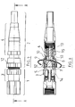
- the respective threading means 12, 12a of the first and second parts 1, 2 are placed in cooperation and screwed in progressively, which starts, for example, for a thread length, remaining and not in engagement, equal to 12.4 mm or 12, 3 mm for threads with a total length of 14 mm. Beyond a certain depth of screwing, leaving for example a thread, remaining and not in engagement, from 7.5 to 7.7 mm, the piston 6 bears on the valve 5. Similarly, the sleeve 9 comes into contact with the internal stop 11.
- the sleeve 9 comes into contact with its proximal end with the proximal surface of the internal abutment 11.
- the tightening depth of the clamping means 12 is not sufficient and, as a result, the valve 5 and the piston 6 are always closed by default.
- the sleeve 9 is at least one of its seals 10 capable of sealing with the first part 1.
- Figures 7 and 8 the fluid flow does not yet circulate between the first part 1 and the second part 2 of the connector.
- the seal between the first part 1 and the second part 2 is already achieved by the sleeve 9.
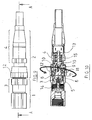
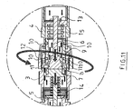
- the piston 6 By continuing the tightening of the clamping means 12 on its complementary means, the piston 6 generates a recoil movement of the valve 5 direction of the distal end of the first part 1 thus eliminating the seal between the valve 5 and the internal stop 11. Likewise, this movement moves the piston 6 and the sleeve 9 away and removes the seal between the piston 6 and the sleeve 9.
- This step is represented in Figures 9 to 11 . There is therefore circulation of the fluid between the first part 1 and the second part 2 while having a perfect seal between the first part 1 and the second part 2 thanks to the sleeve 9 and its joints 10. During this step, the sleeve 9 and the valve 5 have a displacement in opposite direction.
- the end of the first part 1 has, for example, a non-engaged thread varying from 2.5 mm to 2.75 mm.
- the provision of the present invention makes it possible, when the tightening means 12 are screwed, to maintain constantly the seal between the first part 1 and the second part 2 because of the simultaneous displacement of the sleeve 9, constituent element of the second part 2 and the first part 1. Indeed, the support between the inner abutment 11 and the sleeve 9 is constant and perpetual when the tightening means 12 is screwed with its complementary means 12a.
- This advantage is due in particular to the stiffness of the springs 14-15 studied to have a balanced system.
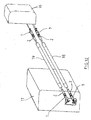
- the figure 12 gives an example of mounting an air conditioning unit comprising the connector according to the invention.
- An air conditioning apparatus according to the invention comprises at least one outdoor unit 16 intended to be positioned outside the volume to be conditioned.
- the outdoor unit 16 comprises forced convection means having a fan and a circuit, said external circuit, in which circulates a refrigerant.
- connectors are generally arranged so as to ensure the closure of the circuit during the phases of assembly and disassembly.
- the apparatus comprises, on the other hand, an indoor unit 17, for example consisting of a wall block adapted to blow air at the selected temperature in the volume to be air conditioned.
- the indoor unit 17 has an internal circuit for the circulation of the refrigerant fluid.
- the inner and outer circuits respectively of the indoor unit 17 and the outdoor unit 16, each having an input and a circuit output, are respectively connected by one of the connection pipes 18, 19 also illustrated in FIG. figure 12 .
- the ends of the connecting pipes 18, 19 are secured to the second portion 2 of a respective connector according to the invention.
- the first part 1 of the connector according to the invention is then respectively mounted on the outdoor unit 16 and the indoor unit 17. This is not necessarily the case in all embodiments of the invention.
- two connecting pipes 18, 19 respectively connect the input of the external circuit of the outdoor unit 16 to the output of the internal circuit of the indoor unit 17 or the output of the external circuit of the the outdoor unit 16 at the inlet of the inner circuit of the indoor unit 17, a connector being provided at each end of each pipe 18, 19.
- each connector has one of its respective longitudinal bodies for the first and second parts 1, 2 comprising the spring with the lowest stiffness disposed on the side of the indoor unit 17 or outer 16 while the other longitudinal body of the first or second part 1, 2 comprising the spring with the highest stiffness is arranged on the side of the connecting pipe 18, 19.
- the connector according to the invention makes it possible to avoid any manipulation of the refrigerant fluid on machines preloaded with fluid (the fluid is contained in the compressor of the outdoor unit 16) and avoids commissioning which consists in the extraction of the fluid , vacuum drawing and reintroduction of the fluid. It is therefore prohibited any risk of degassing or leakage due to improper handling or a lack of equipment.
Landscapes
- Engineering & Computer Science (AREA)
- General Engineering & Computer Science (AREA)
- Mechanical Engineering (AREA)
- Quick-Acting Or Multi-Walled Pipe Joints (AREA)
Claims (15)
- Anschlussstück für den Schlauch eines Klimakreislaufes mit einen ersten Teil (1) und einen zweiten Teil (2), die dazu bestimmt sind, so zusammenzuwirken, dass sich das Anschlussstück abwechselnd in einer angeschlossenen und einer nicht angeschlossenen Position befindet, wobei der erste Teil (1) einen ersten langgestreckten Körper (3) umfasst, der einen Durchgang bildet, in den ein bewegliches Ventil (5) positioniert wird, wobei im Durchgang eine erste Feder (14) aufgenommen wird, die dazu bestimmt ist, das Ventil (5) in dichtem Kontakt zum ersten längsgestreckten Körper (3) zu halten, wenn das Anschlussstück nicht angeschlossen ist, wobei der längsgestreckte Körper einen Innenanschlag (11) aufweist, mit dem das Ventil (5) zumindest unter Einwirkung der ersten Feder (14) in standardmäßigem Kontakt steht, wenn das Anschlussstück nicht angeschlossen ist, und der zweite Teil (2) einen zweiten längsgestreckten Körper (4), der einen Durchgang bildet, sowie eine bewegliche Muffe (9) und einen Kolben (6) aufweist, wobei der Kolben (6) mindestens teilweise in der Muffe (9), die sich zumindest teilweise im zweiten längsgestreckten Körper (4) befindet, positioniert ist, und der Kolben (6) im Verhältnis zum zweiten längsgestreckten Körper (4) durch einen Haltering (13), auf dem der Kolben (6) befestigt ist, feststehend ist, wobei eine zweite Feder (15) zwischen dem Haltering (13) und der Muffe (9) so im zweiten längsgestreckten Körper positioniert wird, dass die Muffe (9) in Kontakt mit dem Innenanschlag (11) des ersten längsgestreckten Körpers (3) gehalten wird, wenn sich das Anschlussstück in angeschlossener Position befindet, wobei besagtes Anschlussstück dadurch gekennzeichnet ist, dass die Federkonstanten der ersten und der zweiten Feder (14, 15) identisch sind oder weniger als 4 Newton pro Millimeter voneinander abweichen, so dass ein ausgewogenes System entsteht und die Summe der Federkonstanten der beiden Federn bei 18 bis 40 Newton pro Millimeter liegt.
- Anschlussstück nach dem vorhergehenden Anspruch, bei dem die Konstanten der Federn (14, 15) jeweils zwischen 7 und 22 N/mm betragen, wobei für eine der Federn (14, 15) Federkonstanten zwischen 7 und 11 N/mm, und für die andere der beiden Federn (14, 15) Federkonstanten zwischen 18 und 22 N/mm ausgewählt werden können.
- Anschlussstück nach einem der zwei vorhergehenden Ansprüche, bei denen das Verhältnis der Abweichung der Federkonstanten zwischen der ersten und der zweiten Feder (14, 15) in Bezug auf die Summe der Federkonstanten der ersten und der zweiten Feder (14, 15) zwischen 0 und 0,22 liegt.
- Anschlussstück nach dem vorhergehenden Anspruch, bei dem das Verhältnis zwischen 0 und 0,1 liegt.
- Anschlussstück nach einem der vorhergehenden Ansprüche, bei dem ein erster (1) oder ein zweiter (2) Teil ein Außengewinde (12a) aufweist, auf welches ein Spannmittel (12) aufgeschraubt wird, das von dem zweiten (2) oder ersten (1) Teil getragen wird.
- Anschlussstück nach dem vorhergehenden Anspruch, bei dem das Außengewinde (12a) 7 bis 10 Rippen, einen Außendurchmesser von 20 bis 25 mm und eine Gesamtlänge von 14 bis 15 mm aufweist.
- Anschlussstück nach einem der zwei vorhergehenden Ansprüche, bei dem das Spannmittel die Form eines Ringes (12) aufweist, in dem das Gewinde des ersten (1) oder des zweiten (1) Teils aufgenommen wird.
- Anschlussstück nach dem vorhergehenden Anspruch, bei dem der Ring vom zweiten Teil (2) getragen wird, wobei das Außengewinde (12a) des Anschlussstücks vom Ende des ersten, während der Montage gegenüber dem zweiten Teil (2) liegenden Teils (1) getragen wird.
- Anschlussstück nach einem der vier vorhergehenden Ansprüche, bei dem das Spannen des Spannmittels (12) durch Schub des Kolbens dazu führt, dass sich das Ventil (5) im Verhältnis zum ersten längsgestreckten Körper (3) verschiebt, die Dichtheit des Ventils (5) somit aufgehoben wird und durch das Verschieben der Muffe (9) im Verhältnis zum Kolben (6) die Dichtheit zwischen Kolben (6) und Muffe aufgehoben wird und somit die Zirkulation des Stroms zwischen dem ersten (1) und dem zweiten Teil (2) möglich ist.
- Anschlussstück nach einem der vorhergehenden Ansprüche, bei dem das Ventil (5) mit mindestens einem Dichtmittel (7) versehen ist, welches in Bezug auf den ersten längsgestreckten Körper (3) in der angeschlossenen Position zumindest eine standardmäßige Dichtheit gewährleistet.
- Anschlussstück nach dem vorhergehenden Anspruch, in dem zumindest der Kolben (6) mit mindestens einem Dichtmittel (8) versehen ist, welches die standardmäßige Dichtheit gegenüber der Muffe (9) gewährleistet, wobei die Muffe (9) mindestens zwei Dichtungen (10) aufweist, von denen mindestens eine dazu bestimmt ist, die dauerhafte Dichte zum zweiten längsgestreckten Gehäuse (4) zu gewährleisten, und mindestens die andere dazu bestimmt ist, die Dichtheit gegenüber dem ersten längsgestreckten Körper (3) zu gewährleisten, wenn sich das Anschlussstück in angeschlossener Position befindet,
- Anschlussstück nach einem der vorhergehenden Ansprüche, in dem der Kolben (6) so angeordnet ist, dass er in Kontakt mit dem Ventil (5) steht, wenn sich das Anschlussstück in angeschlossener Position befindet.
- Klimagerät mit einer Außeneinheit (16) und mindestens einer Inneneinheit (17), wobei die Außeneinheit (16) und Inneneinheit (17) jeweils einen inneren Kältemittelkreislauf oder einen äußeren Kreislauf umfassen, wobei die beiden Kreisläufe nach einem der vorhergehenden Ansprüche durch ein Anschlussstück miteinander verbunden sind.
- Klimagerät nach dem vorhergehenden Ansprüche, bei dem zwei Anschlussschläuche (18, 19) jeweils den Eintritt des äußeren Kreislaufes der Außeneinheit (16) mit dem Austritt des inneren Kreislaufes der Inneneinheit (17) oder den Austritt des äußeren Kreislaufs der Außeneinheit (16) mit dem Eintritt des inneren Kreislaufs der Inneneinheit (17) verbinden, wobei für jedes Ende eines jeden Schlauchs (18, 19) ein Anschlussstück vorgesehen ist.
- Klimagerät nach dem vorhergehenden Anspruch, wobei jedes Anschlussstück einen längsgestreckten Körper (3, 4) an der Seite der Inneneinheit (17) oder Außeneinheit (16) umfasst, dessen Feder (14, 15) die geringste Federkonstante aufweist, und einen anderen längsgestreckten Körper (4, 3) an der Seite des Anschlussschlauchs (18, 19), dessen Feder (15, 14) die höchste Federkonstante aufweist.
Applications Claiming Priority (1)
| Application Number | Priority Date | Filing Date | Title |
|---|---|---|---|
| FR1257825A FR2994592B1 (fr) | 2012-08-16 | 2012-08-16 | Connecteur pour tuyaux de raccordement de systeme de climatisation et appareil de climatisation associe |
Publications (2)
| Publication Number | Publication Date |
|---|---|
| EP2698574A1 EP2698574A1 (de) | 2014-02-19 |
| EP2698574B1 true EP2698574B1 (de) | 2016-10-05 |
Family
ID=46963969
Family Applications (1)
| Application Number | Title | Priority Date | Filing Date |
|---|---|---|---|
| EP13179379.6A Active EP2698574B1 (de) | 2012-08-16 | 2013-08-06 | Anschlussstück für Verbindungsrohre eines Klimaanlagensystems, und entsprechendes Klimaanlagengerät |
Country Status (3)
| Country | Link |
|---|---|
| EP (1) | EP2698574B1 (de) |
| ES (1) | ES2609878T3 (de) |
| FR (1) | FR2994592B1 (de) |
Families Citing this family (13)
| Publication number | Priority date | Publication date | Assignee | Title |
|---|---|---|---|---|
| FR3033019B1 (fr) | 2015-02-19 | 2017-10-06 | Star Light | Connecteur pour tuyaux de raccordement de systeme de climatisation et appareil de climatisation associe |
| GB2538310A (en) * | 2015-05-15 | 2016-11-16 | New Widetech Ind Co Ltd | Water-seal connector and an air-conditioning device with the same |
| CN105508776B (zh) * | 2016-01-11 | 2018-01-12 | 东方电气集团东方电机有限公司 | 一种油路连通方法 |
| CN105715892B (zh) * | 2016-05-05 | 2019-03-29 | 徐工集团工程机械股份有限公司 | 一种有限压功能的快速接头 |
| FR3051239B1 (fr) * | 2016-05-12 | 2018-04-20 | Star Light | Connecteur pour tuyaux de raccordement de systeme de climatisation et appareil de climatisation associe |
| CN105972361B (zh) * | 2016-07-19 | 2018-09-07 | 无锡市五十五度科技有限公司 | 一种液用高压快速接头 |
| US20200088417A1 (en) * | 2016-09-28 | 2020-03-19 | Jason Ingram | Apparatus and process for amateur ductless hvac installation |
| US11982451B1 (en) | 2016-09-28 | 2024-05-14 | Joi Holding Llc | Apparatus and process for amateur HVAC installation |
| US11125479B1 (en) | 2016-09-28 | 2021-09-21 | Joi Holding Llc | Apparatus and process for amateur HVAC installation |
| TWI639790B (zh) * | 2017-01-24 | 2018-11-01 | 中大冷凍材料股份有限公司 | 接頭的結構 |
| USD1010776S1 (en) | 2017-09-28 | 2024-01-09 | Joi Holding Llc | Female quick-connect connector |
| USD1008425S1 (en) | 2017-09-28 | 2023-12-19 | Joi Holding Llc | Male quick-connect connector |
| USD1008426S1 (en) | 2020-04-02 | 2023-12-19 | Joi Holding Llc | Quick-connect coupler |
Family Cites Families (5)
| Publication number | Priority date | Publication date | Assignee | Title |
|---|---|---|---|---|
| US3380476A (en) * | 1964-04-03 | 1968-04-30 | Purolator Products Inc | Fluid coupling with vacuum assisted valve elements |
| DE2262247A1 (de) | 1972-12-20 | 1974-06-27 | Teves Gmbh Alfred | Elektromagnetisches ventil |
| US3994317A (en) | 1974-07-31 | 1976-11-30 | Nitto Kohki Co., Ltd. | Pipe coupling |
| FR2831644B1 (fr) * | 2001-10-31 | 2005-04-29 | Delachaux Sa | Clapet automatique |
| EP2388501A1 (de) * | 2010-05-19 | 2011-11-23 | Star Light | Anschlussstück für Verbindungsrohre eines Klimaanlagensystems, und entsprechendes Klimaanlagengerät |
-
2012
- 2012-08-16 FR FR1257825A patent/FR2994592B1/fr active Active
-
2013
- 2013-08-06 ES ES13179379.6T patent/ES2609878T3/es active Active
- 2013-08-06 EP EP13179379.6A patent/EP2698574B1/de active Active
Also Published As
| Publication number | Publication date |
|---|---|
| EP2698574A1 (de) | 2014-02-19 |
| FR2994592A1 (fr) | 2014-02-21 |
| ES2609878T3 (es) | 2017-04-24 |
| FR2994592B1 (fr) | 2014-08-22 |
Similar Documents
| Publication | Publication Date | Title |
|---|---|---|
| EP2698574B1 (de) | Anschlussstück für Verbindungsrohre eines Klimaanlagensystems, und entsprechendes Klimaanlagengerät | |
| EP2388501A1 (de) | Anschlussstück für Verbindungsrohre eines Klimaanlagensystems, und entsprechendes Klimaanlagengerät | |
| FR2657138A1 (fr) | Partie de raccord rapide a organe de reduction de pression. | |
| EP2771598B1 (de) | Isolierventil | |
| CA2969308A1 (fr) | Element de raccord rapide avec organe de decharge et raccord rapide comprenant un tel element | |
| CH684955A5 (fr) | Vanne à tiroir et quatre voies. | |
| EP1085245A1 (de) | Verbindungsmittel für Anschliessen eines Rohres an röhrenförmigen Körper | |
| CA1261311A (fr) | Dispositif d'obturation pour conduite vehiculant un fluide | |
| EP3244112B1 (de) | Anschlussstück für verbindungsrohre eines klimaanlagensystems, und entsprechendes klimaanlagengerät | |
| FR2906014A1 (fr) | Appareil de climatisation et son procede d'installation | |
| EP3059483B1 (de) | Anschlussstück für verbindungsrohre eines klimaanlagensystems, und entsprechendes klimaanlagengerät | |
| WO2015145027A1 (fr) | Interface améliorée pour une vanne de conduit de fluide cryogenique. | |
| EP3204679B1 (de) | Kupplung zur kräuselung auf mindestens ein rohr, rohrsatz mit solch einer kupplung und verfahren zur montage eines rohres mit solch einer kupplung | |
| WO2026093085A1 (fr) | Connecteur de circuit de climatisation | |
| FR2820487A1 (fr) | Robinet trois voies pour prise en charge sur le cote ou le dessus | |
| FR2995655A1 (fr) | Raccord et procede pour raccorder manuellement une enveloppe souple a un conduit de gaz | |
| FR2649464A1 (fr) | Robinet a boisseau | |
| EP3393965B1 (de) | Ausrüstung mit einem einsetzbaren koaxialventil zur übertragung eines fluid in ein reservoir und verfahren | |
| FR2969737A1 (fr) | Dispositif et procede pour remplacer un tube definissant une portion de circuit de transport de fluide | |
| WO2007128895A1 (fr) | Raccord obturateur manuel sans fuite | |
| EP3277959B1 (de) | Peristaltische pumpe mit verbesserter rohrbefestigung | |
| FR2866409A3 (fr) | Raccord femelle pour conduite de fluide | |
| FR3087517A1 (fr) | Dispositif de raccordement pour realiser le piquage d'un tube sur une paroi de canalisation | |
| FR2908182A1 (fr) | Appareil de climatisation et son procede d'installation | |
| FR2649777A1 (fr) | Raccord etanche |
Legal Events
| Date | Code | Title | Description |
|---|---|---|---|
| AK | Designated contracting states |
Kind code of ref document: A1 Designated state(s): AL AT BE BG CH CY CZ DE DK EE ES FI FR GB GR HR HU IE IS IT LI LT LU LV MC MK MT NL NO PL PT RO RS SE SI SK SM TR |
|
| AX | Request for extension of the european patent |
Extension state: BA ME |
|
| PUAI | Public reference made under article 153(3) epc to a published international application that has entered the european phase |
Free format text: ORIGINAL CODE: 0009012 |
|
| 17P | Request for examination filed |
Effective date: 20140731 |
|
| RBV | Designated contracting states (corrected) |
Designated state(s): AL AT BE BG CH CY CZ DE DK EE ES FI FR GB GR HR HU IE IS IT LI LT LU LV MC MK MT NL NO PL PT RO RS SE SI SK SM TR |
|
| GRAP | Despatch of communication of intention to grant a patent |
Free format text: ORIGINAL CODE: EPIDOSNIGR1 |
|
| RIC1 | Information provided on ipc code assigned before grant |
Ipc: F16L 29/04 20060101AFI20160418BHEP |
|
| INTG | Intention to grant announced |
Effective date: 20160511 |
|
| GRAS | Grant fee paid |
Free format text: ORIGINAL CODE: EPIDOSNIGR3 |
|
| GRAA | (expected) grant |
Free format text: ORIGINAL CODE: 0009210 |
|
| AK | Designated contracting states |
Kind code of ref document: B1 Designated state(s): AL AT BE BG CH CY CZ DE DK EE ES FI FR GB GR HR HU IE IS IT LI LT LU LV MC MK MT NL NO PL PT RO RS SE SI SK SM TR |
|
| REG | Reference to a national code |
Ref country code: GB Ref legal event code: FG4D Free format text: NOT ENGLISH |
|
| REG | Reference to a national code |
Ref country code: CH Ref legal event code: EP |
|
| REG | Reference to a national code |
Ref country code: AT Ref legal event code: REF Ref document number: 834970 Country of ref document: AT Kind code of ref document: T Effective date: 20161015 |
|
| REG | Reference to a national code |
Ref country code: IE Ref legal event code: FG4D Free format text: LANGUAGE OF EP DOCUMENT: FRENCH |
|
| REG | Reference to a national code |
Ref country code: DE Ref legal event code: R096 Ref document number: 602013012345 Country of ref document: DE |
|
| REG | Reference to a national code |
Ref country code: NL Ref legal event code: MP Effective date: 20161005 |
|
| REG | Reference to a national code |
Ref country code: LT Ref legal event code: MG4D |
|
| PG25 | Lapsed in a contracting state [announced via postgrant information from national office to epo] |
Ref country code: LV Free format text: LAPSE BECAUSE OF FAILURE TO SUBMIT A TRANSLATION OF THE DESCRIPTION OR TO PAY THE FEE WITHIN THE PRESCRIBED TIME-LIMIT Effective date: 20161005 |
|
| REG | Reference to a national code |
Ref country code: AT Ref legal event code: MK05 Ref document number: 834970 Country of ref document: AT Kind code of ref document: T Effective date: 20161005 |
|
| REG | Reference to a national code |
Ref country code: ES Ref legal event code: FG2A Ref document number: 2609878 Country of ref document: ES Kind code of ref document: T3 Effective date: 20170424 |
|
| PG25 | Lapsed in a contracting state [announced via postgrant information from national office to epo] |
Ref country code: GR Free format text: LAPSE BECAUSE OF FAILURE TO SUBMIT A TRANSLATION OF THE DESCRIPTION OR TO PAY THE FEE WITHIN THE PRESCRIBED TIME-LIMIT Effective date: 20170106 Ref country code: SE Free format text: LAPSE BECAUSE OF FAILURE TO SUBMIT A TRANSLATION OF THE DESCRIPTION OR TO PAY THE FEE WITHIN THE PRESCRIBED TIME-LIMIT Effective date: 20161005 Ref country code: NO Free format text: LAPSE BECAUSE OF FAILURE TO SUBMIT A TRANSLATION OF THE DESCRIPTION OR TO PAY THE FEE WITHIN THE PRESCRIBED TIME-LIMIT Effective date: 20170105 Ref country code: LT Free format text: LAPSE BECAUSE OF FAILURE TO SUBMIT A TRANSLATION OF THE DESCRIPTION OR TO PAY THE FEE WITHIN THE PRESCRIBED TIME-LIMIT Effective date: 20161005 |
|
| PG25 | Lapsed in a contracting state [announced via postgrant information from national office to epo] |
Ref country code: HR Free format text: LAPSE BECAUSE OF FAILURE TO SUBMIT A TRANSLATION OF THE DESCRIPTION OR TO PAY THE FEE WITHIN THE PRESCRIBED TIME-LIMIT Effective date: 20161005 Ref country code: PL Free format text: LAPSE BECAUSE OF FAILURE TO SUBMIT A TRANSLATION OF THE DESCRIPTION OR TO PAY THE FEE WITHIN THE PRESCRIBED TIME-LIMIT Effective date: 20161005 Ref country code: FI Free format text: LAPSE BECAUSE OF FAILURE TO SUBMIT A TRANSLATION OF THE DESCRIPTION OR TO PAY THE FEE WITHIN THE PRESCRIBED TIME-LIMIT Effective date: 20161005 Ref country code: AT Free format text: LAPSE BECAUSE OF FAILURE TO SUBMIT A TRANSLATION OF THE DESCRIPTION OR TO PAY THE FEE WITHIN THE PRESCRIBED TIME-LIMIT Effective date: 20161005 Ref country code: NL Free format text: LAPSE BECAUSE OF FAILURE TO SUBMIT A TRANSLATION OF THE DESCRIPTION OR TO PAY THE FEE WITHIN THE PRESCRIBED TIME-LIMIT Effective date: 20161005 Ref country code: PT Free format text: LAPSE BECAUSE OF FAILURE TO SUBMIT A TRANSLATION OF THE DESCRIPTION OR TO PAY THE FEE WITHIN THE PRESCRIBED TIME-LIMIT Effective date: 20170206 Ref country code: RS Free format text: LAPSE BECAUSE OF FAILURE TO SUBMIT A TRANSLATION OF THE DESCRIPTION OR TO PAY THE FEE WITHIN THE PRESCRIBED TIME-LIMIT Effective date: 20161005 Ref country code: IS Free format text: LAPSE BECAUSE OF FAILURE TO SUBMIT A TRANSLATION OF THE DESCRIPTION OR TO PAY THE FEE WITHIN THE PRESCRIBED TIME-LIMIT Effective date: 20170205 |
|
| REG | Reference to a national code |
Ref country code: DE Ref legal event code: R097 Ref document number: 602013012345 Country of ref document: DE |
|
| PG25 | Lapsed in a contracting state [announced via postgrant information from national office to epo] |
Ref country code: EE Free format text: LAPSE BECAUSE OF FAILURE TO SUBMIT A TRANSLATION OF THE DESCRIPTION OR TO PAY THE FEE WITHIN THE PRESCRIBED TIME-LIMIT Effective date: 20161005 Ref country code: CZ Free format text: LAPSE BECAUSE OF FAILURE TO SUBMIT A TRANSLATION OF THE DESCRIPTION OR TO PAY THE FEE WITHIN THE PRESCRIBED TIME-LIMIT Effective date: 20161005 Ref country code: DK Free format text: LAPSE BECAUSE OF FAILURE TO SUBMIT A TRANSLATION OF THE DESCRIPTION OR TO PAY THE FEE WITHIN THE PRESCRIBED TIME-LIMIT Effective date: 20161005 Ref country code: SK Free format text: LAPSE BECAUSE OF FAILURE TO SUBMIT A TRANSLATION OF THE DESCRIPTION OR TO PAY THE FEE WITHIN THE PRESCRIBED TIME-LIMIT Effective date: 20161005 Ref country code: RO Free format text: LAPSE BECAUSE OF FAILURE TO SUBMIT A TRANSLATION OF THE DESCRIPTION OR TO PAY THE FEE WITHIN THE PRESCRIBED TIME-LIMIT Effective date: 20161005 |
|
| PLBE | No opposition filed within time limit |
Free format text: ORIGINAL CODE: 0009261 |
|
| STAA | Information on the status of an ep patent application or granted ep patent |
Free format text: STATUS: NO OPPOSITION FILED WITHIN TIME LIMIT |
|
| REG | Reference to a national code |
Ref country code: FR Ref legal event code: PLFP Year of fee payment: 5 |
|
| PG25 | Lapsed in a contracting state [announced via postgrant information from national office to epo] |
Ref country code: SM Free format text: LAPSE BECAUSE OF FAILURE TO SUBMIT A TRANSLATION OF THE DESCRIPTION OR TO PAY THE FEE WITHIN THE PRESCRIBED TIME-LIMIT Effective date: 20161005 Ref country code: BG Free format text: LAPSE BECAUSE OF FAILURE TO SUBMIT A TRANSLATION OF THE DESCRIPTION OR TO PAY THE FEE WITHIN THE PRESCRIBED TIME-LIMIT Effective date: 20170105 |
|
| 26N | No opposition filed |
Effective date: 20170706 |
|
| PG25 | Lapsed in a contracting state [announced via postgrant information from national office to epo] |
Ref country code: SI Free format text: LAPSE BECAUSE OF FAILURE TO SUBMIT A TRANSLATION OF THE DESCRIPTION OR TO PAY THE FEE WITHIN THE PRESCRIBED TIME-LIMIT Effective date: 20161005 |
|
| REG | Reference to a national code |
Ref country code: CH Ref legal event code: PL |
|
| PG25 | Lapsed in a contracting state [announced via postgrant information from national office to epo] |
Ref country code: LI Free format text: LAPSE BECAUSE OF NON-PAYMENT OF DUE FEES Effective date: 20170831 Ref country code: CH Free format text: LAPSE BECAUSE OF NON-PAYMENT OF DUE FEES Effective date: 20170831 |
|
| REG | Reference to a national code |
Ref country code: IE Ref legal event code: MM4A |
|
| PG25 | Lapsed in a contracting state [announced via postgrant information from national office to epo] |
Ref country code: LU Free format text: LAPSE BECAUSE OF NON-PAYMENT OF DUE FEES Effective date: 20170806 |
|
| REG | Reference to a national code |
Ref country code: FR Ref legal event code: PLFP Year of fee payment: 6 |
|
| PG25 | Lapsed in a contracting state [announced via postgrant information from national office to epo] |
Ref country code: IE Free format text: LAPSE BECAUSE OF NON-PAYMENT OF DUE FEES Effective date: 20170806 |
|
| PG25 | Lapsed in a contracting state [announced via postgrant information from national office to epo] |
Ref country code: MT Free format text: LAPSE BECAUSE OF FAILURE TO SUBMIT A TRANSLATION OF THE DESCRIPTION OR TO PAY THE FEE WITHIN THE PRESCRIBED TIME-LIMIT Effective date: 20161005 |
|
| PG25 | Lapsed in a contracting state [announced via postgrant information from national office to epo] |
Ref country code: HU Free format text: LAPSE BECAUSE OF FAILURE TO SUBMIT A TRANSLATION OF THE DESCRIPTION OR TO PAY THE FEE WITHIN THE PRESCRIBED TIME-LIMIT; INVALID AB INITIO Effective date: 20130806 |
|
| PG25 | Lapsed in a contracting state [announced via postgrant information from national office to epo] |
Ref country code: CY Free format text: LAPSE BECAUSE OF NON-PAYMENT OF DUE FEES Effective date: 20161005 |
|
| PG25 | Lapsed in a contracting state [announced via postgrant information from national office to epo] |
Ref country code: MK Free format text: LAPSE BECAUSE OF FAILURE TO SUBMIT A TRANSLATION OF THE DESCRIPTION OR TO PAY THE FEE WITHIN THE PRESCRIBED TIME-LIMIT Effective date: 20161005 |
|
| PG25 | Lapsed in a contracting state [announced via postgrant information from national office to epo] |
Ref country code: TR Free format text: LAPSE BECAUSE OF FAILURE TO SUBMIT A TRANSLATION OF THE DESCRIPTION OR TO PAY THE FEE WITHIN THE PRESCRIBED TIME-LIMIT Effective date: 20161005 |
|
| PG25 | Lapsed in a contracting state [announced via postgrant information from national office to epo] |
Ref country code: AL Free format text: LAPSE BECAUSE OF FAILURE TO SUBMIT A TRANSLATION OF THE DESCRIPTION OR TO PAY THE FEE WITHIN THE PRESCRIBED TIME-LIMIT Effective date: 20161005 |
|
| PGFP | Annual fee paid to national office [announced via postgrant information from national office to epo] |
Ref country code: ES Payment date: 20250908 Year of fee payment: 13 |
|
| PGFP | Annual fee paid to national office [announced via postgrant information from national office to epo] |
Ref country code: DE Payment date: 20250812 Year of fee payment: 13 |
|
| PGFP | Annual fee paid to national office [announced via postgrant information from national office to epo] |
Ref country code: MC Payment date: 20250825 Year of fee payment: 13 |
|
| PGFP | Annual fee paid to national office [announced via postgrant information from national office to epo] |
Ref country code: IT Payment date: 20250808 Year of fee payment: 13 |
|
| PGFP | Annual fee paid to national office [announced via postgrant information from national office to epo] |
Ref country code: BE Payment date: 20250826 Year of fee payment: 13 Ref country code: GB Payment date: 20250826 Year of fee payment: 13 |
|
| PGFP | Annual fee paid to national office [announced via postgrant information from national office to epo] |
Ref country code: FR Payment date: 20250825 Year of fee payment: 13 |