EP2698620A2 - Appareil de mesure de la densité d'une suspension magnetique dans un environnement hostile et methode d'operation - Google Patents
Appareil de mesure de la densité d'une suspension magnetique dans un environnement hostile et methode d'operation Download PDFInfo
- Publication number
- EP2698620A2 EP2698620A2 EP13180246.4A EP13180246A EP2698620A2 EP 2698620 A2 EP2698620 A2 EP 2698620A2 EP 13180246 A EP13180246 A EP 13180246A EP 2698620 A2 EP2698620 A2 EP 2698620A2
- Authority
- EP
- European Patent Office
- Prior art keywords
- float
- measuring device
- density
- wine
- chamber
- Prior art date
- Legal status (The legal status is an assumption and is not a legal conclusion. Google has not performed a legal analysis and makes no representation as to the accuracy of the status listed.)
- Granted
Links
Images

Classifications
-
- C—CHEMISTRY; METALLURGY
- C12—BIOCHEMISTRY; BEER; SPIRITS; WINE; VINEGAR; MICROBIOLOGY; ENZYMOLOGY; MUTATION OR GENETIC ENGINEERING
- C12G—WINE; PREPARATION THEREOF; ALCOHOLIC BEVERAGES; PREPARATION OF ALCOHOLIC BEVERAGES NOT PROVIDED FOR IN SUBCLASSES C12C OR C12H
- C12G1/00—Preparation of wine or sparkling wine
- C12G1/02—Preparation of must from grapes; Must treatment and fermentation
-
- G—PHYSICS
- G01—MEASURING; TESTING
- G01N—INVESTIGATING OR ANALYSING MATERIALS BY DETERMINING THEIR CHEMICAL OR PHYSICAL PROPERTIES
- G01N9/00—Investigating density or specific gravity of materials; Analysing materials by determining density or specific gravity
- G01N9/10—Investigating density or specific gravity of materials; Analysing materials by determining density or specific gravity by observing bodies wholly or partially immersed in fluid materials
- G01N9/12—Investigating density or specific gravity of materials; Analysing materials by determining density or specific gravity by observing bodies wholly or partially immersed in fluid materials by observing the depth of immersion of the bodies, e.g. hydrometers
-
- G—PHYSICS
- G01—MEASURING; TESTING
- G01N—INVESTIGATING OR ANALYSING MATERIALS BY DETERMINING THEIR CHEMICAL OR PHYSICAL PROPERTIES
- G01N9/00—Investigating density or specific gravity of materials; Analysing materials by determining density or specific gravity
- G01N9/10—Investigating density or specific gravity of materials; Analysing materials by determining density or specific gravity by observing bodies wholly or partially immersed in fluid materials
- G01N9/12—Investigating density or specific gravity of materials; Analysing materials by determining density or specific gravity by observing bodies wholly or partially immersed in fluid materials by observing the depth of immersion of the bodies, e.g. hydrometers
- G01N9/14—Investigating density or specific gravity of materials; Analysing materials by determining density or specific gravity by observing bodies wholly or partially immersed in fluid materials by observing the depth of immersion of the bodies, e.g. hydrometers the body being built into a container
Definitions
- the present invention relates to a magnetic suspension density measuring device for use in hostile environments and a related operating method; in particular, the following discussion will make explicit reference, without any loss of generality, to use of the measuring device in a wine-making environment, in the field of a wine-making process.
- wine-making tanks have been conceived with automatic systems of pumping over and temperature control, with the possibility of heating or cooling, controlled with the aid of processing units that acquire data coming from several sensors arranged on board the tanks, able to detect, for example, the density of the must, the mass flow of the carbon dioxide (CO 2 ) generated, the temperature of the must, etc.
- processing units that acquire data coming from several sensors arranged on board the tanks, able to detect, for example, the density of the must, the mass flow of the carbon dioxide (CO 2 ) generated, the temperature of the must, etc.
- CO 2 carbon dioxide
- an automated wine-making system envisages processing, by means of a suitably trained neural network, a collection of historical data regarding past wine-making processes, stored methodically and systematically in a database, in order to obtain, by means of a data mining process, an optimal wine-making model, optimized for the characteristics and conditions peculiar to the wine-making process that is to be carried out.
- the system also envisages management and control of the wine-making process during its execution on the basis of the previously developed optimized model, by using a suitable artificial intelligence unit, in particular one implementing fuzzy logic algorithms, able to implement self-learning and adjustment operations referring to the optimized model in order to prevent/avoid/attempt to resolve possible anomalies of the fermentation kinetics, both automatically and by issuing alarms and work orders to operators.
- a suitable artificial intelligence unit in particular one implementing fuzzy logic algorithms, able to implement self-learning and adjustment operations referring to the optimized model in order to prevent/avoid/attempt to resolve possible anomalies of the fermentation kinetics, both automatically and by issuing alarms and work orders to operators.
- the same system envisages enlarging the above-mentioned database at the end of each wine-making process by using the information collected during execution of the same wine-making process and any other information considered useful (even if collected later on), so as to augment the content of the database in a continuous manner and consequently optimize the wine-making models, which will be subsequently developed starting from this database, being increasingly accurate and reliable.
- the above-mentioned automated wine-making system also bases part of its operation, in particular regarding the control of the wine-making process as a function of the developed optimized model, on the data collected in the field by suitable sensors, including a fermentation mixture density sensor.
- the raw material to be processed is a fluid mixture composed of many chemical components of both vegetable (sugars, acids, organic salts, etc.) and chemical (pesticides and fertilizers) origin, in which solid parts (of very variable size, ranging from specks of dust to parts of a few millimetres in size) are found in suspension, with adhesive properties (due to the sugars) and highly variable viscosity, which may reach very high values (up to having a gelatinous consistency).
- this mixture may give rise to deposits due to the growth of salt crystals, as well as the growth of organic masses (moulds and bacterial colonies).
- density sensors are known that exploit the buoyancy that acts on a movable float to detect the density of the fluid in which the float is at least partially immersed.
- patent application FR-A1-2 563 339 discloses a magnetic suspension densimeter in which the float is partially submerged in a liquid for which it is desired to measure the density and it is suitably kept in suspension by the action of an electromagnet and a position control loop.
- the aim of the present invention is to at least partially solve the previously indicated problems and satisfy the above-stated need, and, in particular, to provide a density measuring device that has greater insensitivity to hostile operating environments and that therefore enables, for example, implementing an accurate and reliable automated control system for the fermentation process inside a wine-making tank.
- the present invention originates from in-depth research carried out by the Applicant regarding the hostile conditions that arise inside a wine-making tank during the process of alcoholic fermentation of the initial liquid-solid mixture, the must or pressed grapes.
- the Applicant has identified an as yet undocumented problem related to the use of a magnetic suspension density measuring device in the above-mentioned hostile conditions inside the wine-making tank.
- the mixture inside the tank becomes a solution supersaturated with CO 2 gas (produced by the fermentation), giving rise to a two-phase liquid-gas solution and the consequent generation of a considerable quantity of gas bubbles suspended in the liquid.
- a magnetic suspension density measuring device which, as is known, is based on the application of the principle of Archimedes to a floating body immersed in the fluid for which it is desired to determine the density, these bubbles stick to the floating body by surface adhesion, producing a change in the force acting thereon, by increasing the volume and consequently the magnitude of the buoyancy to which the body is subjected.
- a systematic error is thus caused in the density value detected by the measuring device, the size of which becomes larger the longer the floating body remains immersed in the gas-supersaturated liquid (given that the accumulation of gas bubbles continues to grow), until the measurements performed effectively become useless.
- a density measuring device of the magnetic suspension type indicated in general by reference numeral 1 and that is intended to solve the above-discussed problems will now be described.
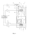
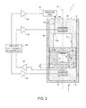
- the density measuring device 1 is shown in a non-operating condition (so-called "empty"), while in Figure 2 , the density measuring device 1 is shown in a measurement operating condition, immersed in a fluid 2 under test for which a density measurement is required, for example, pressed grapes inside a fermentation tank (not shown here).
- the density measuring device 1 comprises a measuring housing 4, having, for example, an elongated cylindrical shape, preferably of miniaturized size, for example with a diameter of less than 49 mm, to allow its insertion inside the fermentation tank, for example, through a ball valve with an effective entrance diameter of 49 mm (corresponding to a valve with the name DIN/MACON/GAROLLA 50/60, commonly used in the alcohol fermentation sector).
- the measuring housing 4 is therefore insertable in the fermentation tank and removable therefrom for routine and unplanned maintenance and for conservation at the end of the fermentation cycle, in a suitable location for preserving reliability (soaking in an inert, descaling and disinfectant solution).
- the density measuring device 1 has, inside the measuring housing 4, for example in its lower half (with respect to a normal measuring position), a measuring chamber 5 designed to be filled with the fluid 2 and internally housing a float 6.
- the measuring housing 4 has an axis of symmetry A, arranged, in the measuring position, parallel to a vertical axis z.
- the measuring chamber 5 is laterally defined by wall portions 5a and 5b, which also define a portion of the side wall of the measuring housing 4, shaped as a grating, or grill, so that the fluid 2 can pass through it when the measuring device 1 is at least partially immersed in the fluid 2, i.e. in a measurement operating condition.
- the same wall portions 5a and 5b also laterally contain the float 6 inside the measuring chamber 5 when the density measuring device 1 is not immersed in the fluid 2, i.e. in the non-operating condition (in which, as shown in Figure 1 , the float 6 rests on a base portion 4a of the measuring housing 4, with the density measuring device 1 in the vertical position).
- the measuring chamber 5 is also delimited at the bottom (with respect to the vertical axis z) by the same base portion 4a of the measuring housing 4.
- the float 6 internally includes two permanent magnets 10, 11, with opposing magnetic fields that, due to their physically opposite positions, reduce the force of the overall magnetic field of the float so as to make it less sensitive to the action of external magnetic fields, which could disturb the measurement.
- the float 6 is formed by a generically parallelepipedal, internally hollow body, and the permanent magnets 10 and 11 are connected to internally opposite walls of this hollow body, so that they are facing each other.
- the density measuring device 1 comprises a suspension solenoid 12, housed in the base portion 4a of the measuring housing 4, at the axis of symmetry A, so as to generate, when electrically powered, a magnetic field inside the measuring chamber 5, able to interact with the pair of permanent magnets 10 and 11 of the float 6.
- the suspension solenoid 12 when suitably controlled, enables keeping the float 6 suspended at a certain predetermined reference distance d from the base portion 4a of the measuring housing 4 (measured along the vertical direction z), by suitably varying the force of the generated magnetic field.
- the density measuring device 1 further comprises, again housed in the base portion 4a, close to the suspension solenoid 12 and at the axis of symmetry A, a position measuring device 14, in particular a Hall-effect measuring device (of a known type, not described in detail herein), which enables, in the measurement operating condition, the indirect reading of the distance of the float 6 suspended in the fluid 2 from the base portion 4a, by measuring the intensity of the magnetic field due to interaction with the float 6.
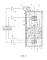
- a cleaning chamber 15 is obtained in an upper portion 4b of the measuring housing 4, arranged on the opposite side from the base portion 4a with respect to the measuring chamber 5 along the vertical axis z, such that it faces the measuring chamber 5.
- the upper portion 4b of the measuring housing has an inverted U shape in section and the cleaning chamber 15 defines a cavity obtained in this upper portion 4b, delimited laterally and at the top by the measuring housing 4 and in direct fluidic communication with the measuring chamber 5.
- a tubular conduit 16 passes through the upper portion 4b of the measuring housing 4, and has a first end 16a in communication with the cleaning chamber 15 and a second end 16b connected to a gas injection device 18 (shown schematically and, for example, including a porous candle for supplying oxygen).
- a gas injection device 18 shown schematically and, for example, including a porous candle for supplying oxygen.
- the gas injection device 18 is controlled so as to fill the inside of the cleaning chamber 15 with a gas, for example oxygen (O 2 ) in the gas phase, coming from an external depot to the wine-making tank (not shown), particularly when fermentation is not in progress; instead, when fermentation is in progress, the cleaning chamber 15 is independently fed with CO 2 coming from the fermentation process (the CO 2 , produced in the form of small bubbles by the fermentation of the must, a phenomenon in wine-making also known as 'perlage', remains trapped in the cleaning chamber 15, as the axis of symmetry A is kept parallel to the vertical axis z, perpendicular to the ground).
- a gas for example oxygen (O 2 ) in the gas phase
- the density measuring device 1 further comprises, housed in the upper portion 4b of the measuring housing 4, close to and above the cleaning chamber 15 and at the axis of symmetry A, a return solenoid 20, such as to generate, when electrically powered, a magnetic field able to interact with the pair of permanent magnets 10 and 11 of the float 6.
- the return solenoid 20, when suitably controlled, enables attracting the float 6, and in particular ensuring that the float 6 emerges from the fluid 2 in the measuring chamber 5 and enters the cleaning chamber 15.
- the float 6 in the cleaning operating condition, is completely housed in the cleaning chamber 15, being arranged in contact with the upper surface of the cleaning chamber 15.
- the suspension solenoid 12, the float 6 and the return solenoid 20 are also vertically aligned along the axis of symmetry A in the measurement ( Figure 2 ) and cleaning ( Figure 3 ) operating conditions.
- the positioning of the permanent magnets 10 and 11 at the top and bottom ends of the float 6 reduces the effective distance from the return solenoid 20 and the suspension solenoid 12, respectively, to a minimum, allowing the overall miniaturization of the density measuring device 1 (as previously indicated).
- the density measuring device 1 further comprises an electronic control circuit 22, shown schematically, arranged externally to the measuring housing 4 and the wine-making tank (in the exemplary use in the wine-making field), and suitably electrically connected (by the interposition of respective drivers 24) to the suspension solenoid 12, the return solenoid 20, the position sensor 14 and the gas injection device 18.
- the electronic control circuit 22 comprises a processing unit (for example a microprocessor or a microcontroller), a display for displaying the data readings regarding the density value of the fluid 2 and a user interface.
- the measuring housing 4 is inserted into the measurement environment suitable for storing the fluid, 2 the density of which it is desired to measure, for example inside a wine-making tank.
- the housing 4 is inserted keeping the axis of symmetry A perpendicular to the ground (parallel to the vertical axis z), so as to preserve a given amount of gas (air) inside the cleaning chamber 15, this gas being required for immediate operation of the density measuring device 1, even when there is no fermentation and with the gas injection device 18 not in operation, and so as to enable when fermentation is in process, as already mentioned, self-feeding of the cleaning chamber 15 with CO 2 fermentation gas (in wine-making, a phenomenon known as 'perlage').
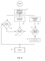
- the electronic control circuit 22 operates, electrically powering the suspension solenoid 12, which tends to attract the float 6, and reads, via the position sensor 14, the distance of the float 6 from the base portion 4a of the housing 4, step 31.
- the float 6 ( Figure 1 ) is free to move inside the housing 4, contained by the wall portions 5a and 5b, with no upward thrust force being exerted (due to the principle of Archimedes), given that no fluid is yet present inside the measuring chamber 5. Reading the density value in this phase is not meaningful and measuring the density is not possible, step 32, and so a corresponding indication for the user (for example, the message "OFF") is displayed on the display of the electronic control circuit 22. In particular, this indication informs that the measuring chamber is not flooded, step 33.
- Measurement operations on the density of the fluid 2 are then carried out, as measuring the density is possible in this situation (steps 31 and 32).
- the float 6 In the measurement condition, the float 6, due to the buoyancy effect, tends to rise upwards (i.e. it moves away from the base portion 4a), as it is designed to be lighter than the fluid 2, but it is held at a predetermined distance d by the suspension solenoid 12 powered by the electronic control circuit 22.
- the electronic control circuit 22 implements a feedback control loop, based on the values detected by position sensor 14, to adjust the electric current running through the suspension solenoid 12 to the value required for keeping the distance of the float 6 from the base portion 4a constant.
- the value of the current that runs through the suspension solenoid 12 is proportional to the value of the density of the fluid 2 present in the measuring chamber 5.
- This density value is conveniently shown on the display of the electronic control circuit 22 located outside the fermentation tank and stored and/or sent to other processing systems for further processing operations.
- the electronic control circuit 22 provides a procedure to cancel this magnetic interaction.
- the suspension solenoid 12 is deactivated for a very short time (to avoid the float 6 perceptibly changing position during this micro-interruption of the force holding it).
- the driver 24 that controls the suspension solenoid 12 there is a brief pause to wait for the magnetic flux to completely dissipate.
- the magnetic flux of the suspension solenoid 12 completely disappears, it is possible to read the position of the float accurately via the position sensor 14.
- the float 6 becomes covered with a plurality of fermentation gas bubbles that alter the volume and consequently the apparent specific weight, changing the density reading provided by the density measuring device 1 and rendering it unreliable.
- one aspect of the present invention envisages the execution, at predetermined time intervals, of a cleaning cycle of the float 6, for removing the bubbles that have adhered to it by capillarity and surface adhesion.
- the electronic control circuit 22 checks whether a predetermined time interval has elapsed since the last cleaning cycle, step 36, and, if so, starts a new cleaning cycle, step 38.
- the float 6 is attracted upwards and enters the cleaning chamber 15 full of gas (position shown in Figure 3 ), moving until it contacts the upper wall of the cleaning chamber 15: the impact and consequent rapid outflow of the liquid induces its cleaning by shaking, which allows cleaning the float of the deposits that were deposited on its surface.
- the float being inside the cleaning chamber 15 full of gas, it is also freed of the fermentation gas bubbles that formed on its surface due to surface adhesion when it was immersed in the fermenting fluid 2 in the measuring phase.
- the process of the fermentation of the mixture inside the wine-making tank a notoriously encrusting environment, entails solid organic and polluting particles being deposited on the float 6, these also destined to alter the correct reading of the density and also cause the clogging/jamming of moving parts of the density measuring device 1.
- the cleaning cycle advantageously provides for removing these clogging/jamming particles as well (by means of the above-mentioned mechanism of cleaning by shaking), restoring correct operation of the density measuring device 1.
- step 42 the electronic control circuit 22 checks whether a predetermined period scheduled for the cleaning cycle has elapsed; if this is not the case, the electronic control circuit 22 deactivates the return solenoid 20, step 44, and, in sequence, reactivates the suspension solenoid 12, step 45, in this way attracting the float 6 downwards again, into the measuring chamber 5.
- step 40 the electronic control circuit 22 inverting the activation and deactivation commands for the suspension and return solenoids 12 and 20 again, so as to attract the float 6 upwards.
- the float 6 is released, permanently this time, so as to be immersed in the fermenting liquid and attracted by the suspension solenoid 12, in this way starting again a correct measurement of the density for a new measurement cycle.
- the measurement cycle and the cleaning cycle thus mutually alternate, allowing high measurement accuracy for the density of the fermenting liquid to be achieved, for the entire duration of the fermentation process.
- the message "DIRTY" would be displayed on the display associated with the electronic control circuit 22, indicating that, as in this situation the measuring chamber 5 is flooded, as checked for again in step 33, the system anomaly is due to a possible inefficiency of the cleaning system and therefore, in a first hypothesis, to a probable lack of gas inside the cleaning chamber 15.
- Possible drops in the filling level of the cleaning chamber 15 may be due, for example, to bad positioning of the housing 4 in the insertion step, to the fermentation halting, or accidental gas leakage from the cleaning chamber 15.
- the electronic control circuit 22 then controls the injection of a quantity of gas into the cleaning chamber 15, to resolve the anomaly, before executing a subsequent cleaning cycle, step 37.
- the electronic control circuit 22 In the case where the electronic control circuit 22 records a certain number (set in the design phase) of "DIRTY" events within a certain predetermined period of time, it finally halts, showing a "FAILURE” message on the display and needs to be serviced by a specialized technical support engineer.
- the density measurement provided by the density measuring device 1 is therefore extremely reliable, even over long periods of measurement, as required, for example, for continuous, real-time fermentation mixture monitoring.
- the miniaturization of the density measuring device 1 allows mounting it on a rod for removable insertion in the measurement environment, that is, for example, a wine-making tank.
- This possibility of removal allows resolving a specific technical problem in making red wines, which provides for, when fermentation is completed, the so-called racking off, or rather the drawing off of the liquid part from the tank.
- the so-called marc cap which floats on the surface in the wine-making tank, descends, and as it is thick and compact, can hit and damage any part projecting from the inner wall of the tank (just like the density sensor if it has not been opportunely removed from the tank beforehand).
- the possibility of removing the density measuring device 1 therefore avoids having to provide a protective structure (such as a cover, for example) for installation inside the wine-making tank.
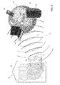
- the application of the density measuring device 1 is therefore exceedingly advantageous in an automated control system for the wine-making process, as schematically shown in Figure 6 (and as described in detail in the above-mentioned patent application WO 2011/058585 ).
- the automated control system indicated by reference numeral 50, comprises:
- the previously-described density measuring device 1 can be advantageously applied to all those cases where a density measurement is required in a hostile environment, in which, for example, there is an encrusting fluid, with solid particles in suspension and/or gas supersaturation.
- the position sensor 14 could be an LVDT sensor, or operate according to electrostatic principles instead of the Hall effect; the arrangement of the cleaning chamber 15 and the suspension and return solenoids 12, 20 could be inverted with respect to the measuring chamber 5 along the vertical axis z (in particular, in the case where the float 6 was heavier than the fluid 2, instead of being lighter than the fluid 2, as in the previously illustrated case); the force exerted on the float 6 due to the principle of Archimedes could be measured by means of a balance, opportunely connected to the float 6, instead of being obtained indirectly from the value of the electric current supplied to the return solenoid 20 by means of the position control loop; or the float 6 could be kept in suspension and moved in a different manner with respect to electromagnetic actuation.
Landscapes
- Chemical & Material Sciences (AREA)
- Health & Medical Sciences (AREA)
- Life Sciences & Earth Sciences (AREA)
- Biochemistry (AREA)
- General Health & Medical Sciences (AREA)
- Organic Chemistry (AREA)
- Analytical Chemistry (AREA)
- General Physics & Mathematics (AREA)
- Immunology (AREA)
- Pathology (AREA)
- Physics & Mathematics (AREA)
- Engineering & Computer Science (AREA)
- General Engineering & Computer Science (AREA)
- Genetics & Genomics (AREA)
- Bioinformatics & Cheminformatics (AREA)
- Wood Science & Technology (AREA)
- Zoology (AREA)
- Apparatus Associated With Microorganisms And Enzymes (AREA)
- Level Indicators Using A Float (AREA)
- Hard Magnetic Materials (AREA)
Applications Claiming Priority (1)
| Application Number | Priority Date | Filing Date | Title |
|---|---|---|---|
| IT000728A ITTO20120728A1 (it) | 2012-08-14 | 2012-08-14 | Dispositivo di misura di densita' a sospensione magnetica adatto all'utilizzo in ambienti ostili, e relativo metodo di funzionamento |
Publications (5)
| Publication Number | Publication Date |
|---|---|
| EP2698620A2 true EP2698620A2 (fr) | 2014-02-19 |
| EP2698620A3 EP2698620A3 (fr) | 2014-04-09 |
| EP2698620A9 EP2698620A9 (fr) | 2014-05-28 |
| EP2698620A8 EP2698620A8 (fr) | 2014-06-11 |
| EP2698620B1 EP2698620B1 (fr) | 2017-11-15 |
Family
ID=47046764
Family Applications (1)
| Application Number | Title | Priority Date | Filing Date |
|---|---|---|---|
| EP13180246.4A Not-in-force EP2698620B1 (fr) | 2012-08-14 | 2013-08-13 | appareil de mesure de la densité d'une suspension magnetique dans un environnement hostile et methode d'operation |
Country Status (5)
| Country | Link |
|---|---|
| US (1) | US9328321B2 (fr) |
| EP (1) | EP2698620B1 (fr) |
| ES (1) | ES2657831T3 (fr) |
| IT (1) | ITTO20120728A1 (fr) |
| PT (1) | PT2698620T (fr) |
Cited By (8)
| Publication number | Priority date | Publication date | Assignee | Title |
|---|---|---|---|---|
| CN104503238A (zh) * | 2014-12-15 | 2015-04-08 | 北京航空航天大学 | 一种基于自适应重复控制器的磁悬浮转子系统电流谐波抑制方法 |
| CN105159342A (zh) * | 2015-09-06 | 2015-12-16 | 北京航空航天大学 | 一种基于并联相移滤波器的磁悬浮转子谐波电流抑制方法 |
| CN108593497A (zh) * | 2018-05-30 | 2018-09-28 | 中国工程物理研究院激光聚变研究中心 | 一种精确测量自支撑铍薄膜密度的方法 |
| CN109270572A (zh) * | 2018-11-19 | 2019-01-25 | 西安石油大学 | 磁悬浮霍尔效应地震检波器及微测井地震数据采集系统 |
| WO2019149838A1 (fr) | 2018-02-05 | 2019-08-08 | Universite de Bordeaux | Dispositif et procede de mesure de la masse volumique d'un liquide sursature en gaz |
| CN111781907A (zh) * | 2020-07-31 | 2020-10-16 | 中国美术学院 | 一种葡萄酒机检测控制电路 |
| FR3121016A1 (fr) * | 2021-03-23 | 2022-09-30 | Bucher Vaslin | Pressoir, notamment pour une application dans le domaine viticole |
| IT202200023430A1 (it) * | 2022-11-14 | 2024-05-14 | Gimar S R L | Procedimento ed apparato per la vinificazione di un pigiato d’uva |
Families Citing this family (8)
| Publication number | Priority date | Publication date | Assignee | Title |
|---|---|---|---|---|
| ES3071977T3 (en) * | 2015-11-30 | 2026-06-26 | Bourns Inc | Detecting fluid level via a float |
| US10379023B2 (en) | 2016-11-15 | 2019-08-13 | Fresenius Medical Care Holdings, Inc. | Digital hydrometer assistant reader |
| US10300869B1 (en) * | 2017-11-30 | 2019-05-28 | Ford Global Technologies, Llc | Washer fluid tank with magnetically responsive sensors |
| CN109395671B (zh) * | 2018-11-28 | 2023-08-25 | 南京浦世环境科技发展有限公司 | 一种气液固三相反应的旁路监测装置及其在二氧化碳矿物封存中的应用 |
| CN111470189B (zh) * | 2019-01-24 | 2022-02-01 | 中国石油天然气股份有限公司 | 用于储罐的辅助装置、检测装置及使用方法 |
| US11761870B2 (en) | 2021-06-01 | 2023-09-19 | The Government of the United States of America, as represented by the Secretary of Homeland Security | Miniature wireless concentration meter |
| FR3127044B1 (fr) * | 2021-09-10 | 2025-09-19 | My Bacchus | dispositif pour la surveillance de liquide, en particulier de liquide fermentescible, tel que du moût, en particulier lors de la fermentation dudit liquide |
| US12014619B2 (en) * | 2022-09-13 | 2024-06-18 | Veronica Berry-Jones | Pressure-sensing steering wheel cover device |
Citations (2)
| Publication number | Priority date | Publication date | Assignee | Title |
|---|---|---|---|---|
| FR2563339A1 (fr) | 1984-04-20 | 1985-10-25 | Prulho Robert Sa | Densimetre electromagnetique a flotteur partiellement immerge |
| WO2011058585A1 (fr) | 2009-11-10 | 2011-05-19 | Carlo Farotto | Système automatisé de vinification et procédé de vinification associé |
Family Cites Families (7)
| Publication number | Priority date | Publication date | Assignee | Title |
|---|---|---|---|---|
| US1491487A (en) * | 1922-11-08 | 1924-04-22 | Dwight R Means | Recording hydrometer |
| US2958224A (en) * | 1954-11-29 | 1960-11-01 | Edelmann Leo | Thermohydrometer |
| US3631727A (en) * | 1969-12-10 | 1972-01-04 | Mulwhlteson Dev Co | Device for measuring specific gravity of fluids |
| JPS56136381A (en) * | 1980-03-28 | 1981-10-24 | Sharp Corp | Control of viscosity of jet ink |
| US4720998A (en) * | 1986-06-13 | 1988-01-26 | Hogue James D | Crude oil sampling system |
| US5900547A (en) * | 1997-09-12 | 1999-05-04 | Thermoprobe Inc. | Differential level hydrometer |
| FR2825450B1 (fr) * | 2001-05-31 | 2004-01-16 | Centre Nat Rech Scient | Installation de refroidissement par vaporisation partielle a basse pression d'un jus chauffe |
-
2012
- 2012-08-14 IT IT000728A patent/ITTO20120728A1/it unknown
-
2013
- 2013-08-13 PT PT131802464T patent/PT2698620T/pt unknown
- 2013-08-13 EP EP13180246.4A patent/EP2698620B1/fr not_active Not-in-force
- 2013-08-13 US US13/965,882 patent/US9328321B2/en not_active Expired - Fee Related
- 2013-08-13 ES ES13180246.4T patent/ES2657831T3/es active Active
Patent Citations (2)
| Publication number | Priority date | Publication date | Assignee | Title |
|---|---|---|---|---|
| FR2563339A1 (fr) | 1984-04-20 | 1985-10-25 | Prulho Robert Sa | Densimetre electromagnetique a flotteur partiellement immerge |
| WO2011058585A1 (fr) | 2009-11-10 | 2011-05-19 | Carlo Farotto | Système automatisé de vinification et procédé de vinification associé |
Non-Patent Citations (2)
| Title |
|---|
| S. K. SINGH: "Industrial Instrumentation and Control", 2008, MCGRAW HILL, pages: 253 |
| SABLAYROLLES, J. M: "Control of alcoholic fermentation in winemaking: Current Situation and prospect", 2009, FOOD RESEARCH INTERNATIONAL |
Cited By (12)
| Publication number | Priority date | Publication date | Assignee | Title |
|---|---|---|---|---|
| CN104503238A (zh) * | 2014-12-15 | 2015-04-08 | 北京航空航天大学 | 一种基于自适应重复控制器的磁悬浮转子系统电流谐波抑制方法 |
| CN104503238B (zh) * | 2014-12-15 | 2017-03-22 | 北京航空航天大学 | 一种基于自适应重复控制器的磁悬浮转子系统电流谐波抑制方法 |
| CN105159342A (zh) * | 2015-09-06 | 2015-12-16 | 北京航空航天大学 | 一种基于并联相移滤波器的磁悬浮转子谐波电流抑制方法 |
| CN105159342B (zh) * | 2015-09-06 | 2017-06-20 | 北京航空航天大学 | 一种基于并联相移滤波器的磁悬浮转子谐波电流抑制方法 |
| WO2019149838A1 (fr) | 2018-02-05 | 2019-08-08 | Universite de Bordeaux | Dispositif et procede de mesure de la masse volumique d'un liquide sursature en gaz |
| FR3077643A1 (fr) * | 2018-02-05 | 2019-08-09 | Universite de Bordeaux | Dispositif et procede de mesure de la masse volumique d'un liquide sursature en gaz |
| CN108593497A (zh) * | 2018-05-30 | 2018-09-28 | 中国工程物理研究院激光聚变研究中心 | 一种精确测量自支撑铍薄膜密度的方法 |
| CN109270572A (zh) * | 2018-11-19 | 2019-01-25 | 西安石油大学 | 磁悬浮霍尔效应地震检波器及微测井地震数据采集系统 |
| CN111781907A (zh) * | 2020-07-31 | 2020-10-16 | 中国美术学院 | 一种葡萄酒机检测控制电路 |
| FR3121016A1 (fr) * | 2021-03-23 | 2022-09-30 | Bucher Vaslin | Pressoir, notamment pour une application dans le domaine viticole |
| IT202200023430A1 (it) * | 2022-11-14 | 2024-05-14 | Gimar S R L | Procedimento ed apparato per la vinificazione di un pigiato d’uva |
| EP4417679A1 (fr) * | 2022-11-14 | 2024-08-21 | Gimar S.r.l. | Procédé et dispositif pour la vinification de raisins broyés |
Also Published As
| Publication number | Publication date |
|---|---|
| ITTO20120728A1 (it) | 2014-02-15 |
| PT2698620T (pt) | 2018-02-13 |
| EP2698620B1 (fr) | 2017-11-15 |
| EP2698620A8 (fr) | 2014-06-11 |
| EP2698620A9 (fr) | 2014-05-28 |
| US20140157992A1 (en) | 2014-06-12 |
| US9328321B2 (en) | 2016-05-03 |
| EP2698620A3 (fr) | 2014-04-09 |
| ES2657831T3 (es) | 2018-03-07 |
Similar Documents
| Publication | Publication Date | Title |
|---|---|---|
| EP2698620B1 (fr) | appareil de mesure de la densité d'une suspension magnetique dans un environnement hostile et methode d'operation | |
| CN102148285B (zh) | 定容式精准自动补液装置 | |
| US9074587B2 (en) | Energy efficient sewage pumping system with a controller and variable frequency drive and method | |
| US20020076330A1 (en) | Pneumatic pump control system method and apparatus | |
| CN107152019B (zh) | 液压振冲器智能控制系统及其控制方法 | |
| WO2012066548A1 (fr) | Système de capteur | |
| CN115015344B (zh) | 一种全自动在线测量反应釜内悬浮反应液pH的系统与方法 | |
| US20190002815A1 (en) | Large-scale Bioreactor | |
| TWI224982B (en) | Automatic pipette device with rinsing | |
| KR101773113B1 (ko) | 자동 채수 장치 | |
| CN207516837U (zh) | 一种液位监测控制装置 | |
| CN201561730U (zh) | 计量标尺 | |
| CN209038288U (zh) | 一种可自动补料的储液罐 | |
| EP4368983B1 (fr) | Appareil de mesure | |
| CN111132595A (zh) | 大型生物反应器 | |
| CN113670777A (zh) | 一种渗吸实验方法 | |
| HK1224378A1 (zh) | 在确定工艺材料浓度时自动切换参照模型 | |
| JP2001018053A (ja) | 鋳造機の給湯装置 | |
| CN111408512A (zh) | 一种蒸压加气混凝土板拔钎浸蜡装置及其控制方法 | |
| CN208537989U (zh) | 一种污水液位控制装置 | |
| CN213986072U (zh) | 一种测量试块悬浸质量自动检测设备 | |
| CN112304013A (zh) | 储水装置、制冷设备及冰箱 | |
| CN220835206U (zh) | 一种耐腐蚀石墨消解仪 | |
| CN217816180U (zh) | 一种液氮添加装置 | |
| CN201517932U (zh) | 原油计量装置 |
Legal Events
| Date | Code | Title | Description |
|---|---|---|---|
| AK | Designated contracting states |
Kind code of ref document: A2 Designated state(s): AL AT BE BG CH CY CZ DE DK EE ES FI FR GB GR HR HU IE IS IT LI LT LU LV MC MK MT NL NO PL PT RO RS SE SI SK SM TR |
|
| AX | Request for extension of the european patent |
Extension state: BA ME |
|
| PUAI | Public reference made under article 153(3) epc to a published international application that has entered the european phase |
Free format text: ORIGINAL CODE: 0009012 |
|
| PUAL | Search report despatched |
Free format text: ORIGINAL CODE: 0009013 |
|
| AK | Designated contracting states |
Kind code of ref document: A3 Designated state(s): AL AT BE BG CH CY CZ DE DK EE ES FI FR GB GR HR HU IE IS IT LI LT LU LV MC MK MT NL NO PL PT RO RS SE SI SK SM TR |
|
| AX | Request for extension of the european patent |
Extension state: BA ME |
|
| RIC1 | Information provided on ipc code assigned before grant |
Ipc: G01N 9/12 20060101AFI20140304BHEP Ipc: G01N 9/14 20060101ALI20140304BHEP |
|
| 17P | Request for examination filed |
Effective date: 20141009 |
|
| RBV | Designated contracting states (corrected) |
Designated state(s): AL AT BE BG CH CY CZ DE DK EE ES FI FR GB GR HR HU IE IS IT LI LT LU LV MC MK MT NL NO PL PT RO RS SE SI SK SM TR |
|
| GRAP | Despatch of communication of intention to grant a patent |
Free format text: ORIGINAL CODE: EPIDOSNIGR1 |
|
| INTG | Intention to grant announced |
Effective date: 20170220 |
|
| GRAS | Grant fee paid |
Free format text: ORIGINAL CODE: EPIDOSNIGR3 |
|
| GRAJ | Information related to disapproval of communication of intention to grant by the applicant or resumption of examination proceedings by the epo deleted |
Free format text: ORIGINAL CODE: EPIDOSDIGR1 |
|
| GRAL | Information related to payment of fee for publishing/printing deleted |
Free format text: ORIGINAL CODE: EPIDOSDIGR3 |
|
| INTC | Intention to grant announced (deleted) | ||
| GRAR | Information related to intention to grant a patent recorded |
Free format text: ORIGINAL CODE: EPIDOSNIGR71 |
|
| GRAA | (expected) grant |
Free format text: ORIGINAL CODE: 0009210 |
|
| INTG | Intention to grant announced |
Effective date: 20171003 |
|
| RAP1 | Party data changed (applicant data changed or rights of an application transferred) |
Owner name: FAROTTO, CARLO |
|
| RIN1 | Information on inventor provided before grant (corrected) |
Inventor name: FAROTTO, CARLO |
|
| AK | Designated contracting states |
Kind code of ref document: B1 Designated state(s): AL AT BE BG CH CY CZ DE DK EE ES FI FR GB GR HR HU IE IS IT LI LT LU LV MC MK MT NL NO PL PT RO RS SE SI SK SM TR |
|
| REG | Reference to a national code |
Ref country code: CH Ref legal event code: EP Ref country code: GB Ref legal event code: FG4D Ref country code: AT Ref legal event code: REF Ref document number: 946757 Country of ref document: AT Kind code of ref document: T Effective date: 20171115 |
|
| REG | Reference to a national code |
Ref country code: IE Ref legal event code: FG4D |
|
| REG | Reference to a national code |
Ref country code: DE Ref legal event code: R096 Ref document number: 602013029387 Country of ref document: DE |
|
| REG | Reference to a national code |
Ref country code: CH Ref legal event code: NV Representative=s name: BOHEST AG, CH |
|
| REG | Reference to a national code |
Ref country code: PT Ref legal event code: SC4A Ref document number: 2698620 Country of ref document: PT Date of ref document: 20180213 Kind code of ref document: T Free format text: AVAILABILITY OF NATIONAL TRANSLATION Effective date: 20180207 |
|
| REG | Reference to a national code |
Ref country code: ES Ref legal event code: FG2A Ref document number: 2657831 Country of ref document: ES Kind code of ref document: T3 Effective date: 20180307 |
|
| REG | Reference to a national code |
Ref country code: NL Ref legal event code: MP Effective date: 20171115 |
|
| REG | Reference to a national code |
Ref country code: LT Ref legal event code: MG4D |
|
| REG | Reference to a national code |
Ref country code: AT Ref legal event code: MK05 Ref document number: 946757 Country of ref document: AT Kind code of ref document: T Effective date: 20171115 |
|
| PG25 | Lapsed in a contracting state [announced via postgrant information from national office to epo] |
Ref country code: NO Free format text: LAPSE BECAUSE OF FAILURE TO SUBMIT A TRANSLATION OF THE DESCRIPTION OR TO PAY THE FEE WITHIN THE PRESCRIBED TIME-LIMIT Effective date: 20180215 Ref country code: NL Free format text: LAPSE BECAUSE OF FAILURE TO SUBMIT A TRANSLATION OF THE DESCRIPTION OR TO PAY THE FEE WITHIN THE PRESCRIBED TIME-LIMIT Effective date: 20171115 Ref country code: SE Free format text: LAPSE BECAUSE OF FAILURE TO SUBMIT A TRANSLATION OF THE DESCRIPTION OR TO PAY THE FEE WITHIN THE PRESCRIBED TIME-LIMIT Effective date: 20171115 Ref country code: LT Free format text: LAPSE BECAUSE OF FAILURE TO SUBMIT A TRANSLATION OF THE DESCRIPTION OR TO PAY THE FEE WITHIN THE PRESCRIBED TIME-LIMIT Effective date: 20171115 Ref country code: FI Free format text: LAPSE BECAUSE OF FAILURE TO SUBMIT A TRANSLATION OF THE DESCRIPTION OR TO PAY THE FEE WITHIN THE PRESCRIBED TIME-LIMIT Effective date: 20171115 |
|
| PG25 | Lapsed in a contracting state [announced via postgrant information from national office to epo] |
Ref country code: AT Free format text: LAPSE BECAUSE OF FAILURE TO SUBMIT A TRANSLATION OF THE DESCRIPTION OR TO PAY THE FEE WITHIN THE PRESCRIBED TIME-LIMIT Effective date: 20171115 Ref country code: LV Free format text: LAPSE BECAUSE OF FAILURE TO SUBMIT A TRANSLATION OF THE DESCRIPTION OR TO PAY THE FEE WITHIN THE PRESCRIBED TIME-LIMIT Effective date: 20171115 Ref country code: HR Free format text: LAPSE BECAUSE OF FAILURE TO SUBMIT A TRANSLATION OF THE DESCRIPTION OR TO PAY THE FEE WITHIN THE PRESCRIBED TIME-LIMIT Effective date: 20171115 Ref country code: RS Free format text: LAPSE BECAUSE OF FAILURE TO SUBMIT A TRANSLATION OF THE DESCRIPTION OR TO PAY THE FEE WITHIN THE PRESCRIBED TIME-LIMIT Effective date: 20171115 Ref country code: BG Free format text: LAPSE BECAUSE OF FAILURE TO SUBMIT A TRANSLATION OF THE DESCRIPTION OR TO PAY THE FEE WITHIN THE PRESCRIBED TIME-LIMIT Effective date: 20180215 Ref country code: GR Free format text: LAPSE BECAUSE OF FAILURE TO SUBMIT A TRANSLATION OF THE DESCRIPTION OR TO PAY THE FEE WITHIN THE PRESCRIBED TIME-LIMIT Effective date: 20180216 |
|
| PG25 | Lapsed in a contracting state [announced via postgrant information from national office to epo] |
Ref country code: CZ Free format text: LAPSE BECAUSE OF FAILURE TO SUBMIT A TRANSLATION OF THE DESCRIPTION OR TO PAY THE FEE WITHIN THE PRESCRIBED TIME-LIMIT Effective date: 20171115 Ref country code: SK Free format text: LAPSE BECAUSE OF FAILURE TO SUBMIT A TRANSLATION OF THE DESCRIPTION OR TO PAY THE FEE WITHIN THE PRESCRIBED TIME-LIMIT Effective date: 20171115 Ref country code: DK Free format text: LAPSE BECAUSE OF FAILURE TO SUBMIT A TRANSLATION OF THE DESCRIPTION OR TO PAY THE FEE WITHIN THE PRESCRIBED TIME-LIMIT Effective date: 20171115 Ref country code: EE Free format text: LAPSE BECAUSE OF FAILURE TO SUBMIT A TRANSLATION OF THE DESCRIPTION OR TO PAY THE FEE WITHIN THE PRESCRIBED TIME-LIMIT Effective date: 20171115 Ref country code: CY Free format text: LAPSE BECAUSE OF FAILURE TO SUBMIT A TRANSLATION OF THE DESCRIPTION OR TO PAY THE FEE WITHIN THE PRESCRIBED TIME-LIMIT Effective date: 20171115 |
|
| REG | Reference to a national code |
Ref country code: DE Ref legal event code: R097 Ref document number: 602013029387 Country of ref document: DE |
|
| REG | Reference to a national code |
Ref country code: FR Ref legal event code: PLFP Year of fee payment: 6 |
|
| PG25 | Lapsed in a contracting state [announced via postgrant information from national office to epo] |
Ref country code: IT Free format text: LAPSE BECAUSE OF FAILURE TO SUBMIT A TRANSLATION OF THE DESCRIPTION OR TO PAY THE FEE WITHIN THE PRESCRIBED TIME-LIMIT Effective date: 20171115 Ref country code: RO Free format text: LAPSE BECAUSE OF FAILURE TO SUBMIT A TRANSLATION OF THE DESCRIPTION OR TO PAY THE FEE WITHIN THE PRESCRIBED TIME-LIMIT Effective date: 20171115 Ref country code: PL Free format text: LAPSE BECAUSE OF FAILURE TO SUBMIT A TRANSLATION OF THE DESCRIPTION OR TO PAY THE FEE WITHIN THE PRESCRIBED TIME-LIMIT Effective date: 20171115 Ref country code: SM Free format text: LAPSE BECAUSE OF FAILURE TO SUBMIT A TRANSLATION OF THE DESCRIPTION OR TO PAY THE FEE WITHIN THE PRESCRIBED TIME-LIMIT Effective date: 20171115 |
|
| PLBE | No opposition filed within time limit |
Free format text: ORIGINAL CODE: 0009261 |
|
| STAA | Information on the status of an ep patent application or granted ep patent |
Free format text: STATUS: NO OPPOSITION FILED WITHIN TIME LIMIT |
|
| 26N | No opposition filed |
Effective date: 20180817 |
|
| PG25 | Lapsed in a contracting state [announced via postgrant information from national office to epo] |
Ref country code: SI Free format text: LAPSE BECAUSE OF FAILURE TO SUBMIT A TRANSLATION OF THE DESCRIPTION OR TO PAY THE FEE WITHIN THE PRESCRIBED TIME-LIMIT Effective date: 20171115 |
|
| PGFP | Annual fee paid to national office [announced via postgrant information from national office to epo] |
Ref country code: CH Payment date: 20180824 Year of fee payment: 6 |
|
| PGFP | Annual fee paid to national office [announced via postgrant information from national office to epo] |
Ref country code: PT Payment date: 20180806 Year of fee payment: 6 |
|
| PGFP | Annual fee paid to national office [announced via postgrant information from national office to epo] |
Ref country code: DE Payment date: 20181031 Year of fee payment: 6 |
|
| PG25 | Lapsed in a contracting state [announced via postgrant information from national office to epo] |
Ref country code: MC Free format text: LAPSE BECAUSE OF FAILURE TO SUBMIT A TRANSLATION OF THE DESCRIPTION OR TO PAY THE FEE WITHIN THE PRESCRIBED TIME-LIMIT Effective date: 20171115 |
|
| GBPC | Gb: european patent ceased through non-payment of renewal fee |
Effective date: 20180813 |
|
| PG25 | Lapsed in a contracting state [announced via postgrant information from national office to epo] |
Ref country code: LU Free format text: LAPSE BECAUSE OF NON-PAYMENT OF DUE FEES Effective date: 20180813 |
|
| REG | Reference to a national code |
Ref country code: BE Ref legal event code: MM Effective date: 20180831 |
|
| REG | Reference to a national code |
Ref country code: IE Ref legal event code: MM4A |
|
| PG25 | Lapsed in a contracting state [announced via postgrant information from national office to epo] |
Ref country code: IE Free format text: LAPSE BECAUSE OF NON-PAYMENT OF DUE FEES Effective date: 20180813 |
|
| PG25 | Lapsed in a contracting state [announced via postgrant information from national office to epo] |
Ref country code: BE Free format text: LAPSE BECAUSE OF NON-PAYMENT OF DUE FEES Effective date: 20180831 |
|
| PG25 | Lapsed in a contracting state [announced via postgrant information from national office to epo] |
Ref country code: GB Free format text: LAPSE BECAUSE OF NON-PAYMENT OF DUE FEES Effective date: 20180813 |
|
| PG25 | Lapsed in a contracting state [announced via postgrant information from national office to epo] |
Ref country code: MT Free format text: LAPSE BECAUSE OF NON-PAYMENT OF DUE FEES Effective date: 20180813 |
|
| PGFP | Annual fee paid to national office [announced via postgrant information from national office to epo] |
Ref country code: ES Payment date: 20191003 Year of fee payment: 7 |
|
| REG | Reference to a national code |
Ref country code: DE Ref legal event code: R119 Ref document number: 602013029387 Country of ref document: DE |
|
| PG25 | Lapsed in a contracting state [announced via postgrant information from national office to epo] |
Ref country code: TR Free format text: LAPSE BECAUSE OF FAILURE TO SUBMIT A TRANSLATION OF THE DESCRIPTION OR TO PAY THE FEE WITHIN THE PRESCRIBED TIME-LIMIT Effective date: 20171115 |
|
| PG25 | Lapsed in a contracting state [announced via postgrant information from national office to epo] |
Ref country code: PT Free format text: LAPSE BECAUSE OF NON-PAYMENT OF DUE FEES Effective date: 20200213 |
|
| PG25 | Lapsed in a contracting state [announced via postgrant information from national office to epo] |
Ref country code: CH Free format text: LAPSE BECAUSE OF NON-PAYMENT OF DUE FEES Effective date: 20190831 Ref country code: HU Free format text: LAPSE BECAUSE OF FAILURE TO SUBMIT A TRANSLATION OF THE DESCRIPTION OR TO PAY THE FEE WITHIN THE PRESCRIBED TIME-LIMIT; INVALID AB INITIO Effective date: 20130813 Ref country code: LI Free format text: LAPSE BECAUSE OF NON-PAYMENT OF DUE FEES Effective date: 20190831 |
|
| PG25 | Lapsed in a contracting state [announced via postgrant information from national office to epo] |
Ref country code: MK Free format text: LAPSE BECAUSE OF NON-PAYMENT OF DUE FEES Effective date: 20171115 |
|
| PG25 | Lapsed in a contracting state [announced via postgrant information from national office to epo] |
Ref country code: AL Free format text: LAPSE BECAUSE OF FAILURE TO SUBMIT A TRANSLATION OF THE DESCRIPTION OR TO PAY THE FEE WITHIN THE PRESCRIBED TIME-LIMIT Effective date: 20171115 Ref country code: DE Free format text: LAPSE BECAUSE OF NON-PAYMENT OF DUE FEES Effective date: 20200303 Ref country code: IS Free format text: LAPSE BECAUSE OF FAILURE TO SUBMIT A TRANSLATION OF THE DESCRIPTION OR TO PAY THE FEE WITHIN THE PRESCRIBED TIME-LIMIT Effective date: 20180315 |
|
| PGFP | Annual fee paid to national office [announced via postgrant information from national office to epo] |
Ref country code: FR Payment date: 20200824 Year of fee payment: 8 |
|
| REG | Reference to a national code |
Ref country code: ES Ref legal event code: FD2A Effective date: 20220110 |
|
| PG25 | Lapsed in a contracting state [announced via postgrant information from national office to epo] |
Ref country code: ES Free format text: LAPSE BECAUSE OF NON-PAYMENT OF DUE FEES Effective date: 20200814 |
|
| PG25 | Lapsed in a contracting state [announced via postgrant information from national office to epo] |
Ref country code: FR Free format text: LAPSE BECAUSE OF NON-PAYMENT OF DUE FEES Effective date: 20210831 |