EP2698935B1 - Kanalmessverfahren und -vorrichtung - Google Patents
Kanalmessverfahren und -vorrichtung Download PDFInfo
- Publication number
- EP2698935B1 EP2698935B1 EP12782417.5A EP12782417A EP2698935B1 EP 2698935 B1 EP2698935 B1 EP 2698935B1 EP 12782417 A EP12782417 A EP 12782417A EP 2698935 B1 EP2698935 B1 EP 2698935B1
- Authority
- EP
- European Patent Office
- Prior art keywords
- reference signal
- frequency bands
- information
- measurement
- signal information
- Prior art date
- Legal status (The legal status is an assumption and is not a legal conclusion. Google has not performed a legal analysis and makes no representation as to the accuracy of the status listed.)
- Active
Links
Images


Classifications
-
- H—ELECTRICITY
- H04—ELECTRIC COMMUNICATION TECHNIQUE
- H04L—TRANSMISSION OF DIGITAL INFORMATION, e.g. TELEGRAPHIC COMMUNICATION
- H04L5/00—Arrangements affording multiple use of the transmission path
- H04L5/003—Arrangements for allocating sub-channels of the transmission path
- H04L5/0048—Allocation of pilot signals, i.e. of signals known to the receiver
-
- H—ELECTRICITY
- H04—ELECTRIC COMMUNICATION TECHNIQUE
- H04W—WIRELESS COMMUNICATION NETWORKS
- H04W24/00—Supervisory, monitoring or testing arrangements
- H04W24/08—Testing, supervising or monitoring using real traffic
-
- H—ELECTRICITY
- H04—ELECTRIC COMMUNICATION TECHNIQUE
- H04L—TRANSMISSION OF DIGITAL INFORMATION, e.g. TELEGRAPHIC COMMUNICATION
- H04L5/00—Arrangements affording multiple use of the transmission path
- H04L5/0091—Signalling for the administration of the divided path, e.g. signalling of configuration information
- H04L5/0092—Indication of how the channel is divided
-
- H—ELECTRICITY
- H04—ELECTRIC COMMUNICATION TECHNIQUE
- H04B—TRANSMISSION
- H04B7/00—Radio transmission systems, i.e. using radiation field
- H04B7/02—Diversity systems; Multi-antenna system, i.e. transmission or reception using multiple antennas
- H04B7/04—Diversity systems; Multi-antenna system, i.e. transmission or reception using multiple antennas using two or more spaced independent antennas
- H04B7/06—Diversity systems; Multi-antenna system, i.e. transmission or reception using multiple antennas using two or more spaced independent antennas at the transmitting station
- H04B7/0613—Diversity systems; Multi-antenna system, i.e. transmission or reception using multiple antennas using two or more spaced independent antennas at the transmitting station using simultaneous transmission
- H04B7/0615—Diversity systems; Multi-antenna system, i.e. transmission or reception using multiple antennas using two or more spaced independent antennas at the transmitting station using simultaneous transmission of weighted versions of same signal
- H04B7/0619—Diversity systems; Multi-antenna system, i.e. transmission or reception using multiple antennas using two or more spaced independent antennas at the transmitting station using simultaneous transmission of weighted versions of same signal using feedback from receiving side
- H04B7/0621—Feedback content
- H04B7/063—Parameters other than those covered in groups H04B7/0623 - H04B7/0634, e.g. channel matrix rank or transmit mode selection
-
- H—ELECTRICITY
- H04—ELECTRIC COMMUNICATION TECHNIQUE
- H04B—TRANSMISSION
- H04B7/00—Radio transmission systems, i.e. using radiation field
- H04B7/02—Diversity systems; Multi-antenna system, i.e. transmission or reception using multiple antennas
- H04B7/04—Diversity systems; Multi-antenna system, i.e. transmission or reception using multiple antennas using two or more spaced independent antennas
- H04B7/06—Diversity systems; Multi-antenna system, i.e. transmission or reception using multiple antennas using two or more spaced independent antennas at the transmitting station
- H04B7/0613—Diversity systems; Multi-antenna system, i.e. transmission or reception using multiple antennas using two or more spaced independent antennas at the transmitting station using simultaneous transmission
- H04B7/0615—Diversity systems; Multi-antenna system, i.e. transmission or reception using multiple antennas using two or more spaced independent antennas at the transmitting station using simultaneous transmission of weighted versions of same signal
- H04B7/0619—Diversity systems; Multi-antenna system, i.e. transmission or reception using multiple antennas using two or more spaced independent antennas at the transmitting station using simultaneous transmission of weighted versions of same signal using feedback from receiving side
- H04B7/0636—Feedback format
- H04B7/0639—Using selective indices, e.g. of a codebook, e.g. pre-distortion matrix index [PMI] or for beam selection
-
- H—ELECTRICITY
- H04—ELECTRIC COMMUNICATION TECHNIQUE
- H04L—TRANSMISSION OF DIGITAL INFORMATION, e.g. TELEGRAPHIC COMMUNICATION
- H04L25/00—Baseband systems
- H04L25/02—Details ; arrangements for supplying electrical power along data transmission lines
- H04L25/0202—Channel estimation
- H04L25/0224—Channel estimation using sounding signals
- H04L25/0226—Channel estimation using sounding signals sounding signals per se
Definitions
- Embodiments of the present invention relate to the field of wireless communication, and in particular, to a channel measurement method and apparatus.
- a channel state between a base station and the UE changes with the change of time and a frequency.
- the base station can effectively utilize channel state information between the base station and the UE, and schedule each UE onto a time frequency resource corresponding to a best channel state of the UE. Based on this, the base station needs to acquire channel state information of each UE.
- a base station In a wireless communication system, such as an LTE (Long term evolution, long term evolution)/LTE-A (LTE-Advanced, long term evolution-advanced) system, a base station generally acquires a channel state between the base station and a UE through channel state information reported by the UE. Specifically, the UE may obtain, through a calculation, channel quality and an interference level between the base station and the UE by measuring a downlink reference signal sent by the base station, and further obtain downlink channel state information (Channel State Information, CSI) between the base station and the UE.
- CSI Downlink Channel State Information
- the downlink reference signal mainly includes a cell-specific reference signal (Cell-specific reference signal, CRS) and a channel-state information reference signal (Channel-State Information reference signal, CSI-RS).
- the base station may also acquire uplink channel quality between the base station and the UE by measuring an uplink reference signal sent by the UE, such as an uplink sounding signal SRS (Sounding Reference Signal, SRS); for a system having a channel reciprocity characteristic, such as a TDD system, the base station may obtain downlink channel quality between the base station and the UE through the uplink channel quality.
- SRS Sounding Signal
- a first factor is that measurement precision can be satisfied, namely, it needs to be ensured that channel state information obtained through measurement is basically the same as an actual channel condition between a base station and a UE, so that the base station can more accurately perform rate matching on the UE, namely, can adopt a more appropriate modulation coding scheme (Modulation Coding Scheme, MCS) for data scheduling of the user and schedule the user onto a more appropriate time frequency resource;
- MCS Modulation Coding Scheme
- a second factor is that it needs to be considered that an overhead of the reference signal is as small as possible, so as to avoid causing an excessive waste of a data resource.
- reference signals used on different frequency bands in a same carrier may be used for different measurement purposes, for example, used for channel quality measurement and interference level measurement separately, and reference signal characteristics required for these two types of measurement may be different.
- the base station does not consider different measurement purposes of different frequency bands for reference signal characteristics of frequency bands configured by the UE, and in this way, the foregoing two factors cannot be considered completely, so that precision of channel quality measurement or interference level measurement on a part of frequency bands is insufficient, or so that reference signal overheads on a part of frequency bands arc increased.
- WO 2010/087176 A1 and EP 2 383 918 A1 describe a wireless communication base station apparatus.
- a setting unit sets, in each subframe, the resource block groups where the reference signals used by the LTE+ terminals are mapped.
- a mapping unit maps, to all the resource blocks within one frame, cell specific reference signals used for both LTE terminals and LTE+ terminals.
- the mapping method uses an RS mapping pattern whose time domain and frequency domain differ from one cell to another. In particular, two neighboring base stations use different mapping patterns in order to reduce interference between cell-specific RSs of different cells.
- CN 102 036 264 A and EP 2 472 940 A1 describe a method and an apparatus for performing channel measurement for a cell.
- the method consists of the steps of: sending information about a location of a to-be-measured reference signal to a user equipment, where the location of the to-be-measured reference signal is a part of a location occupied by a reference signal of the cell and receiving a channel measurement report of the cell, wherein the channel measurement report is sent by the user equipment and is obtained after the user equipment performs channel measurement for the cell according to the information about the
- the user equipment performs channel measurement based on the density of only a part of REs occupied by the reference signals.
- Embodiments of the present invention provide a channel measurement method and apparatus, which can reduce a reference signal overhead.
- a channel measurement method includes: configuring, for each frequency band of N frequency bands having a same carrier frequency, according to a measurement demand, reference signal information corresponding to each frequency band, so that reference signal densities included in configured reference signal information of at least two frequency bands of the N frequency bands are different, where N is a positive integer greater than or equal to 2, the reference signal information refers to information required to generate a reference signal, the reference signal density refers to a distribution density on a time domain or a distribution density on a frequency domain of the reference signal or a pattern of the reference signal; and notifying a user equipment of the reference signal information, so that the user equipment performs channel measurement according to the reference signal information.
- a channel measurement method includes: receiving reference signal information which corresponds to each frequency band of N frequency bands and is notified by a network device, where the N frequency bands have a same carrier frequency, the reference signal information is configured for each frequency band by the network device according to a measurement demand, and reference signal densities included in configured reference signal information of at least two frequency bands of the N frequency bands are different, where N is a positive integer greater than or equal to 2, the reference signal information refers to information required to generate a reference signal, the reference signal density refers to a distribution density on a time domain or a distribution density on a frequency domain of the reference signal or a pattern of the reference signal; and performing channel measurement according to the reference signal information.
- a network device in another aspect, includes: a configuring unit, configured to configure, for each frequency band of N frequency bands having a same carrier frequency, according to a measurement demand, reference signal information corresponding to each frequency band, so that reference signal densities included in configured reference signal information of at least two frequency bands of the N frequency bands are different, where N is a positive integer greater than or equal to 2, the reference signal information refers to information required to generate a reference signal, the reference signal density refers to a distribution density on a time domain or a distribution density on a frequency domain of the reference signal or a pattern of the reference signal; and a notifying unit, configured to notify a user equipment of the reference signal information configured by the configuring unit, so that the user equipment performs channel measurement according to the reference signal information.
- a configuring unit configured to configure, for each frequency band of N frequency bands having a same carrier frequency, according to a measurement demand, reference signal information corresponding to each frequency band, so that reference signal densities included in configured reference signal information of at least two frequency bands of the N
- a user equipment in another aspect, includes: a receiving unit, configured to receive reference signal information which corresponds to each frequency band of N frequency bands and is notified by a network device, where the N frequency bands have a same carrier frequency, the reference signal information is configured for each frequency band by the network device according to a measurement demand, and reference signal densities included in configured reference signal information of at least two frequency bands of the N frequency bands are different, where N is a positive integer greater than or equal to 2, the reference signal information refers to information required to generate a reference signal, the reference signal density refers to a distribution density on a time domain or a distribution density on a frequency domain of the reference signal or a pattern of the reference signal; and a measuring unit, configured to perform channel measurement according to the reference signal information received by the receiving unit.
- respective reference signal information is configured, so that reference signal densities included in reference signal information of at least two frequency bands are different, so that reference signal information can be designed pointedly according to different measurement demands of different frequency bands, and a reference signal overhead can be reduced in a case that reference signal measurement precision is ensured.
- the technical solutions of the present invention may be applied to various communication systems, such as, a GSM, code division multiple access (CDMA, Code Division Multiple Access) system, wideband code division multiple access (WCDMA, Wideband Code Division Multiple Access), general packet radio service (GPRS, General Packet Radio Service), long term evolution (LTE, Long Term Evolution), and an advanced LTE technology (LTE-A, LTE-Advanced).
- GSM code division multiple access
- CDMA Code Division Multiple Access
- WCDMA Wideband Code Division Multiple Access
- GPRS General Packet Radio Service
- LTE Long Term Evolution
- LTE-A LTE-Advanced
- LTE/LTE-A wireless communication system is taken as an example for description, to which the present invention is not limited, and the technical solutions of the present invention are likewise applicable to other wireless communication systems.
- a user equipment involved in the present invention may communicate, through a radio access network (such as, RAN, Radio Access Network), with one or more core networks, and may specifically be a device such as a UE (User Equipment, user equipment) or a relay node.
- a radio access network such as, RAN, Radio Access Network
- core networks such as, RAN, Radio Access Network
- UE User Equipment, user equipment
- FIG. 1 is a flow chart of a channel measurement method according to an embodiment of the present invention.
- the method in FIG. 1 may be executed by a network device (such as a base station, a base station controller, a radio network controller, a mobility management entity, an access gateway, or a multi-cell/multicast coordinated entity).
- a network device such as a base station, a base station controller, a radio network controller, a mobility management entity, an access gateway, or a multi-cell/multicast coordinated entity.
- respective reference signal information is configured, so that reference signal densities included in reference signal information of at least two frequency bands are different, so that reference signal information can be designed pointedly according to different measurement demands of different frequency bands, and a reference signal overhead can be reduced in a case that it is ensured that measurement precision is satisfied when a reference signal is utilized to perform channel measurement.
- FIG. 2 is a flow chart of a channel measurement method according to another embodiment of the present invention.
- the method in FIG. 2 is mainly executed by a user equipment, and corresponds to the method in FIG. 1 .
- respective reference signal information is configured, so that reference signal densities included in reference signal information of at least two frequency bands are different, so that reference signal information can be designed pointedly according to different measurement demands of different frequency bands, and a reference signal overhead can be reduced in a case that it is ensured that measurement precision is satisfied when a reference signal is utilized to perform channel measurement.
- a CRS pattern which may perform channel measurement and interference estimation simultaneously is distributed in the time by taking 1 ms as a period, so as to satisfy a demand of a channel frequency related characteristic on the frequency.
- a CSI-RS mainly used for channel quality measurement because a service signal is relatively stable when passing through a channel and a base station may adopt, for example, a muting technology (Muting) to ensure CSI-RS measurement precision, a longer time period (such as 5 ms, 10 ms, 20 ms, 40 ms, and 80 ms) may be adopted for time distribution, so as to likewise satisfy a demand of a channel frequency related characteristic on the frequency.
- reference signal densities which are configured by a base station for the UE and are used for channel quality and/or interference level measurement are the same, reference signals cannot be optimally utilized.
- the base station needs to configure an appropriate reference signal density according to different measurement purposes of the UE on different frequency bands, so as to implement that a reference signal overhead is reduced as much as possible under a requirement of satisfying precision of channel quality and interference level measurement.
- frequency band resources may be divided into two parts, one part is a backward compatible carrier part, and the other part is a non-backward compatible carrier part (such as a carrier segment or carrier extension part).
- the non-backward compatible part does not bear any control channel such as a synchronization channel, a broadcast channel, a system information block (System Information Block, SIB) channel, a paging channel, or a downlink physical layer control channel, so that more data resources may be provided, thereby improving spectral efficiency of the system.
- SIB System Information Block
- a CSI-RS mainly used for channel quality measurement may be configured with a longer time period.
- a UE utilizes the CSI-RS to perform channel quality and interference level measurement at the non-backward compatible part and adopts a CSI-RS with a distribution density same as that of the backward compatible part, it is caused that measurement precision of the non-backward compatible part cannot be satisfied; on the other hand, if the UE utilizes the CRS to perform channel quality and interference level measurement at the non-backward compatible part and adopts a CRS with a distribution density same as that of the backward compatible part, it is also caused that a reference signal overhead of the non-backward compatible part is increased, thereby influencing data efficiency of the non-backward compatible part.
- a reference signal configuration can be separately performed according to different channel states undergone by a UE on different frequency bands in a same carrier and/or different purposes based on reference signal measurement and/or consideration for reference signal overhead demands of different frequency bands, so as to satisfy channel state measurement precision of different frequency bands and implement maximization of data resource utilization rates of different frequency bands.
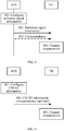
- FIG. 3 is a schematic flow chart of a channel measurement procedure according to an embodiment of the present invention.
- a UE is used to represent a user equipment, but the embodiment of the present invention is not limited to a specific system represented by the term. The embodiment of the present invention may be applied to any system similarly, and these applications all fall within the scope of the embodiment of the present invention.
- a base station eNB is used as a network device configuring a reference signal, to which the embodiment of the present invention is not limited.
- a reference signal may be configured through another network device, such as a radio network controller RNC (Radio Network Controller).
- RNC Radio Network Controller
- An eNB configures, for each frequency band of N frequency bands having a same carrier frequency, according to a measurement demand, reference signal information corresponding to each frequency band, so that reference signal densities included in configured reference signal information of at least two frequency bands of the N frequency bands are different.
- N is a positive integer greater than or equal to 2.
- the measurement demand may include a measurement precision demand, namely, to ensure that channel state information obtained through measurement is basically the same as actual channel state information, and may further include consideration for an overhead of a reference signal used for measurement, namely, to ensure that the overhead of the reference signal used for measurement is as small as possible, and may further include a demand for different measurement purposes, namely, to configure different reference signal information according to whether a reference signal is used for channel quality measurement or used for interference level measurement, where the reference signal information includes a reference signal density.
- a configured reference signal density may be low, and on the contrary, for a reference signal mainly used for interference level measurement, a configured reference signal density may be high.
- Each frequency band may be formed of one sub-carrier or more sub-carriers, or formed of one or more physical resource blocks PRB (Physical resource block), or formed of one or more resource block groups RBG (Resource block group).
- Each frequency band may also be the foregoing backward compatible carrier part, or the foregoing non-backward compatible carrier part (such as a carrier segment or carrier extension part).
- a plurality of sub-carriers (or PRB/RBG) may be consecutive, and may also be inconsecutive.
- the eNB configures reference signal information of different frequency bands in a same carrier for each UE, and each frequency band corresponds to a piece of reference signal information.
- the reference signal information refers to information required to generate a reference signal.
- the reference signal information includes a reference signal density, where reference signal densities included in reference signal information of at least two frequency bands are different.
- the reference signal may be a reference signal for performing channel quality measurement and/or interference level measurement, such as a CSI-RS, a CRS or a multicast service reference signal, or other reference signals which may perform channel quality measurement and/or interference level measurement.
- the reference signal density may be a distribution density on a time domain or a distribution density on a frequency domain of the reference signal or a pattern of the reference signal, and may also be a combination of these distribution densities.
- the distribution density on a time domain may be a time interval between two neighboring reference signal patterns or two neighboring reference signals in the time on a same frequency band, and the time interval may be one or more subframes, and may also be one or more radio frames; the distribution density on a time domain may further be a distribution period of a reference signal or a reference signal pattern on a time domain on a same frequency band; the reference signal pattern refers to a resource unit having same reference signal distribution, and the resource unit may be a PRB.
- the distribution density on a frequency domain may be a frequency interval between two neighboring reference signals or two neighboring reference signal patterns in the frequency on a same frequency band, and the frequency interval may be one or more subcarriers, may also be one or more PRBs, and may also be one or more RBGs.
- the eNB configures a distribution density of a reference signal on different frequency bands on the time domain, which may be that a time interval between two neighboring reference signals or two neighboring reference signal patterns in the time on a same frequency band may be directly defined, may also be implemented by configuring different reference signal periods or reference signal pattern periods, and may also be implemented by configuring a specific downlink subframe mode, where the specific downlink subframe mode corresponds to a reference signal density mode in a one-to-one manner.
- some uplink subframes may be used as downlink subframes, and in this case, a reference signal only occurs on the downlink subframe, namely, to keep consistent with a downlink subframe mode of the FDD UL frequency band;
- the eNB configures a distribution density of a reference signal on different frequency bands on the frequency domain, which may be that a frequency interval between two neighboring reference signals or two neighboring reference signal patterns in the frequency on a same frequency band may be directly defined.
- the reference signal information may further include reference signal transmit power control information, a bandwidth based on which a reference signal is generated, reference signal port information, reference signal location index information, and reference signal muting (Muting) mode information.
- the eNB notifies the UE of reference signal information corresponding to different frequency bands in a same carrier.
- the eNB may notify the user equipment of the reference signal information through a single piece of signaling carrying reference signal information corresponding to the N frequency bands; or the eNB may notify the user equipment of the reference signal information through N pieces of signaling, where each of the N pieces of signaling carries the reference signal information corresponding to each frequency band of the N frequency bands.
- the eNB may notify the reference signal information through RRC (radio resource control, Radio Resource Control) broadcast signaling, RRC dedicated signaling or physical layer signaling.
- RRC radio resource control, Radio Resource Control
- the eNB may notify the UE of reference signal density configurations of different frequency bands through user equipment-specific (UE-Specific) signaling or cell-specific (Cell-Specific) signaling or physical layer signaling.
- UE-Specific user equipment-specific
- Cell-Specific cell-specific
- SIB System Information Block
- the reference signal density may be a distribution period of the reference signal or the reference signal pattern on the time domain, may also be a frequency interval of the reference signal or the reference signal pattern on the frequency domain, and may also be a combination of the two.
- the reference signal information further includes a bandwidth based on which the reference signal is generated, so that the user equipment generates the reference signal according to the bandwidth, where the bandwidth is a bandwidth of a frequency band corresponding to the reference signal information, or a bandwidth of any one frequency band of the N frequency bands, or a maximum bandwidth in the N frequency bands, or a total bandwidth of K frequency bands of the N frequency bands, where K is a positive integer smaller than or equal to N.
- the eNB may further notify the UE of correspondence between the reference signal information and each frequency band of the N frequency bands, so that the user equipment acquires, according to the correspondence, reference signal information corresponding to each frequency band of the N frequency bands.
- 303 is an optional procedure. Correspondence between different reference signal information and different frequency bands may be implicit, and in this case, the procedure 303 of notifying the correspondence is not required. For example, when reference signal information corresponding to different frequency bands is borne in a same piece of signaling, a frequency band area on which the reference signal information acts may be determined through a sequence in which the reference signal information occurs in the signaling.
- 303 is shown after 302, but it imposes no limitation on the scope of the embodiment of the present invention.
- 303 may be included in 302, namely, the correspondence may be included in signaling that bears a reference signal information configuration and notified to the UE together.
- 303 may be executed after 302, may also be executed before 302, or executed in parallel with 302.
- the eNB may also not configure any reference signal on a part of frequency bands. Further, the eNB may also notify, through RRC broadcast signaling or RRC dedicated signaling or physical layer signaling, the UE of frequency bands configured with no reference signal, or the eNB may also configure reference signal densities included in reference signal information to be infinitely great, so as to indicate that a part of frequency bands are configured with no reference signal.
- the UE After receiving the reference signal information, the UE performs channel measurement according to the reference signal information.
- the channel measurement refers to that the user equipment generates a reference signal according to the reference signal information corresponding to each frequency band of the N frequency bands, and then measures a channel state between the network device and the user equipment by utilizing the reference signal, where the channel state includes channel quality and/or an interference level.
- the UE obtains reference signal information from the signaling sent by the eNB, where the reference signal information includes a reference signal density.
- the UE may also obtain correspondence between different reference signal information configurations and frequency bands from the signaling sent by the eNB, or the UE may also implicitly obtain a frequency band relationship corresponding to different reference signal information configurations, thereby determining reference signal information configurations corresponding to different frequency bands of a same carrier, and then measure channel state information of different frequency bands by utilizing the information.
- the UE In a case that the reference signal information notified in 302 further includes a bandwidth based on which a reference signal is generated, the UE generates a reference signal according to the bandwidth, and performs channel measurement by utilizing the reference signal, where the bandwidth is a bandwidth of a frequency band corresponding to the reference signal information, or a bandwidth of any one frequency band of the N frequency bands, or a maximum bandwidth in the N frequency bands, or a total bandwidth of K frequency bands of the N frequency bands, where K is a positive integer smaller than or equal to N.
- respective reference signal information is configured, so that reference signal densities included in reference signal information of at least two frequency bands are different, so that reference signal information can be designed pointedly according to different measurement demands of different frequency bands, and a reference signal overhead can be reduced in a case that reference signal measurement precision is ensured.
- FIG. 4 is a schematic flow chart of a channel measurement procedure according to another embodiment of the present invention.
- an adopted reference signal is a CSI-RS.
- an eNB configures a CSI-RS according to a measurement demand, for example, according to different channel states undergone by a UE on different frequency bands in a same carrier and different purposes based on CSI-RS measurement, so as to satisfy channel state measurement precision of different frequency bands and implement maximization of data resource utilization of different frequency bands.
- the eNB configures CSI-RS information corresponding to N frequency bands in a same carrier.
- the eNB configures CSI-RS information corresponding to different frequency bands in a same carrier for each UE according to a measurement demand, including: according to a channel state undergone by each UE on different frequency bands, such as a channel change speed, and different demands of a UE based on CSI-RS measurement, for example, one or more of frequency bands adopt a CSI-RS to perform channel quality measurement, and the other more or one of the frequency bands adopts a CSI-RS to perform channel quality and interference level measurement.
- the CSI-RS information may specifically include a reference signal density of a CSI-RS.
- CSI-RS information corresponding to at least one frequency band of N frequency bands further includes: CSI-RS location index information (such as symbol/frequency location), CSI-RS transmit power control information, CSI-RS port information (such as the number of antenna ports), and CSI-RS muting (muting) mode information.
- reference signal information corresponding to each frequency band may include the foregoing various types of information.
- at least one piece of the foregoing information is missing in reference signal information corresponding to at least one frequency band of N frequency bands, while reference signal information corresponding to other frequency bands includes the missing information.
- a distribution density of the CSI-RS may be a CSI-RS period (a type of reference signal density) and/or a CSI-RS frequency domain density (another type of reference signal density).
- CSI-RS information may be different for each UE, and may also be the same for each UE.
- CSI-RS configuration periods and/or CSI-RS frequency domain densities on at least two frequency bands are different.
- a specific CSI-RS information configuration may be implemented by adopting the following two manners:
- a CSI-RS period parameter on N-M1 frequency bands may adopt a configuration same as that of a CSI-RS period corresponding to one or more frequency bands of M1 frequency bands
- CSI-RS location index information on N-M2 frequency bands may adopt a configuration same as that of CSI-RS location index information corresponding to one or more frequency bands of M2 frequency bands
- CSI-RS transmit power information on N-M3 frequency bands may adopt a configuration same as that of CSI-RS transmit power information corresponding to one or more frequency bands of M3 frequency bands
- a corresponding CSI-RS distribution port on N-M4 frequency bands may adopt a configuration same as that of a CSI-RS distribution port corresponding to one or more frequency bands of M4 frequency bands
- a corresponding CSI-RS period parameter on N-M1 frequency bands may adopt a configuration same as that of a CSI-RS period corresponding to one or more frequency bands of M1 frequency bands
- CSI-RS location index information on N-M2 frequency bands may adopt a configuration same as
- N pieces of signaling may be further directly introduced and used to indicate CSI-RS information of N frequency bands, and the CSI-RS information may include: a CSI-RS period, CSI-RS location index information, CSI-RS transmit power control information, CSI-RS port information, a CSI-RS muting mode, and a CSI-RS frequency domain density. Meanings of these parameters are described in the foregoing.
- the eNB may include, in CSI-RS information, an effective frequency band area corresponding to the CSI-RS information (a correspondence indication manner) or notify an effective frequency band area corresponding to the CSI-RS information through other signaling (another correspondence indication manner), and the effective frequency band area corresponding to the CSI-RS information is used to indicate an effective frequency band on which current CSI-RS information acts.
- the indication information may adopt an explicit manner.
- an information field may be added in a CSI-RS configuration parameter, and used to indicate effectiveness of the CSI-RS configuration in different frequency bands, and the effectiveness of the CSI-RS configuration in different frequency bands may also be indicated through other signaling.
- the indication information may also adopt an implicit manner. Specifically, with respect to the manner 1, a first CSI-RS configuration parameter may be used for configuring CSI-RS information of a first frequency band, a second CSI-RS configuration parameter may be used for configuring CSI-RS information of a second frequency band, ..., and an N th CSI-RS configuration parameter may be used for configuring CSI-RS information of an N th frequency band.
- the CSI-RS information may further include a bandwidth based on which a CSI-RS is generated, so that the user equipment generates a CSI-RS according to the bandwidth, where the bandwidth is a bandwidth of a frequency band corresponding to the reference signal information, or a bandwidth of any one frequency band of the N frequency bands, or a maximum bandwidth in the N frequency bands, or a total bandwidth of K frequency bands of the N frequency bands, where K is a positive integer smaller than or equal to N.
- a CSI-RS distributed on the first frequency band may be generated according to a bandwidth of the first frequency band, and the rest may be deduced by analogy.
- Bandwidth information on which this CSI-RS generating sequence is based may be notified by the eNB to the UE, and the information may also be commonly known by the eNB and the UE in other manners, which is not limited here.
- the eNB may also not configure any CSI-RS on J frequency bands of N frequency bands, where J is a positive integer smaller than N.
- the eNB may make the UE acquire that the J frequency bands have no CSI-RS configuration by configuring a CSI-RS period on the J frequency bands to be infinitely great, or by configuring a CSI-RS frequency domain density on the J frequency bands to be infinitely great, or directly by notifying the UE through signaling, or in other manners.
- a channel quality indicator report parameter CQI-ReportConfig includes a precoding matrix index (Precoding Matrix Index, PMI)/rank index (Rank Index, RI) report parameter pmi-RI-Report
- PMI Precoding Matrix Index
- RI Rank Index
- an effective frequency domain range of the PMI/RI report parameter needs to be further illustrated.
- an explicit indication namely, action of the PMI/RI report parameter only on a frequency band part where a CRS and a CSI-RS exist simultaneously; or an explicit indication, namely, addition of an information field, is used to indicate the effective frequency domain range of the PMI/RI report parameter.
- the eNB notifies the UE of CSI-RS information of different frequency bands in a same carrier.
- the eNB may send CSI-RS modes of different frequency bands to the UE through user equipment-specific (UE-Specific) signaling or cell-specific (Cell-Specific) signaling or physical layer signaling.
- UE-Specific user equipment-specific
- Cell-Specific cell-specific
- notification may be given through broadcast signaling (MIB), and may also be given through system information block (System Information Block, SIB) signaling.
- MIB broadcast signaling
- SIB System Information Block
- the UE performs channel measurement according to CSI-RS information of different frequency bands.
- the UE receives signaling which bears CSI-RS information and is sent by the eNB, may identify CSI-RS information respectively corresponding to different frequency bands, then generate a CSI-RS by utilizing the information, and measure channel state information of different frequency bands by utilizing the generated CSI-RS.
- At least one piece of the following information may be missing in the CSI-RS information corresponding to the at least one frequency band of the N frequency bands: CSI-RS location index information, CSI-RS transmit power control information, CSI-RS port information and CSI-RS muting mode information.
- the missing information is obtained according to CSI-RS information corresponding to other frequency bands of the N frequency bands, where the CSI-RS information corresponding to the other frequency bands includes the missing information, and channel measurement is performed according to all reference signal information after the missing information is obtained.
- respective reference signal information is configured, so that reference signal densities included in reference signal information of at least two frequency bands are different, so that reference signal information can be designed pointedly according to different measurement demands of different frequency bands, and a reference signal overhead can be reduced in a case that reference signal measurement precision is ensured.
- FIG. 5 is a schematic flow chart of a channel measurement procedure according to another embodiment of the present invention.
- an adopted reference signal is a CRS.
- an eNB configures a CRS according to a measurement demand, for example, according to different demands of a UE on different frequency bands in a same carrier for CRS overheads, so as to satisfy channel state measurement precision of different frequency bands and maximize a data resource.
- the eNB configures CRS information corresponding to N frequency bands in a same carrier.
- the CRS information may specifically include a CRS reference signal density, and additionally, CRS information corresponding to at least one frequency band of N frequency bands may further include one or more pieces of the following information: CRS transmit power, and CRS port information (such as, the number of occupied antenna ports).
- CRS transmit power such as, the number of occupied antenna ports
- CRS port information such as, the number of occupied antenna ports
- reference signal information corresponding to each frequency band may include the foregoing various types of information.
- at least one piece of the foregoing information is missing in reference signal information corresponding to at least one frequency band of N frequency bands, while reference signal information corresponding to other frequency bands includes the missing information.
- the CRS reference signal density may be a distribution period of a CRS pattern (CRS pattern) on a time domain (a type of reference signal density) and/or a CRS frequency domain density (another type of reference signal density).
- CRS pattern a CRS pattern
- a certain configuration parameter not only may be different for each UE, but also may be the same for each UE.
- CRS pattern configuration periods and/or CRS frequency domain densities on at least two frequency bands are different, and other configuration parameters may be the same, and may also be different.
- a specific configuration mode may be implemented by adopting the following manners:
- an information field is added to indicate M9 types of different CRS transmit power, and is at least used to indicate CRS transmit power of M9 different frequency bands.
- an information field is added to indicate M10 types of different CRS port information, and is at least used to indicate CRS port information of M10 different frequency bands.
- M7/M8 is a positive integer not greater than N
- M9/M10 is an integer not greater than N and not smaller than zero.
- the distribution period of the CRS pattern and/or the CRS frequency domain density in the foregoing CRS configuration parameter may be set according to a requirement.
- the CRS pattern period is not 1 ms and/or the CRS frequency domain density is not 6 sub-carriers.
- a CRS pattern period on N-M7 frequency bands may adopt a configuration same as that of a CRS pattern period corresponding to one or more frequency bands of M7 frequency bands, and may also adopt a configuration of 1 ms by default;
- a CRS frequency domain density on N-M8 frequency bands may adopt a configuration same as that of CRS frequency domain density corresponding to one or more frequency bands of M8 frequency bands, and may also adopt a configuration of 6 sub-carriers by default;
- CRS transmit power on N-M9 frequency bands may adopt a configuration same as that of CRS transmit power corresponding to one or more frequency bands of M9 frequency bands, and may also adopt a configuration same as that of the prior art by default;
- CRS port information on N-M10 frequency bands may adopt a configuration same as that of CRS port information corresponding to one
- the eNB may further configure an effective frequency band area corresponding to CRS information (a correspondence indication manner), and the effective frequency band area corresponding to the CRS information is used to indicate an effective frequency band on which current CRS information acts.
- the indication information may adopt an explicit manner, and may also adopt an implicit manner. For a specific manner, reference may be made to the description in 401 of FIG. 4 , and details are not repeatedly described here.
- the CRS information may further include a bandwidth based on which a CRS is generated, so that the user equipment generates a CRS according to the bandwidth, where the bandwidth is a bandwidth of a frequency band corresponding to the reference signal information, or a bandwidth of any one frequency band of the N frequency bands, or a maximum bandwidth in the N frequency bands, or a total bandwidth of K frequency bands of the N frequency bands, where K is a positive integer smaller than or equal to N.
- a CRS distributed on the first frequency band may be generated according to a bandwidth of the first frequency band, and the rest may be deduced by analogy.
- Bandwidth information on which this CRS generating sequence is based may be notified by the eNB to the UE, and the information may also be commonly known by the eNB and the UE in other manners, which is not limited here.
- the eNB may also not configure any CRS on J frequency bands of N frequency bands, where J is a positive integer smaller than N.
- the eNB may make the UE acquire that the J frequency bands have no CRS configuration by configuring a CRS pattern period on the J frequency bands to be infinitely great and/or by configuring a CRS frequency domain density on the J frequency bands to be infinitely great, or directly by notifying the UE through signaling, or in other manners.
- a CRS pattern period not equal to 1 ms or a CRS frequency domain density not equal to 6 sub-carriers may also be applied to frequency bands of different carriers.
- a CRS configuration parameter of the first frequency band may continue to use an existing configuration, and a CRS configuration parameter of the second frequency band may be implemented through the foregoing manner.
- a CRS pattern period and/or a CRS frequency domain density in the CRS configuration parameter of the second frequency band are different from those of a CRS configuration of the first frequency band, that is, one of the following conditions is satisfied: the CRS pattern period is not 1 ms, and the CRS frequency domain density is not 6 sub-carriers.
- the eNB notifies the UE of CRS information of N frequency bands in a same carrier.
- the eNB may send CRS information of different frequency bands to the UE through user equipment-specific (UE-Specific) signaling or cell-specific (Cell-Specific) signaling or physical layer signaling.
- UE-Specific user equipment-specific
- Cell-Specific cell-specific
- notification may be given through broadcast signaling (MIB), and may also be given through system information block (System Information Block, SIB) signaling.
- MIB broadcast signaling
- SIB System Information Block
- the UE performs channel measurement according to CRS information of different frequency bands.
- the UE receives signaling which bears CRS information and is sent by the eNB, may identify CRS configurations respectively corresponding to different frequency bands, then generate a CRS by utilizing the information, and measure channel state information of different frequency bands by utilizing the generated CRS.
- At least one piece of the following information may be missing in the CRS information corresponding to the at least one frequency band of the N frequency bands: CRS port information and CRS transmit power information.
- the missing information is obtained according to CRS information corresponding to other frequency bands of the N frequency bands, where the CRS information corresponding to the other frequency bands includes the missing information, and channel measurement is performed according to all reference signal information after the missing information is obtained.
- a reference signal configuration can be separately performed according to different channel states undergone by a UE on different frequency bands in a same carrier and/or different purposes based on reference signal measurement and/or consideration for reference signal overhead demands of different frequency bands, so as to satisfy channel state measurement precision of different frequency bands and implement maximization of data resource utilization rates of different frequency bands.
- FIG. 6 is a schematic block diagram of a network device according to an embodiment of the present invention.
- a network device 600 in FIG. 6 may be, for example, a base station, a base station controller, a radio network controller, a mobility management entity, an access gateway, a multi-cell/multicast coordinated entity, and include a configuring unit 610 and a notifying unit 620.
- the configuring unit 610 configures, for each frequency band of N frequency bands having a same carrier frequency, according to a measurement demand, reference signal information corresponding to each frequency band, so that reference signal densities included in configured reference signal information of at least two frequency bands of the N frequency bands are different, where N is a positive integer greater than or equal to 2, the reference signal information refers to information required to generate a reference signal, the reference signal density refers to a distribution density on a time domain or a distribution density on a frequency domain of the reference signal or a pattern of the reference signal.
- the notifying unit 620 notifies a user equipment of the reference signal information configured by the configuring unit 610, so that the user equipment performs channel measurement according to the reference signal information.
- respective reference signal information is configured, so that reference signal densities included in reference signal information of at least two frequency bands are different, so that reference signal information can be designed pointedly according to different measurement demands of different frequency bands, and a reference signal overhead can be reduced in a case that reference signal measurement precision is ensured.
- a non-limiting example of the network device 600 in FIG. 6 is the base station (or the eNB) in FIG. 1 to FIG. 5 , which can execute each operation related to the network device in the method shown in FIG. 1 to FIG. 5 , so detailed description is appropriately omitted.
- the reference signal information configured by the configuring unit 610 further includes a bandwidth based on which the reference signal is generated, so that the user equipment generates the reference signal according to the bandwidth, where the bandwidth is a bandwidth of a frequency band corresponding to the reference signal information, or a bandwidth of any one frequency band of the N frequency bands, or a maximum bandwidth in the N frequency bands, or a total bandwidth of K frequency bands of the N frequency bands, where K is a positive integer smaller than or equal to N.
- each frequency band of the N frequency bands is formed of one or more sub-carriers, or formed of one or more physical resource blocks PRB, or formed of one or more resource block groups RBG.
- the notifying unit 620 may be further configured to notify the user equipment of correspondence between the reference signal information and each frequency band of the N frequency bands, so that the user equipment acquires, according to the correspondence, reference signal information corresponding to each frequency band of the N frequency bands.
- the reference signal may be a CSI-RS, a CRS or a multicast service reference signal.
- reference signal information which corresponds to at least one frequency band of the N frequency bands and is configured by the configuring unit 610 further includes: CSI-RS location index information, CSI-RS transmit power control information, CSI-RS port information and CSI-RS muting mode information.
- reference signal information which corresponds to at least one frequency band of the N frequency bands and is configured by the configuring unit 610 further includes the following CRS reference signal information: CRS port information and CRS transmit power information.
- the notifying unit 620 notifies reference signal information or the foregoing correspondence through a single piece of signaling or N pieces of signaling (such as, radio resource control broadcast signaling, RRC dedicated signaling or physical layer signaling).
- a notification manner may be explicit or implicit.
- FIG. 7 is a schematic block diagram of a user equipment according to an embodiment of the present invention.
- a user equipment 700 in FIG. 7 includes a receiving unit 710 and a measuring unit 720.
- the receiving unit 710 receives reference signal information which corresponds to each frequency band of N frequency bands and is notified by a network device, where the N frequency bands have a same carrier frequency, the reference signal information is configured for each frequency band by the network device according to a measurement demand, and reference signal densities included in configured reference signal information of at least two frequency bands of the N frequency bands are different, where N is a positive integer greater than or equal to 2, the reference signal information refers to information required to generate a reference signal, the reference signal density refers to a distribution density on a time domain or a distribution density on a frequency domain of the reference signal or a pattern of the reference signal.
- the measuring unit 720 performs channel measurement according to the reference signal information received by the receiving unit 710.
- respective reference signal information is configured, so that reference signal densities included in reference signal information of at least two frequency bands are different, so that reference signal information can be designed pointedly according to different measurement demands of different frequency bands, and a reference signal overhead can be reduced in a case that reference signal measurement precision is ensured.
- a non-limiting example of the user equipment 700 in FIG. 7 is the user equipment UE in FIG. 1 to FIG. 5 , which can execute each operation related to the user equipment in the method shown in FIG. 1 to FIG. 5 , so detailed description is appropriately omitted.
- the receiving unit 710 is further configured to receive correspondence which is between the reference signal information and each frequency band of the N frequency bands and is notified by the network device, and acquire, according to the correspondence, reference signal information corresponding to each frequency band of the N frequency bands.
- the measuring unit 720 When the reference signal information received by the receiving unit 710 further includes a bandwidth based on which the reference signal is generated, the measuring unit 720 generates the reference signal according to the bandwidth, and performs the channel measurement by utilizing the reference signal, where the bandwidth is a bandwidth of a frequency band corresponding to the reference signal information, or a bandwidth of any one frequency band of the N frequency bands, or a maximum bandwidth in the N frequency bands, or a total bandwidth of K frequency bands of the N frequency bands, where K is a positive integer smaller than or equal to N.
- the reference signal may be a CSI-RS, a CRS or a multicast service reference signal.
- the reference signal information which corresponds to each frequency band and is received by the receiving unit 710 may further include: CSI-RS location index information, CSI-RS transmit power control information, CSI-RS port information and CSI-RS muting mode information.
- the reference signal information which corresponds to each frequency band and is received by the receiving unit 710 may further include: CRS port information and CRS transmit power information.
- the measuring unit 720 may obtain the missing information according to reference signal information corresponding to other frequency bands, where the reference signal information corresponding to the other frequency bands includes the missing information, and perform channel measurement according to all reference signal information after obtaining the missing information.
- the measuring unit 720 obtains the missing information according to reference signal information corresponding to other frequency bands of the N frequency bands, where the reference signal information corresponding to the other frequency bands includes the missing information, and performs channel measurement according to all reference signal information after obtaining the missing information.
- the measuring unit 720 obtains the missing information according to reference signal information corresponding to other frequency bands of the N frequency bands, where the reference signal information corresponding to the other frequency bands includes the missing information, and performs channel measurement according to all reference signal information after obtaining the missing information.
- the receiving unit 710 may receive the reference signal information notified, through a single piece of signaling, by the network device, where the single piece of signaling carries reference signal information corresponding to the N frequency bands.
- the receiving unit 710 may receive the reference signal information notified, through N pieces of signaling, by the network device, where each of the N pieces of signaling carries the reference signal information corresponding to each frequency band of the N frequency bands.
- a communication system may include the network device 600 or the user equipment 700.
- the disclosed system, apparatus, and method may be implemented in other manners.
- the described apparatus embodiment is merely exemplary.
- dividing of the units is merely a type of logical function dividing, and there may be other dividing manners during actual implementation.
- a plurality of units or components may be combined or integrated into another system, or some features may be ignored or not performed.
- the shown or discussed mutual couplings or direct couplings or communication connections may be implemented through some interfaces.
- the indirect couplings or communication connections between the apparatuses or units may be implemented in electronic, mechanical, or other forms.
- the units described as separate parts may or may not be physically separated, and parts displayed as units may or may not be physical units, may be located in one position, or may be distributed on a plurality of network units. A part or all of the units may be selected according to actual needs to achieve the purposes of the solutions of the embodiments.
- each of the units may exist alone physically, and two or more units may also be integrated into one unit.
- the integrated unit may be implemented in a form of hardware, and may also be implemented in a form of a software functional unit.
- the integrated unit When the integrated unit is implemented in a form of a software functional unit and sold or used as an independent product, the integrated unit may be stored in a computer-readable storage medium.
- the computer software product is stored in a storage medium, and includes several instructions for instructing a computer device (which may be a personal computer, a server, or a network device, or the like) to perform all or a part of the steps of the methods described in the embodiments of the present invention.
- the foregoing storage medium includes: any medium that is capable of storing program codes, such as a USB flash disk, a removable hard disk, a read-only memory (ROM, Read-Only Memory), a random access memory (RAM, Random Access Memory), a magnetic disk, or an optical disk.
- program codes such as a USB flash disk, a removable hard disk, a read-only memory (ROM, Read-Only Memory), a random access memory (RAM, Random Access Memory), a magnetic disk, or an optical disk.
Landscapes
- Engineering & Computer Science (AREA)
- Signal Processing (AREA)
- Computer Networks & Wireless Communication (AREA)
- Mobile Radio Communication Systems (AREA)
Claims (12)
- Kanalmessverfahren, umfassend:Konfigurieren (101) von Bezugssignalinformationen, die jedem Frequenzband aus N Frequenzbändern entsprechen, die eine gleiche Trägerfrequenz aufweisen, für jedes Frequenzband gemäß einer Messanforderung, sodass die Bezugssignaldichten, die in den konfigurierten Bezugssignalinformationen von mindestens zwei Frequenzbändern der N Frequenzbänder enthalten sind, unterschiedlich sind,wobei N eine positive ganze Zahl größer als oder gleich 2 ist, wobei sich die Bezugssignalinformationen auf Informationen beziehen, die erforderlich sind, um ein Bezugssignal zu erzeugen, wobei sich die Bezugssignaldichte auf eine Verteilungsdichte in einem Zeitbereich oder eine Verteilungsdichte in einem Frequenzbereich des Bezugssignals bezieht;Benachrichtigen (102) der Bezugssignalinformationen an ein Benutzergerät, sodass das Benutzergerät eine Kanalmessung gemäß den Bezugssignalinformationen ausführt;dadurch gekennzeichnet, dass
das Bezugssignal ein Bezugssignal zum Ausführen entweder einer Kanalqualitätsmessung oder einer Störpegelmessung ist;
wobei die Messanforderung eine Anforderung für verschiedene Messzwecke umfasst, um zu konfigurieren, ob das Bezugssignal für eine Kanalqualitätsmessung oder für eine Störungsmessung verwendet wird. - Verfahren nach Anspruch 1, wobei das Verfahren nach dem Konfigurieren der jedem Frequenzband entsprechenden Bezugssignalinformationen gemäß einer Messanforderung, außerdem umfasst:Benachrichtigen einer Entsprechung zwischen den Bezugssignalinformationen und jedem Frequenzband der N Frequenzbänder an das Benutzergerät, sodass das Benutzergerät gemäß der Entsprechung Bezugssignalinformationen erfasst, die jedem Frequenzband der N Frequenzbänder entsprechen.
- Verfahren nach Anspruch 1, wobei die Bezugssignalinformationen außerdem eine Bandbreite umfassen, auf deren Grundlage das Bezugssignal erzeugt wird, sodass das Benutzergerät das Bezugssignal gemäß der Bandbreite erzeugt, wobei die Bandbreite eine Bandbreite eines Frequenzbands ist, das den Bezugssignalinformationen entspricht, oder eine Bandbreite von einem beliebigen Frequenzband der N Frequenzbänder ist oder eine maximale Bandbreite in den N Frequenzbändern ist oder eine Gesamtbandbreite von K Frequenzbändern aus den N Frequenzbändern ist, wobei K eine positive ganze Zahl ist, die kleiner als oder gleich N ist.
- Kanalmessverfahren, umfassend:Empfangen (201) von Bezugssignalinformationen, die jedem Frequenzband aus N Frequenzbändern entsprechen und die von einer Netzwerkvorrichtung benachrichtigt werden, wobei die N Frequenzbänder eine gleiche Trägerfrequenz aufweisen, wobei die Bezugssignalinformationen durch die Netzwerkvorrichtung für jedes Frequenzband gemäß einer Messanforderung konfiguriert sind und wobei Bezugssignaldichten, die in konfigurierten Bezugssignalinformationen von mindestens zwei Frequenzbändern der N Frequenzbänder enthalten sind, unterschiedlich sind,wobei N eine positive ganze Zahl größer als oder gleich 2 ist, wobei sich die Bezugssignalinformationen auf Informationen beziehen, die erforderlich sind, um ein Bezugssignal zu erzeugen, wobei sich die Bezugssignaldichte auf eine Verteilungsdichte in einem Zeitbereich oder eine Verteilungsdichte in einem Frequenzbereich des Bezugssignals bezieht;Ausführen (202) einer Kanalmessung gemäß den Bezugssignalinformationen;dadurch gekennzeichnet, dass
das Bezugssignal ein Bezugssignal zum Ausführen entweder einer Kanalqualitätsmessung oder einer Störpegelmessung ist;
wobei die Messanforderung eine Anforderung für verschiedene Messzwecke umfasst, um zu konfigurieren, ob das Bezugssignal für eine Kanalqualitätsmessung oder für eine Störungsmessung verwendet wird. - Verfahren nach Anspruch 4, wobei das Verfahren vor dem Ausführen der Kanalmessung gemäß den Bezugssignalinformationen außerdem umfasst:Empfangen einer Entsprechung zwischen den durch die Netzwerkvorrichtung benachrichtigten Bezugssignalinformationen und jedem Frequenzband der N Frequenzbänder; undErfassen der Bezugssignalinformationen gemäß der Entsprechung, wobei die Bezugssignalinformationen jedem Frequenzband der N Frequenzbänder entsprechen.
- Verfahren nach Anspruch 4, wobei die Bezugssignalinformationen außerdem eine Bandbreite umfassen, aufgrund der das Bezugssignal erzeugt wird; und
wobei das Ausführen der Kanalmessung gemäß den Bezugssignalinformationen umfasst:Erzeugen des Bezugssignals gemäß der Bandbreite; undAusführen der Kanalmessung, indem das Bezugssignal verwendet wird,wobei die Bandbreite eine Bandbreite eines Frequenzbands ist, das den Bezugssignalinformationen entspricht, oder eine Bandbreite von einem beliebigen Frequenzband der N Frequenzbänder ist oder eine maximale Bandbreite in den N Frequenzbändern ist oder eine Gesamtbandbreite von K Frequenzbändern aus den N Frequenzbändern ist, wobei K eine positive ganze Zahl ist, die kleiner als oder gleich N ist. - Netzwerkvorrichtung (600), umfassend:eine Konfiguriereinheit (610), die konfiguriert ist zum Konfigurieren von Bezugssignalinformationen, die jedem Frequenzband aus N Frequenzbändern entsprechen, die eine gleiche Trägerfrequenz aufweisen, für jedes Frequenzband gemäß einer Messanforderung, sodass die Bezugssignaldichten, die in den konfigurierten Bezugssignalinformationen von mindestens zwei Frequenzbändern der N Frequenzbänder enthalten sind, unterschiedlich sind, wobei N eine positive ganze Zahl größer als oder gleich 2 ist, wobei sich die Bezugssignalinformationen auf Informationen beziehen, die erforderlich sind, um ein Bezugssignal zu erzeugen, wobei sich die Bezugssignaldichte auf eine Verteilungsdichte in einem Zeitbereich oder eine Verteilungsdichte in einem Frequenzbereich des Bezugssignals bezieht;eine Benachrichtigungseinheit (620), die konfiguriert ist zum Benachrichtigen der Bezugssignalinformationen, die von der Konfiguriereinheit konfiguriert wurden, an ein Benutzergerät, sodass das Benutzergerät eine Kanalmessung gemäß den Bezugssignalinformationen ausführt;dadurch gekennzeichnet, dass
die Benachrichtigungseinheit (620) konfiguriert ist zum Benachrichtigen der Bezugssignalinformationen, die von der Konfiguriereinheit (610) konfiguriert wurden, an ein Benutzergerät, sodass das Benutzergerät eine Kanalmessung gemäß den Bezugssignalinformationen ausführt;
wobei das Bezugssignal ein Bezugssignal zum Ausführen entweder einer Kanalqualitätsmessung oder einer Störpegelmessung ist; und
wobei die Messanforderung eine Anforderung für verschiedene Messzwecke umfasst, um zu konfigurieren, ob das Bezugssignal für eine Kanalqualitätsmessung oder für eine Störungsmessung verwendet wird. - Netzwerkvorrichtung nach Anspruch 7, wobei die Benachrichtigungseinheit außerdem konfiguriert ist zum: Benachrichtigen einer Entsprechung zwischen den Bezugssignalinformationen und jedem Frequenzband der N Frequenzbänder an das Benutzergerät, sodass das Benutzergerät gemäß der Entsprechung Bezugssignalinformationen erfasst, die jedem Frequenzband der N Frequenzbänder entsprechen.
- Netzwerkvorrichtung nach Anspruch 7, wobei die Bezugssignalinformationen, die von der Konfiguriereinheit konfiguriert wurden, außerdem eine Bandbreite umfassen, auf deren Grundlage das Bezugssignal erzeugt wird, sodass das Benutzergerät das Bezugssignal gemäß der Bandbreite erzeugt, wobei die Bandbreite eine Bandbreite eines Frequenzbands ist, das den Bezugssignalinformationen entspricht, oder eine Bandbreite von einem beliebigen Frequenzband der N Frequenzbänder ist oder eine maximale Bandbreite in den N Frequenzbändern ist oder eine Gesamtbandbreite von K Frequenzbändern aus den N Frequenzbändern ist, wobei K eine positive ganze Zahl ist, die kleiner als oder gleich N ist.
- Benutzergerät (700), umfassend:eine Empfangseinheit (710), die konfiguriert ist zum Empfangen von Bezugssignalinformationen, die jedem Frequenzband aus N Frequenzbändern entsprechen und die von einer Netzwerkvorrichtung benachrichtigt werden, wobei die N Frequenzbänder eine gleiche Trägerfrequenz aufweisen, wobei die Bezugssignalinformationen durch die Netzwerkvorrichtung für jedes Frequenzband gemäß einer Messanforderung konfiguriert sind und wobei Bezugssignaldichten, die in den konfigurierten Bezugssignalinformationen von mindestens zwei Frequenzbändern der N Frequenzbänder enthalten sind, unterschiedlich sind, wobei N eine positive ganze Zahl größer als oder gleich 2 ist, wobei sich die Bezugssignalinformationen auf Informationen beziehen, die erforderlich sind, um ein Bezugssignal zu erzeugen, wobei sich die Bezugssignaldichte auf eine Verteilungsdichte in einem Zeitbereich oder eine Verteilungsdichte in einem Frequenzbereich des Bezugssignals bezieht;eine Messeinheit (720), die konfiguriert ist zum Ausführen einer Kanalmessung gemäß den von der Empfangseinheit empfangenen Bezugssignalinformationen;dadurch gekennzeichnet, dass
die Messeinheit (720) konfiguriert ist zum Ausführen einer Kanalmessung gemäß den von der Empfangseinheit (710) empfangenen Bezugssignalinformationen;
wobei das Bezugssignal ein Bezugssignal zum Ausführen entweder einer Kanalqualitätsmessung oder einer Störpegelmessung ist;
wobei die Messanforderung eine Anforderung für verschiedene Messzwecke umfasst, um zu konfigurieren, ob das Bezugssignal für eine Kanalqualitätsmessung oder für eine Störungsmessung verwendet wird. - Benutzergerät nach Anspruch 10, wobei
die Empfangseinheit außerdem konfiguriert ist zum Empfangen einer Entsprechung, die zwischen den Bezugssignalinformationen und jedem Frequenzband der N Frequenzbänder besteht und von der Netzwerkvorrichtung benachrichtigt wird, und zum Erfassen der Bezugssignalinformationen gemäß der Entsprechung, wobei die Bezugssignalinformationen jedem Frequenzband der N Frequenzbänder entsprechen. - Benutzergerät nach Anspruch 10, wobei
die von der Empfangseinheit empfangenen Bezugssignalinformationen außerdem eine Bandbreite umfassen, aufgrund der das Bezugssignal erzeugt wird; und die Messeinheit ein Bezugssignal gemäß der Bandbreite erzeugt und die Kanalmessung ausführt, indem das Bezugssignal verwendet wird,
wobei die Bandbreite eine Bandbreite eines Frequenzbands ist, das den Bezugssignalinformationen entspricht, oder eine Bandbreite von einem beliebigen Frequenzband der N Frequenzbänder ist oder eine maximale Bandbreite in den N Frequenzbändern ist oder eine Gesamtbandbreite von K Frequenzbändern aus den N Frequenzbändern ist, wobei K eine positive ganze Zahl ist, die kleiner als oder gleich N ist.
Applications Claiming Priority (2)
| Application Number | Priority Date | Filing Date | Title |
|---|---|---|---|
| CN201110118188.6A CN102780532B (zh) | 2011-05-09 | 2011-05-09 | 信道测量的方法及装置 |
| PCT/CN2012/075104 WO2012152206A1 (zh) | 2011-05-09 | 2012-05-04 | 信道测量的方法及装置 |
Publications (3)
| Publication Number | Publication Date |
|---|---|
| EP2698935A1 EP2698935A1 (de) | 2014-02-19 |
| EP2698935A4 EP2698935A4 (de) | 2014-04-16 |
| EP2698935B1 true EP2698935B1 (de) | 2016-12-07 |
Family
ID=47125304
Family Applications (1)
| Application Number | Title | Priority Date | Filing Date |
|---|---|---|---|
| EP12782417.5A Active EP2698935B1 (de) | 2011-05-09 | 2012-05-04 | Kanalmessverfahren und -vorrichtung |
Country Status (4)
| Country | Link |
|---|---|
| US (1) | US9191845B2 (de) |
| EP (1) | EP2698935B1 (de) |
| CN (1) | CN102780532B (de) |
| WO (1) | WO2012152206A1 (de) |
Families Citing this family (44)
| Publication number | Priority date | Publication date | Assignee | Title |
|---|---|---|---|---|
| US9184889B2 (en) * | 2012-08-08 | 2015-11-10 | Blackberry Limited | Method and system having reference signal design for new carrier types |
| US9402256B2 (en) | 2012-08-08 | 2016-07-26 | Blackberry Limited | Method and system having reference signal design for new carrier types |
| CN103856960B (zh) * | 2012-11-30 | 2016-11-02 | 展讯通信(天津)有限公司 | 通信终端及长期演进系统中小区测量的方法与装置 |
| CN103347298B (zh) | 2012-12-31 | 2019-02-19 | 上海华为技术有限公司 | 参考信号配置方法和参考信号发送方法及相关设备 |
| CN103281700A (zh) * | 2013-05-02 | 2013-09-04 | 苏州维特比信息技术有限公司 | 一种新类型载波的配置方法、基站及用户终端 |
| JP2016536928A (ja) * | 2013-09-25 | 2016-11-24 | エヌイーシー(チャイナ)カンパニー, リミテッドNEC(China)Co.,Ltd. | 無線通信システムにおけるアップリンク・データ送信のための方法及び装置 |
| CN104796232A (zh) * | 2014-01-18 | 2015-07-22 | 上海朗帛通信技术有限公司 | 一种在非授权频谱上的传输方法和装置 |
| CN106464461A (zh) * | 2014-05-15 | 2017-02-22 | 诺基亚通信公司 | 用于发射和/或接收参考信号的方法和装置 |
| CN104183074B (zh) * | 2014-08-29 | 2016-06-01 | 武汉理工光科股份有限公司 | 基于时域反射技术的分布式周界系统信号增强方法及系统 |
| US11581999B2 (en) * | 2014-10-08 | 2023-02-14 | Qualcomm Incorporated | Reference signal design for wireless communications |
| CN105743606A (zh) * | 2014-12-09 | 2016-07-06 | 深圳市中兴微电子技术有限公司 | 下行参考信号的调整方法及装置 |
| ES2927380T3 (es) * | 2015-05-12 | 2022-11-04 | Nec Corp | Método y aparato para la configuración de patrón de transmisión y detección de señales |
| CN108141333B (zh) * | 2015-09-25 | 2021-01-22 | 瑞典爱立信有限公司 | 用于处理无线通信网络中的信号测量的方法和通信终端 |
| US10278180B2 (en) * | 2016-01-15 | 2019-04-30 | Qualcomm Incorporated | Raster design for narrowband operation for machine type communications |
| US10382179B2 (en) | 2016-02-29 | 2019-08-13 | British Telecommunications Public Limited Company | Adapting reference signal density |
| US10491350B2 (en) | 2016-02-29 | 2019-11-26 | British Telecommunications Public Limited Company | Adaptive reference signal patterns |
| CN108781150B (zh) * | 2016-02-29 | 2019-09-10 | 英国电讯有限公司 | 控制自适应参考信号模式的装置、方法和计算机可读介质 |
| CN110289941B (zh) | 2016-03-16 | 2022-06-28 | 华为技术有限公司 | 数据发送方法、数据接收方法、发送端设备及接收端设备 |
| EP3437357B1 (de) * | 2016-04-01 | 2019-12-04 | Telefonaktiebolaget LM Ericsson (PUBL) | Verfahren und vorrichtungen zum steuern der messbandbreite zur berücksichtigung von störungen |
| US11368963B2 (en) * | 2016-09-21 | 2022-06-21 | Apple Inc. | Reduced CSI (channel state information)-RS (reference signal) density support for FD (full dimensional)-MIMO (multiple input multiple output) systems |
| CN108242987B (zh) * | 2016-12-23 | 2022-09-13 | 中兴通讯股份有限公司 | 参考信号发送方法及基站,配置确定方法及终端 |
| CN108282281B (zh) * | 2017-01-05 | 2020-02-21 | 中国移动通信有限公司研究院 | 一种信号配置方法及装置 |
| CN108616300B (zh) * | 2017-01-06 | 2024-03-08 | 华为技术有限公司 | 一种信道状态信息测量的配置方法及相关设备 |
| CN115834010B (zh) * | 2017-01-06 | 2024-09-20 | 中兴通讯股份有限公司 | 控制信道参考信号发送、接收方法及装置、基站、终端 |
| CN110169002B (zh) * | 2017-01-09 | 2021-11-30 | Lg 电子株式会社 | 无线通信系统中发送参考信号的方法及其装置 |
| CN115395998A (zh) * | 2017-05-04 | 2022-11-25 | 大唐移动通信设备有限公司 | 一种消息解码方法、发送端和接收端 |
| US11057800B2 (en) * | 2017-05-04 | 2021-07-06 | Qualcomm Incorporated | Neighbor cell measurement and reselection for narrowband operation |
| CN108809576B (zh) | 2017-05-05 | 2023-10-24 | 华为技术有限公司 | 参考信号的指示方法和装置 |
| ES2929774T3 (es) | 2017-05-26 | 2022-12-01 | Beijing Xiaomi Mobile Software Co Ltd | Dispositivo y método de medición de movilidad, y medio de almacenamiento legible por ordenador |
| CN109429338B (zh) * | 2017-08-24 | 2024-03-05 | 株式会社电装 | 频带指示方法、频带确定方法、发射端设备和接收端设备 |
| JP6867256B2 (ja) * | 2017-08-25 | 2021-04-28 | 株式会社日立製作所 | 磁気共鳴撮像装置及び画像処理方法 |
| JP7094673B2 (ja) * | 2017-09-08 | 2022-07-04 | シャープ株式会社 | 基地局装置、端末装置、および、通信方法 |
| CN110176981B (zh) | 2017-11-17 | 2020-06-26 | 华为技术有限公司 | 参考信号的传输方法和传输装置 |
| WO2019157737A1 (zh) | 2018-02-14 | 2019-08-22 | 华为技术有限公司 | 传输参考信号的方法及设备 |
| CN110198207B (zh) * | 2018-02-26 | 2020-09-15 | 维沃移动通信有限公司 | 无线通信的方法和网络设备 |
| JP7756071B2 (ja) * | 2019-08-02 | 2025-10-17 | サムスン エレクトロニクス カンパニー リミテッド | 非接続モード端末のための周波数測定設定方法と周波数測定を行う方法及び装置 |
| US11569961B2 (en) * | 2019-08-30 | 2023-01-31 | Huawei Technologies Co., Ltd. | Reference signaling overhead reduction apparatus and methods |
| CN114466442B (zh) * | 2020-11-10 | 2024-10-29 | 华为技术有限公司 | 一种侧行链路的数据传输方法及相关装置 |
| BR112023025768A2 (pt) * | 2021-06-11 | 2024-02-27 | Interdigital Patent Holdings Inc | Métodos, arquiteturas, aparelhos e sistemas direcionados à configuração de sinal de referência adaptável |
| CN115913503A (zh) * | 2022-04-12 | 2023-04-04 | 中兴通讯股份有限公司 | 一种参考信号传输方法、电子设备和存储介质 |
| WO2024020718A1 (en) | 2022-07-25 | 2024-02-01 | Zte Corporation | Reference signals with different resource densities |
| CN120693814A (zh) * | 2023-02-24 | 2025-09-23 | 华为技术有限公司 | 一种参考信号配置方法及通信装置 |
| CN119449245B (zh) * | 2023-08-01 | 2026-01-06 | 中国移动通信有限公司研究院 | 信号配置方法、装置、终端及网络侧设备 |
| WO2026007704A1 (en) * | 2024-07-04 | 2026-01-08 | Mediatek Inc. | Full duplex device-to-device communication csi and pmi signaling framework based on ue measurement and feedback |
Family Cites Families (5)
| Publication number | Priority date | Publication date | Assignee | Title |
|---|---|---|---|---|
| KR101265632B1 (ko) * | 2006-12-12 | 2013-05-22 | 엘지전자 주식회사 | 참조 신호 전송, 참조 신호 전송 패턴 설정, 자원 블록설정 및 할당을 위한 방법 및 장치 |
| EP2297980B1 (de) * | 2008-06-24 | 2018-08-29 | Mitsubishi Electric Corporation | Antennenauswahl mit klangreferenzsignalen mit wechselnder frequenz |
| BRPI1007299A8 (pt) * | 2009-01-29 | 2017-07-11 | Panasonic Corp | Método para mapeamento de sinais de referência e aparelho de estação base de comunicação sem fio |
| CN101932014A (zh) * | 2009-06-23 | 2010-12-29 | 中兴通讯股份有限公司 | 载波聚合中测量配置的处理方法 |
| CN102036264B (zh) | 2009-09-30 | 2013-12-04 | 华为技术有限公司 | 对小区进行信道测量的方法和装置 |
-
2011
- 2011-05-09 CN CN201110118188.6A patent/CN102780532B/zh active Active
-
2012
- 2012-05-04 WO PCT/CN2012/075104 patent/WO2012152206A1/zh not_active Ceased
- 2012-05-04 EP EP12782417.5A patent/EP2698935B1/de active Active
-
2013
- 2013-11-01 US US14/069,826 patent/US9191845B2/en active Active
Non-Patent Citations (1)
| Title |
|---|
| None * |
Also Published As
| Publication number | Publication date |
|---|---|
| WO2012152206A1 (zh) | 2012-11-15 |
| CN102780532A (zh) | 2012-11-14 |
| EP2698935A1 (de) | 2014-02-19 |
| CN102780532B (zh) | 2016-06-08 |
| US9191845B2 (en) | 2015-11-17 |
| EP2698935A4 (de) | 2014-04-16 |
| US20140086085A1 (en) | 2014-03-27 |
Similar Documents
| Publication | Publication Date | Title |
|---|---|---|
| EP2698935B1 (de) | Kanalmessverfahren und -vorrichtung | |
| US11336419B2 (en) | Reference signal measurement method, reference signal sending method, and related device | |
| US11044065B2 (en) | Method and apparatus for transmitting and receiving feedback information in mobile communication system using multiple antennas | |
| EP3391555B1 (de) | Schema zum konfigurieren eines referenzsignals und von kommunikationskanalstatusinformationen in einem drahtloskommunikationssystem mit mehreren antennenports | |
| EP4030676B1 (de) | Verfahren und vorrichtung zum senden und empfangen eines referenzsignals | |
| EP2701423B1 (de) | Verfahren und vorrichtung zur interferenzmessung in einer koordinierten mehrpunktübertragung | |
| KR101710204B1 (ko) | 다중 입출력 통신 시스템에서 채널측정을 위한 기준신호의 전송 방법 및 그 장치 | |
| EP2566219B1 (de) | Verfahren, system und vorrichtung zur interferenzmessung | |
| EP3402087B1 (de) | Verfahren zur meldung von kanalstatusinformationen, benutzergerät und basisstation | |
| EP2995113B1 (de) | Messungen in einem drahtlosen system | |
| EP3309974A1 (de) | Verfahren und vorrichtung zur übertragung von kanalstatusinformationen in einem drahtloskommunikationssystem | |
| CN102883341A (zh) | 信道信息的测量方法和相关装置 | |
| EP2982048A1 (de) | Kommunikationssystem | |
| WO2018033148A1 (en) | A method to transmit channel state information reference signals in large mimo systems | |
| US10097251B2 (en) | Wireless communication system, method for transmitting information of user equipment, method for receiving information of base station, and user equipment and base station thereof | |
| WO2022205407A1 (en) | Configuration of sounding reference signals based on user equipment reporting | |
| EP3878223B1 (de) | Verfahren und benutzergerät zur übertragung von referenzsymbolen |
Legal Events
| Date | Code | Title | Description |
|---|---|---|---|
| PUAI | Public reference made under article 153(3) epc to a published international application that has entered the european phase |
Free format text: ORIGINAL CODE: 0009012 |
|
| 17P | Request for examination filed |
Effective date: 20131114 |
|
| AK | Designated contracting states |
Kind code of ref document: A1 Designated state(s): AL AT BE BG CH CY CZ DE DK EE ES FI FR GB GR HR HU IE IS IT LI LT LU LV MC MK MT NL NO PL PT RO RS SE SI SK SM TR |
|
| A4 | Supplementary search report drawn up and despatched |
Effective date: 20140314 |
|
| RIC1 | Information provided on ipc code assigned before grant |
Ipc: H04B 17/00 20060101AFI20140310BHEP Ipc: H04L 25/02 20060101ALI20140310BHEP Ipc: H04L 5/00 20060101ALI20140310BHEP |
|
| DAX | Request for extension of the european patent (deleted) | ||
| 17Q | First examination report despatched |
Effective date: 20150205 |
|
| GRAP | Despatch of communication of intention to grant a patent |
Free format text: ORIGINAL CODE: EPIDOSNIGR1 |
|
| INTG | Intention to grant announced |
Effective date: 20160617 |
|
| GRAS | Grant fee paid |
Free format text: ORIGINAL CODE: EPIDOSNIGR3 |
|
| STAA | Information on the status of an ep patent application or granted ep patent |
Free format text: STATUS: GRANT OF PATENT IS INTENDED |
|
| GRAA | (expected) grant |
Free format text: ORIGINAL CODE: 0009210 |
|
| STAA | Information on the status of an ep patent application or granted ep patent |
Free format text: STATUS: THE PATENT HAS BEEN GRANTED |
|
| AK | Designated contracting states |
Kind code of ref document: B1 Designated state(s): AL AT BE BG CH CY CZ DE DK EE ES FI FR GB GR HR HU IE IS IT LI LT LU LV MC MK MT NL NO PL PT RO RS SE SI SK SM TR |
|
| REG | Reference to a national code |
Ref country code: GB Ref legal event code: FG4D |
|
| REG | Reference to a national code |
Ref country code: CH Ref legal event code: EP Ref country code: AT Ref legal event code: REF Ref document number: 852524 Country of ref document: AT Kind code of ref document: T Effective date: 20161215 |
|
| REG | Reference to a national code |
Ref country code: IE Ref legal event code: FG4D |
|
| REG | Reference to a national code |
Ref country code: DE Ref legal event code: R096 Ref document number: 602012026342 Country of ref document: DE |
|
| PG25 | Lapsed in a contracting state [announced via postgrant information from national office to epo] |
Ref country code: LV Free format text: LAPSE BECAUSE OF FAILURE TO SUBMIT A TRANSLATION OF THE DESCRIPTION OR TO PAY THE FEE WITHIN THE PRESCRIBED TIME-LIMIT Effective date: 20161207 |
|
| REG | Reference to a national code |
Ref country code: LT Ref legal event code: MG4D |
|
| REG | Reference to a national code |
Ref country code: NL Ref legal event code: MP Effective date: 20161207 |
|
| PG25 | Lapsed in a contracting state [announced via postgrant information from national office to epo] |
Ref country code: GR Free format text: LAPSE BECAUSE OF FAILURE TO SUBMIT A TRANSLATION OF THE DESCRIPTION OR TO PAY THE FEE WITHIN THE PRESCRIBED TIME-LIMIT Effective date: 20170308 Ref country code: LT Free format text: LAPSE BECAUSE OF FAILURE TO SUBMIT A TRANSLATION OF THE DESCRIPTION OR TO PAY THE FEE WITHIN THE PRESCRIBED TIME-LIMIT Effective date: 20161207 Ref country code: NO Free format text: LAPSE BECAUSE OF FAILURE TO SUBMIT A TRANSLATION OF THE DESCRIPTION OR TO PAY THE FEE WITHIN THE PRESCRIBED TIME-LIMIT Effective date: 20170307 Ref country code: SE Free format text: LAPSE BECAUSE OF FAILURE TO SUBMIT A TRANSLATION OF THE DESCRIPTION OR TO PAY THE FEE WITHIN THE PRESCRIBED TIME-LIMIT Effective date: 20161207 |
|
| REG | Reference to a national code |
Ref country code: AT Ref legal event code: MK05 Ref document number: 852524 Country of ref document: AT Kind code of ref document: T Effective date: 20161207 |
|
| PG25 | Lapsed in a contracting state [announced via postgrant information from national office to epo] |
Ref country code: FI Free format text: LAPSE BECAUSE OF FAILURE TO SUBMIT A TRANSLATION OF THE DESCRIPTION OR TO PAY THE FEE WITHIN THE PRESCRIBED TIME-LIMIT Effective date: 20161207 Ref country code: ES Free format text: LAPSE BECAUSE OF FAILURE TO SUBMIT A TRANSLATION OF THE DESCRIPTION OR TO PAY THE FEE WITHIN THE PRESCRIBED TIME-LIMIT Effective date: 20161207 Ref country code: HR Free format text: LAPSE BECAUSE OF FAILURE TO SUBMIT A TRANSLATION OF THE DESCRIPTION OR TO PAY THE FEE WITHIN THE PRESCRIBED TIME-LIMIT Effective date: 20161207 Ref country code: RS Free format text: LAPSE BECAUSE OF FAILURE TO SUBMIT A TRANSLATION OF THE DESCRIPTION OR TO PAY THE FEE WITHIN THE PRESCRIBED TIME-LIMIT Effective date: 20161207 |
|
| PG25 | Lapsed in a contracting state [announced via postgrant information from national office to epo] |
Ref country code: NL Free format text: LAPSE BECAUSE OF FAILURE TO SUBMIT A TRANSLATION OF THE DESCRIPTION OR TO PAY THE FEE WITHIN THE PRESCRIBED TIME-LIMIT Effective date: 20161207 |
|
| PG25 | Lapsed in a contracting state [announced via postgrant information from national office to epo] |
Ref country code: RO Free format text: LAPSE BECAUSE OF FAILURE TO SUBMIT A TRANSLATION OF THE DESCRIPTION OR TO PAY THE FEE WITHIN THE PRESCRIBED TIME-LIMIT Effective date: 20161207 Ref country code: EE Free format text: LAPSE BECAUSE OF FAILURE TO SUBMIT A TRANSLATION OF THE DESCRIPTION OR TO PAY THE FEE WITHIN THE PRESCRIBED TIME-LIMIT Effective date: 20161207 Ref country code: SK Free format text: LAPSE BECAUSE OF FAILURE TO SUBMIT A TRANSLATION OF THE DESCRIPTION OR TO PAY THE FEE WITHIN THE PRESCRIBED TIME-LIMIT Effective date: 20161207 Ref country code: CZ Free format text: LAPSE BECAUSE OF FAILURE TO SUBMIT A TRANSLATION OF THE DESCRIPTION OR TO PAY THE FEE WITHIN THE PRESCRIBED TIME-LIMIT Effective date: 20161207 Ref country code: IS Free format text: LAPSE BECAUSE OF FAILURE TO SUBMIT A TRANSLATION OF THE DESCRIPTION OR TO PAY THE FEE WITHIN THE PRESCRIBED TIME-LIMIT Effective date: 20170407 |
|
| PG25 | Lapsed in a contracting state [announced via postgrant information from national office to epo] |
Ref country code: BG Free format text: LAPSE BECAUSE OF FAILURE TO SUBMIT A TRANSLATION OF THE DESCRIPTION OR TO PAY THE FEE WITHIN THE PRESCRIBED TIME-LIMIT Effective date: 20170307 Ref country code: PL Free format text: LAPSE BECAUSE OF FAILURE TO SUBMIT A TRANSLATION OF THE DESCRIPTION OR TO PAY THE FEE WITHIN THE PRESCRIBED TIME-LIMIT Effective date: 20161207 Ref country code: BE Free format text: LAPSE BECAUSE OF FAILURE TO SUBMIT A TRANSLATION OF THE DESCRIPTION OR TO PAY THE FEE WITHIN THE PRESCRIBED TIME-LIMIT Effective date: 20161207 Ref country code: PT Free format text: LAPSE BECAUSE OF FAILURE TO SUBMIT A TRANSLATION OF THE DESCRIPTION OR TO PAY THE FEE WITHIN THE PRESCRIBED TIME-LIMIT Effective date: 20170407 Ref country code: LU Free format text: LAPSE BECAUSE OF NON-PAYMENT OF DUE FEES Effective date: 20170531 Ref country code: AT Free format text: LAPSE BECAUSE OF FAILURE TO SUBMIT A TRANSLATION OF THE DESCRIPTION OR TO PAY THE FEE WITHIN THE PRESCRIBED TIME-LIMIT Effective date: 20161207 Ref country code: SM Free format text: LAPSE BECAUSE OF FAILURE TO SUBMIT A TRANSLATION OF THE DESCRIPTION OR TO PAY THE FEE WITHIN THE PRESCRIBED TIME-LIMIT Effective date: 20161207 |
|
| REG | Reference to a national code |
Ref country code: DE Ref legal event code: R097 Ref document number: 602012026342 Country of ref document: DE |
|
| PLBE | No opposition filed within time limit |
Free format text: ORIGINAL CODE: 0009261 |
|
| STAA | Information on the status of an ep patent application or granted ep patent |
Free format text: STATUS: NO OPPOSITION FILED WITHIN TIME LIMIT |
|
| 26N | No opposition filed |
Effective date: 20170908 |
|
| PG25 | Lapsed in a contracting state [announced via postgrant information from national office to epo] |
Ref country code: SI Free format text: LAPSE BECAUSE OF FAILURE TO SUBMIT A TRANSLATION OF THE DESCRIPTION OR TO PAY THE FEE WITHIN THE PRESCRIBED TIME-LIMIT Effective date: 20161207 Ref country code: DK Free format text: LAPSE BECAUSE OF FAILURE TO SUBMIT A TRANSLATION OF THE DESCRIPTION OR TO PAY THE FEE WITHIN THE PRESCRIBED TIME-LIMIT Effective date: 20161207 |
|
| REG | Reference to a national code |
Ref country code: CH Ref legal event code: PL |
|
| PG25 | Lapsed in a contracting state [announced via postgrant information from national office to epo] |
Ref country code: MC Free format text: LAPSE BECAUSE OF FAILURE TO SUBMIT A TRANSLATION OF THE DESCRIPTION OR TO PAY THE FEE WITHIN THE PRESCRIBED TIME-LIMIT Effective date: 20161207 |
|
| REG | Reference to a national code |
Ref country code: IE Ref legal event code: MM4A |
|
| PG25 | Lapsed in a contracting state [announced via postgrant information from national office to epo] |
Ref country code: CH Free format text: LAPSE BECAUSE OF NON-PAYMENT OF DUE FEES Effective date: 20170531 Ref country code: LI Free format text: LAPSE BECAUSE OF NON-PAYMENT OF DUE FEES Effective date: 20170531 |
|
| REG | Reference to a national code |
Ref country code: FR Ref legal event code: ST Effective date: 20180131 |
|
| PG25 | Lapsed in a contracting state [announced via postgrant information from national office to epo] |
Ref country code: LU Free format text: LAPSE BECAUSE OF NON-PAYMENT OF DUE FEES Effective date: 20170504 |
|
| PG25 | Lapsed in a contracting state [announced via postgrant information from national office to epo] |
Ref country code: IE Free format text: LAPSE BECAUSE OF NON-PAYMENT OF DUE FEES Effective date: 20170504 |
|
| PG25 | Lapsed in a contracting state [announced via postgrant information from national office to epo] |
Ref country code: FR Free format text: LAPSE BECAUSE OF NON-PAYMENT OF DUE FEES Effective date: 20170531 |
|
| PG25 | Lapsed in a contracting state [announced via postgrant information from national office to epo] |
Ref country code: MT Free format text: LAPSE BECAUSE OF NON-PAYMENT OF DUE FEES Effective date: 20170504 |
|
| PG25 | Lapsed in a contracting state [announced via postgrant information from national office to epo] |
Ref country code: HU Free format text: LAPSE BECAUSE OF FAILURE TO SUBMIT A TRANSLATION OF THE DESCRIPTION OR TO PAY THE FEE WITHIN THE PRESCRIBED TIME-LIMIT; INVALID AB INITIO Effective date: 20120504 |
|
| PG25 | Lapsed in a contracting state [announced via postgrant information from national office to epo] |
Ref country code: CY Free format text: LAPSE BECAUSE OF NON-PAYMENT OF DUE FEES Effective date: 20161207 |
|
| PG25 | Lapsed in a contracting state [announced via postgrant information from national office to epo] |
Ref country code: MK Free format text: LAPSE BECAUSE OF FAILURE TO SUBMIT A TRANSLATION OF THE DESCRIPTION OR TO PAY THE FEE WITHIN THE PRESCRIBED TIME-LIMIT Effective date: 20161207 |
|
| PG25 | Lapsed in a contracting state [announced via postgrant information from national office to epo] |
Ref country code: TR Free format text: LAPSE BECAUSE OF FAILURE TO SUBMIT A TRANSLATION OF THE DESCRIPTION OR TO PAY THE FEE WITHIN THE PRESCRIBED TIME-LIMIT Effective date: 20161207 |
|
| PG25 | Lapsed in a contracting state [announced via postgrant information from national office to epo] |
Ref country code: AL Free format text: LAPSE BECAUSE OF FAILURE TO SUBMIT A TRANSLATION OF THE DESCRIPTION OR TO PAY THE FEE WITHIN THE PRESCRIBED TIME-LIMIT Effective date: 20161207 |
|
| P01 | Opt-out of the competence of the unified patent court (upc) registered |
Effective date: 20230514 |
|
| PGFP | Annual fee paid to national office [announced via postgrant information from national office to epo] |
Ref country code: DE Payment date: 20250402 Year of fee payment: 14 |
|
| PGFP | Annual fee paid to national office [announced via postgrant information from national office to epo] |
Ref country code: IT Payment date: 20250422 Year of fee payment: 14 |
|
| PGFP | Annual fee paid to national office [announced via postgrant information from national office to epo] |
Ref country code: GB Payment date: 20260325 Year of fee payment: 15 |