EP2698992B1 - Système d'émission/réception d'image, appareil d'émission d'image, appareil d'affichage d'image reçue, appareil de commande sans fil et procédé d'émission/réception d'image - Google Patents
Système d'émission/réception d'image, appareil d'émission d'image, appareil d'affichage d'image reçue, appareil de commande sans fil et procédé d'émission/réception d'image Download PDFInfo
- Publication number
- EP2698992B1 EP2698992B1 EP12770648.9A EP12770648A EP2698992B1 EP 2698992 B1 EP2698992 B1 EP 2698992B1 EP 12770648 A EP12770648 A EP 12770648A EP 2698992 B1 EP2698992 B1 EP 2698992B1
- Authority
- EP
- European Patent Office
- Prior art keywords
- image
- transmitting
- received image
- received
- image transmitting
- Prior art date
- Legal status (The legal status is an assumption and is not a legal conclusion. Google has not performed a legal analysis and makes no representation as to the accuracy of the status listed.)
- Not-in-force
Links
Images








Classifications
-
- H—ELECTRICITY
- H04—ELECTRIC COMMUNICATION TECHNIQUE
- H04N—PICTORIAL COMMUNICATION, e.g. TELEVISION
- H04N5/00—Details of television systems
- H04N5/04—Synchronising
- H04N5/12—Devices in which the synchronising signals are only operative if a phase difference occurs between synchronising and synchronised scanning devices, e.g. flywheel synchronising
-
- G—PHYSICS
- G06—COMPUTING OR CALCULATING; COUNTING
- G06F—ELECTRIC DIGITAL DATA PROCESSING
- G06F3/00—Input arrangements for transferring data to be processed into a form capable of being handled by the computer; Output arrangements for transferring data from processing unit to output unit, e.g. interface arrangements
- G06F3/14—Digital output to display device ; Cooperation and interconnection of the display device with other functional units
- G06F3/1423—Digital output to display device ; Cooperation and interconnection of the display device with other functional units controlling a plurality of local displays, e.g. CRT and flat panel display
-
- H—ELECTRICITY
- H04—ELECTRIC COMMUNICATION TECHNIQUE
- H04N—PICTORIAL COMMUNICATION, e.g. TELEVISION
- H04N21/00—Selective content distribution, e.g. interactive television or video on demand [VOD]
- H04N21/40—Client devices specifically adapted for the reception of or interaction with content, e.g. set-top-box [STB]; Operations thereof
- H04N21/43—Processing of content or additional data, e.g. demultiplexing additional data from a digital video stream; Elementary client operations, e.g. monitoring of home network or synchronising decoder's clock; Client middleware
- H04N21/4302—Content synchronisation processes, e.g. decoder synchronisation
- H04N21/4307—Synchronising the rendering of multiple content streams or additional data on devices, e.g. synchronisation of audio on a mobile phone with the video output on the TV screen
- H04N21/43076—Synchronising the rendering of multiple content streams or additional data on devices, e.g. synchronisation of audio on a mobile phone with the video output on the TV screen of the same content streams on multiple devices, e.g. when family members are watching the same movie on different devices
-
- H—ELECTRICITY
- H04—ELECTRIC COMMUNICATION TECHNIQUE
- H04N—PICTORIAL COMMUNICATION, e.g. TELEVISION
- H04N21/00—Selective content distribution, e.g. interactive television or video on demand [VOD]
- H04N21/40—Client devices specifically adapted for the reception of or interaction with content, e.g. set-top-box [STB]; Operations thereof
- H04N21/43—Processing of content or additional data, e.g. demultiplexing additional data from a digital video stream; Elementary client operations, e.g. monitoring of home network or synchronising decoder's clock; Client middleware
- H04N21/436—Interfacing a local distribution network, e.g. communicating with another STB or one or more peripheral devices inside the home
- H04N21/4363—Adapting the video stream to a specific local network, e.g. a Bluetooth® network
- H04N21/43637—Adapting the video stream to a specific local network, e.g. a Bluetooth® network involving a wireless protocol, e.g. Bluetooth®, RF or wireless LAN [IEEE 802.11]
-
- H—ELECTRICITY
- H04—ELECTRIC COMMUNICATION TECHNIQUE
- H04N—PICTORIAL COMMUNICATION, e.g. TELEVISION
- H04N5/00—Details of television systems
- H04N5/04—Synchronising
- H04N5/06—Generation of synchronising signals
- H04N5/067—Arrangements or circuits at the transmitter end
- H04N5/073—Arrangements or circuits at the transmitter end for mutually locking plural sources of synchronising signals, e.g. studios or relay stations
- H04N5/0733—Arrangements or circuits at the transmitter end for mutually locking plural sources of synchronising signals, e.g. studios or relay stations for distributing synchronisation pulses to different TV cameras
Definitions
- the present invention relates to an image transmitting/receiving system, an image transmitting apparatus, a received image displaying apparatus, a wireless control apparatus, and an image transmitting/receiving method.
- Patent Document 1 Japanese Unexamined Patent Application, First Publication No. 2010-50930
- Document US 4,091,422 A discloses a system for selectively transmitting television images from a plurality of television cameras to a single television monitor-receiver.
- a monitor-receiver selectively receives signals from three cameras, and an operator located at the monitor-receiver selects one of the three illustrated cameras for display on the television monitor.
- the cameras and the monitor-receiver may be linked either by cable or by a radio-link; in the latter case the monitor-receiver has attached to it a transmitter, for transmitting command signals to transceivers linked with respective cameras.
- the system uses a common circuit for generating synchronizing signals at the monitor-receiver for transmission to all of the cameras, wherein a clock pulse generator generates clock pulses at twice the television line frequency.
- an interactive cable television system which utilizes a standard cable television distribution network for simultaneously providing a plurality of viewers with an interactive television program comprising a plurality of signals related in time and content.
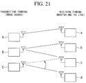
- FIG. 21 is a schematic diagram representing the configuration of a conventionally known image transmitting/receiving system.
- the image transmitting/receiving system includes transmitting terminals A, B, and C and receiving terminals a, b, c, and d.
- the transmitting terminals A, B, and C are apparatuses that transmit an image signal.
- the receiving terminals a, b, c, and d are apparatuses that receive the image signal and display an image based on the received image signal.
- a first requirement is to wirelessly transmit an image from a plurality of (n) transmitting terminals (image sources) to a plurality of (m) receiving terminals (monitors).
- a second requirement is to wirelessly transmit an image from one of the plurality of (n) transmitting terminals (image sources) to the plurality of (m) receiving terminals (monitors).
- a third requirement is to freely change a connection combination of the transmitting terminals and the receiving terminals.
- it is to change a receiving terminal, which is a destination of an image transmitted by the transmitting terminal C, from the receiving terminal d to the receiving terminal c.
- FIG. 22 is a schematic diagram representing image signal transmission timings and blanking intervals in the conventionally known image transmitting/receiving system.
- a horizontal axis denotes time.
- the transmitting terminal A and the receiving terminal a perform the transmission/reception of an image signal
- the transmitting terminal B and the receiving terminal b perform the transmission/reception of an image signal.
- the timing at which the transmitting terminal A transmits the image signal is different from the timing at which the transmitting terminal B transmits the image signal.
- the blanking intervals are different from each other.
- blanking intervals do not synchronize with one another among the transmitting terminals (when there are a plurality of combinations of transmitting terminals and receiving terminals, among the plurality of combinations). For example, as illustrated in FIG. 22 , between a combination of the transmitting terminal A and the receiving terminal a and a combination of the transmitting terminal B and the receiving terminal b, blanking intervals do not synchronize with one another.
- the transmitting terminal A transmits a control signal to the receiving terminal b
- the receiving terminal b receives the control signal in a period (an image signal transmission period) other than its own blanking interval.
- An object of the present invention is to provide an image transmitting/receiving system, an image transmitting apparatus, a received image displaying apparatus, a wireless control apparatus, and an image transmitting/receiving method, by which it is possible to perform the switching of a communication connection without influencing the transmission/reception of an image signal.
- an image transmitting/receiving system according to claim 1, an image transmitting apparatus according to claim 4, a received image displaying apparatus according to claim 13, a wireless control apparatus according to claim 24, and an image transmitting/receiving method according to claim 26.
- an image transmitting/receiving system includes a plurality of image transmitting apparatuses which continuously wirelessly transmit continuously captured frame images in a captured order and a plurality of received image displaying apparatuses which continuously wirelessly receive the frame images continuously wirelessly transmitted by the plurality of image transmitting apparatuses and continuously display the received frame images in the captured order.
- the image transmitting apparatus includes: a wireless communication unit which wirelessly transmits the frame image to the received image displaying apparatus, which has established a wireless communication connection with the image transmitting apparatus, in synchronization with a reference synchronization signal.
- the received image displaying apparatus includes: a wireless communication unit which wirelessly receives the frame images transmitted from the image transmitting apparatus having established a wireless communication connection with the received image displaying apparatus; and a display unit which displays the frame images, which have been wirelessly received in the wireless communication unit, in the captured order of the frame images.
- At least one apparatus of the image transmitting apparatus and the received image displaying apparatus included in the image transmitting/receiving system includes: a reference synchronization signal generation unit which generates a reference synchronization signal; and a control unit which controls the reference synchronization signal generation unit to generate the reference synchronization signal and controls the wireless communication unit to wirelessly transmit the reference synchronization signal to another apparatus included in the image transmitting/receiving system when the wireless communication unit does not receive the reference synchronization signal within a constant period.
- At least one of the image transmitting apparatus and the received image displaying apparatus includes: a blanking interval recognition unit which recognizes a vertical blanking interval of the frame image; and a disconnection control unit which controls the wireless communication unit to start a disconnection process of wireless communication within a period of the vertical blanking interval recognized by the blanking interval recognition unit.
- the disconnection control unit provided in the at least one of the image transmitting apparatus and the received image displaying apparatus controls the wireless communication unit not to perform the disconnection process outside of the vertical blanking interval.
- the blanking interval recognition unit recognizes the vertical blanking interval based on the frame image or the reference synchronization signal.
- the present invention provides an image transmitting apparatus in an image transmitting/receiving system, which includes a plurality of image transmitting apparatuses which continuously wirelessly transmit continuously captured frame images in a captured order and a plurality of received image displaying apparatuses which continuously wirelessly receive the frame images continuously wirelessly transmitted by the plurality of image transmitting apparatuses and continuously display the received frame images in the captured order
- the image transmitting apparatus includes: a wireless communication unit which wirelessly transmits the frame image to the received image displaying apparatus, which has established a wireless communication connection with the image transmitting apparatus, in synchronization with a reference synchronization signal; a reference synchronization signal generation unit which generates a reference synchronization signal; a control unit which controls the reference synchronization signal generation unit to generate the reference synchronization signal and controls the wireless communication unit to wirelessly transmit the reference synchronization signal to another apparatus included in the image transmitting/receiving system when the wireless communication unit does not receive the reference synchronization signal within a constant period; a blanking interval recognition
- control unit controls the wireless communication unit to transmit the reference synchronization signal within the vertical blanking interval.
- the image transmitting apparatus of the present invention further includes a detection unit which detects a plurality of communication channels used when another image transmitting apparatus included in the image transmitting/receiving system wirelessly transmits the frame image, wherein the control unit controls the wireless communication unit to transmit the reference synchronization signal through each communication channel detected by the detection unit.
- the control unit controls the wireless communication unit to transmit the reference synchronization signal through only some of the plurality of communication channels detected by the detection unit, in a single vertical blanking interval.
- control unit controls the wireless communication unit to transmit the reference synchronization signal through one of the plurality of communication channels detected by the detection unit, in the single vertical blanking interval.
- the image transmitting apparatus of the present invention further includes an instruction receiving unit which receives an instruction for addition, modification, and deletion of a transmission destination of the frame image, and, when the instruction receiving unit receives the instruction, the disconnection control unit controls the wireless communication unit to start the disconnection process.
- an instruction receiving unit which receives an instruction for addition, modification, and deletion of a transmission destination of the frame image, and, when the instruction receiving unit receives the instruction, the disconnection control unit controls the wireless communication unit to start the disconnection process.
- the image transmitting apparatus of the present invention further includes an operation unit which receives an operation by a user, and the instruction receiving unit receives the instruction based on the operation received in the operation unit.
- the instruction receiving unit receives the instruction from another apparatus included in the image transmitting/receiving system through the communication unit.
- the disconnection control unit controls the wireless communication unit not to perform the disconnection process outside of the vertical blanking interval.
- the present invention provides a received image displaying apparatus in an image transmitting/receiving system, which includes a plurality of image transmitting apparatuses which continuously wirelessly transmit continuously captured frame images in a captured order and a plurality of received image displaying apparatuses which continuously wirelessly receive the frame images continuously wirelessly transmitted by the plurality of image transmitting apparatuses and continuously display the received frame images in the captured order
- the received image displaying apparatus includes: a wireless communication unit which wirelessly receives the frame images from the image transmitting apparatus having established a wireless communication connection with the received image displaying apparatus; a display unit which displays the frame images wirelessly received in the wireless communication unit, in a captured order of the frame images; a reference synchronization signal generation unit which generates a reference synchronization signal; a control unit which controls the reference synchronization signal generation unit to generate the reference synchronization signal and controls the wireless communication unit to wirelessly transmit the reference synchronization signal to another apparatus included in the image transmitting/receiving system when the wireless communication unit does not receive the reference
- the wireless communication unit wirelessly receives the frame images in a form of packet data
- the reference synchronization signal generation unit generates the reference synchronization signal based on packet data, which indicates final data of each frame of the frame images, among the packet data wirelessly received in the wireless communication unit.
- the control unit controls the wireless communication unit to wirelessly transmit the reference synchronization signal generated by the reference synchronization signal generation unit, according to packet data indicating a response for packet data, which indicates final data of each frame of the frame images, among the packet data wirelessly received in the wireless communication unit.
- the wireless communication unit wirelessly receives the frame images in a form of packet data
- the blanking interval recognition unit recognizes the vertical blanking interval of the frame image based on whether the packet data wirelessly received in the wireless communication unit is packet data indicating final data of each frame of the frame images.
- the received image displaying apparatus of the present invention further includes a detection unit which detects a plurality of communication channels used when another image transmitting apparatus included in the image transmitting/receiving system wirelessly transmits the frame image, and the control unit controls the wireless communication unit to transmit the reference synchronization signal through each communication channel detected by the detection unit.
- the control unit controls the wireless communication unit to transmit the reference synchronization signal through only some of the plurality of communication channels detected by the detection unit, in a single vertical blanking interval.
- control unit controls the wireless communication unit to transmit the reference synchronization signal through one of the plurality of communication channels detected by the detection unit, in the single vertical blanking interval.
- the received image displaying apparatus of the present invention further includes an instruction receiving unit which receives an instruction for addition, modification, and deletion of a transmission destination of the frame image, and, when the instruction receiving unit receives the instruction, the disconnection control unit controls the wireless communication unit to start the disconnection process.
- an instruction receiving unit which receives an instruction for addition, modification, and deletion of a transmission destination of the frame image, and, when the instruction receiving unit receives the instruction, the disconnection control unit controls the wireless communication unit to start the disconnection process.
- the received image displaying apparatus of the present invention further includes an operation unit which receives an operation by a user, and the instruction receiving unit receives the instruction based on the operation received in the operation unit.
- the instruction receiving unit receives the instruction from another apparatus included in the image transmitting/receiving system through the communication unit.
- the disconnection control unit controls the wireless communication unit not to perform the disconnection process outside of the vertical blanking interval.
- the present invention provides a wireless control apparatus in an image transmitting/receiving system, which includes a plurality of image transmitting apparatuses which continuously wirelessly transmit continuously captured frame images in a captured order, a plurality of received image displaying apparatuses which continuously wirelessly receive the frame images continuously wirelessly transmitted by the plurality of image transmitting apparatuses and continuously display the received frame images in the captured order, and the wireless control apparatus which instructs the image transmitting apparatus to wirelessly communicate with the received image displaying apparatus serving as a transmission destination of the frame image and instructs the received image displaying apparatus to wirelessly communicate with the image transmitting apparatus serving as a transmission source of the frame image
- the wireless control apparatus includes: a wireless communication unit which wirelessly communicates with the image transmitting apparatus and the received image displaying apparatus; a reference synchronization signal generation unit which generates a reference synchronization signal; and a control unit which controls the reference synchronization signal generation unit to generate the reference synchronization signal and controls the wireless communication unit to wirelessly transmit the reference synchronization signal to another
- the wireless control apparatus of the present invention includes: an instruction receiving unit which receives an instruction for addition, modification, and deletion of a combination of the apparatus serving as the transmission destination of the frame image and the apparatus serving as the transmission source of the frame image; and a disconnection instruction control unit which controls the wireless communication unit to transmit an instruction for starting a disconnection process of wireless communication to the apparatus of the combination received in the instruction receiving unit when the instruction receiving unit receives the instruction.
- the present invention provides an image transmitting/receiving method in an image transmitting/receiving system, which includes a plurality of image transmitting apparatuses which continuously wirelessly transmit continuously captured frame images in a captured order and a plurality of received image displaying apparatuses which continuously wirelessly receive the frame images continuously wirelessly transmitted by the plurality of image transmitting apparatuses and continuously display the received frame images in the captured order
- the image transmitting/receiving method includes: a wireless transmission step of wirelessly transmitting, by a wireless communication unit of the image transmitting apparatus, the frame image to the received image displaying apparatus, which has established a wireless communication connection with the image transmitting apparatus, in synchronization with a reference synchronization signal; a wireless reception step of wirelessly receiving, by a wireless communication unit of the received image displaying apparatus, the frame image transmitted from the image transmitting apparatus having established a wireless communication connection with the received image displaying apparatus; a display step of displaying, by a display unit of the received image displaying apparatus, the frame images, which
- At least one of the image transmitting apparatus and the received image displaying apparatus included in the image transmitting/receiving system includes a reference synchronization signal generation unit which generates a reference synchronization signal, and a control unit which controls the reference synchronization signal generation unit to generate the reference synchronization signal and controls the wireless communication unit to wirelessly transmit the reference synchronization signal to another apparatus included in the image transmitting/receiving system when the wireless communication unit does not receive the reference synchronization signal within a constant period.
- At least one of the image transmitting apparatus and the received image displaying apparatus includes a blanking interval recognition unit which recognizes a vertical blanking interval of the frame image, and a disconnection control unit which controls the wireless communication unit to start a disconnection process of wireless communication within a period of the vertical blanking interval recognized by the blanking interval recognition unit.
- the image transmitting/receiving system of the present invention it is possible to start the disconnection process of wireless communication within the period of the vertical blanking interval, so that it is possible to perform the switching of a communication connection without influencing the transmission/reception of an image signal.
- the image transmitting apparatus of the present invention includes a wireless communication unit which wirelessly transmits the frame image to the received image displaying apparatus, which has established a wireless communication connection with the image transmitting apparatus, in synchronization with a reference synchronization signal, a reference synchronization signal generation unit which generates a reference synchronization signal, a control unit which controls the reference synchronization signal generation unit to generate the reference synchronization signal and controls the wireless communication unit to wirelessly transmit the reference synchronization signal to another apparatus included in the image transmitting/receiving system when the wireless communication unit does not receive the reference synchronization signal within a constant period, a blanking interval recognition unit which recognizes a vertical blanking interval of the frame image, and a disconnection control unit which controls the wireless communication unit to start a disconnection process of wireless communication within a period of the vertical blanking interval recognized by the blanking interval recognition unit.
- the image transmitting apparatus of the present invention it is possible to start the disconnection process of wireless communication within the period of the vertical blanking interval, so that it is possible to perform the switching of a communication connection without influencing the transmission/reception of an image signal.
- the received image displaying apparatus of the present invention includes a wireless communication unit which wirelessly receives the frame images from the image transmitting apparatus having established a wireless communication connection with the received image displaying apparatus, a display unit which displays the frame images wirelessly received in the wireless communication unit, in a captured order of the frame images, a reference synchronization signal generation unit which generates a reference synchronization signal, a control unit which controls the reference synchronization signal generation unit to generate the reference synchronization signal and controls the wireless communication unit to wirelessly transmit the reference synchronization signal to another apparatus included in the image transmitting/receiving system when the wireless communication unit does not receive the reference synchronization signal within a constant period, a blanking interval recognition unit which recognizes a vertical blanking interval of the frame image, and a disconnection control unit which controls the wireless communication unit to start a disconnection process of wireless communication within a period of the vertical blanking interval recognized by the blanking interval recognition unit.
- the received image displaying apparatus of the present invention it is possible to start the disconnection process of wireless communication within the period of the vertical blanking interval, so that it is possible to perform the switching of a communication connection without influencing the transmission/reception of an image signal.
- the wireless apparatus of the present invention includes a wireless communication unit which wirelessly communicates with the image transmitting apparatus and the received image displaying apparatus, a reference synchronization signal generation unit which generates a reference synchronization signal, and a control unit which controls the reference synchronization signal generation unit to generate the reference synchronization signal and controls the wireless communication unit to wirelessly transmit the reference synchronization signal to another apparatus included in the image transmitting/receiving system when the wireless communication unit does not receive the reference synchronization signal within a constant period.
- the wireless apparatus of the present invention it is possible to wirelessly transmit the reference synchronization signal to another apparatus and for the other apparatus having received the reference synchronization signal to start the disconnection process of wireless communication based on the reference synchronization signal, so that it is possible to perform the switching of a communication connection without influencing the transmission/reception of an image signal.
- the image transmitting/receiving method of the present invention includes a wireless transmission step of wirelessly transmitting, by a wireless communication unit of the image transmitting apparatus, the frame image to the received image displaying apparatus, which has established a wireless communication connection with the image transmitting apparatus, in synchronization with a reference synchronization signal, a wireless reception step of wirelessly receiving, by a wireless communication unit of the received image displaying apparatus, the frame image transmitted from the image transmitting apparatus having established a wireless communication connection with the received image displaying apparatus, a display step of displaying, by a display unit of the received image displaying apparatus, the frame images, which have been wirelessly received in the wireless communication unit, in the captured order of the frame images, a reference synchronization signal generation step of generating, by a reference synchronization signal generation unit of at least one of the image transmitting apparatus and the received image displaying apparatus included in the image transmitting/receiving system, a reference synchronization signal, a control step of controlling, by a control unit of at least one of the image
- the image transmitting/receiving method of the present invention it is possible to start the disconnection process of wireless communication within the vertical blanking interval, so that it is possible to perform the switching of a communication connection without influencing the transmission/reception of an image signal.
- one of image transmitting apparatuses included in an image transmitting/receiving system transmits a reference synchronization signal indicating a transmission timing of an image signal (a frame image) to other image transmitting apparatuses. Then, all image transmitting apparatuses included in the image transmitting/receiving system transmit an image signal based on the reference synchronization signal. In this way, all the image transmitting apparatuses included in the image transmitting/receiving system are able to synchronize a timing at which the image signal is transmitted with a timing (a blanking interval, a vertical blanking interval) at which no image signal is transmitted.
- the image transmitting apparatuses and received image displaying apparatuses included in the image transmitting/receiving system perform the transmission/reception of data required in order to switch the connection destination apparatus during the blanking interval. Consequently, it is possible to perform the switching of a communication connection without influencing the transmission/reception of the image signal.
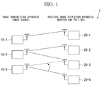
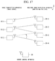
- FIG. 1 is a schematic diagram representing the configuration of an image transmitting/receiving system in the present preferred embodiment.
- an image transmitting/receiving system 1 includes image transmitting apparatuses 10-1 to 10-3 and received image displaying apparatuses 20-1 to 20-4.
- the image transmitting apparatuses 10-1 to 10-3 are apparatuses that continuously wirelessly transmit continuously captured image signals in a captured order.
- the received image displaying apparatuses 20-1 to 20-4 are apparatuses that continuously receive the image signals and continuously display the received image signals in the captured order.
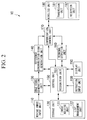
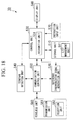
- FIG. 2 is a block diagram representing the configuration of the image transmitting apparatus 10 in the present preferred embodiment.
- the image transmitting apparatus 10 includes a moving image input unit 110, a storage unit 120, an image signal generation unit 130, a reference synchronization signal generation unit 140, a control unit 150, a terminal detection unit 160, a communication control unit 170 (a disconnection control unit), a wireless unit 180 (a wireless communication unit), an instruction input unit 190 (an operation unit), and a display unit 200.
- the moving image input unit 110 receives moving image data to be transmitted.
- An example of the moving image input unit 110 includes an imaging device including an imaging element such as a CCD (Charged Coupled Device), a moving image recording device such as an HDD (Hard Disk Drive) or DVD (Digital Versatile Disc), and a moving image input means represented by DVI (Digital Visual Interface), HDMI (registered trademark) (High-Definition Multimedia Interface) and the like.
- the storage unit 120 includes an image holding unit 121 and a list management unit 122.
- the image holding unit 121 stores the moving image data input to the moving image input unit 110.
- the list management unit 122 stores a pairing list indicating combinations of the image transmitting apparatuses 10 and the received image displaying apparatuses 20, which perform communication.
- the image signal generation unit 130 generates an image signal by converting the moving image data into a format in which a moving image of one frame is generated for each constant time, which is represented by NTSC (National Television System committee), PAL (Phase Alternating Line), or BT656.
- the reference synchronization signal generation unit 140 generates a reference synchronization signal indicating a transmission timing of an image signal in all the image transmitting apparatuses 10 included in the image transmitting/receiving system 1.
- the control unit 150 performs the control of each element provided in the image transmitting apparatuses 10. Furthermore, the control unit 150 includes a recognition unit 151 (a blanking interval recognition unit) that recognizes a timing at which an image signal is transmitted, and a blanking interval, which indicates a timing at which control data is transmitted, based on the reference synchronization signal.
- the terminal detection unit 160 searches for another apparatus included in the image transmitting/receiving system 1.
- the communication control unit 170 performs the communication control (a baseband process) of an image signal (an image signal packet) or control data (a control packet).
- the wireless unit 180 includes a transmission unit 181 and a reception unit 182.
- the transmission unit 181 wirelessly transmits data, such as an image signal or control data, to another apparatus through an antenna (not illustrated).
- the reception unit 182 wirelessly receives data, which is wirelessly transmitted from another apparatus, through an antenna (not illustrated).
- the instruction input unit 190 includes a keyboard, a switch and the like, and receives instruction input from a user.
- the display unit 200 includes a liquid crystal display and the like, and displays various types of information.
- the wireless unit 180 used in the transmission/reception of an image signal is shared.
- a wireless unit dedicated for the terminal detection unit 160 may be provided.
- FIG. 3 is a block diagram representing the configuration of the received image displaying apparatus 20 in the present preferred embodiment.
- the received image displaying apparatus 20 includes a wireless unit 300 (a wireless communication unit), a communication control unit 310 (a disconnection control unit), a control unit 320, a reference synchronization signal generation unit 330, a terminal detection unit 340, a storage unit 350, an instruction input unit 360, and a display unit 370.
- the wireless unit 300 includes a transmission unit 301 and a reception unit 302.
- the transmission unit 301 wirelessly transmits data to another apparatus through an antenna (not illustrated).
- the reception unit 302 wirelessly receives data, which is wirelessly transmitted from another apparatus, through an antenna (not illustrated).
- the communication control unit 310 performs the communication control (a baseband process) of an image signal (an image signal packet) or control data (a control packet).
- the control unit 320 performs the control of each element provided in the received image displaying apparatus 20.
- the control unit 320 includes a recognition unit 321 (a blanking interval recognition unit).
- the recognition unit 321 recognizes a blanking interval indicating a timing at which the control data is transmitted, and further recognizes a final packet in each frame of the image signal received in the reception unit 302.
- the transmission unit 302 has functions of transmitting an ACK signal for the final packet, and transmitting a reference synchronization signal generated by the reference synchronization signal generation unit 330 after transmitting the ACK signal.
- the reference synchronization signal generation unit 330 generates a reference synchronization signal indicating a transmission timing of an image signal in all the image transmitting apparatuses 10 included in the image transmitting/receiving system 1.
- the terminal detection unit 340 searches for another apparatus included in the image transmitting/receiving system 1.
- the storage unit 350 stores data used in the received image displaying apparatus 20.
- the instruction input unit 360 includes a keyboard, a switch and the like, and receives instruction input from a user.
- the display unit 370 includes a liquid crystal display and the like, and displays an image (a moving image) based on an image signal.
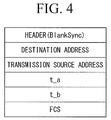
- FIG. 4 is a schematic diagram representing the data structure of the reference synchronization signal in the present preferred embodiment.
- the reference synchronization signal has data items of a header BlankSync, a destination address, a transmission source address, t_a, t_b, and an FCS (Frame Check Sequence).
- the header stores data indicating the reference synchronization signal, and the like.
- As the destination address an address of an apparatus to which the reference synchronization signal is transmitted is stored.
- the destination may be a broadcast address or a multicast address for a specific group.
- As the transmission source address an address of a transmission source apparatus of the reference synchronization signal is stored.
- t_a a period t_a indicating a predetermined period from a start time point of a blanking interval is stored.
- t_b a period t_b indicating a predetermined period from a time point at which the reference synchronization signal has been transmitted is stored.
- the FCS stores data for error detection and error correction of the reference synchronization signal.
- FIG. 5 is a schematic diagram representing timings at which the image transmitting apparatus 10 transmits the reference synchronization signal in the present preferred embodiment.
- a horizontal axis denotes time.
- the image transmitting apparatus 10 transmits the reference synchronization signal at a time point at which the predetermined period t_a has passed from a time point at which a blanking period has started. Furthermore, the image transmitting apparatus 10 waits for a process until the predetermined period t_b passes from the time point at which the reference synchronization signal has been transmitted, and then transmits an image signal of one frame.
- the timing at which the image transmitting apparatus 10 transmits the reference synchronization signal for example, may be positioned immediately after the blanking period has started, or may be within the blanking period. However, the timing at which the image transmitting apparatus 10 transmits the reference synchronization signal is assumed to be a constant timing each time.
- the reference synchronization signal generation unit 140 stores, in the reference synchronization signal, information on one or both of the period t_a indicating the predetermined period from the time point at which the blanking interval has started and the period t_b indicating the predetermined period from the time point at which the reference synchronization signal has been transmitted. Consequently, an apparatus having received the reference synchronization signal is able to recognize the timing at which the blanking interval starts and the timing at which the blanking interval ends.
- the pairing list may be managed and stored in a unified manner by any apparatus included in the image transmitting/receiving system 1, or managed and stored by each apparatus.
- all pairing lists need to have the same information.
- FIG. 6 is a schematic diagram representing an example of the pairing list in the present preferred embodiment.
- the pairing list has data items of "ID,” “Tx ID,” “CH ID,” “Rx ID,” and “Sync,” and stores data of each data item by associating the data in each row.
- the data item "ID” stores a number for uniquely specifying a set of data stored in the pairing list.
- the data item “Tx ID” stores a number for uniquely specifying an image transmitting apparatus 10.
- the data item “CH ID” stores a number for uniquely specifying a channel used in wireless communication between an image transmitting apparatus 10 uniquely specified by “Tx ID” stored in the same row and a received image displaying apparatus 20 uniquely specified by “Rx ID” stored in the same row.
- the data item “Rx ID” stores a number for uniquely specifying a received image displaying apparatus 20.
- the data item "Sync” stores information indicating a communication state between the image transmitting apparatus 10 uniquely specified by the “Tx ID” stored in the same row and the received image displaying apparatus 20 uniquely specified by the “Rx ID” stored in the same row.
- the "Sync” is “OK,” it indicates that synchronous transmission is being performed.
- the "Sync” is "None,” it indicates a non-connection.
- the "Sync” is "During,” it indicates that synchronization is being set (a connection is currently not possible).
- a value stored in the data item "ID” of a row 601 is “001”
- a value stored in the data item “Tx ID” is “0001,”
- a value stored in the data item “CH ID” is “001”
- a value stored in the data item “Rx ID” is “0001,”
- a value stored in the data item “Sync” is “OK.”
- a set of data specified by the ID "001” indicates that an image transmitting apparatus 10 uniquely specified by the Tx ID "0001” and a received image displaying apparatus 20 uniquely specified by the Rx ID "0001” are connected to each other for communication using a channel specified by the CH ID "001,” and indicates that synchronous transmission is being performed because the Sync is "OK.”
- Other rows are as illustrated in FIG. 6 .
- FIG. 7 illustrates an example of a pairing list when a communication destination of a received image displaying apparatus 20 uniquely specified by the Tx ID "0003" and a received image displaying apparatus 20 uniquely specified by the Tx ID "0004" has changed in the state of the pairing list illustrated in FIG. 6 .
- sets of data uniquely specified by the IDs "003" to "005" are different from the example illustrated in FIG. 6 .
- the pairing list is also updated.
- the content indicated by each row is as illustrated in FIG. 7 .
- the image transmitting apparatuses 10-2 and 10-3 update pairing lists stored therein. Then, the image transmitting apparatus 10-3, which transmits no reference synchronization signal, transmits update content of the pairing list to the image transmitting apparatus 10-2.
- the image transmitting apparatus 10-2 having received the update content updates the pairing list stored therein based on the received content, and transmits an updated pairing list to all the image transmitting apparatuses 10 included in the image transmitting/receiving system 1.
- the image transmitting apparatus 10-2 managing the consistency of the pairing list is notified of updated content when a communication connection environment of another image transmitting apparatus 10 (or another received image displaying apparatus 20) has been updated as well as when a communication connection environment of the image transmitting apparatus 10-2 has been updated, the image transmitting apparatus 10-2 is able to update the pairing list stored therein. Furthermore, after updating the pairing list, the image transmitting apparatus 10-2 transmits the updated pairing list to all the image transmitting apparatuses 10 included in the image transmitting/receiving system 1. In this way, it is possible to maintain the consistency of the pairing lists stored in the image transmitting apparatuses 10 included in the image transmitting/receiving system 1. In addition, since the update process of the pairing list is performed within the blanking interval (in addition, it may not be a blanking interval when the connection environment has been updated), it is possible to perform the process without influencing the transmission/reception of an image signal.
- the pairing list may be broadcast or multicast to each channel at a predetermined timing during the blanking interval.
- the image transmitting apparatuses 10 and the received image displaying apparatuses 20 included in the image transmitting/receiving system 1 are able to receive the pairing list.
- the predetermined timing is arbitrary.
- the pairing list is transmitted at a timing of once per second (once every 60 frames in the case of a moving image of 60 frames).
- the pairing list may also be transmitted in a multicast manner.
- Each apparatus included in the image transmitting/receiving system 1 is able to share the pairing list, and an image transmitting apparatus 10 and a received image displaying apparatus 20, which newly perform a connection operation, are able to select a device with which the blanking interval synchronizes. In this way, it is possible to transmit/receive a control signal out of the transmission/reception timings of a moving image, so that it is possible to prevent a collision with the transmission/reception of the moving image.
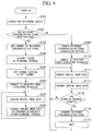
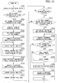
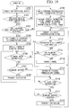
- FIG. 8 is a flowchart illustrating the operation procedure of the image transmitting apparatus 10 in the present preferred embodiment.
- Step S101 The terminal detection unit 160 searches for another apparatus included in the image transmitting/receiving system 1. Then, the procedure proceeds to a process of step S102.
- Step S102 The recognition unit 151 determines whether a reference synchronization signal transmitted from another apparatus has been received in the reception unit 182 during a constant period. When the recognition unit 151 determines that the reference synchronization signal transmitted from another apparatus has been received in the reception unit 182, the procedure proceeds to a process of step S103. Otherwise, the procedure proceeds to a process of step S109.
- Step S103 The communication control unit 170 matches a reception channel of the reception unit 182 with a channel through which the reference synchronization signal has been transmitted in order to receive the reference synchronization signal. Then, the procedure proceeds to a process of step S104.
- Step S104 The reception unit 182 receives the reference synchronization signal transmitted from another image transmitting apparatus 10. Furthermore, the recognition unit 151 recognizes a timing at which an image signal is transmitted, and a timing of a blanking interval based on the reference synchronization signal received in the reception unit 182. Then, the procedure proceeds to a process of step S105.
- Step S105 The communication control unit 170 changes a channel through which the transmission unit 181 transmits an image signal (an image signal packet) to a free channel. Then, the procedure proceeds to a process of step S106.
- Step S106 The transmission unit 181 performs a communication connection with the received image displaying apparatus 20, which is a communication partner determined in advance, using the channel set in the process of step S105. Then, the procedure proceeds to a process of step S107.
- Step S107 The image signal generation unit 130 generates an image signal of one frame using the moving image data stored in the image holding unit 121. Then, the procedure proceeds to a process of step S108.
- Step S108 The communication control unit 170 allows the image signal of one frame generated by the image signal generation unit 130 in the process of step S107 to synchronize with the timing at which the image signal is transmitted, which has been recognized by the recognition unit 151 in the process of step S104, and transmits the image signal to the received image displaying apparatus 20 having performed the communication connection in the process of step S106. Then, the procedure returns to the process of step S107. In addition, the image signal generation unit 130 and the communication control unit 170 repeat the processes of step S107 and step S108 until the transmission of the image signal is stopped, such as the reception of a transmission stop instruction by the instruction input unit 190.
- Step S109 When the reference synchronization signal has not been received in step S102, the control unit 150 controls the reference synchronization signal generation unit 140 to generate the reference synchronization signal.
- the reference synchronization signal generation unit 140 generates the reference synchronization signal.
- the reference synchronization signal generation unit 140 continuously generates the reference synchronization signal until the image transmitting apparatus 10 is powered off. Then, the procedure proceeds to a process of step S110.
- Step S110 The transmission unit 181 performs a communication connection with the received image displaying apparatus 20, which is a communication partner determined in advance, using a currently set channel. Then, the procedure proceeds to a process of step S111.
- Step S111 The image signal generation unit 130 generates the image signal of one frame using the moving image data stored in the image holding unit 121. Then, the procedure proceeds to a process of step S 112.
- Step S112 The communication control unit 170 controls the transmission unit 181 to transmit the image signal of one frame generated by the image signal generation unit 130 in the process of step S111 to the received image displaying apparatus 20 having performed the communication connection in the process of step S110. Then, the procedure proceeds to a process of step S113.
- Step S113 The recognition unit 151 recognizes whether a current time point is a blanking interval based on the reference synchronization signal generated by the reference synchronization signal generation unit 140 in the process of step S109. When the recognition unit 151 recognizes that the current time point is the blanking interval, the procedure proceeds to a process of step S114. Otherwise, the procedure returns to the process of step S111.
- Step S114 Since the current time point is the blanking interval, the communication control unit 170 controls the transmission unit 181 to transmit the reference synchronization signal generated by the reference synchronization signal generation unit 140 to other image transmitting apparatuses 10 included in the image transmitting/receiving system 1 in the form of a packet. Then, the procedure proceeds to a process of step S 115.
- Step S115 The communication control unit 170 temporarily stops (waits for) a transmission process until the blanking interval ends. After the blanking interval ends, the procedure returns to the process of step S111.
- step S101 to step S115 when another apparatus transmits no reference synchronization signal, the image transmitting apparatus 10 is able to generate the reference synchronization signal and transmit the generated reference synchronization signal to other apparatuses in the blanking interval. Furthermore, based on the reference synchronization signal, the other apparatuses having received the reference synchronization signal are able to recognize the image signal transmission timing and the blanking interval.
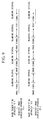
- FIG. 9 is a schematic diagram representing image signal transmission timings and blanking intervals in the present preferred embodiment.
- a horizontal axis denotes time.
- the image transmitting apparatus 10-1 and the received image displaying apparatus 20-1 perform the transmission/reception of an image signal
- the image transmitting apparatus 10-2 and the received image displaying apparatus 20-2 perform the transmission/reception of an image signal. Since the image transmitting apparatus 10-1 and the image transmitting apparatus 10-2 transmit the image signal based on the reference synchronization signal, the timing at which the image transmitting apparatus 10-1 transmits the image signal coincides with the timing at which the image transmitting apparatus 10-2 transmits the image signal. Furthermore, the blanking intervals in the image transmitting apparatus 10-1 and the image transmitting apparatus 10-2 coincide with each other. In addition, all the apparatuses included in the image transmitting/receiving system 1 perform the transmission/reception of the image signal at the illustrated timings at which the image signal is transmitted and at the illustrated timings at which the blanking intervals coincide with each other.
- FIG. 10 is a sequence diagram representing an operation procedure when switching a connection between the image transmitting apparatus 10 and the received image displaying apparatus 20 in the present preferred embodiment.
- a vertical axis indicates the passage of time.
- FIG. 10 illustrates an example of the case in which, when the image transmitting apparatus 10-2 transmits an image signal to the received image displaying apparatuses 20-2 and 20-3 using a communication channel CH2, and the image transmitting apparatus 10-3 transmits an image signal to the received image displaying apparatus 20-4 using a communication channel CH3, a destination to which the image transmitting apparatus 10-3 transmits the image signal is switched to the received image displaying apparatus 20-3.
- Step S201 The image transmitting apparatus 10-2 transmits an image signal to the received image displaying apparatuses 20-2 and 20-3, and the image transmitting apparatus 10-3 transmits an image signal to the received image displaying apparatus 20-4.
- the image transmitting apparatus 10-2 and the image transmitting apparatus 10-3 transmit the image signals according to the image signal transmission timing based on the reference signal as described above.
- the timing at which the image transmitting apparatus 10-2 transmits the image signal to the received image displaying apparatuses 20-2 and 20-3 is different from the timing at which the image transmitting apparatus 10-3 transmits the image signal to the received image displaying apparatus 20-4.
- this is for illustrative purposes only, and the image transmitting apparatus 10-2 and the image transmitting apparatus 10-3 actually transmit the image signals at the same timing.
- Step S202 The instruction input unit 190 of the image transmitting apparatus 10-3 receives the input of an instruction for switching a transmission destination of the image signal from the received image displaying apparatus 20-4 to the received image displaying apparatus 20-3.
- Step S203 The image transmitting apparatus 10-3 switches a communication channel from the CH3 to the CH2.
- Step S204 After a blanking interval starts, the image transmitting apparatus 10-3 transmits a switching request message for asking for permission to start communication with the received image displaying apparatus 20-4 to the image transmitting apparatus 10-2.
- Step S205 When the switching request message is received in the process of step S203, the image transmitting apparatus 10-2 determines whether to permit the communication with the received image displaying apparatus 20-4, and transmits a switching permission message to the image transmitting apparatus 10-3 when it is determined to permit the communication.
- Step S206 The image transmitting apparatuses 10-2 and 10-3 determine whether it is possible to switch a communication connection within the blanking interval. When it is determined that it is possible to switch the communication connection within the blanking interval, the image transmitting apparatuses 10-2 and 10-3 perform processes after step S206. When it is determined that it is not possible to switch the communication connection within the blanking interval, the image transmitting apparatuses 10-2 and 10-3 return the CH to the original channel, stop a switching process of the communication connection in this blanking interval, and perform the processes after step S206 in the next blanking interval.
- Step S207 The image transmitting apparatus 10-3 transmits a connection request message to the received image displaying apparatus 20-3.
- Step S208 The received image displaying apparatus 20-3 transmits a disconnection request message to the image transmitting apparatus 10-2.
- Step S209 The image transmitting apparatus 10-2 transmits a disconnection message to the received image displaying apparatus 20-3, and then disconnects a communication connection with the received image displaying apparatus 20-3.
- Step S210 The received image displaying apparatus 20-3 disconnects a communication connection with the image transmitting apparatus 10-2, and then transmits a disconnection completion message to the image transmitting apparatus 10-3.
- Step S211 The image transmitting apparatus 10-3 and the received image displaying apparatus 20-3 switch a communication channel from the CH2 to the CH3.
- Step S212 The image transmitting apparatus 10-3 transmits a disconnection request message to the received image displaying apparatus 20-4.
- Step S213 The received image displaying apparatus 20-4 transmits a disconnection completion message and information specifying a channel (a free channel) to be used later by the received image displaying apparatus 20-4 to the image transmitting apparatus 10-3, and then disconnects a communication connection with the image transmitting apparatus 10-3. Then, the received image displaying apparatus 20-4 changes a communication channel to the free channel, and waits for a connection.
- Step S214 The image transmitting apparatus 10-2 deletes the received image displaying apparatus 20-3 from the pairing list stored therein, and updates the pairing list.
- Step S215) The image transmitting apparatus 10-2 deletes a combination with the received image displaying apparatus 20-4 from the pairing list stored therein, and updates a communication channel, which is stored in the pairing list and used by the received image displaying apparatus 20-4, based on the information received in the process of step S213 and specifying the channel to be used later by the received image displaying apparatus 20-4.
- Step S216 The image transmitting apparatus 10-3 switches a communication channel from the CH3 to the CH2.
- Step S21-7 The image transmitting apparatus 10-3 transmits the pairing list updated in the process of step S215 to the image transmitting apparatus 10-2.
- Step S228 The image transmitting apparatus 10-2 updates the pairing list stored therein based on the pairing list received in the process of step S217.
- Step S219) The image transmitting apparatus 10-2 transmits the pairing list updated in the process of step S218 to the image transmitting apparatus 10-3.
- the image transmitting apparatus 10-3 updates the pairing list stored therein based on the received pairing list.
- Step S220 The image transmitting apparatus 10-3 switches a communication channel from the CH2 to the CH3.
- Step S221) The image transmitting apparatus 10-3 starts a communication connection with the received image displaying apparatus 20-3, and then transmits a connection message to the received image displaying apparatus 20-3.
- Step S222 The received image displaying apparatus 20-3 starts a communication connection with the image transmitting apparatus 10-3, and then transmits a connection completion message to the image transmitting apparatus 10-3.
- Step S223 The image transmitting apparatus 10-2 and the image transmitting apparatus 10-3 perform update processes (which are the same as the processes of step S214 to step S220) of the pairing lists.
- Step S224 After the blanking interval ends, the image transmitting apparatus 10-2 transmits the image signal to the received image displaying apparatus 20-2, and the image transmitting apparatus 10-3 transmits the image signal to the received image displaying apparatus 20-3.
- the timing at which the image transmitting apparatus 10-2 transmits the image signal to the received image displaying apparatus 20-2 is different from the timing at which the image transmitting apparatus 10-3 transmits the image signal to the received image displaying apparatus 20-3.
- this is for illustrative purposes only, and the image transmitting apparatus 10-2 and the image transmitting apparatus 10-3 actually transmit the image signals at the same timing.
- the list update processes (the processes of step S214 to step S220 and the process of step S223) are performed in the blanking interval when the communication switching process has been performed.
- the present invention is not limited thereto.
- the list update processes may be performed in the blanking interval after that in which the communication switching process has been performed.
- step S201 to step S224 when switching a connection destination apparatus, the image transmitting apparatuses 10 and the received image displaying apparatuses 20 included in the image transmitting/receiving system 1 perform the transmission/reception of data required in order to switch the connection destination apparatus during the blanking interval. Consequently, it is possible to perform the switching of a communication connection without influencing the transmission/reception of an image signal.
- one of the image transmitting apparatuses 10 included in the image transmitting/receiving system 1 transmits the reference synchronization signal indicating the transmission timing of the image signal to the other image transmitting apparatuses 10. Then, all the image transmitting apparatuses 10 included in the image transmitting/receiving system 1 transmit the image signal based on the reference synchronization signal. In this way, all the image transmitting apparatuses 10 included in the image transmitting/receiving system 1 are able to allow the timing at which the image signal is transmitted to synchronize with the timing (the blanking interval) at which the image signal is not transmitted.
- the image transmitting apparatuses 10 and the received image displaying apparatuses 20 included in the image transmitting/receiving system 1 perform the transmission/reception of data required in order to switch the connection destination apparatus during the blanking interval. Consequently, it is possible to perform the switching of a communication connection without influencing the transmission/reception of an image signal.
- an image transmitting/receiving system 1 an image transmitting apparatus 10, and a received image displaying apparatus 20 have the same configurations as those of the image transmitting/receiving system 1, the image transmitting apparatus 10, and the received image displaying apparatus 20 of the first preferred embodiment.
- FIG. 11 is a flowchart illustrating the operation procedure of the image transmitting apparatus 10 in the present preferred embodiment.
- Processes of step S301 to step S313 are the same as the processes of step S101 to step S113 in the first preferred embodiment.
- Step S314 The control unit 150 determines whether there is a channel through which the reference synchronization signal is not transmitted. When the control unit 150 determines that there is a channel through which the reference synchronization signal is not transmitted, the procedure proceeds to a process of step S315. When the control unit 150 determines that there is no channel through which the reference synchronization signal is not transmitted, the procedure returns to the process of step S311.
- Step S315) The communication control unit 170 changes a communication channel of the transmission unit 181 to the channel through which the reference synchronization signal is not transmitted. Then, the procedure proceeds to a process of step S316.
- Step S316 The communication control unit 170 controls the transmission unit 181 to transmit the reference synchronization signal generated by the reference synchronization signal generation unit 140 in the form of a packet using the channel set in the process of step S315. Then, the procedure proceeds to a process of step S317.
- Step S317) The control unit 150 determines whether the reference synchronization signal has been transmitted to all channels. When the control unit 150 determines that the reference synchronization signal has been transmitted to all the channels, the procedure proceeds to a process of step S321. Otherwise, the procedure proceeds to the process of step S318.
- Step S3128 The recognition unit 151 recognizes whether the blanking interval has ended based on the reference synchronization signal generated by the reference synchronization signal generation unit 140 in the process of step S309. When the recognition unit 151 recognizes that the blanking interval has ended, the procedure proceeds to a process of step S320. Otherwise, the procedure proceeds to the process of step S319.
- Step S319) The communication control unit 170 changes the communication channel of the transmission unit 181 to the channel through which the reference synchronization signal is not transmitted. Then, the procedure returns to the process of step S316.
- Step S320 The control unit 150 allows the channel through which the reference synchronization signal is not transmitted to be stored in the storage unit 120. Then, the procedure proceeds to a process of step S321.
- Step S321 The communication control unit 170 returns the communication channel of the transmission unit 181 to the original channel. Then, the procedure proceeds to a process of step S322.
- Step S322 The communication control unit 170 waits for (temporarily stops) a process until the blanking interval ends. After the blanking interval ends, the procedure returns to the process of step S311.
- one of the image transmitting apparatuses 10 included in the image transmitting/receiving system 1 is able to transmit the reference synchronization signal to all the channels within the blanking interval.
- a received image displaying apparatus 20 generates and transmits the reference synchronization signal in the present preferred embodiment.
- an image transmitting/receiving system 1, an image transmitting apparatus 10, and the received image displaying apparatus 20 have the same configurations as those of the image transmitting/receiving system 1, the image transmitting apparatus 10, and the received image displaying apparatus 20 of the first preferred embodiment.
- FIG. 12 is a schematic diagram representing the data structure of the reference synchronization signal in the present preferred embodiment.
- the reference synchronization signal has data items of a header BlankSync, a destination address, a transmission source address, t_ack, and an FCS (Frame Check Sequence).
- the header, the destination address, the transmission source address, and the FCS are the same data items as the data items of the first preferred embodiment.
- t_ack a period t_ack indicating a period until a blanking interval ends is stored.
- FIG. 13 is a schematic diagram representing timings at which the communication control unit 310 transmits the reference synchronization signal in the present preferred embodiment.
- a horizontal axis denotes time.
- the communication control unit 310 transmits an ACK signal for a final packet of an image signal frame to the image transmitting apparatus 10, and then transmits the reference synchronization signal.
- the communication control unit 310 transmits an ACK signal for a final packet of an image signal frame to the image transmitting apparatus 10, and then transmits the reference synchronization signal.
- a method for determining the final packet of the image signal frame for example, when data amounts of frames received in the received image displaying apparatus 20 are accumulated and reach an image data amount of one frame, it is determined as the final packet of the image signal.
- the reference synchronization signal includes the period t_ack until the blanking interval ends.
- the image transmitting apparatus 10 having received the reference synchronization signal starts to transmit an image signal frame after the passage of the period t_ack until the blanking interval ends, so that it is possible to achieve synchronization of blank intervals and image signal transmission timings among all the image transmitting apparatuses 10 included in the image transmitting/receiving system 1.
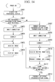
- FIG. 14 is a flowchart illustrating the operation procedure of the received image displaying apparatus 20 in the present preferred embodiment.
- Step S401 The terminal detection unit 340 searches for another apparatus included in the image transmitting/receiving system 1. Then, the procedure proceeds to a process of step S402.
- Step S402 The recognition unit 321 determines whether a reference synchronization signal transmitted from another apparatus has been received in the reception unit 302 during a constant period. When the recognition unit 321 determines that the reference synchronization signal transmitted from another apparatus has been received in the reception unit 302, the procedure proceeds to a process of step S403. Otherwise, the procedure proceeds to a process of step S407.
- Step S403 The communication control unit 310 waits until an image transmitting apparatuses 10 is connected. When the image transmitting apparatuses 10 is connected, the procedure proceeds to a process of step S404.
- Step S404 The reception unit 302 performs a communication connection with the image transmitting apparatuses 10 connected in the process of step S403. Then, the procedure proceeds to a process of step S405.
- Step S405 The reception unit 302 receives an image signal transmitted from the image transmitting apparatuses 10 for which the communication connection has been performed in the process of step S404. Then, the procedure proceeds to a process of step S406.
- Step S406 The display unit 370 displays a moving image based on the image signal received in the reception unit 302 in the process of step S405. Then, the procedure returns to the process of step S405. In addition, the reception unit 302 and the display unit 370 repeat the processes of step S405 and step S406 until the reception of the image signal is stopped, such as the reception of a reception stop instruction by the instruction input unit 190.
- Step S407 The control unit 320 allows the reference synchronization signal generation unit 330 to generate the reference synchronization signal.
- the reference synchronization signal generation unit 330 generates the reference synchronization signal.
- the reference synchronization signal generation unit 330 continuously generates the reference synchronization signal until the received image displaying apparatus 20 is powered off. Then, the procedure proceeds to a process of step 408.
- Step S408 The communication control unit 310 waits until an image transmitting apparatus 10 is connected. When the image transmitting apparatus 10 is connected, the procedure proceeds to a process of step S409.
- Step S409 The reception unit 302 performs a communication connection with the image transmitting apparatus 10 connected in the process of step S408. Then, the procedure proceeds to a process of step S410.
- Step S410 The reception unit 302 receives a frame of an image signal transmitted from the image transmitting apparatus 10 for which the communication connection has been performed in the process of step S409. Then, the procedure proceeds to a process of step S411.
- Step S411 The transmission unit 301 transmits ACK. Then, the procedure proceeds to a process of step 412
- Step S412 The recognition unit 321 recognizes whether the frame of the image signal received in the reception unit 302 in the process of step S410 is a frame immediately before a blanking interval.
- the recognition unit 321 recognizes that the frame received in the reception unit 302 in the process of step S410 is the frame immediately before the blanking interval. Otherwise, the procedure returns to the process of step S410.
- Step S413 The communication control unit 310 controls the transmission unit 301 to transmit the reference synchronization signal generated by the reference synchronization signal generation unit 330 to other image transmitting apparatuses 10 and other received image displaying apparatuses 20 included in the image transmitting/receiving system 1 in the form of a packet. Then, the procedure returns to the process of step S410.
- step S401 to step S413 when another apparatus transmits no reference synchronization signal, the received image displaying apparatus 20 is able to generate the reference synchronization signal and transmit the generated reference synchronization signal to other apparatuses in the blanking interval. Furthermore, the other apparatuses having received the reference synchronization signal are able to recognize the image signal transmission timing and the blanking interval based on the reference synchronization signal.
- FIG. 15 is a sequence diagram representing an operation procedure when switching a connection between the image transmitting apparatus 10 and the received image displaying apparatus 20 in the present preferred embodiment.
- a vertical axis indicates the passage of time.
- FIG. 15 illustrates a detailed example of the case in which, when the image transmitting apparatus 10-2 transmits an image signal to the received image displaying apparatuses 20-2 and 20-3 using a communication channel CH2, and the image transmitting apparatus 10-3 transmits an image signal to the received image displaying apparatus 20-4 using a communication channel CH3, a destination from which the received image displaying apparatus 20-3 receives the image signal is switched to the image transmitting apparatus 10-3.
- Step S501 The image transmitting apparatus 10-2 transmits an image signal to the received image displaying apparatuses 20-2 and 20-3, and the image transmitting apparatus 10-3 transmits an image signal to the received image displaying apparatus 20-4.
- the image transmitting apparatus 10-2 and the image transmitting apparatus 10-3 transmit the image signals according to the image signal transmission timing based on the reference signal as described above.
- the timing at which the image transmitting apparatus 10-2 transmits the image signal to the received image displaying apparatuses 20-2 and 20-3 is different from the timing at which the image transmitting apparatus 10-3 transmits the image signal to the received image displaying apparatus 20-4.
- this is for illustrative purposes only, and the image transmitting apparatus 10-2 and the image transmitting apparatus 10-3 actually transmit the image signals at the same timing.
- Step S502 The instruction input unit 360 of the received image displaying apparatus 20-3 receives the input of an instruction for switching a reception destination of the image signal from the image transmitting apparatus 10-2 to the image transmitting apparatus 10-3.
- Step S503 After a blanking interval starts, the received image displaying apparatus 20-3 transmits a switching confirmation message for asking permission to start communication with the image transmitting apparatus 10-3 to the image transmitting apparatus 10-2.
- Step S504 When the switching confirmation message is received in the process of step S503, the image transmitting apparatus 10-2 determines whether to permit the communication with the image transmitting apparatus 10-3, and transmits a switching permission message to the received image displaying apparatus 20-3 when it is determined to permit the communication.
- Step S505 The received image displaying apparatus 20-3 transmits a disconnection request message to the image transmitting apparatus 10-2.
- Step S506 The image transmitting apparatus 10-2 transmits a disconnection completion message to the received image displaying apparatus 20-3, and then disconnects a communication connection with the received image displaying apparatus 20-3.
- Step S507 The received image displaying apparatus 20-3 disconnects a communication connection with the image transmitting apparatus 10-2, and then switches a communication channel from the CH2 to the CH3.
- Step S508 The received image displaying apparatus 20-3 transmits a disconnection request message to the received image displaying apparatus 20-4.
- Step S509 The received image displaying apparatus 20-4 transmits a disconnection instruction message to the image transmitting apparatus 10-3, and then disconnects a communication connection with the image transmitting apparatus 10-3.
- Step S510 The received image displaying apparatus 20-4 transmits a disconnection completion message and information specifying a channel (a free channel) to be used later by the received image displaying apparatus 20-4 to the received image displaying apparatus 20-3, and then disconnects a communication connection with the image transmitting apparatus 10-3. Then, the received image displaying apparatus 20-4 changes a communication channel to the free channel.
- a channel a free channel
- Step S511 The received image displaying apparatus 20-3 transmits a connection request message to the image transmitting apparatus 10-3.
- Step S512 After starting a communication connection with the received image displaying apparatus 20-3, the image transmitting apparatus 10-3 transmits a connection completion message to the received image displaying apparatus 20-3.
- Step S513 The image transmitting apparatuses 10-2 and 10-3 and the received image displaying apparatuses 20-1, 20-2, and 20-3 perform update processes of pairing lists.
- the update processes of the pairing lists are the same as the update processes of the pairing lists in the first preferred embodiment.
- Step S514 The received image displaying apparatus 20-4 waits for a connection.
- Step S5-5 After the blanking interval ends, the image transmitting apparatus 10-2 transmits the image signal to the received image displaying apparatus 20-2, and the image transmitting apparatus 10-3 transmits the image signal to the received image displaying apparatus 20-3.
- the timing at which the image transmitting apparatus 10-2 transmits the image signal to the received image displaying apparatus 20-2 is different from the timing at which the image transmitting apparatus 10-3 transmits the image signal to the received image displaying apparatus 20-3.
- this is for illustrative purposes only, and the image transmitting apparatus 10-2 and the image transmitting apparatus 10-3 actually transmit the image signals at the same timing.
- step S501 to step S515 when switching a connection destination apparatus, the image transmitting apparatuses 10 and the received image displaying apparatuses 20 included in the image transmitting/receiving system 1 perform the transmission/reception of data required in order to switch the connection destination apparatus during the blanking interval. Consequently, it is possible to perform the switching of a communication connection without influencing the transmission/reception of an image signal.
- one of the received image displaying apparatuses 20 included in the image transmitting/receiving system 1 transmits the reference synchronization signal indicating the transmission timing of the image signal to the other received image displaying apparatuses 20 and the other image transmitting apparatuses 10. Then, all the image transmitting apparatuses 10 included in the image transmitting/receiving system 1 transmit the image signal based on the reference synchronization signal. In this way, all the image transmitting apparatuses 10 included in the image transmitting/receiving system 1 are able to allow the timing at which the image signal is transmitted to synchronize with the timing (the blanking interval) at which the image signal is not transmitted.
- the image transmitting apparatuses 10 and the received image displaying apparatuses 20 included in the image transmitting/receiving system 1 perform the transmission/reception of data required in order to switch the connection destination apparatus during the blanking interval. Consequently, it is possible to perform the switching of a communication connection without influencing the transmission/reception of an image signal.
- an image transmitting/receiving system 1 an image transmitting apparatus 10, and a received image displaying apparatus 20 have the same configurations as those of the image transmitting/receiving system 1, the image transmitting apparatus 10, and the received image displaying apparatus 20 of the third preferred embodiment.
- FIG. 16 is a flowchart illustrating the operation procedure of the image transmitting apparatus 10 in the present preferred embodiment.
- Processes of step S601 to step S612 are the same as the processes of step S401 to step S412 in the third preferred embodiment.
- Step S613 The control unit 320 determines whether there is a channel through which the reference synchronization signal is not transmitted. When the control unit 320 determines that there is a channel through which the reference synchronization signal is not transmitted, the procedure proceeds to a process of step S614. When the control unit 320 determines that there is no channel through which the reference synchronization signal is not transmitted, the procedure returns to the process of step S610.
- Step S614 The communication control unit 310 changes a communication channel of the transmission unit 301 to the channel through which the reference synchronization signal is not transmitted. Then, the procedure proceeds to a process of step S615.
- Step S615 The communication control unit 310 controls the transmission unit 301 to transmit the reference synchronization signal generated by the reference synchronization signal generation unit 330 in the form of a packet using the channel set in the process of step S614. Then, the procedure proceeds to a process of step S616.
- Step S616 The control unit 320 determines whether the reference synchronization signal has been transmitted to all channels. When the control unit 320 determines that the reference synchronization signal has been transmitted to all the channels, the procedure proceeds to a process of step S620. Otherwise, the procedure proceeds to a process of step S617.
- Step S617 The recognition unit 321 recognizes whether the blanking interval has ended based on the reference synchronization signal generated by the reference synchronization signal generation unit 330. When the recognition unit 321 recognizes that the blanking interval has ended, the procedure proceeds to a process of step S619. Otherwise, the procedure proceeds to a process of step S618.
- Step S618 The communication control unit 310 changes the communication channel of the transmission unit 301 to the channel through which the reference synchronization signal is not transmitted. Then, the procedure returns to the process of step S615.
- Step S619 The control unit 320 allows the channel through which the reference synchronization signal is not transmitted to be stored in the storage unit 350. Then, the procedure proceeds to a process of step S620.
- Step S620 The communication control unit 310 returns the communication channel of the transmission unit 301 to the original channel. Then, the procedure returns to the process of step S610.
- one of the received image displaying apparatuses 20 included in the image transmitting/receiving system 1 is able to transmit the reference synchronization signal to all the channels within the blanking interval.
- FIG. 17 is a schematic diagram representing the configuration of an image transmitting/receiving system in the present preferred embodiment.
- an image transmitting/receiving system 2 includes image transmitting apparatuses 10-1 to 10-3, received image displaying apparatuses 20-1 to 20-4, and a remote control apparatus 30.
- the image transmitting apparatus 10 and the received image displaying apparatus 20 have the same configurations as those of the image transmitting apparatus 10 and the received image displaying apparatus 20 of the first preferred embodiment.
- the remote control apparatus 30 receives the input of an instruction from a user, and transmits an instruction to other apparatuses included in the image transmitting/receiving system 2 based on the received instruction.
- FIG. 18 is a block diagram representing the configuration of the remote control apparatus 30 in the present preferred embodiment.
- the remote control apparatus 30 includes a storage unit 510, a reference synchronization signal generation unit 520, a control unit 530, a terminal detection unit 540, a communication control unit 550, a wireless unit 560 (a wireless communication unit), an instruction input unit 570, and a display unit 580.
- the storage unit 510 includes a list management unit 511.
- the list management unit 511 stores a pairing list indicating combinations of the image transmitting apparatuses 10 and the received image displaying apparatuses 20, which perform communication.
- the reference synchronization signal generation unit 520 generates a reference synchronization signal indicating a transmission timing of an image signal in all the image transmitting apparatuses 10 included in the image transmitting/receiving system 2.
- the control unit 530 performs the control of each element provided in the remote control apparatus 30. Furthermore, the control unit 530 includes a recognition unit 531 that recognizes a timing at which an image signal is transmitted, and a blanking interval, which indicates a timing at which control data is transmitted, based on the reference synchronization signal.
- the terminal detection unit 540 searches for another apparatus included in the image transmitting/receiving system 2.
- the communication control unit 550 performs the communication control (a baseband process).
- the wireless unit 560 includes a transmission unit 561 and a reception unit 562.
- the transmission unit 561 wirelessly transmits data to another apparatus through an antenna (not illustrated).
- the reception unit 562 wirelessly receives data wirelessly transmitted from another apparatus through an antenna (not illustrated).
- the instruction input unit 570 includes a keyboard, a switch and the like, and receives instruction input from a user.
- the display unit 580 includes a liquid crystal display and the like, and displays various types of information.
- FIG. 19 is a flowchart illustrating the operation procedure of the remote control apparatus 30 in the present preferred embodiment.
- Step S701 The terminal detection unit 540 searches for another apparatus included in the image transmitting/receiving system 2. Then, the procedure proceeds to a process of step S702.
- Step S702 The recognition unit 531 determines whether an apparatus capable of transmitting/receiving an image signal is included in the image transmitting/receiving system 2 based on a result obtained by searching for another apparatus in the process of step S701.
- the recognition unit 531 determines that the apparatus capable of transmitting/receiving the image signal is included in the image transmitting/receiving system 2
- the procedure proceeds to a process of step S703. Otherwise, the procedure returns to the process of step S701.
- Step S703 The recognition unit 531 determines whether a reference synchronization signal transmitted from another apparatus has been received in the reception unit 562 during a constant period. When the recognition unit 531 determines that a reference synchronization signal transmitted from another apparatus has been received in the reception unit 562, the procedure proceeds to a process of step S704. Otherwise, the procedure proceeds to a process of step S709.
- Step S704 The communication control unit 550 matches a reception channel of the reception unit 562 with a channel through which the reference synchronization signal has been transmitted in order to receive the reference synchronization signal. Then, the procedure proceeds to a process of step S705.
- Step S705 The reception unit 562 receives a reference synchronization signal transmitted from the other apparatus. Furthermore, the recognition unit 531 recognizes a timing of a blanking interval based on the reference synchronization signal received in the reception unit 562. Then, the procedure proceeds to a process of step S706.
- Step S706 The control unit 530 determines whether an instruction has been input to the instruction input unit 570. When the control unit 530 determines that an instruction has been input to the instruction input unit 570, the procedure proceeds to a process of step S707. Otherwise, the control unit 530 performs the process of step S706 again.
- Step S707 The recognition unit 531 recognizes whether a current time point is a blanking interval based on the reference synchronization signal received in the reception unit 562 in the process of step S705. When the recognition unit 531 recognizes that the current time point is the blanking interval, the procedure proceeds to a process of step S708. Otherwise, the recognition unit 531 performs the process of step S707 again.
- Step S708 The communication control unit 550 controls the transmission unit 561 to transmit a message based on the instruction input to the instruction input unit 570 in the process of step S706 to another apparatus (the image transmitting apparatus 10 and the received image displaying apparatus 20). Then, the procedure returns to the process of step S706.
- Step S709 The control unit 530 allows the reference synchronization signal generation unit 520 to generate the reference synchronization signal.
- the reference synchronization signal generation unit 520 generates the reference synchronization signal. Then, the procedure proceeds to a process of step S710. In addition, the reference synchronization signal generation unit 520 continuously generates the reference synchronization signal until the remote control apparatus 30 is powered off.
- Step S710 The communication control unit 550 acquires display information (the size of image data and the number of frames) from the apparatus capable of transmitting/receiving an image signal based on the result obtained by searching for the terminal detection unit 540 in the process of step S701. Then, the procedure proceeds to a process of step S711.
- Step S711 The communication control unit 550 controls the transmission unit 561 to transmit the reference synchronization signal generated by the reference synchronization signal generation unit 520 to other apparatuses included in the image transmitting/receiving system 2 in the form of a packet. Then, the procedure proceeds to a process of step S712.
- Step S712 The control unit 530 determines whether the reference synchronization signal has been transmitted to all channels. When the control unit 530 determines that the reference synchronization signal has been transmitted to all the channels, the procedure proceeds to a process of step S715. Otherwise, the procedure proceeds to a process of step S713.
- Step S713 The recognition unit 531 recognizes whether the blanking interval has ended based on the reference synchronization signal generated by the reference synchronization signal generation unit 520. When the recognition unit 531 recognizes that the blanking interval has ended, the procedure proceeds to a process of step S715. Otherwise, the procedure proceeds to a process of step S714.
- Step S714 The communication control unit 550 changes the communication channel of the transmission unit 561 to a channel through which the reference synchronization signal is not transmitted. Then, the procedure returns to the process of step S712.
- Step S715 The communication control unit 550 returns the communication channel of the transmission unit 561 to the original channel. Then, the procedure proceeds to a process of step S716.
- Step S716 The control unit 530 determines whether an instruction has been input to the instruction input unit 570. When the control unit 530 determines that the instruction has been input to the instruction input unit 570, the procedure proceeds to a process of step S707. Otherwise, the control unit 530 performs the process of step S706 again.
- Step S717 The recognition unit 531 recognizes whether a current time point is a blanking interval based on the reference synchronization signal generated by the reference synchronization signal generation unit 520. When the recognition unit 531 recognizes that the current time point is the blanking interval, the procedure proceeds to a process of step S718. Otherwise, the recognition unit 531 performs the process of step S717 again.
- Step S718 The communication control unit 550 controls the transmission unit 561 to transmit a message based on the instruction input to the instruction input unit 570 in the process of step S716 to another apparatus (the image transmitting apparatus 10 and the received image displaying apparatus 20). Then, the procedure returns to the process of step S711.
- step S701 to step S718 when another apparatus transmits no reference synchronization signal, the remote control apparatus 30 is able to generate the reference synchronization signal and transmit the generated reference synchronization signal to other apparatuses in the blanking interval. Furthermore, the other apparatuses having received the reference synchronization signal are able to recognize the image signal transmission timing and the blanking interval based on the reference synchronization signal.
- FIG. 20 is a sequence diagram representing an operation procedure when switching a connection between the image transmitting apparatus 10 and the received image displaying apparatus 20 in the present preferred embodiment.
- a vertical axis indicates the passage of time.
- FIG. 20 illustrates a detailed example of the case in which, when the image transmitting apparatus 10-2 transmits an image signal to the received image displaying apparatuses 20-2 and 20-3 using a communication channel CH2, and the image transmitting apparatus 10-3 transmits an image signal to the received image displaying apparatus 20-4 using a communication channel CH3, a destination to which the image transmitting apparatus 10-3 transmits an image signal is switched to the received image displaying apparatus 20-3 based on a switching instruction of the remote control apparatus 30.
- Step S801 The image transmitting apparatus 10-2 transmits an image signal to the received image displaying apparatuses 20-2 and 20-3, and the image transmitting apparatus 10-3 transmits an image signal to the received image displaying apparatus 20-4.
- the timing at which the image transmitting apparatus 10-2 transmits the image signal to the received image displaying apparatuses 20-2 and 20-3 is different from the timing at which the image transmitting apparatus 10-3 transmits the image signal to the received image displaying apparatus 20-4.
- this is for illustrative purposes only, and the image transmitting apparatus 10-2 and the image transmitting apparatus 10-3 actually transmit the image signals at the same timing.
- Step S802 The instruction input unit 570 of the remote control apparatus 30 receives the input of an instruction for switching a destination to which the image transmitting apparatus 10-3 transmits an image signal to the received image displaying apparatus 20-3.
- Step S803 The remote control apparatus 30 transmits a switching instruction message to the image transmitting apparatus 10-3.
- Step S804 The remote control apparatus 30 transmits a disconnection instruction message to the received image displaying apparatus 20-4.
- Step S805 The received image displaying apparatus 20-4 transmits the disconnection instruction message to the image transmitting apparatus 10-3, and then disconnects a connection with the image transmitting apparatus 10-3. Furthermore, the image transmitting apparatus 10-3 disconnects a connection with the received image displaying apparatus 20-4.
- Step S806 The received image displaying apparatus 20-4 transmits a disconnection completion message to the remote control apparatus 30.
- Step S807 The remote control apparatus 30 transmits a channel change instruction message to the image transmitting apparatus 10-3.
- Step S808 The remote control apparatus 30 and the image transmitting apparatus 10-3 switch a communication channel from the CH3 to the CH2.
- Step S809 The remote control apparatus 30 transmits a disconnection instruction message to the received image displaying apparatus 20-3.
- Step S810 The received image displaying apparatus 20-3 transmits the disconnection instruction message to the image transmitting apparatus 10-2, and then disconnects a connection with the image transmitting apparatus 10-2. Furthermore, the image transmitting apparatus 10-2 disconnects a connection with the received image displaying apparatus 20-3.
- Step S811 The received image displaying apparatus 20-3 transmits a disconnection completion message to the remote control apparatus 30.
- Step S812 The remote control apparatus 30 transmits connection setting information of the received image displaying apparatus 20-3 to the image transmitting apparatus 10-3.
- Step S813 The image transmitting apparatus 10-3 prepares a connection with the received image displaying apparatus 20-3 based on the connection setting information transmitted in the process of step S812, and then transmits a preparation completion message to the remote control apparatus 30.
- Step S814 The remote control apparatus 30 transmits a message for instructing a connection with the received image displaying apparatus 20-3 to the image transmitting apparatus 10-3.
- Step S815) The image transmitting apparatus 10-3 performs a communication connection with the received image displaying apparatus 20-3, and then transmits a connection completion message to the remote control apparatus 30.
- Step S816 The received image displaying apparatus 20-4 transmits information specifying a channel (a free channel) to be used later by the received image displaying apparatus 20-4 to the remote control apparatus 30, changes a communication channel to the free channel, and then waits for a connection.
- a channel a free channel
- Step S817) The remote control apparatus 30 updates a communication channel, which is stored in the pairing list and used by the received image displaying apparatus 20-4, based on the information received in the process of step S816 and specifying the channel (the free channel) to be used later by the received image displaying apparatus 20-4.
- Step S8128 The image transmitting apparatuses 10-2 and 10-3, the received image displaying apparatuses 20-2 to 20-4, and the remote control apparatus 30 perform update processes of pairing lists.
- Step S819) After the blanking interval ends, the image transmitting apparatus 10-2 transmits the image signal to the received image displaying apparatus 20-2, and the image transmitting apparatus 10-3 transmits the image signal to the received image displaying apparatus 20-3.
- the timing at which the image transmitting apparatus 10-2 transmits the image signal to the received image displaying apparatus 20-2 is different from the timing at which the image transmitting apparatus 10-3 transmits the image signal to the received image displaying apparatus 20-3.
- this is for illustrative purposes only, and the image transmitting apparatus 10-2 and the image transmitting apparatus 10-3 actually transmit the image signals at the same timing.
- step S801 to step S819 when switching a connection destination apparatus, the image transmitting apparatuses 10, the received image displaying apparatuses 20, and the remote control apparatus 30 included in the image transmitting/receiving system 2 perform the transmission/reception of data required in order to switch the connection destination apparatus during the blanking interval. Consequently, it is possible to perform the switching of a communication connection without influencing the transmission/reception of an image signal.
- the remote control apparatus 30 included in the image transmitting/receiving system 2 transmits the reference synchronization signal indicating the transmission timing of the image signal to the image transmitting apparatuses 10. Then, all the image transmitting apparatuses 10 included in the image transmitting/receiving system 2 transmit the image signal based on the reference synchronization signal. In this way, all the image transmitting apparatuses 10 included in the image transmitting/receiving system 2 are able to allow the timing at which the image signal is transmitted to synchronize with the timing (the blanking interval) at which the image signal is not transmitted.
- the image transmitting apparatuses 10 when switching a connection destination apparatus, the image transmitting apparatuses 10, the received image displaying apparatuses 20, and the remote control apparatus 30 included in the image transmitting/receiving system 2 perform the transmission/reception of data required in order to switch the connection destination apparatus during the blanking interval. Consequently, it is possible to perform the switching of a communication connection without influencing the transmission/reception of an image signal.
- the image transmitting/receiving system 1 includes three image transmitting apparatuses 10 and four received image displaying apparatuses 20.
- the image transmitting/receiving system 1 may include one or more image transmitting apparatuses 10 and one or more received image displaying apparatuses 20.
- the image transmitting/receiving system 2 includes three image transmitting apparatuses 10, four received image displaying apparatuses 20, and one remote control apparatus 30.
- the image transmitting/receiving system 2 may include one or more image transmitting apparatuses 10, one or more received image displaying apparatuses 20, and one or more remote control apparatuses 30.
- the present invention can be extensively applied to an image transmitting/receiving system, an image transmitting apparatus, a received image displaying apparatus, and a wireless control apparatus, and can perform the switching of a communication connection without influencing the transmission/reception of an image signal.
Landscapes
- Engineering & Computer Science (AREA)
- Multimedia (AREA)
- Signal Processing (AREA)
- Computer Networks & Wireless Communication (AREA)
- Theoretical Computer Science (AREA)
- Human Computer Interaction (AREA)
- Physics & Mathematics (AREA)
- General Engineering & Computer Science (AREA)
- General Physics & Mathematics (AREA)
- Two-Way Televisions, Distribution Of Moving Picture Or The Like (AREA)
- Controls And Circuits For Display Device (AREA)
Claims (26)
- Système (1, 2) de transmission/réception d'images comprenant :une pluralité d'appareils (10, 10-1, 10-2, 10-3) de transmission d'images dont chacun transmet sans fil de manière continue des images de trame capturées dans un ordre de capture ; etune pluralité d'appareils (20, 20-1, 20-2, 20-3, 20-4) d'affichage d'images reçues dont chacun reçoit sans fil de manière continue les images de trame transmises sans fil de manière continue par la pluralité d'appareils de transmission d'images et affiche de manière continue les images de trame reçues dans l'ordre de capture, dans lequell'appareil (10, 10-1, 10-2, 10-3) de transmission d'images comprend :une unité de communication sans fil (181, 301, 561) qui transmet sans fil l'image de trame vers l'appareil d'affichage d'images reçues, qui a établi une connexion de communication sans fil avec l'appareil de transmission d'images, en synchronisation avec un signal de synchronisation de référence, l'appareil (20, 20-1, 20-2, 20-3, 20-4) d'affichage d'images reçues comprend :dans lequel au moins un appareil parmi l'appareil (10, 10-1, 10-2, 10-3) de transmission d'images et l'appareil (20, 20-1, 20-2, 20-3, 20-4) d'affichage d'images reçues contenus dans le système (1, 2) de transmission/réception d'images comprend :une unité de communication sans fil (182, 302, 562) qui reçoit sans fil les images de trame transmises depuis l'appareil de transmission d'images ayant établi une connexion de communication sans fil avec l'appareil d'affichage d'images reçues ; etune unité d'affichage (200, 370, 580) qui affiche les images de trame, qui ont été reçues sans fil dans l'unité de communication sans fil, dans l'ordre de capture des images de trame,une unité (140, 330, 520) de génération de signal de synchronisation de référence qui génère un signal de synchronisation de référence ; etune unité de commande (150, 320, 530) quidans lequel au moins un appareil parmi l'appareil de transmission d'images et l'appareil d'affichage d'images reçues comprend :commande l'unité de génération de signal de synchronisation de référence de l'appareil dans lequel l'unité de commande est contenue pour générer le signal de synchronisation de référence, etcommande l'unité de communication sans fil de l'appareil dans lequel l'unité de commande est contenue pour transmettre sans fil le signal de synchronisation de référence vers un autre appareil contenu dans le système (1, 2) de transmission/réception d'images, si l'unité de communication sans fil de l'appareil, dans lequel l'unité de commande est contenue, n'a pas reçu le signal de synchronisation de référence après qu'une période de temps prédéterminée se soit écoulée, etune unité (151, 321, 531) de reconnaissance d'intervalle de suppression qui reconnaît un intervalle de suppression vertical de l'image de trame ; etune unité (170, 310, 550) de commande de déconnexion qui commande l'unité de communication sans fil de l'appareil comprenant l'unité (170, 310, 550) de commande de déconnexion pour démarrer un processus consistant à déconnecter la connexion de communication sans fil établie à l'intérieur d'une période de l'intervalle de suppression vertical reconnu par l'unité de reconnaissance d'intervalle de suppression, dans lequelle processus de déconnexion de la connexion de communication sans fil établie comprend :un premier appareil (10-3) de transmission d'images parmi la pluralité d'appareils de transmission d'images transmettant un message de demande de connexion vers un premier appareil (20-3) d'affichage d'images reçues parmi la pluralité d'appareils d'affichage d'images reçues,le premier appareil (20-3) d'affichage d'images reçues transmettant un message de demande de déconnexion vers un deuxième appareil (10-2) de transmission d'images parmi la pluralité d'appareils de transmission d'images,le deuxième appareil (10-2) de transmission d'images transmettant un message de déconnexion vers le premier appareil (20-3) d'affichage d'images reçues, et déconnectant ensuite une connexion de communication avec le premier appareil (20-3) d'affichage d'images reçues,le premier appareil (20-3) d'affichage d'images reçues déconnectant une connexion de communication avec le deuxième appareil (10-2) de transmission d'images, et transmettant ensuite un message de fin de déconnexion vers le premier appareil (10-3) de transmission d'images,le premier appareil (10-3) de transmission d'images et le premier appareil (20-3) d'affichage d'images reçues commutant un canal de communication,le premier appareil (10-3) de transmission d'images transmettant un message de demande de déconnexion vers un deuxième appareil (20-4) d'affichage d'images reçues parmi la pluralité d'appareils d'affichage d'images reçues, etle deuxième appareil (20-4) d'affichage d'images reçues transmettant un message de fin de déconnexion vers le premier appareil (10-3) de transmission d'images, et déconnectant ensuite une connexion de communication avec le premier appareil (10-3) de transmission d'images ; oule processus de déconnexion de la connexion de communication sans fil établie comprend :le premier appareil (20-3) d'affichage d'images reçues transmettant un message de demande de déconnexion vers le deuxième appareil (10-2) de transmission d'images,le deuxième appareil (10-2) de transmission d'images transmettant un message de déconnexion vers le premier appareil (20-3) d'affichage d'images reçues, et déconnectant ensuite une connexion de communication avec le premier appareil (20-3) d'affichage d'images reçues,le premier appareil (20-3) d'affichage d'images reçues commutant un canal de communication,le premier appareil (20-3) d'affichage d'images reçues transmettant un message de demande de déconnexion vers le deuxième appareil (20-4) d'affichage d'images reçues,le deuxième appareil (20-4) d'affichage d'images reçues transmettant un message d'instruction d'interruption vers le premier appareil (10-3) de transmission d'images et déconnectant ensuite une connexion de communication avec le premier appareil (10-3) de transmission d'images, etle deuxième appareil (20-4) d'affichage d'images reçues transmettant un message de fin de déconnexion vers le premier appareil (20-3) de transmission d'images reçues, et déconnectant ensuite une connexion de communication avec le premier appareil (20-3) de transmission d'images reçues.
- Système de transmission/réception d'images selon la revendication 1, dans lequel l'unité (170, 310, 550) de commande de déconnexion, qui est prévue dans au moins l'un parmi l'appareil (10, 10-1, 10-2, 10-3) de transmission d'images et l'appareil (20, 20-1, 20-2, 20-3, 20-4) d'affichage d'images reçues, commande l'unité de communication sans fil de l'appareil comprenant l'unité (170, 310, 550) de commande de déconnexion pour ne pas réaliser le processus de déconnexion de la connexion de communication sans fil établie en dehors de l'intervalle de suppression vertical.
- Système de transmission/réception d'images selon la revendication 1, dans lequel l'unité (151, 321, 531) de reconnaissance d'intervalle de suppression reconnaît l'intervalle de suppression vertical sur la base de l'image de trame ou du signal de synchronisation de référence.
- Appareil (10, 10-1, 10-2, 10-3) de transmission d'images pour utilisation dans un système (1, 2) de transmission/réception d'images qui comprend : une pluralité d'appareils de transmission d'images dont chacun transmet sans fil de manière continue des image de trame capturées dans un ordre de capture ; et une pluralité d'appareils (20, 20-1, 20-2, 20-3, 20-4) d'affichage d'images reçues dont chacun reçoit sans fil de manière continue les images de trame transmises sans fil de manière continue par la pluralité d'appareils de transmission d'image et affiche de manière continue les images de trame reçues dans l'ordre de capture, l'appareil (10, 10-1, 10-2, 10-3) de transmission d'images comprenant :une unité de communication sans fil (181, 301, 561) qui transmet sans fil l'image de trame vers l'appareil d'affichage d'images reçues, qui a établi une connexion de communication sans fil avec l'appareil de transmission d'images, en synchronisation avec un signal de synchronisation de référence,une unité (140, 330, 520) de génération de signal de synchronisation de référence qui génère un signal de synchronisation de référence ;une unité de commande (150, 320, 530) quicommande l'unité de génération de signal de synchronisation de référence pour générer le signal de synchronisation de référence, etcommande l'unité de communication sans fil pour transmettre sans fil le signal de synchronisation de référence vers un autre appareil contenu dans le système de transmission/réception d'images, si l'unité de communication sans fil n'a pas reçu le signal de synchronisation de référence après qu'une période de temps prédéterminée se soit écoulée, etune unité (151, 321, 531) de reconnaissance d'intervalle de suppression qui reconnaît un intervalle de suppression vertical de l'image de trame ; etune unité (170, 310, 550) de commande de déconnexion qui commande l'unité de communication sans fil pour démarrer un processus consistant à déconnecter la connexion de communication sans fil établie à l'intérieur d'une période de l'intervalle de suppression vertical reconnu par l'unité de reconnaissance d'intervalle de suppression, dans lequelle processus de déconnexion de la connexion de communication sans fil établie comprend :un premier appareil (10-3) de transmission d'images parmi la pluralité d'appareils de transmission d'images transmettant un message de demande de connexion vers un premier appareil (20-3) d'affichage d'images reçues parmi la pluralité d'appareils d'affichage d'images reçues,le premier appareil (20-3) d'affichage d'images reçues transmettant un message de demande de déconnexion vers un deuxième appareil (10-2) de transmission d'images parmi la pluralité d'appareils de transmission d'images,le deuxième appareil (10-2) de transmission d'images transmettant un message de déconnexion vers le premier appareil (20-3) d'affichage d'images reçues, et déconnectant ensuite une connexion de communication avec le premier appareil (20-3) d'affichage d'images reçues,le premier appareil (20-3) d'affichage d'images reçues déconnectant une connexion de communication avec le deuxième appareil (10-2) de transmission d'images, et transmettant ensuite un message de fin de déconnexion vers le premier appareil (10-3) de transmission d'images,le premier appareil (10-3) de transmission d'images et le premier appareil (20-3) d'affichage d'images reçues commutant un canal de communication,le premier appareil (10-3) de transmission d'images transmettant un message de demande de déconnexion vers un deuxième appareil (20-4) d'affichage d'images reçues parmi la pluralité d'appareils d'affichage d'images reçues, etle deuxième appareil (20-4) d'affichage d'images reçues transmettant un message de fin de déconnexion vers le premier appareil (10-3) de transmission d'images, et déconnectant ensuite une connexion de communication avec le premier appareil (10-3) de transmission d'images ; oule processus de déconnexion de la connexion de communication sans fil établie comprend :le premier appareil (20-3) d'affichage d'images reçues transmettant un message de demande de déconnexion vers le deuxième appareil (10-2) de transmission d'images,le deuxième appareil (10-2) de transmission d'images transmettant un message de déconnexion vers le premier appareil (20-3) d'affichage d'images reçues, et déconnectant ensuite une connexion de communication avec le premier appareil (20-3) d'affichage d'images reçues,le premier appareil (20-3) d'affichage d'images reçues commutant un canal de communication,le premier appareil (20-3) d'affichage d'images reçues transmettant un message de demande de déconnexion vers le deuxième appareil (20-4) d'affichage d'images reçues,le deuxième appareil (20-4) d'affichage d'images reçues transmettant un message d'instruction d'interruption vers le premier appareil (10-3) de transmission d'images et déconnectant ensuite une connexion de communication avec le premier appareil (10-3) de transmission d'images, etle deuxième appareil (20-4) d'affichage d'images reçues transmettant un message de fin de déconnexion vers le premier appareil (20-3) de transmission d'images reçues, et déconnectant ensuite une connexion de communication avec le premier appareil (20-3) de transmission d'images reçues.
- Appareil (10, 10-1, 10-2, 10-3) de transmission d'images selon la revendication 4, dans lequel l'unité de commande (150, 320, 530) commande l'unité de communication sans fil pour transmettre le signal de synchronisation de référence à l'intérieur de l'intervalle de suppression vertical.
- Appareil (10, 10-1, 10-2, 10-3) de transmission d'images selon la revendication 4, comprenant en outre :une unité de détection qui détecte une pluralité de canaux de communication utilisés lorsqu'un autre appareil de transmission d'images contenu dans le système de transmission/réception d'images transmet sans fil l'image de trame, dans lequell'unité de commande (150, 320, 530) commande l'unité de communication sans fil pour transmettre le signal de synchronisation de référence par l'intermédiaire de chaque canal de communication détecté par l'unité de détection.
- Appareil (10, 10-1, 10-2, 10-3) de transmission d'images selon la revendication 6, dans lequel,
lorsque l'unité de détection détecte la pluralité de canaux de communication, l'unité de commande (150, 320, 530) commande l'unité de communication sans fil pour transmettre le signal de synchronisation de référence par l'intermédiaire uniquement de certains parmi la pluralité de canaux de communication détectés par l'unité de détection, dans un intervalle de suppression vertical unique. - Appareil (10, 10-1, 10-2, 10-3) de transmission d'images selon la revendication 7, dans lequel l'unité de communication sans fil est commandée pour transmettre le signal de synchronisation de référence par l'intermédiaire de l'un parmi la pluralité de canaux de communication détectés par l'unité de détection, dans l'intervalle de suppression vertical unique.
- Appareil (10, 10-1, 10-2, 10-3) de transmission d'images selon la revendication 4, comprenant en outre :une unité de réception d'instruction qui reçoit une instruction d'ajout, de modification, et de suppression d'une destination de transmission de l'image de trame, dans lequel,lorsque l'unité de réception d'instruction reçoit l'instruction, l'unité (170, 310, 550) de commande de déconnexion commande l'unité de communication sans fil pour démarrer le processus de déconnexion de la connexion de communication sans fil établie.
- Appareil (10, 10-1, 10-2, 10-3) de transmission d'images selon la revendication 9, comprenant en outre :une unité d'opération (190, 360, 570) qui reçoit une opération par un utilisateur, dans laquelle l'unité de réception d'instruction reçoit l'instruction sur la base de l'opération reçue dans l'unité d'opération (190, 360, 570).
- Appareil (10, 10-1, 10-2, 10-3) de transmission d'images selon la revendication 9, dans lequel l'unité de réception d'instruction reçoit l'instruction depuis un autre appareil contenu dans le système de transmission/réception d'images par l'intermédiaire de l'unité de communication.
- Appareil (10, 10-1, 10-2, 10-3) de transmission d'images selon la revendication 4, dans lequel l'unité de commande de déconnexion (170, 310, 550) commande l'unité de communication sans fil pour ne pas réaliser le processus de déconnexion de la connexion de communication sans fil établie en dehors de l'intervalle de suppression vertical.
- Appareil (20, 20-1, 20-2, 20-3, 20-4) d'affichage d'images reçues pour utilisation dans un système (1, 2) de transmission/réception d'images qui comprend : une pluralité d'appareils (10, 10-1, 10-2, 10-3) de transmission d'images dont chacun transmet sans fil de manière continue des images de trame capturées dans un ordre de capture ; et une pluralité d'appareils (20, 20-1, 20-2, 20-3, 20-4) d'affichage d'images reçues dont chacun reçoit sans fil de manière continue les images de trame transmises sans fil de manière continue par la pluralité d'appareils de transmission d'images et affiche de manière continue les images de trame reçues dans l'ordre de capture, l'appareil d'affichage d'images reçues comprenant :une unité de communication sans fil (182, 302, 562) qui reçoit sans fil les images de trame transmises depuis l'appareil de transmission d'images ayant établi une connexion de communication sans fil avec l'appareil d'affichage d'images reçues ;une unité d'affichage qui affiche les images de trame reçues sans fil dans l'unité de communication sans fil, dans l'ordre de capture des images de trame,une unité (140, 330, 520) de génération de signal de synchronisation de référence qui génère un signal de synchronisation de référence ;une unité de commande (150, 320, 530) quicommande l'unité de génération de signal de synchronisation de référence pour générer le signal de synchronisation de référence, etcommande l'unité de communication sans fil pour transmettre sans fil le signal de synchronisation de référence vers un autre appareil contenu dans le système de transmission/réception d'images, si l'unité de communication sans fil n'a pas reçu le signal de synchronisation de référence après qu'une période de temps prédéterminée se soit écoulée ;une unité de reconnaissance d'intervalle de suppression qui reconnaît un intervalle de suppression vertical de l'image de trame ; etune unité (170, 310, 550) de commande de déconnexion qui commande l'unité de communication sans fil pour démarrer un processus consistant à déconnecter la connexion de communication sans fil établie à l'intérieur d'une période de l'intervalle de suppression vertical reconnu par l'unité de reconnaissance d'intervalle de suppression, dans lequelle processus de déconnexion de la connexion de communication sans fil établie comprend :un premier appareil (10-3) de transmission d'images parmi la pluralité d'appareils de transmission d'images transmettant un message de demande de connexion vers un premier appareil (20-3) d'affichage d'images reçues parmi la pluralité d'appareils d'affichage d'images reçues,le premier appareil (20-3) d'affichage d'images reçues transmettant un message de demande de déconnexion vers un deuxième appareil (10-2) de transmission d'images parmi la pluralité d'appareils de transmission d'images,le deuxième appareil (10-2) de transmission d'images transmettant un message de déconnexion vers le premier appareil (20-3) d'affichage d'images reçues, et déconnectant ensuite une connexion de communication avec le premier appareil (20-3) d'affichage d'images reçues,le premier appareil (20-3) d'affichage d'images reçues déconnectant une connexion de communication avec le deuxième appareil (10-2) de transmission d'images, et transmettant ensuite un message de fin de déconnexion vers le premier appareil (10-3) de transmission d'images,le premier appareil (10-3) de transmission d'images et le premier appareil (20-3) d'affichage d'images reçues commutant un canal de communication,le premier appareil (10-3) de transmission d'images transmettant un message de demande de déconnexion vers un deuxième appareil (20-4) d'affichage d'images reçues parmi la pluralité d'appareils d'affichage d'images reçues, etle deuxième appareil (20-4) d'affichage d'images reçues transmettant un message de fin de déconnexion vers le premier appareil (10-3) de transmission d'images, et déconnectant ensuite une connexion de communication avec le premier appareil (10-3) de transmission d'images ; oule processus de déconnexion de la connexion de communication sans fil établie comprend :le premier appareil (20-3) d'affichage d'images reçues transmettant un message de demande de déconnexion vers le deuxième appareil (10-2) de transmission d'images,le deuxième appareil (10-2) de transmission d'images transmettant un message de déconnexion vers le premier appareil (20-3) d'affichage d'images reçues, et déconnectant ensuite une connexion de communication avec le premier appareil (20-3) d'affichage d'images reçues,le premier appareil (20-3) d'affichage d'images reçues commutant un canal de communication,le premier appareil (20-3) d'affichage d'images reçues transmettant un message de demande de déconnexion vers le deuxième appareil (20-4) d'affichage d'images reçues,le deuxième appareil (20-4) d'affichage d'images reçues transmettant un message d'instruction d'interruption vers le premier appareil (10-3) de transmission d'images et déconnectant ensuite une connexion de communication avec le premier appareil (10-3) de transmission d'images, etle deuxième appareil (20-4) d'affichage d'images reçues transmettant un message de fin de déconnexion vers le premier appareil (20-3) de transmission d'images reçues, et déconnectant ensuite une connexion de communication avec le premier appareil (20-3) de transmission d'images reçues.
- Appareil (20, 20-1, 20-2, 20-3, 20-4) d'affichage d'images reçues selon la revendication 13, dans lequel l'unité de communication sans fil (182, 302, 562) reçoit sans fil les images de trame sous la forme de données en paquets, et l'unité de génération de signal de synchronisation de référence génère le signal de synchronisation de référence sur la base des données en paquets, qui indiquent des données finales de chaque trame des images de trame, parmi les données en paquets reçues sans fil dans l'unité de communication sans fil.
- Appareil (20, 20-1, 20-2, 20-3, 20-4) d'affichage d'images reçues selon la revendication 13, dans lequel l'unité de commande (150, 320, 530) commande l'unité de communication sans fil pour transmettre sans fil le signal de synchronisation de référence généré par l'unité de génération de signal de synchronisation de référence, conformément aux données en paquets indiquant une réponse pour les données en paquets, qui indiquent des données finales de chaque trame des images de trame, parmi les données en paquets reçues sans fil dans l'unité de communication sans fil.
- Appareil (20, 20-1, 20-2, 20-3, 20-4) d'affichage d'images reçues selon la revendication 13, dans lequel l'unité de communication sans fil (182, 302, 562) reçoit sans fil les images de trame sous la forme de données en paquets, et l'unité de reconnaissance d'intervalle de suppression reconnaît l'intervalle de suppression vertical de l'image de trame selon si les données en paquets reçues sans fil dans l'unité de communication sans fil sont des données en paquets indiquant des données finales de chaque trame des images de trame.
- Appareil (20, 20-1, 20-2, 20-3, 20-4) d'affichage d'images reçues selon la revendication 13, comprenant en outre :une unité de détection qui détecte une pluralité de canaux de communication utilisés lorsqu'un autre appareil de transmission d'images contenu dans le système de transmission/réception d'images transmet sans fil l'image de trame, dans lequell'unité de commande (150, 320, 530) commande l'unité de communication sans fil pour transmettre le signal de synchronisation de référence par l'intermédiaire de chaque canal de communication détecté par l'unité de détection.
- Appareil (20, 20-1, 20-2, 20-3, 20-4) d'affichage d'images reçues selon la revendication 17, dans lequel,
lorsque l'unité de détection détecte la pluralité de canaux de communication, l'unité de commande commande l'unité de communication sans fil pour transmettre le signal de synchronisation de référence par l'intermédiaire uniquement de certains parmi la pluralité de canaux de communication détectés par l'unité de détection, dans un intervalle de suppression vertical unique. - Appareil (20, 20-1, 20-2, 20-3, 20-4) d'affichage d'images reçues selon la revendication 18, dans lequel l'unité de commande commande l'unité de communication sans fil pour transmettre le signal de synchronisation de référence par l'intermédiaire de l'un parmi la pluralité de canaux de communication détectés par l'unité de détection, dans l'intervalle de suppression vertical unique.
- Appareil (20, 20-1, 20-2, 20-3, 20-4) d'affichage d'images reçues selon la revendication 13, comprenant en outre :une unité de réception d'instruction qui reçoit une instruction d'ajout, de modification, et de suppression d'une destination de transmission de l'image de trame, dans lequel,lorsque l'unité de réception d'instruction reçoit l'instruction, l'unité (170, 310, 550) de commande de déconnexion commande l'unité de communication sans fil pour démarrer le processus de déconnexion de la connexion de communication sans fil établie.
- Appareil (20, 20-1, 20-2, 20-3, 20-4) d'affichage d'images reçues selon la revendication 20, comprenant en outre :une unité d'opération (190, 360, 570) qui reçoit une opération par un utilisateur, dans laquellel'unité de réception d'instruction reçoit l'instruction sur la base de l'opération reçue dans l'unité d'opération (190, 360, 570).
- Appareil (20, 20-1, 20-2, 20-3, 20-4) d'affichage d'images reçues selon la revendication 20, dans lequel l'unité de réception d'instruction reçoit l'instruction depuis un autre appareil contenu dans le système de transmission/réception d'images par l'intermédiaire de l'unité de communication.
- Appareil (20, 20-1, 20-2, 20-3, 20-4) d'affichage d'images reçues selon la revendication 13, dans lequel l'unité de commande de déconnexion (170, 310, 550) commande l'unité de communication sans fil pour ne pas réaliser le processus de déconnexion de la connexion de communication sans fil établie en dehors de l'intervalle de suppression vertical.
- Appareil de commande sans fil pour utilisation dans un système (1, 2) de transmission/réception d'images qui comprend : une pluralité d'appareils de transmission d'images dont chacun transmet sans fil de manière continue des images de trame capturées dans un ordre de capture ; une pluralité d'appareils (20, 20-1, 20-2, 20-3, 20-4) d'affichage d'images reçues dont chacun reçoit sans fil de manière continue les images de trame transmises sans fil de manière continue par la pluralité d'appareils de transmission d'images et affiche de manière continue les images de trame reçues dans l'ordre de capture ; et l'appareil de commande sans fil qui instruit l'appareil de transmission d'images pour communiquer sans fil avec l'appareil d'affichage d'images reçues servant de destination de transmission de l'image de trame et instruit l'appareil d'affichage d'images reçues de communiquer sans fil avec l'appareil de transmission d'images servant de source de transmission de l'image de trame, l'appareil de commande sans fil comprenant :une unité de communication sans fil qui communique sans fil avec l'appareil de transmission d'images et l'appareil (20, 20-1, 20-2, 20-3, 20-4) d'affichage d'images reçues ;une unité (140, 330, 520) de génération de signal de synchronisation de référence qui génère un signal de synchronisation de référence ; etune unité de commande (150, 320, 530) quile processus de déconnexion de la connexion de communication sans fil établie comprend :commande l'unité de génération de signal de synchronisation de référence pour générer le signal de synchronisation de référence, etcommande l'unité de communication sans fil pour transmettre sans fil le signal de synchronisation de référence vers un autre appareil contenu dans le système de transmission/réception d'images, si l'unité de communication sans fil n'a pas reçu le signal de synchronisation de référence après qu'une période de temps prédéterminée se soit écoulée, dans lequelun premier appareil (10-3) de transmission d'images parmi la pluralité d'appareils de transmission d'images transmettant un message de demande de connexion vers un premier appareil (20-3) d'affichage d'images reçues parmi la pluralité d'appareils d'affichage d'images reçues,le premier appareil (20-3) d'affichage d'images reçues transmettant un message de demande de déconnexion vers un deuxième appareil (10-2) de transmission d'images parmi la pluralité d'appareils de transmission d'images,le deuxième appareil (10-2) de transmission d'images transmettant un message de déconnexion vers le premier appareil (20-3) d'affichage d'images reçues, et déconnectant ensuite une connexion de communication avec le premier appareil (20-3) d'affichage d'images reçues,le premier appareil (20-3) d'affichage d'images reçues déconnectant une connexion de communication avec le deuxième appareil (10-2) de transmission d'images, et transmettant ensuite un message de fin de déconnexion vers le premier appareil (10-3) de transmission d'images,le premier appareil (10-3) de transmission d'images et le premier appareil (20-3) d'affichage d'images reçues commutant un canal de communication,le premier appareil (10-3) de transmission d'images transmettant un message de demande de déconnexion vers un deuxième appareil (20-4) d'affichage d'images reçues parmi la pluralité d'appareils d'affichage d'images reçues, etle deuxième appareil (20-4) d'affichage d'images reçues transmettant un message de fin de déconnexion vers le premier appareil (10-3) de transmission d'images, et déconnectant ensuite une connexion de communication avec le premier appareil (10-3) de transmission d'images ; oule processus de déconnexion de la connexion de communication sans fil établie comprend :le premier appareil (20-3) d'affichage d'images reçues transmettant un message de demande de déconnexion vers le deuxième appareil (10-2) de transmission d'images,le deuxième appareil (10-2) de transmission d'images transmettant un message de déconnexion vers le premier appareil (20-3) d'affichage d'images reçues, et déconnectant ensuite une connexion de communication avec le premier appareil (20-3) d'affichage d'images reçues,le premier appareil (20-3) d'affichage d'images reçues commutant un canal de communication,le premier appareil (20-3) d'affichage d'images reçues transmettant un message de demande de déconnexion vers le deuxième appareil (20-4) d'affichage d'images reçues,le deuxième appareil (20-4) d'affichage d'images reçues transmettant un message d'instruction d'interruption vers le premier appareil (10-3) de transmission d'images et déconnectant ensuite une connexion de communication avec le premier appareil (10-3) de transmission d'images, etle deuxième appareil (20-4) d'affichage d'images reçues transmettant un message de fin de déconnexion vers le premier appareil (20-3) de transmission d'images reçues, et déconnectant ensuite une connexion de communication avec le premier appareil (20-3) de transmission d'images reçues.
- Appareil de commande sans fil selon la revendication 24, dans lequel l'appareil de commande sans fil comprend :une unité de réception d'instruction qui reçoit une instruction pour ajout, modification et effacement d'une combinaison de l'appareil servant de destination de transmission de l'image de trame et de l'appareil servant de source de transmission de l'image de trame ; etune unité de commande d'instruction de déconnexion qui commande l'unité de communication sans fil pour transmettre une instruction pour démarrer un processus de déconnexion d'une communication sans fil vers l'appareil de la combinaison reçue dans l'unité de réception d'instruction lorsque l'unité de réception d'instruction reçoit l'instruction.
- Procédé de transmission/réception d'images pour utilisation dans un système (1, 2) de transmission/réception d'images qui comprend : une pluralité d'appareils de transmission d'images dont chacun transmet sans fil de manière continue des images de trame capturées dans un ordre de capture ; et une pluralité d'appareils (20, 20-1, 20-2, 20-3, 20-4) d'affichage d'images reçues dont chacun reçoit sans fil de manière continue les images de trame transmises sans fil de manière continue par la pluralité d'appareils de transmission d'images et affiche de manière continue les images de trame reçues dans l'ordre de capture, le procédé de transmission/réception d'images comprenant :une étape de transmission sans fil consistant à transmettre sans fil, par une unité de communication sans fil de l'appareil de transmission d'images, l'image de trame vers l'appareil (20, 20-1, 20-2, 20-3, 20-4) d'affichage d'images reçues, qui a établi une connexion de communication sans fil avec l'appareil de transmission d'images, en synchronisation avec un signal de synchronisation de référence ;une étape de réception sans fil consistant à recevoir sans fil, par une unité de communication sans fil de l'appareil d'affichage d'images reçues, l'image de trame transmise depuis l'appareil de transmission d'images ayant établi une connexion de communication sans fil avec l'appareil (20, 20-1, 20-2, 20-3, 20-4) d'affichage d'images reçues ;une étape d'affichage consistant à afficher, par une unité d'affichage de l'appareil (20, 20-1, 20-2, 20-3, 20-4) d'affichage d'images reçues, les images de trame, qui ont été reçues sans fil dans l'unité de communication sans fil, dans l'ordre de capture des images de trame ;une étape de génération de signal de synchronisation de référence consistant à générer, par une unité (140, 330, 520) de génération de signal de synchronisation de référence d'au moins l'un parmi l'appareil de transmission d'images et l'appareil (20, 20-1, 20-2, 20-3, 20-4) d'affichage d'images reçues contenus dans le système de transmission/réception d'images, un signal de synchronisation de référence ;une étape de commande consistant àcommander, par une unité de commande (150, 320, 530) au moins l'un parmi l'appareil de transmission d'images et l'appareil (20, 20-1, 20-2, 20-3, 20-4) d'affichage d'images reçues contenus dans le système de transmission/réception d'image, l'unité de génération de signal de synchronisation de référence de l'appareil dans lequel l'unité de commande est contenue pour générer le signal de synchronisation de référence, etcommander l'unité de communication sans fil de l'appareil dans lequel l'unité de commande est contenue pour transmettre sans fil le signal de synchronisation de référence vers un autre appareil contenu dans le système de transmission/réception d'images, si l'unité de communication sans fil de l'appareil dans lequel l'unité de commande est contenue n'a pas reçu le signal de synchronisation de référence après qu'une période de temps prédéterminée se soit écoulée,une étape de reconnaissance d'intervalle de suppression consistant à reconnaître, par une unité de reconnaissance d'intervalle de suppression d'au moins l'un parmi l'appareil de transmission d'images et l'appareil (20, 20-1, 20-2, 20-3, 20-4) d'affichage d'images reçues, un intervalle de suppression vertical de l'image de trame ; etune étape de commande de déconnexion consistant à commander, par une unité (170, 310, 550) de commande de déconnexion d'au moins l'un parmi l'appareil de transmission d'images et l'appareil (20, 20-1, 20-2, 20-3, 20-4) d'affichage d'images reçues, l'unité de communication sans fil de l'appareil dans lequel l'unité (170, 310, 550) de commande de déconnexion est contenue pour démarrer un processus consistant à déconnecter la connexion de communication sans fil établie à l'intérieur d'une période de l'intervalle de suppression vertical reconnu par l'unité de reconnaissance d'intervalle de suppression, dans lequelle processus de déconnexion de la connexion de communication sans fil établie comprend :un premier appareil (10-3) de transmission d'images parmi la pluralité d'appareils de transmission d'images transmettant un message de demande de connexion vers un premier appareil (20-3) d'affichage d'images reçues parmi la pluralité d'appareils d'affichage d'images reçues,le premier appareil (20-3) d'affichage d'images reçues transmettant un message de demande de déconnexion vers un deuxième appareil (10-2) de transmission d'images parmi la pluralité d'appareils de transmission d'images,le deuxième appareil (10-2) de transmission d'images transmettant un message de déconnexion vers le premier appareil (20-3) d'affichage d'images reçues, et déconnectant ensuite une connexion de communication avec le premier appareil (20-3) d'affichage d'images reçues,le premier appareil (20-3) d'affichage d'images reçues déconnectant une connexion de communication avec le deuxième appareil (10-2) de transmission d'images, et transmettant ensuite un message de fin de déconnexion vers le premier appareil (10-3) de transmission d'images,le premier appareil (10-3) de transmission d'images et le premier appareil (20-3) d'affichage d'images reçues commutant un canal de communication,le premier appareil (10-3) de transmission d'images transmettant un message de demande de déconnexion vers un deuxième appareil (20-4) d'affichage d'images reçues parmi la pluralité d'appareils d'affichage d'images reçues, etle deuxième appareil (20-4) d'affichage d'images reçues transmettant un message de fin de déconnexion vers le premier appareil (10-3) de transmission d'images, et déconnectant ensuite une connexion de communication avec le premier appareil (10-3) de transmission d'images ; oule processus de déconnexion de la connexion de communication sans fil établie comprend :le premier appareil (20-3) d'affichage d'images reçues transmettant un message de demande de déconnexion vers le deuxième appareil (10-2) de transmission d'images,le deuxième appareil (10-2) de transmission d'images transmettant un message de déconnexion vers le premier appareil (20-3) d'affichage d'images reçues, et déconnectant ensuite une connexion de communication avec le premier appareil (20-3) d'affichage d'images reçues,le premier appareil (20-3) d'affichage d'images reçues commutant un canal de communication,le premier appareil (20-3) d'affichage d'images reçues transmettant un message de demande de déconnexion vers le deuxième appareil (20-4) d'affichage d'images reçues,le deuxième appareil (20-4) d'affichage d'images reçues transmettant un message d'instruction d'interruption vers le premier appareil (10-3) de transmission d'images et déconnectant ensuite une connexion de communication avec le premier appareil (10-3) de transmission d'images, etle deuxième appareil (20-4) d'affichage d'images reçues transmettant un message de fin de déconnexion vers le premier appareil (20-3) de transmission d'images reçues, et déconnectant ensuite une connexion de communication avec le premier appareil (20-3) de transmission d'images reçues.
Applications Claiming Priority (2)
| Application Number | Priority Date | Filing Date | Title |
|---|---|---|---|
| JP2011087534A JP5705000B2 (ja) | 2011-04-11 | 2011-04-11 | 映像送受信システム、映像送信装置、受信映像表示装置、無線制御装置および映像送受信方法 |
| PCT/JP2012/054694 WO2012140961A1 (fr) | 2011-04-11 | 2012-02-27 | Système d'émission/réception d'image, appareil d'émission d'image, appareil d'affichage d'image reçue, appareil de commande sans fil et procédé d'émission/réception d'image |
Publications (4)
| Publication Number | Publication Date |
|---|---|
| EP2698992A1 EP2698992A1 (fr) | 2014-02-19 |
| EP2698992A4 EP2698992A4 (fr) | 2014-09-03 |
| EP2698992B1 true EP2698992B1 (fr) | 2016-09-14 |
| EP2698992B8 EP2698992B8 (fr) | 2016-10-26 |
Family
ID=47009143
Family Applications (1)
| Application Number | Title | Priority Date | Filing Date |
|---|---|---|---|
| EP12770648.9A Not-in-force EP2698992B8 (fr) | 2011-04-11 | 2012-02-27 | Système d'émission/réception d'image, appareil d'émission d'image, appareil d'affichage d'image reçue, appareil de commande sans fil et procédé d'émission/réception d'image |
Country Status (5)
| Country | Link |
|---|---|
| US (2) | US9357104B2 (fr) |
| EP (1) | EP2698992B8 (fr) |
| JP (1) | JP5705000B2 (fr) |
| CN (1) | CN103339954B (fr) |
| WO (1) | WO2012140961A1 (fr) |
Families Citing this family (12)
| Publication number | Priority date | Publication date | Assignee | Title |
|---|---|---|---|---|
| US9361641B2 (en) * | 2012-11-21 | 2016-06-07 | Maciej Wisniewski | System and method for tire inventory and promotion |
| KR102148001B1 (ko) * | 2013-10-17 | 2020-08-25 | 삼성전자주식회사 | 디스플레이 장치 및 디스플레이 장치의 제어 방법 |
| US20150170228A1 (en) * | 2013-12-17 | 2015-06-18 | State Farm Mutual Automobile Insurance Company | Customer feedback system |
| US10110881B2 (en) * | 2014-10-30 | 2018-10-23 | Microsoft Technology Licensing, Llc | Model fitting from raw time-of-flight images |
| JP6481225B2 (ja) * | 2015-02-24 | 2019-03-13 | オリンパス株式会社 | 情報端末装置、情報支援方法及び情報支援プログラム |
| CN107432002B (zh) * | 2015-04-08 | 2021-05-11 | 奥林巴斯株式会社 | 图像通信系统、图像接收装置、图像发送装置、图像接收方法、图像发送方法以及记录介质 |
| JP6457629B2 (ja) * | 2015-04-09 | 2019-01-23 | オリンパス株式会社 | 画像通信システム、画像受信装置、画像送信装置、画像受信方法、画像送信方法、およびプログラム |
| CN107431930B (zh) * | 2015-04-09 | 2021-03-23 | 奥林巴斯株式会社 | 图像通信系统、图像发送装置、图像发送方法和记录介质 |
| US20170046728A1 (en) * | 2015-08-15 | 2017-02-16 | Storefront, Inc. | Query and density-based location analysis |
| TWI650587B (zh) | 2016-08-04 | 2019-02-11 | 台灣東電化股份有限公司 | 鏡頭驅動裝置 |
| JP7211407B2 (ja) * | 2020-12-24 | 2023-01-24 | コニカミノルタ株式会社 | 回診車 |
| CN116000961A (zh) * | 2023-02-17 | 2023-04-25 | 国网江苏省电力有限公司电力科学研究院 | 一种三自由度仿生手指 |
Family Cites Families (10)
| Publication number | Priority date | Publication date | Assignee | Title |
|---|---|---|---|---|
| US4091422A (en) * | 1976-12-08 | 1978-05-23 | Gerald Amster | Apparatus for selectively transmitting television images from a plurality of cameras to a monitor |
| JPH04298182A (ja) * | 1991-03-27 | 1992-10-21 | Sanyo Electric Co Ltd | 映像信号処理回路 |
| US5724091A (en) * | 1991-11-25 | 1998-03-03 | Actv, Inc. | Compressed digital data interactive program system |
| US7448063B2 (en) * | 1991-11-25 | 2008-11-04 | Actv, Inc. | Digital interactive system for providing full interactivity with live programming events |
| JPH0638124A (ja) * | 1992-07-17 | 1994-02-10 | Toshiba Corp | ダイバ−シティ受信装置 |
| JP3091338B2 (ja) * | 1992-11-16 | 2000-09-25 | 株式会社ユーシン | 自動車用アンテナ自動切換装置 |
| JP2003318790A (ja) * | 2002-04-19 | 2003-11-07 | Miyota Kk | 映像受信機のダイバーシティ装置 |
| JP2010050930A (ja) | 2008-08-25 | 2010-03-04 | Sharp Corp | 通信装置、通信システム、通信方法、プログラム、および、記録媒体 |
| JP2010068350A (ja) | 2008-09-11 | 2010-03-25 | Sanyo Electric Co Ltd | 通信方法およびそれを利用した無線装置 |
| JP2011019135A (ja) * | 2009-07-09 | 2011-01-27 | Sony Corp | 画像受信装置、画像受信方法および画像送信装置 |
-
2011
- 2011-04-11 JP JP2011087534A patent/JP5705000B2/ja not_active Expired - Fee Related
-
2012
- 2012-02-27 WO PCT/JP2012/054694 patent/WO2012140961A1/fr not_active Ceased
- 2012-02-27 EP EP12770648.9A patent/EP2698992B8/fr not_active Not-in-force
- 2012-02-27 CN CN201280005913.1A patent/CN103339954B/zh not_active Expired - Fee Related
-
2013
- 2013-10-07 US US14/047,625 patent/US9357104B2/en active Active
-
2016
- 2016-04-28 US US15/141,160 patent/US9723182B2/en not_active Expired - Fee Related
Also Published As
| Publication number | Publication date |
|---|---|
| JP5705000B2 (ja) | 2015-04-22 |
| CN103339954B (zh) | 2016-08-31 |
| US20140028916A1 (en) | 2014-01-30 |
| US9723182B2 (en) | 2017-08-01 |
| EP2698992B8 (fr) | 2016-10-26 |
| US9357104B2 (en) | 2016-05-31 |
| US20160241747A1 (en) | 2016-08-18 |
| EP2698992A4 (fr) | 2014-09-03 |
| JP2012222663A (ja) | 2012-11-12 |
| EP2698992A1 (fr) | 2014-02-19 |
| WO2012140961A1 (fr) | 2012-10-18 |
| CN103339954A (zh) | 2013-10-02 |
Similar Documents
| Publication | Publication Date | Title |
|---|---|---|
| EP2698992B1 (fr) | Système d'émission/réception d'image, appareil d'émission d'image, appareil d'affichage d'image reçue, appareil de commande sans fil et procédé d'émission/réception d'image | |
| US20110234774A1 (en) | Shutter glasses and method of obtaining shutter control signal of shutter glasses | |
| JP5229466B2 (ja) | 立体映像表示システム及び立体映像表示方法 | |
| JP5956751B2 (ja) | ディスプレイ装置、3dメガネ及びそれらの制御方法 | |
| EP2472886A2 (fr) | Appareil et système d'affichage 3D | |
| WO2012128455A2 (fr) | Appareil d'affichage, son procédé de commande, lunettes à obturateur et leur procédé de commande | |
| CN103959230A (zh) | 用于对在阵列中的多个设备上显示的内容进行同步的方法 | |
| US20170187479A1 (en) | Intercom system and communication control method | |
| JP2014116942A (ja) | 3−d表示装置を同期させるための方法及び装置 | |
| US8767052B2 (en) | Remote controller, display apparatus, 3D glasses and control method thereof | |
| KR20140073237A (ko) | 디스플레이 장치 및 디스플레이 방법 | |
| US9001193B2 (en) | Apparatus, method and system for synchronization and 3D display apparatus using the same | |
| JP2012147121A (ja) | 画像表示システム、表示装置、並びにシャッター眼鏡 | |
| KR101138493B1 (ko) | Rf 무선 통신을 이용한 3d tv 및 시스템과 이를 이용한 3d tv 시스템의 동기화 방법 | |
| EP2413611B1 (fr) | Dispositif de transmission de données image, procédé de transmission de données image et dispositif de réception de données image | |
| KR20150028501A (ko) | 리모트 컨트롤러 및 그 제어 방법 | |
| CN103475844B (zh) | 支持多节目模式的电视、液晶眼镜、电视系统及控制方法 | |
| WO2013187586A1 (fr) | Dispositif multi-vues, appareil d'affichage et procédés de commande associés | |
| CN104092529B (zh) | 一种时钟同步调节系统及其调节方法 | |
| KR20120079432A (ko) | 디스플레이장치 및 이를 포함하는 시스템 | |
| CN203554586U (zh) | 支持多节目模式的电视、液晶眼镜及电视系统 | |
| KR20110100119A (ko) | 영상 시스템에서 영상 제공 장치 및 방법 | |
| JPH07107403A (ja) | テレビ受像機 | |
| JP6719994B2 (ja) | 通信システム、通信機器および通信方法 | |
| EP2736259A1 (fr) | Appareil d'affichage et son procédé de contrôle |
Legal Events
| Date | Code | Title | Description |
|---|---|---|---|
| PUAI | Public reference made under article 153(3) epc to a published international application that has entered the european phase |
Free format text: ORIGINAL CODE: 0009012 |
|
| 17P | Request for examination filed |
Effective date: 20131023 |
|
| AK | Designated contracting states |
Kind code of ref document: A1 Designated state(s): AL AT BE BG CH CY CZ DE DK EE ES FI FR GB GR HR HU IE IS IT LI LT LU LV MC MK MT NL NO PL PT RO RS SE SI SK SM TR |
|
| DAX | Request for extension of the european patent (deleted) | ||
| A4 | Supplementary search report drawn up and despatched |
Effective date: 20140801 |
|
| RIC1 | Information provided on ipc code assigned before grant |
Ipc: H04N 21/43 20110101ALI20140728BHEP Ipc: H04N 21/4363 20110101ALI20140728BHEP Ipc: H04N 7/173 20110101AFI20140728BHEP Ipc: H04N 5/073 20060101ALI20140728BHEP |
|
| 17Q | First examination report despatched |
Effective date: 20150622 |
|
| REG | Reference to a national code |
Ref country code: DE Ref legal event code: R079 Ref document number: 602012022961 Country of ref document: DE Free format text: PREVIOUS MAIN CLASS: H04N0007173000 Ipc: H04N0005120000 |
|
| RIC1 | Information provided on ipc code assigned before grant |
Ipc: H04N 5/073 20060101ALI20160211BHEP Ipc: H04N 21/43 20110101ALI20160211BHEP Ipc: H04N 5/12 20060101AFI20160211BHEP Ipc: H04N 21/4363 20110101ALI20160211BHEP |
|
| GRAP | Despatch of communication of intention to grant a patent |
Free format text: ORIGINAL CODE: EPIDOSNIGR1 |
|
| INTG | Intention to grant announced |
Effective date: 20160407 |
|
| RIN1 | Information on inventor provided before grant (corrected) |
Inventor name: KAWASAKI SHINYA Inventor name: TOYODA KIYOSHI |
|
| GRAS | Grant fee paid |
Free format text: ORIGINAL CODE: EPIDOSNIGR3 |
|
| GRAA | (expected) grant |
Free format text: ORIGINAL CODE: 0009210 |
|
| AK | Designated contracting states |
Kind code of ref document: B1 Designated state(s): AL AT BE BG CH CY CZ DE DK EE ES FI FR GB GR HR HU IE IS IT LI LT LU LV MC MK MT NL NO PL PT RO RS SE SI SK SM TR |
|
| RAP1 | Party data changed (applicant data changed or rights of an application transferred) |
Owner name: OLYMPUS CORPORATION |
|
| REG | Reference to a national code |
Ref country code: GB Ref legal event code: FG4D |
|
| REG | Reference to a national code |
Ref country code: CH Ref legal event code: EP |
|
| RAP2 | Party data changed (patent owner data changed or rights of a patent transferred) |
Owner name: OLYMPUS CORPORATION |
|
| RAP2 | Party data changed (patent owner data changed or rights of a patent transferred) |
Owner name: OLYMPUS CORPORATION |
|
| REG | Reference to a national code |
Ref country code: IE Ref legal event code: FG4D |
|
| RIN2 | Information on inventor provided after grant (corrected) |
Inventor name: TOYODA KIYOSHI Inventor name: KAWASAKI SHINYA |
|
| REG | Reference to a national code |
Ref country code: AT Ref legal event code: REF Ref document number: 830106 Country of ref document: AT Kind code of ref document: T Effective date: 20161015 |
|
| REG | Reference to a national code |
Ref country code: DE Ref legal event code: R096 Ref document number: 602012022961 Country of ref document: DE |
|
| REG | Reference to a national code |
Ref country code: LT Ref legal event code: MG4D |
|
| REG | Reference to a national code |
Ref country code: NL Ref legal event code: MP Effective date: 20160914 |
|
| PG25 | Lapsed in a contracting state [announced via postgrant information from national office to epo] |
Ref country code: RS Free format text: LAPSE BECAUSE OF FAILURE TO SUBMIT A TRANSLATION OF THE DESCRIPTION OR TO PAY THE FEE WITHIN THE PRESCRIBED TIME-LIMIT Effective date: 20160914 Ref country code: LT Free format text: LAPSE BECAUSE OF FAILURE TO SUBMIT A TRANSLATION OF THE DESCRIPTION OR TO PAY THE FEE WITHIN THE PRESCRIBED TIME-LIMIT Effective date: 20160914 Ref country code: HR Free format text: LAPSE BECAUSE OF FAILURE TO SUBMIT A TRANSLATION OF THE DESCRIPTION OR TO PAY THE FEE WITHIN THE PRESCRIBED TIME-LIMIT Effective date: 20160914 Ref country code: FI Free format text: LAPSE BECAUSE OF FAILURE TO SUBMIT A TRANSLATION OF THE DESCRIPTION OR TO PAY THE FEE WITHIN THE PRESCRIBED TIME-LIMIT Effective date: 20160914 Ref country code: NO Free format text: LAPSE BECAUSE OF FAILURE TO SUBMIT A TRANSLATION OF THE DESCRIPTION OR TO PAY THE FEE WITHIN THE PRESCRIBED TIME-LIMIT Effective date: 20161214 |
|
| REG | Reference to a national code |
Ref country code: AT Ref legal event code: MK05 Ref document number: 830106 Country of ref document: AT Kind code of ref document: T Effective date: 20160914 |
|
| PG25 | Lapsed in a contracting state [announced via postgrant information from national office to epo] |
Ref country code: GR Free format text: LAPSE BECAUSE OF FAILURE TO SUBMIT A TRANSLATION OF THE DESCRIPTION OR TO PAY THE FEE WITHIN THE PRESCRIBED TIME-LIMIT Effective date: 20161215 Ref country code: SE Free format text: LAPSE BECAUSE OF FAILURE TO SUBMIT A TRANSLATION OF THE DESCRIPTION OR TO PAY THE FEE WITHIN THE PRESCRIBED TIME-LIMIT Effective date: 20160914 Ref country code: NL Free format text: LAPSE BECAUSE OF FAILURE TO SUBMIT A TRANSLATION OF THE DESCRIPTION OR TO PAY THE FEE WITHIN THE PRESCRIBED TIME-LIMIT Effective date: 20160914 Ref country code: LV Free format text: LAPSE BECAUSE OF FAILURE TO SUBMIT A TRANSLATION OF THE DESCRIPTION OR TO PAY THE FEE WITHIN THE PRESCRIBED TIME-LIMIT Effective date: 20160914 |
|
| PG25 | Lapsed in a contracting state [announced via postgrant information from national office to epo] |
Ref country code: EE Free format text: LAPSE BECAUSE OF FAILURE TO SUBMIT A TRANSLATION OF THE DESCRIPTION OR TO PAY THE FEE WITHIN THE PRESCRIBED TIME-LIMIT Effective date: 20160914 Ref country code: RO Free format text: LAPSE BECAUSE OF FAILURE TO SUBMIT A TRANSLATION OF THE DESCRIPTION OR TO PAY THE FEE WITHIN THE PRESCRIBED TIME-LIMIT Effective date: 20160914 |
|
| PG25 | Lapsed in a contracting state [announced via postgrant information from national office to epo] |
Ref country code: SK Free format text: LAPSE BECAUSE OF FAILURE TO SUBMIT A TRANSLATION OF THE DESCRIPTION OR TO PAY THE FEE WITHIN THE PRESCRIBED TIME-LIMIT Effective date: 20160914 Ref country code: ES Free format text: LAPSE BECAUSE OF FAILURE TO SUBMIT A TRANSLATION OF THE DESCRIPTION OR TO PAY THE FEE WITHIN THE PRESCRIBED TIME-LIMIT Effective date: 20160914 Ref country code: CZ Free format text: LAPSE BECAUSE OF FAILURE TO SUBMIT A TRANSLATION OF THE DESCRIPTION OR TO PAY THE FEE WITHIN THE PRESCRIBED TIME-LIMIT Effective date: 20160914 Ref country code: BG Free format text: LAPSE BECAUSE OF FAILURE TO SUBMIT A TRANSLATION OF THE DESCRIPTION OR TO PAY THE FEE WITHIN THE PRESCRIBED TIME-LIMIT Effective date: 20161214 Ref country code: IS Free format text: LAPSE BECAUSE OF FAILURE TO SUBMIT A TRANSLATION OF THE DESCRIPTION OR TO PAY THE FEE WITHIN THE PRESCRIBED TIME-LIMIT Effective date: 20170114 Ref country code: SM Free format text: LAPSE BECAUSE OF FAILURE TO SUBMIT A TRANSLATION OF THE DESCRIPTION OR TO PAY THE FEE WITHIN THE PRESCRIBED TIME-LIMIT Effective date: 20160914 Ref country code: BE Free format text: LAPSE BECAUSE OF FAILURE TO SUBMIT A TRANSLATION OF THE DESCRIPTION OR TO PAY THE FEE WITHIN THE PRESCRIBED TIME-LIMIT Effective date: 20160914 Ref country code: PT Free format text: LAPSE BECAUSE OF FAILURE TO SUBMIT A TRANSLATION OF THE DESCRIPTION OR TO PAY THE FEE WITHIN THE PRESCRIBED TIME-LIMIT Effective date: 20170116 Ref country code: AT Free format text: LAPSE BECAUSE OF FAILURE TO SUBMIT A TRANSLATION OF THE DESCRIPTION OR TO PAY THE FEE WITHIN THE PRESCRIBED TIME-LIMIT Effective date: 20160914 Ref country code: PL Free format text: LAPSE BECAUSE OF FAILURE TO SUBMIT A TRANSLATION OF THE DESCRIPTION OR TO PAY THE FEE WITHIN THE PRESCRIBED TIME-LIMIT Effective date: 20160914 |
|
| REG | Reference to a national code |
Ref country code: DE Ref legal event code: R097 Ref document number: 602012022961 Country of ref document: DE |
|
| PG25 | Lapsed in a contracting state [announced via postgrant information from national office to epo] |
Ref country code: IT Free format text: LAPSE BECAUSE OF FAILURE TO SUBMIT A TRANSLATION OF THE DESCRIPTION OR TO PAY THE FEE WITHIN THE PRESCRIBED TIME-LIMIT Effective date: 20160914 |
|
| PLBE | No opposition filed within time limit |
Free format text: ORIGINAL CODE: 0009261 |
|
| STAA | Information on the status of an ep patent application or granted ep patent |
Free format text: STATUS: NO OPPOSITION FILED WITHIN TIME LIMIT |
|
| PG25 | Lapsed in a contracting state [announced via postgrant information from national office to epo] |
Ref country code: DK Free format text: LAPSE BECAUSE OF FAILURE TO SUBMIT A TRANSLATION OF THE DESCRIPTION OR TO PAY THE FEE WITHIN THE PRESCRIBED TIME-LIMIT Effective date: 20160914 |
|
| 26N | No opposition filed |
Effective date: 20170615 |
|
| PG25 | Lapsed in a contracting state [announced via postgrant information from national office to epo] |
Ref country code: MC Free format text: LAPSE BECAUSE OF FAILURE TO SUBMIT A TRANSLATION OF THE DESCRIPTION OR TO PAY THE FEE WITHIN THE PRESCRIBED TIME-LIMIT Effective date: 20160914 |
|
| REG | Reference to a national code |
Ref country code: CH Ref legal event code: PL |
|
| GBPC | Gb: european patent ceased through non-payment of renewal fee |
Effective date: 20170227 |
|
| PG25 | Lapsed in a contracting state [announced via postgrant information from national office to epo] |
Ref country code: CH Free format text: LAPSE BECAUSE OF NON-PAYMENT OF DUE FEES Effective date: 20170228 Ref country code: LI Free format text: LAPSE BECAUSE OF NON-PAYMENT OF DUE FEES Effective date: 20170228 |
|
| REG | Reference to a national code |
Ref country code: IE Ref legal event code: MM4A |
|
| PG25 | Lapsed in a contracting state [announced via postgrant information from national office to epo] |
Ref country code: SI Free format text: LAPSE BECAUSE OF FAILURE TO SUBMIT A TRANSLATION OF THE DESCRIPTION OR TO PAY THE FEE WITHIN THE PRESCRIBED TIME-LIMIT Effective date: 20160914 |
|
| REG | Reference to a national code |
Ref country code: FR Ref legal event code: ST Effective date: 20171031 |
|
| PG25 | Lapsed in a contracting state [announced via postgrant information from national office to epo] |
Ref country code: LU Free format text: LAPSE BECAUSE OF NON-PAYMENT OF DUE FEES Effective date: 20170227 |
|
| PG25 | Lapsed in a contracting state [announced via postgrant information from national office to epo] |
Ref country code: FR Free format text: LAPSE BECAUSE OF NON-PAYMENT OF DUE FEES Effective date: 20170228 |
|
| PG25 | Lapsed in a contracting state [announced via postgrant information from national office to epo] |
Ref country code: IE Free format text: LAPSE BECAUSE OF NON-PAYMENT OF DUE FEES Effective date: 20170227 Ref country code: GB Free format text: LAPSE BECAUSE OF NON-PAYMENT OF DUE FEES Effective date: 20170227 |
|
| PG25 | Lapsed in a contracting state [announced via postgrant information from national office to epo] |
Ref country code: MT Free format text: LAPSE BECAUSE OF NON-PAYMENT OF DUE FEES Effective date: 20170227 |
|
| PG25 | Lapsed in a contracting state [announced via postgrant information from national office to epo] |
Ref country code: AL Free format text: LAPSE BECAUSE OF FAILURE TO SUBMIT A TRANSLATION OF THE DESCRIPTION OR TO PAY THE FEE WITHIN THE PRESCRIBED TIME-LIMIT Effective date: 20160914 |
|
| PGFP | Annual fee paid to national office [announced via postgrant information from national office to epo] |
Ref country code: DE Payment date: 20190219 Year of fee payment: 8 |
|
| PG25 | Lapsed in a contracting state [announced via postgrant information from national office to epo] |
Ref country code: HU Free format text: LAPSE BECAUSE OF FAILURE TO SUBMIT A TRANSLATION OF THE DESCRIPTION OR TO PAY THE FEE WITHIN THE PRESCRIBED TIME-LIMIT; INVALID AB INITIO Effective date: 20120227 |
|
| PG25 | Lapsed in a contracting state [announced via postgrant information from national office to epo] |
Ref country code: CY Free format text: LAPSE BECAUSE OF NON-PAYMENT OF DUE FEES Effective date: 20160914 |
|
| PG25 | Lapsed in a contracting state [announced via postgrant information from national office to epo] |
Ref country code: MK Free format text: LAPSE BECAUSE OF FAILURE TO SUBMIT A TRANSLATION OF THE DESCRIPTION OR TO PAY THE FEE WITHIN THE PRESCRIBED TIME-LIMIT Effective date: 20160914 |
|
| PG25 | Lapsed in a contracting state [announced via postgrant information from national office to epo] |
Ref country code: TR Free format text: LAPSE BECAUSE OF FAILURE TO SUBMIT A TRANSLATION OF THE DESCRIPTION OR TO PAY THE FEE WITHIN THE PRESCRIBED TIME-LIMIT Effective date: 20160914 |
|
| REG | Reference to a national code |
Ref country code: DE Ref legal event code: R119 Ref document number: 602012022961 Country of ref document: DE |
|
| PG25 | Lapsed in a contracting state [announced via postgrant information from national office to epo] |
Ref country code: DE Free format text: LAPSE BECAUSE OF NON-PAYMENT OF DUE FEES Effective date: 20200901 |