EP2700294A2 - Barre de coupe pour une moissonneuse automobile - Google Patents
Barre de coupe pour une moissonneuse automobile Download PDFInfo
- Publication number
- EP2700294A2 EP2700294A2 EP13168844.2A EP13168844A EP2700294A2 EP 2700294 A2 EP2700294 A2 EP 2700294A2 EP 13168844 A EP13168844 A EP 13168844A EP 2700294 A2 EP2700294 A2 EP 2700294A2
- Authority
- EP
- European Patent Office
- Prior art keywords
- gear
- shaft
- hub
- driver
- output shaft
- Prior art date
- Legal status (The legal status is an assumption and is not a legal conclusion. Google has not performed a legal analysis and makes no representation as to the accuracy of the status listed.)
- Granted
Links
Images
Classifications
-
- A—HUMAN NECESSITIES
- A01—AGRICULTURE; FORESTRY; ANIMAL HUSBANDRY; HUNTING; TRAPPING; FISHING
- A01D—HARVESTING; MOWING
- A01D34/00—Mowers; Mowing apparatus of harvesters
- A01D34/01—Mowers; Mowing apparatus of harvesters characterised by features relating to the type of cutting apparatus
- A01D34/02—Mowers; Mowing apparatus of harvesters characterised by features relating to the type of cutting apparatus having reciprocating cutters
- A01D34/30—Driving mechanisms for the cutters
Definitions
- the invention relates to a cutting unit for a self-propelled harvester with a mower and with a gear assembly having at least one arranged within a gear housing bevel gear and the output shaft is connected via a propeller shaft with an input shaft of a Exzentertrieb having a knife gear, wherein the knife gear arranged in a housing is.
- a corresponding gear assembly for driving a mower is provided to drive via the propeller shaft an eccentric drive having knife gear.
- the eccentric drive transmitted to the knife gear rotary drive movement is converted into a crank movement, which serves to generate an oscillating movement of the mowing blade.
- the mower blade usually consists of a cutter bar with knife blades attached to it, the cutter bar being guided in fingers of the mower deck. Due to their interaction with the individual knife blades, the fingers form counter-cutting edges so that the crop to be harvested is separated from the knife blades and the fingers.
- mowers are also known in which two mowing blades are moved in opposite directions to each other, wherein the cutter blades arranged on the two cutter bars form corresponding cutters and counterblades.
- a cutting unit for a self-propelled harvester of the type specified in the preamble of claim 1 is known from EP 2 364 584 A2 known.
- the gear assembly which drives the knife gear and a further bevel gear arranged within a cutting trough of the cutting unit on one hand via a bevel gear and this follower drive, is driven by a drive shaft of an inclined conveyor via an element that allows a rotational play.
- This rotational play permitting element should preferably receive an elastomer between stops acting in the circumferential direction. The goal is to limit the amplitude of the drive train vibration.
- an overload device for a mower blade drive of a mower crank driven mowing bar known.
- Such mowing bars are arranged in the front area of tippers or laterally of a standard tractor between its front and rear axles.
- the mower crank rod is driven directly by the crankshaft of the internal combustion engine.
- Standard tractors are equipped with a mowing gear flanged below the tractor unit. From this mowing gear or the internal combustion engine of Einachsschleppers emanates a designated crankshaft or crank axle output shaft which receives a crank member on which a trained as a disc or ring element is freely rotatably guided.
- This latter element receives via a crank pin to the drive rod, which is directly connected to a mower blade provided on the ball head.
- a crank pin For transmitting the torque between the crank element and the element formed as a disk or bush locking pins or balls are provided which extend in the axial or radial direction and engage in corresponding formed on the aforementioned elements recesses.
- an overload clutch should be arranged within the drive of the drive rod, but this is not provided for a cutting of a self-propelled harvester and not integrated into a transmission housing of a transmission assembly on the one hand.
- the overload clutch is arranged on the drive rod via an eccentrically arranged pin receiving disc or sleeve.
- a cutting table receiving the cutting table is to be longitudinally displaceable relative to a cross conveyor receiving cutting trough, wherein the gear assembly of the cutting trough and the knife gear are assigned to the cutting table and wherein the PTO shaft is formed telescopically.
- a cutting unit which is also referred to as Vario cutting unit, can be adjusted in view of the nature and condition of the crop by adjusting the mower receiving cutting table relative to the cross conveyor is adjusted via appropriate control elements. For example, a large distance between the mower and the cross conveyor is set in the harvest of rapeseed, which has a significantly greater straw length and a larger amount of stock in comparison to grain, so moved the cutting table in the working direction.
- a hub is freely rotatably mounted, which is connected to the propeller shaft and cooperates with a rotationally fixed on the output shaft arranged driver, wherein the hub and / or the driver, each with at least one recess for receiving at least one formed as a locking body acting locking ball.
- the respective detent body is to be performed on one of the two components by a cage or in a bore formed as a recess and engage in a recess adapted to the outer contour of the recess. This recess, from which the locking body is moved out when a maximum torque is exceeded, should have a ramp-like outlet.
- the recesses in the hub and in the driver should be arranged such that after a torque-dependent unlocking of the drive of the propeller shaft blocking takes place after a rotation of the driver relative to the hub by 360 °. This ensures that the following eccentric drive of the knife drive is always driven in the same position with respect to the entire drive train.
- the respective at least one recess should be arranged in each case in mutually facing end faces of the hub and the driver, wherein the driver is slidably guided on the output shaft in the axial direction and spring-loaded in the direction of the hub.
- Both the hub and the follower are on the output shaft of the gear unit arranged so that the entire overload clutch is integrated into the gear assembly. Consequently, the structural dimensions of the transmission assembly are not increased by the use of the overload clutch.
- annular cage is furthermore provided which guides the respective blocking ball in a concentric orbit.
- the driver is to be biased via at least one plate spring in the direction of the hub. It may be a total of a plate spring package, which is preferably supported on an annular contact surface of the output shaft.
- the use of a single plate spring or a plate spring package for the axial bias of the driver also has the advantage of a very compact design, and the corresponding bias can be done with an optimal spring characteristic.
- the transmission assembly is to have a transmission input shaft with a arranged on this bevel gear, which is in engagement with a first transverse conveyor of the harvester driving bevel gear, wherein the first driven bevel engages in a second output shaft driving the driven bevel gear, wherein the second driven bevel gear on a parallel to the output shaft arranged intermediate shaft is arranged and wherein the intermediate shaft drives the output shaft via a spur gear.
- a formed on the output shaft as a hollow shaft, having a flange hub may be rotatably mounted, which receives a driven gear of the spur gear, wherein on the output shaft a driver rotatably and axially displaceably guided by a plate spring and wherein between the end faces of the flange and the driver within at least one recess provided in each of the at least one locking body is arranged.
- This driver should also be biased by at least one plate spring in the direction of the hub, and the corresponding locking ball designed as a detent body is also performed in an annular cage.
- This overall arrangement of the gear drive and the overload clutch within the gear housing also leads to a very compact design, so that the corresponding hinged to the output shaft hinge shaft can be provided due to the inserted in the state of the cutting table greater distance between the gear assembly and the knife gear with comparatively long profile tubes, whereby the displacement of the PTO shaft can be significantly increased.
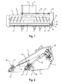
- FIG. 1 1 shows a cutting unit consisting of a cutting table 2 and a cutting trough 3.
- dividing plane 4 illustrates the cutting table is structurally separate from the cutting trough 3, so that it can be adjusted relative to this in the direction of harvesting or in the opposite direction.
- the cutting table 2 receives a mowing blade 5, which consists of a knife bar, not shown, and a plurality of knife blades 6 mounted thereon. In this case, the mower blade 5 is guided in fingers 7, which are fixed to the cutting table 2.
- a knife gear 8 is arranged at the end of the mowing blade 5, wherein this blade gear 8 has a housing 8a and drives the mowing blade 5 by means of a crank pin 9.
- the cutting trough 3 receives a transverse conveyor 10, which is provided with counter-rotating worm threads 11 and 12, so that the crop cut by the mowing blade 5 in cooperation with the fingers 7 centered the cutting trough 3 is merged. From there, the crop is transferred to a feeder 13 which then feeds it to a processing device, not shown, such as a threshing and separating device of a combine harvester or a chopper of a forage harvester.
- the entire cutting 1 is preferably connected by a coupling device, not shown, with the inclined conveyor 13, so that it can be exchanged for another header and also can be transported for a road trip of the harvester behind this on a trailer.
- the drive of the cutting unit 1 is carried out by a arranged in the inclined conveyor 13 shaft 14 from a propeller shaft 15 on a gear assembly 16.
- This gear assembly 16 drives on the one hand the knife gear 8 and on the other the transverse conveyor 10 and a reel, not shown.
- To drive the knife gear 8 is how of the FIG. 1 can be removed from the gear assembly 16, an output shaft 17 which is connected to a propeller shaft 18, said propeller shaft 18 is connected at its other end drivingly connected to an input shaft 19 of the knife gear 7.
- a pot-shaped flywheel 19a for reducing the resulting from the Exzentertrieb of the knife gear 8 and from the reciprocating mass of the mower blade resulting mass forces.
- This design of the flywheel 19a also allows an extension of the propeller shaft 18, resulting in an increase in the displacement path.
- FIG. 2 A corresponding to the schematic representation of FIG. 1 trained cutting unit 1 is partially in the FIG. 2 shown.
- dashed lines while a position of the cutting table 2 is shown, in which this is adjusted relative to the cutting unit 3 in the longitudinal direction.
- the propeller shaft 18 is adjusted in this dashed line position of the knife gear 8 in its maximum longitudinal extent. In contrast, it is adjusted in the retracted position of the cutting table 2 in its minimum longitudinal extent.
- the arrangement of the knife gear 8 on the cutting table 2 and the gear assembly 16 to the cutting unit 3 is essentially given by the fact that on the one hand of the knife gear 8, the oscillating motion must be transmitted to the mower blade 5, and the other in that of the shaft 14 via the cardan shaft 15, the gear assembly 16 must be driven. This results in a certain distance of the knife gear 8 to the gear assembly 16, whereby substantially the length of the propeller shaft 18 is determined.
- a device must be provided in the drive of the mowing blade 5, which shuts off the drive due to the exceeding of a maximum torque upon impact of the mowing blade 5 on stones, metal parts, etc.
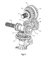
- the gear drive of the gear assembly 16 is shown.
- This has a transmission input shaft 20 with a drive bevel gear 21 arranged thereon.
- the drive bevel gear 21 is engaged with a first driven bevel gear 22 which is arranged on a shaft 23 leading to the transverse conveyor 9.
- the first driven bevel gear 21 also has a meshing engagement with a second Output bevel gear 24 which is disposed on an intermediate shaft 25 and drives a drive wheel 26 of a spur gear 27 via this.
- one of the spur gear 27 is a driven wheel 28, which already in connection with the FIG. 1 explained output shaft 17 via an overload clutch 29 drives.
- Part of this overload clutch 29 is a package disc springs 30th
- the overload clutch 29 receiving output to the propeller shaft 16 relative to the transmission input shaft 18 in harvest direction of the cutting unit 1 to the rear, so that there is a relatively large distance between the gear assembly 16 and the blade gear 8, whereby the displacement of the propeller shaft 18 is increased.
- the overload clutch 29 is integrated in the transmission assembly 16.
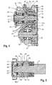
- the output gear 26 is rotatably mounted on a rotatably mounted on the output shaft 17 hollow shaft 32.
- This hollow shaft 32 together with a flange 33, a hub 34.
- a likewise flange-shaped driver 35 is arranged on the output shaft 17, which is rotatably on a driving profile 36 but axially displaceably guided on the output shaft 17.
- the hub 34 has an end face 37, in which offset by 180 ° to each other three recesses 38 are provided.
- This end face 37 of the hub 34 opposite an end face 39 of the driver 35 is arranged, which also has three mutually offset by 180 ° recesses 40. Between these end faces 37 and 39 are latching body 41 and 41 a, which engage in the recesses 38 and 40 and are guided in an annular cage 41 b.
- FIG. 4 It can also be seen that there are two detent bodies 41 on an outer radius and only one detent body 41a on an inner radius. It can also be seen from the illustration that the driver 35 is biased towards the hub 34 under the bias of the package of Belleville springs 30. In addition, an output flange 42 is arranged on the output shaft 17, via which the propeller shaft 18 can be driven. Finally, it is apparent from the illustration that on the driver 35, a trigger wheel 43 is attached, which with a sensor 44th interacts. In this way, disturbances in the drive of the knife gear 8, which occur when the overload clutch 29 is triggered, are signaled to the driver in a driver's cab of the harvesting machine.
- FIG. 5 An alternative embodiment and arrangement of an overload clutch 45 goes out of the FIG. 5 out. It is contrary to the FIG. 4 no hollow shaft provided, but the output shaft 17 is preferably driven directly via a spur gear, not shown.
- a hub 46 is provided with a Abtriebsflansch 47, while a fixed on the output shaft 17 thrust ring 48 forms a raceway for a Axialnadellager 49. Consequently, the hub 46 is freely rotatable, but supported in the axial direction, on the output shaft 17 at this stop ring 48.
- a driver 50 is longitudinally displaceable via a driving profile 51, but rotatably disposed on the output shaft 17. Furthermore, as already after FIG. 4 provided between the end faces 52 and 53 in recesses 54 and 55 corresponding latching body 56 and 56 a arranged. From the FIG. 5 shows that these locking body 56 and 56 a, which are formed as locking balls, are guided in an annular cage 57.
Landscapes
- Life Sciences & Earth Sciences (AREA)
- Environmental Sciences (AREA)
- Harvester Elements (AREA)
Applications Claiming Priority (1)
| Application Number | Priority Date | Filing Date | Title |
|---|---|---|---|
| DE102012107682.0A DE102012107682A1 (de) | 2012-08-21 | 2012-08-21 | Schneidwerk für eine selbstfahrende Erntemaschine |
Publications (3)
| Publication Number | Publication Date |
|---|---|
| EP2700294A2 true EP2700294A2 (fr) | 2014-02-26 |
| EP2700294A3 EP2700294A3 (fr) | 2015-09-30 |
| EP2700294B1 EP2700294B1 (fr) | 2017-10-18 |
Family
ID=48520722
Family Applications (1)
| Application Number | Title | Priority Date | Filing Date |
|---|---|---|---|
| EP13168844.2A Active EP2700294B1 (fr) | 2012-08-21 | 2013-05-23 | Barre de coupe pour une moissonneuse automobile |
Country Status (4)
| Country | Link |
|---|---|
| EP (1) | EP2700294B1 (fr) |
| DE (1) | DE102012107682A1 (fr) |
| RU (1) | RU2626946C2 (fr) |
| UA (1) | UA115422C2 (fr) |
Cited By (5)
| Publication number | Priority date | Publication date | Assignee | Title |
|---|---|---|---|---|
| EP3269222A1 (fr) * | 2016-07-12 | 2018-01-17 | Deere & Company | Dispositif d'entraînement d'une barre de coupe d'un outil de coupe |
| EP3571916A2 (fr) | 2018-05-24 | 2019-11-27 | Deere & Company | Dispositif d'entraînement d'un faisceau de barre de coupe d'un outil de coupe |
| CN113606293A (zh) * | 2021-08-11 | 2021-11-05 | 中国铁建重工集团股份有限公司 | 一种青贮收获机及青贮收获机割台过载保护装置 |
| EP4215036A1 (fr) | 2022-01-20 | 2023-07-26 | CNH Industrial Belgium N.V. | Transmission pour lames à mouvement alternatif d'un bec cueilleur de moissonneuse |
| EP4388851A1 (fr) | 2022-12-21 | 2024-06-26 | CNH Industrial Belgium N.V. | Chaîne cinématique pour couteaux à mouvement alternatif d'une tête de coupe agricole |
Families Citing this family (2)
| Publication number | Priority date | Publication date | Assignee | Title |
|---|---|---|---|---|
| CN105917981B (zh) * | 2016-06-28 | 2021-10-22 | 东莞市嘉航实业有限公司 | 环割机 |
| DE102022131080A1 (de) | 2022-11-24 | 2024-05-29 | Robert Bosch Gesellschaft mit beschränkter Haftung | Momentenkopplungsvorrichtung zur Kopplung von Antriebsrädern zweier Fahrzeuge, Verfahren zum Bereitstellen eines Rekuperationsmodus eines ersten Elektrofahrzeugs sowie Verfahren zum Bereitstellen eines Auflademodus eines zweiten Elektrofahrzeugs |
Citations (2)
| Publication number | Priority date | Publication date | Assignee | Title |
|---|---|---|---|---|
| DE1260844B (de) | 1967-03-01 | 1968-02-08 | Busatis Geb | UEberlasteinrichtungen fuer Maehmesserantriebe |
| EP2364584A2 (fr) | 2010-03-11 | 2011-09-14 | CLAAS Selbstfahrende Erntemaschinen GmbH | Barre de coupe pour une moissonneuse |
Family Cites Families (5)
| Publication number | Priority date | Publication date | Assignee | Title |
|---|---|---|---|---|
| SU512733A1 (ru) * | 1973-08-28 | 1976-05-05 | Головное Специализированное Конструкторское Бюро По Машинам Для Уборки Зерновых Культур И Самоходным Шасси | Валкова жатка |
| US4011709A (en) * | 1974-11-13 | 1977-03-15 | Deere & Company | Harvesting platform |
| AT393342B (de) * | 1981-03-05 | 1991-09-25 | Bauer & Co Gmbh Reform Werke | Frontmaehwerk |
| DE20108221U1 (de) * | 2001-05-16 | 2001-08-16 | Wilhelm Stoll Maschinenfabrik Gmbh, 38268 Lengede | Antrieb mit Überlastkupplung für eine landwirtschaftliche Maschine |
| RU51818U1 (ru) * | 2005-06-06 | 2006-03-10 | Илья Алексеевич Шитый | Косилка роторная |
-
2012
- 2012-08-21 DE DE102012107682.0A patent/DE102012107682A1/de not_active Withdrawn
-
2013
- 2013-05-23 EP EP13168844.2A patent/EP2700294B1/fr active Active
- 2013-08-07 UA UAA201309830A patent/UA115422C2/uk unknown
- 2013-08-19 RU RU2013138314A patent/RU2626946C2/ru active
Patent Citations (2)
| Publication number | Priority date | Publication date | Assignee | Title |
|---|---|---|---|---|
| DE1260844B (de) | 1967-03-01 | 1968-02-08 | Busatis Geb | UEberlasteinrichtungen fuer Maehmesserantriebe |
| EP2364584A2 (fr) | 2010-03-11 | 2011-09-14 | CLAAS Selbstfahrende Erntemaschinen GmbH | Barre de coupe pour une moissonneuse |
Cited By (9)
| Publication number | Priority date | Publication date | Assignee | Title |
|---|---|---|---|---|
| EP3269222A1 (fr) * | 2016-07-12 | 2018-01-17 | Deere & Company | Dispositif d'entraînement d'une barre de coupe d'un outil de coupe |
| DE102016212646A1 (de) | 2016-07-12 | 2018-01-18 | Deere & Company | Antriebsanordnung zum Antrieb eines Mähwerksbalkens eines Schneidwerks |
| US10356976B2 (en) | 2016-07-12 | 2019-07-23 | Deere & Company | Drive arrangement for driving a cutter bar of a cutting mechanism |
| EP3571916A2 (fr) | 2018-05-24 | 2019-11-27 | Deere & Company | Dispositif d'entraînement d'un faisceau de barre de coupe d'un outil de coupe |
| US11160209B2 (en) | 2018-05-24 | 2021-11-02 | Deere & Company | Hydraulic drive arrangement to drive a reciprocating cutter bar |
| CN113606293A (zh) * | 2021-08-11 | 2021-11-05 | 中国铁建重工集团股份有限公司 | 一种青贮收获机及青贮收获机割台过载保护装置 |
| EP4215036A1 (fr) | 2022-01-20 | 2023-07-26 | CNH Industrial Belgium N.V. | Transmission pour lames à mouvement alternatif d'un bec cueilleur de moissonneuse |
| US12550815B2 (en) | 2022-01-20 | 2026-02-17 | Cnh Industrial America Llc | Driveline for the reciprocating knives of a combine header |
| EP4388851A1 (fr) | 2022-12-21 | 2024-06-26 | CNH Industrial Belgium N.V. | Chaîne cinématique pour couteaux à mouvement alternatif d'une tête de coupe agricole |
Also Published As
| Publication number | Publication date |
|---|---|
| RU2626946C2 (ru) | 2017-08-02 |
| DE102012107682A1 (de) | 2014-03-20 |
| EP2700294B1 (fr) | 2017-10-18 |
| UA115422C2 (uk) | 2017-11-10 |
| EP2700294A3 (fr) | 2015-09-30 |
| RU2013138314A (ru) | 2015-02-27 |
Similar Documents
| Publication | Publication Date | Title |
|---|---|---|
| EP2700294B1 (fr) | Barre de coupe pour une moissonneuse automobile | |
| EP1402768B1 (fr) | Dispositif de détection pour détecter un bourrage dans une machine de récolte | |
| BE1023764B1 (de) | Feldhäcksler mit reversierbarer konditioniereinrichtung | |
| DE102004029953A1 (de) | Erntevorsatzantrieb | |
| EP2687079A2 (fr) | Appareil frontal fonctionnant indépendamment des rangées destiné à récolter des produits de récolte à tiges | |
| EP3179844B1 (fr) | Récolteuse automotrice | |
| BE1024973B1 (de) | Antriebsanordnung zum drehzahlveränderbaren Antrieb einer mit zwei Konditionierwalzen ausgestatteten Konditioniereinrichtung eines Feldhäckslers | |
| DE19950748A1 (de) | Mähgerät | |
| EP1864567B1 (fr) | Ramasseur | |
| EP2145531B1 (fr) | Agencement d'une liaison, notamment entre un cylindre d'alimentation et l'entraînement d'une récolteuse-hacheuse | |
| BE1024945A1 (de) | Häckseltrommel für einen Feldhäcksler mit in eine Außerbetriebsstellung verstellbaren Messerhaltern | |
| EP2700293B1 (fr) | Engrenage pour l'entraînement d'une lame de coupe d'une moissonneuse | |
| DE102015103921A1 (de) | Riementriebsystem | |
| EP1738634B1 (fr) | Dispositif de ramassage de produits de récolte ainsi que machine de récolte. | |
| EP2756747A2 (fr) | Appareil frontal pour la récolte de maïs | |
| EP1932415B1 (fr) | Dispositif muni d'une première et d'une seconde unité de travail | |
| DE69617611T2 (de) | Heuwerbungsmaschine | |
| EP4710749A1 (fr) | Agencement d'entraînement pour entraîner une tête de récolte par une récolteuse-hacheuse | |
| EP0858732A1 (fr) | Machine de récolte munie de moyens de compensation pour le travail sur une pente | |
| DD296396A5 (de) | Maehdrescher mit einem dreschwerk | |
| EP3090616B1 (fr) | Reglage d'angle de coupe d'une barre de coupe | |
| EP3704927B1 (fr) | Barre de coupe pour machine de récolte agricole | |
| EP3639649B1 (fr) | Système pour entraînement à changement de vitesse de rotation d'un agencement de conditionnement équipé de deux rouleaux de conditionnement d'une ramasseuse-hacheuse | |
| DE102009028055B4 (de) | Selbstfahrende Erntemaschine | |
| EP1932417A1 (fr) | Dispositif de saisie de récolte au sol |
Legal Events
| Date | Code | Title | Description |
|---|---|---|---|
| PUAI | Public reference made under article 153(3) epc to a published international application that has entered the european phase |
Free format text: ORIGINAL CODE: 0009012 |
|
| AK | Designated contracting states |
Kind code of ref document: A2 Designated state(s): AL AT BE BG CH CY CZ DE DK EE ES FI FR GB GR HR HU IE IS IT LI LT LU LV MC MK MT NL NO PL PT RO RS SE SI SK SM TR |
|
| AX | Request for extension of the european patent |
Extension state: BA ME |
|
| PUAL | Search report despatched |
Free format text: ORIGINAL CODE: 0009013 |
|
| AK | Designated contracting states |
Kind code of ref document: A3 Designated state(s): AL AT BE BG CH CY CZ DE DK EE ES FI FR GB GR HR HU IE IS IT LI LT LU LV MC MK MT NL NO PL PT RO RS SE SI SK SM TR |
|
| AX | Request for extension of the european patent |
Extension state: BA ME |
|
| RIC1 | Information provided on ipc code assigned before grant |
Ipc: A01D 34/30 20060101AFI20150827BHEP |
|
| 17P | Request for examination filed |
Effective date: 20160330 |
|
| RBV | Designated contracting states (corrected) |
Designated state(s): AL AT BE BG CH CY CZ DE DK EE ES FI FR GB GR HR HU IE IS IT LI LT LU LV MC MK MT NL NO PL PT RO RS SE SI SK SM TR |
|
| RAP1 | Party data changed (applicant data changed or rights of an application transferred) |
Owner name: CLAAS SELBSTFAHRENDE ERNTEMASCHINEN GMBH |
|
| GRAP | Despatch of communication of intention to grant a patent |
Free format text: ORIGINAL CODE: EPIDOSNIGR1 |
|
| INTG | Intention to grant announced |
Effective date: 20170704 |
|
| GRAS | Grant fee paid |
Free format text: ORIGINAL CODE: EPIDOSNIGR3 |
|
| GRAA | (expected) grant |
Free format text: ORIGINAL CODE: 0009210 |
|
| AK | Designated contracting states |
Kind code of ref document: B1 Designated state(s): AL AT BE BG CH CY CZ DE DK EE ES FI FR GB GR HR HU IE IS IT LI LT LU LV MC MK MT NL NO PL PT RO RS SE SI SK SM TR |
|
| REG | Reference to a national code |
Ref country code: GB Ref legal event code: FG4D Free format text: NOT ENGLISH |
|
| REG | Reference to a national code |
Ref country code: CH Ref legal event code: EP |
|
| REG | Reference to a national code |
Ref country code: AT Ref legal event code: REF Ref document number: 937124 Country of ref document: AT Kind code of ref document: T Effective date: 20171115 Ref country code: IE Ref legal event code: FG4D Free format text: LANGUAGE OF EP DOCUMENT: GERMAN |
|
| REG | Reference to a national code |
Ref country code: DE Ref legal event code: R096 Ref document number: 502013008578 Country of ref document: DE |
|
| REG | Reference to a national code |
Ref country code: NL Ref legal event code: MP Effective date: 20171018 |
|
| REG | Reference to a national code |
Ref country code: LT Ref legal event code: MG4D |
|
| PG25 | Lapsed in a contracting state [announced via postgrant information from national office to epo] |
Ref country code: NL Free format text: LAPSE BECAUSE OF FAILURE TO SUBMIT A TRANSLATION OF THE DESCRIPTION OR TO PAY THE FEE WITHIN THE PRESCRIBED TIME-LIMIT Effective date: 20171018 |
|
| PG25 | Lapsed in a contracting state [announced via postgrant information from national office to epo] |
Ref country code: SE Free format text: LAPSE BECAUSE OF FAILURE TO SUBMIT A TRANSLATION OF THE DESCRIPTION OR TO PAY THE FEE WITHIN THE PRESCRIBED TIME-LIMIT Effective date: 20171018 Ref country code: LT Free format text: LAPSE BECAUSE OF FAILURE TO SUBMIT A TRANSLATION OF THE DESCRIPTION OR TO PAY THE FEE WITHIN THE PRESCRIBED TIME-LIMIT Effective date: 20171018 Ref country code: NO Free format text: LAPSE BECAUSE OF FAILURE TO SUBMIT A TRANSLATION OF THE DESCRIPTION OR TO PAY THE FEE WITHIN THE PRESCRIBED TIME-LIMIT Effective date: 20180118 Ref country code: FI Free format text: LAPSE BECAUSE OF FAILURE TO SUBMIT A TRANSLATION OF THE DESCRIPTION OR TO PAY THE FEE WITHIN THE PRESCRIBED TIME-LIMIT Effective date: 20171018 Ref country code: ES Free format text: LAPSE BECAUSE OF FAILURE TO SUBMIT A TRANSLATION OF THE DESCRIPTION OR TO PAY THE FEE WITHIN THE PRESCRIBED TIME-LIMIT Effective date: 20171018 |
|
| PG25 | Lapsed in a contracting state [announced via postgrant information from national office to epo] |
Ref country code: LV Free format text: LAPSE BECAUSE OF FAILURE TO SUBMIT A TRANSLATION OF THE DESCRIPTION OR TO PAY THE FEE WITHIN THE PRESCRIBED TIME-LIMIT Effective date: 20171018 Ref country code: GR Free format text: LAPSE BECAUSE OF FAILURE TO SUBMIT A TRANSLATION OF THE DESCRIPTION OR TO PAY THE FEE WITHIN THE PRESCRIBED TIME-LIMIT Effective date: 20180119 Ref country code: HR Free format text: LAPSE BECAUSE OF FAILURE TO SUBMIT A TRANSLATION OF THE DESCRIPTION OR TO PAY THE FEE WITHIN THE PRESCRIBED TIME-LIMIT Effective date: 20171018 Ref country code: IS Free format text: LAPSE BECAUSE OF FAILURE TO SUBMIT A TRANSLATION OF THE DESCRIPTION OR TO PAY THE FEE WITHIN THE PRESCRIBED TIME-LIMIT Effective date: 20180218 Ref country code: BG Free format text: LAPSE BECAUSE OF FAILURE TO SUBMIT A TRANSLATION OF THE DESCRIPTION OR TO PAY THE FEE WITHIN THE PRESCRIBED TIME-LIMIT Effective date: 20180118 Ref country code: RS Free format text: LAPSE BECAUSE OF FAILURE TO SUBMIT A TRANSLATION OF THE DESCRIPTION OR TO PAY THE FEE WITHIN THE PRESCRIBED TIME-LIMIT Effective date: 20171018 |
|
| REG | Reference to a national code |
Ref country code: DE Ref legal event code: R097 Ref document number: 502013008578 Country of ref document: DE |
|
| PG25 | Lapsed in a contracting state [announced via postgrant information from national office to epo] |
Ref country code: EE Free format text: LAPSE BECAUSE OF FAILURE TO SUBMIT A TRANSLATION OF THE DESCRIPTION OR TO PAY THE FEE WITHIN THE PRESCRIBED TIME-LIMIT Effective date: 20171018 Ref country code: CZ Free format text: LAPSE BECAUSE OF FAILURE TO SUBMIT A TRANSLATION OF THE DESCRIPTION OR TO PAY THE FEE WITHIN THE PRESCRIBED TIME-LIMIT Effective date: 20171018 Ref country code: SK Free format text: LAPSE BECAUSE OF FAILURE TO SUBMIT A TRANSLATION OF THE DESCRIPTION OR TO PAY THE FEE WITHIN THE PRESCRIBED TIME-LIMIT Effective date: 20171018 Ref country code: DK Free format text: LAPSE BECAUSE OF FAILURE TO SUBMIT A TRANSLATION OF THE DESCRIPTION OR TO PAY THE FEE WITHIN THE PRESCRIBED TIME-LIMIT Effective date: 20171018 |
|
| PLBE | No opposition filed within time limit |
Free format text: ORIGINAL CODE: 0009261 |
|
| STAA | Information on the status of an ep patent application or granted ep patent |
Free format text: STATUS: NO OPPOSITION FILED WITHIN TIME LIMIT |
|
| PG25 | Lapsed in a contracting state [announced via postgrant information from national office to epo] |
Ref country code: PL Free format text: LAPSE BECAUSE OF FAILURE TO SUBMIT A TRANSLATION OF THE DESCRIPTION OR TO PAY THE FEE WITHIN THE PRESCRIBED TIME-LIMIT Effective date: 20171018 Ref country code: SM Free format text: LAPSE BECAUSE OF FAILURE TO SUBMIT A TRANSLATION OF THE DESCRIPTION OR TO PAY THE FEE WITHIN THE PRESCRIBED TIME-LIMIT Effective date: 20171018 Ref country code: RO Free format text: LAPSE BECAUSE OF FAILURE TO SUBMIT A TRANSLATION OF THE DESCRIPTION OR TO PAY THE FEE WITHIN THE PRESCRIBED TIME-LIMIT Effective date: 20171018 Ref country code: IT Free format text: LAPSE BECAUSE OF FAILURE TO SUBMIT A TRANSLATION OF THE DESCRIPTION OR TO PAY THE FEE WITHIN THE PRESCRIBED TIME-LIMIT Effective date: 20171018 |
|
| 26N | No opposition filed |
Effective date: 20180719 |
|
| PG25 | Lapsed in a contracting state [announced via postgrant information from national office to epo] |
Ref country code: MT Free format text: LAPSE BECAUSE OF FAILURE TO SUBMIT A TRANSLATION OF THE DESCRIPTION OR TO PAY THE FEE WITHIN THE PRESCRIBED TIME-LIMIT Effective date: 20171018 |
|
| PG25 | Lapsed in a contracting state [announced via postgrant information from national office to epo] |
Ref country code: SI Free format text: LAPSE BECAUSE OF FAILURE TO SUBMIT A TRANSLATION OF THE DESCRIPTION OR TO PAY THE FEE WITHIN THE PRESCRIBED TIME-LIMIT Effective date: 20171018 |
|
| REG | Reference to a national code |
Ref country code: CH Ref legal event code: PL |
|
| GBPC | Gb: european patent ceased through non-payment of renewal fee |
Effective date: 20180523 |
|
| PG25 | Lapsed in a contracting state [announced via postgrant information from national office to epo] |
Ref country code: MC Free format text: LAPSE BECAUSE OF FAILURE TO SUBMIT A TRANSLATION OF THE DESCRIPTION OR TO PAY THE FEE WITHIN THE PRESCRIBED TIME-LIMIT Effective date: 20171018 |
|
| REG | Reference to a national code |
Ref country code: IE Ref legal event code: MM4A |
|
| PG25 | Lapsed in a contracting state [announced via postgrant information from national office to epo] |
Ref country code: CH Free format text: LAPSE BECAUSE OF NON-PAYMENT OF DUE FEES Effective date: 20180531 Ref country code: LI Free format text: LAPSE BECAUSE OF NON-PAYMENT OF DUE FEES Effective date: 20180531 |
|
| PG25 | Lapsed in a contracting state [announced via postgrant information from national office to epo] |
Ref country code: LU Free format text: LAPSE BECAUSE OF NON-PAYMENT OF DUE FEES Effective date: 20180523 |
|
| PG25 | Lapsed in a contracting state [announced via postgrant information from national office to epo] |
Ref country code: FR Free format text: LAPSE BECAUSE OF NON-PAYMENT OF DUE FEES Effective date: 20180531 Ref country code: IE Free format text: LAPSE BECAUSE OF NON-PAYMENT OF DUE FEES Effective date: 20180523 Ref country code: GB Free format text: LAPSE BECAUSE OF NON-PAYMENT OF DUE FEES Effective date: 20180523 |
|
| REG | Reference to a national code |
Ref country code: AT Ref legal event code: MM01 Ref document number: 937124 Country of ref document: AT Kind code of ref document: T Effective date: 20180523 |
|
| PG25 | Lapsed in a contracting state [announced via postgrant information from national office to epo] |
Ref country code: AT Free format text: LAPSE BECAUSE OF NON-PAYMENT OF DUE FEES Effective date: 20180523 |
|
| PG25 | Lapsed in a contracting state [announced via postgrant information from national office to epo] |
Ref country code: TR Free format text: LAPSE BECAUSE OF FAILURE TO SUBMIT A TRANSLATION OF THE DESCRIPTION OR TO PAY THE FEE WITHIN THE PRESCRIBED TIME-LIMIT Effective date: 20171018 |
|
| PG25 | Lapsed in a contracting state [announced via postgrant information from national office to epo] |
Ref country code: HU Free format text: LAPSE BECAUSE OF FAILURE TO SUBMIT A TRANSLATION OF THE DESCRIPTION OR TO PAY THE FEE WITHIN THE PRESCRIBED TIME-LIMIT; INVALID AB INITIO Effective date: 20130523 Ref country code: PT Free format text: LAPSE BECAUSE OF FAILURE TO SUBMIT A TRANSLATION OF THE DESCRIPTION OR TO PAY THE FEE WITHIN THE PRESCRIBED TIME-LIMIT Effective date: 20171018 |
|
| PG25 | Lapsed in a contracting state [announced via postgrant information from national office to epo] |
Ref country code: CY Free format text: LAPSE BECAUSE OF FAILURE TO SUBMIT A TRANSLATION OF THE DESCRIPTION OR TO PAY THE FEE WITHIN THE PRESCRIBED TIME-LIMIT Effective date: 20171018 Ref country code: MK Free format text: LAPSE BECAUSE OF NON-PAYMENT OF DUE FEES Effective date: 20171018 |
|
| PG25 | Lapsed in a contracting state [announced via postgrant information from national office to epo] |
Ref country code: AL Free format text: LAPSE BECAUSE OF FAILURE TO SUBMIT A TRANSLATION OF THE DESCRIPTION OR TO PAY THE FEE WITHIN THE PRESCRIBED TIME-LIMIT Effective date: 20171018 |
|
| P01 | Opt-out of the competence of the unified patent court (upc) registered |
Effective date: 20230515 |
|
| PGFP | Annual fee paid to national office [announced via postgrant information from national office to epo] |
Ref country code: DE Payment date: 20250521 Year of fee payment: 13 |
|
| PGFP | Annual fee paid to national office [announced via postgrant information from national office to epo] |
Ref country code: BE Payment date: 20250521 Year of fee payment: 13 |