EP2700332A2 - Appareil d'hygiène buccale, en particulier brosse à dents - Google Patents
Appareil d'hygiène buccale, en particulier brosse à dents Download PDFInfo
- Publication number
- EP2700332A2 EP2700332A2 EP13005479.4A EP13005479A EP2700332A2 EP 2700332 A2 EP2700332 A2 EP 2700332A2 EP 13005479 A EP13005479 A EP 13005479A EP 2700332 A2 EP2700332 A2 EP 2700332A2
- Authority
- EP
- European Patent Office
- Prior art keywords
- snap
- oral hygiene
- device body
- disc
- hygiene device
- Prior art date
- Legal status (The legal status is an assumption and is not a legal conclusion. Google has not performed a legal analysis and makes no representation as to the accuracy of the status listed.)
- Withdrawn
Links
- 238000005452 bending Methods 0.000 claims abstract description 32
- 238000003825 pressing Methods 0.000 claims abstract description 32
- 238000000034 method Methods 0.000 abstract description 73
- 238000004519 manufacturing process Methods 0.000 abstract description 29
- 238000001746 injection moulding Methods 0.000 description 50
- 230000008569 process Effects 0.000 description 38
- 238000003466 welding Methods 0.000 description 36
- 230000006870 function Effects 0.000 description 23
- 238000012360 testing method Methods 0.000 description 20
- 239000000463 material Substances 0.000 description 17
- 238000013461 design Methods 0.000 description 15
- -1 Polypropylen Polymers 0.000 description 13
- 230000007246 mechanism Effects 0.000 description 13
- 238000004806 packaging method and process Methods 0.000 description 12
- 239000000047 product Substances 0.000 description 12
- 239000011324 bead Substances 0.000 description 11
- 229920003023 plastic Polymers 0.000 description 11
- 239000004033 plastic Substances 0.000 description 11
- 239000004952 Polyamide Substances 0.000 description 10
- 229920002647 polyamide Polymers 0.000 description 10
- 238000007789 sealing Methods 0.000 description 10
- 230000008859 change Effects 0.000 description 9
- 238000010586 diagram Methods 0.000 description 9
- 229910000639 Spring steel Inorganic materials 0.000 description 8
- 230000035882 stress Effects 0.000 description 8
- 229920000573 polyethylene Polymers 0.000 description 7
- 229920001155 polypropylene Polymers 0.000 description 7
- 238000002347 injection Methods 0.000 description 6
- 239000007924 injection Substances 0.000 description 6
- 230000001960 triggered effect Effects 0.000 description 6
- 238000004140 cleaning Methods 0.000 description 5
- 230000010354 integration Effects 0.000 description 5
- 238000005555 metalworking Methods 0.000 description 5
- 239000007779 soft material Substances 0.000 description 5
- 210000003813 thumb Anatomy 0.000 description 5
- PPBRXRYQALVLMV-UHFFFAOYSA-N Styrene Chemical compound C=CC1=CC=CC=C1 PPBRXRYQALVLMV-UHFFFAOYSA-N 0.000 description 4
- 230000008901 benefit Effects 0.000 description 4
- 229920001971 elastomer Polymers 0.000 description 4
- 239000000806 elastomer Substances 0.000 description 4
- 229920001903 high density polyethylene Polymers 0.000 description 4
- 230000009191 jumping Effects 0.000 description 4
- 239000002184 metal Substances 0.000 description 4
- 229910052751 metal Inorganic materials 0.000 description 4
- 229920003229 poly(methyl methacrylate) Polymers 0.000 description 4
- 229920006324 polyoxymethylene Polymers 0.000 description 4
- 229920002635 polyurethane Polymers 0.000 description 4
- 239000004814 polyurethane Substances 0.000 description 4
- 229920000623 Cellulose acetate phthalate Polymers 0.000 description 3
- DQEFEBPAPFSJLV-UHFFFAOYSA-N Cellulose propionate Chemical compound CCC(=O)OCC1OC(OC(=O)CC)C(OC(=O)CC)C(OC(=O)CC)C1OC1C(OC(=O)CC)C(OC(=O)CC)C(OC(=O)CC)C(COC(=O)CC)O1 DQEFEBPAPFSJLV-UHFFFAOYSA-N 0.000 description 3
- 229920002301 cellulose acetate Polymers 0.000 description 3
- 229940081734 cellulose acetate phthalate Drugs 0.000 description 3
- 229920001727 cellulose butyrate Polymers 0.000 description 3
- 229920006218 cellulose propionate Polymers 0.000 description 3
- 229920001577 copolymer Polymers 0.000 description 3
- 230000006378 damage Effects 0.000 description 3
- 230000000694 effects Effects 0.000 description 3
- 238000004049 embossing Methods 0.000 description 3
- 235000019589 hardness Nutrition 0.000 description 3
- 230000002093 peripheral effect Effects 0.000 description 3
- 229920000515 polycarbonate Polymers 0.000 description 3
- 229920000139 polyethylene terephthalate Polymers 0.000 description 3
- 239000005020 polyethylene terephthalate Substances 0.000 description 3
- 238000004080 punching Methods 0.000 description 3
- 229920000468 styrene butadiene styrene block copolymer Polymers 0.000 description 3
- 229920001169 thermoplastic Polymers 0.000 description 3
- 229920002397 thermoplastic olefin Polymers 0.000 description 3
- 229920006346 thermoplastic polyester elastomer Polymers 0.000 description 3
- 239000004416 thermosoftening plastic Substances 0.000 description 3
- JDCCCHBBXRQRGU-UHFFFAOYSA-N 5-phenylpenta-2,4-dienenitrile Chemical compound N#CC=CC=CC1=CC=CC=C1 JDCCCHBBXRQRGU-UHFFFAOYSA-N 0.000 description 2
- LYCAIKOWRPUZTN-UHFFFAOYSA-N Ethylene glycol Chemical compound OCCO LYCAIKOWRPUZTN-UHFFFAOYSA-N 0.000 description 2
- PXHVJJICTQNCMI-UHFFFAOYSA-N Nickel Chemical compound [Ni] PXHVJJICTQNCMI-UHFFFAOYSA-N 0.000 description 2
- 239000004698 Polyethylene Substances 0.000 description 2
- 239000004743 Polypropylene Substances 0.000 description 2
- 208000027418 Wounds and injury Diseases 0.000 description 2
- 239000004676 acrylonitrile butadiene styrene Substances 0.000 description 2
- 230000009471 action Effects 0.000 description 2
- 238000004026 adhesive bonding Methods 0.000 description 2
- 229920002678 cellulose Polymers 0.000 description 2
- 239000001913 cellulose Substances 0.000 description 2
- 239000003795 chemical substances by application Substances 0.000 description 2
- 238000005260 corrosion Methods 0.000 description 2
- 230000007797 corrosion Effects 0.000 description 2
- 230000002950 deficient Effects 0.000 description 2
- 210000003811 finger Anatomy 0.000 description 2
- 208000014674 injury Diseases 0.000 description 2
- 238000003780 insertion Methods 0.000 description 2
- 230000037431 insertion Effects 0.000 description 2
- 238000012858 packaging process Methods 0.000 description 2
- 229920000728 polyester Polymers 0.000 description 2
- 229920000098 polyolefin Polymers 0.000 description 2
- 229920002223 polystyrene Polymers 0.000 description 2
- 229920000915 polyvinyl chloride Polymers 0.000 description 2
- 238000012545 processing Methods 0.000 description 2
- 230000000284 resting effect Effects 0.000 description 2
- 238000000926 separation method Methods 0.000 description 2
- 238000005476 soldering Methods 0.000 description 2
- 239000000243 solution Substances 0.000 description 2
- 229910001220 stainless steel Inorganic materials 0.000 description 2
- 239000010935 stainless steel Substances 0.000 description 2
- 229920000638 styrene acrylonitrile Polymers 0.000 description 2
- 239000011115 styrene butadiene Substances 0.000 description 2
- 229920002725 thermoplastic elastomer Polymers 0.000 description 2
- 238000009732 tufting Methods 0.000 description 2
- 235000010585 Ammi visnaga Nutrition 0.000 description 1
- 244000153158 Ammi visnaga Species 0.000 description 1
- 241000196324 Embryophyta Species 0.000 description 1
- 208000010201 Exanthema Diseases 0.000 description 1
- 241000628997 Flos Species 0.000 description 1
- 241001295925 Gegenes Species 0.000 description 1
- 229930040373 Paraformaldehyde Natural products 0.000 description 1
- 239000004793 Polystyrene Substances 0.000 description 1
- BQCADISMDOOEFD-UHFFFAOYSA-N Silver Chemical compound [Ag] BQCADISMDOOEFD-UHFFFAOYSA-N 0.000 description 1
- 229910000831 Steel Inorganic materials 0.000 description 1
- 229920007962 Styrene Methyl Methacrylate Polymers 0.000 description 1
- 239000002174 Styrene-butadiene Substances 0.000 description 1
- 239000004433 Thermoplastic polyurethane Substances 0.000 description 1
- ATJFFYVFTNAWJD-UHFFFAOYSA-N Tin Chemical compound [Sn] ATJFFYVFTNAWJD-UHFFFAOYSA-N 0.000 description 1
- XECAHXYUAAWDEL-UHFFFAOYSA-N acrylonitrile butadiene styrene Chemical compound C=CC=C.C=CC#N.C=CC1=CC=CC=C1 XECAHXYUAAWDEL-UHFFFAOYSA-N 0.000 description 1
- 229920000122 acrylonitrile butadiene styrene Polymers 0.000 description 1
- 230000004913 activation Effects 0.000 description 1
- 230000032683 aging Effects 0.000 description 1
- 238000013459 approach Methods 0.000 description 1
- 230000006399 behavior Effects 0.000 description 1
- 230000001680 brushing effect Effects 0.000 description 1
- 230000009172 bursting Effects 0.000 description 1
- FACXGONDLDSNOE-UHFFFAOYSA-N buta-1,3-diene;styrene Chemical compound C=CC=C.C=CC1=CC=CC=C1.C=CC1=CC=CC=C1 FACXGONDLDSNOE-UHFFFAOYSA-N 0.000 description 1
- MTAZNLWOLGHBHU-UHFFFAOYSA-N butadiene-styrene rubber Chemical compound C=CC=C.C=CC1=CC=CC=C1 MTAZNLWOLGHBHU-UHFFFAOYSA-N 0.000 description 1
- 239000007795 chemical reaction product Substances 0.000 description 1
- 150000001875 compounds Chemical class 0.000 description 1
- 238000011109 contamination Methods 0.000 description 1
- 238000001816 cooling Methods 0.000 description 1
- 239000002537 cosmetic Substances 0.000 description 1
- 238000005520 cutting process Methods 0.000 description 1
- 230000007423 decrease Effects 0.000 description 1
- 238000005538 encapsulation Methods 0.000 description 1
- 201000005884 exanthem Diseases 0.000 description 1
- 230000002349 favourable effect Effects 0.000 description 1
- 210000005224 forefinger Anatomy 0.000 description 1
- 238000011990 functional testing Methods 0.000 description 1
- PCHJSUWPFVWCPO-UHFFFAOYSA-N gold Chemical compound [Au] PCHJSUWPFVWCPO-UHFFFAOYSA-N 0.000 description 1
- 229910052737 gold Inorganic materials 0.000 description 1
- 239000010931 gold Substances 0.000 description 1
- 230000005484 gravity Effects 0.000 description 1
- 239000004700 high-density polyethylene Substances 0.000 description 1
- WGCNASOHLSPBMP-UHFFFAOYSA-N hydroxyacetaldehyde Natural products OCC=O WGCNASOHLSPBMP-UHFFFAOYSA-N 0.000 description 1
- 238000007373 indentation Methods 0.000 description 1
- 238000012432 intermediate storage Methods 0.000 description 1
- 229920001684 low density polyethylene Polymers 0.000 description 1
- 239000004702 low-density polyethylene Substances 0.000 description 1
- 229940127554 medical product Drugs 0.000 description 1
- 238000002844 melting Methods 0.000 description 1
- 230000008018 melting Effects 0.000 description 1
- 239000012528 membrane Substances 0.000 description 1
- ADFPJHOAARPYLP-UHFFFAOYSA-N methyl 2-methylprop-2-enoate;styrene Chemical compound COC(=O)C(C)=C.C=CC1=CC=CC=C1 ADFPJHOAARPYLP-UHFFFAOYSA-N 0.000 description 1
- 238000000465 moulding Methods 0.000 description 1
- 229910052759 nickel Inorganic materials 0.000 description 1
- 238000005192 partition Methods 0.000 description 1
- 229920001707 polybutylene terephthalate Polymers 0.000 description 1
- 239000004417 polycarbonate Substances 0.000 description 1
- 229920000642 polymer Polymers 0.000 description 1
- 239000004926 polymethyl methacrylate Substances 0.000 description 1
- 239000004800 polyvinyl chloride Substances 0.000 description 1
- 206010037844 rash Diseases 0.000 description 1
- 230000009467 reduction Effects 0.000 description 1
- 230000004044 response Effects 0.000 description 1
- 238000012552 review Methods 0.000 description 1
- 210000003296 saliva Anatomy 0.000 description 1
- 229910052709 silver Inorganic materials 0.000 description 1
- 239000004332 silver Substances 0.000 description 1
- 239000010959 steel Substances 0.000 description 1
- 239000011145 styrene acrylonitrile resin Substances 0.000 description 1
- 229920003048 styrene butadiene rubber Polymers 0.000 description 1
- 238000004381 surface treatment Methods 0.000 description 1
- 229920006345 thermoplastic polyamide Polymers 0.000 description 1
- 229920002803 thermoplastic polyurethane Polymers 0.000 description 1
- 229910052718 tin Inorganic materials 0.000 description 1
- 239000011135 tin Substances 0.000 description 1
- 210000005182 tip of the tongue Anatomy 0.000 description 1
- 239000000606 toothpaste Substances 0.000 description 1
- 229940034610 toothpaste Drugs 0.000 description 1
- 229910052721 tungsten Inorganic materials 0.000 description 1
- 238000002604 ultrasonography Methods 0.000 description 1
- XLYOFNOQVPJJNP-UHFFFAOYSA-N water Substances O XLYOFNOQVPJJNP-UHFFFAOYSA-N 0.000 description 1
Images








Classifications
-
- A—HUMAN NECESSITIES
- A46—BRUSHWARE
- A46B—BRUSHES
- A46B15/00—Other brushes; Brushes with additional arrangements
- A46B15/0002—Arrangements for enhancing monitoring or controlling the brushing process
-
- A—HUMAN NECESSITIES
- A46—BRUSHWARE
- A46B—BRUSHES
- A46B15/00—Other brushes; Brushes with additional arrangements
- A46B15/0002—Arrangements for enhancing monitoring or controlling the brushing process
- A46B15/0004—Arrangements for enhancing monitoring or controlling the brushing process with a controlling means
- A46B15/0012—Arrangements for enhancing monitoring or controlling the brushing process with a controlling means with a pressure controlling device
-
- A—HUMAN NECESSITIES
- A46—BRUSHWARE
- A46B—BRUSHES
- A46B15/00—Other brushes; Brushes with additional arrangements
- A46B15/0002—Arrangements for enhancing monitoring or controlling the brushing process
- A46B15/0038—Arrangements for enhancing monitoring or controlling the brushing process with signalling means
- A46B15/004—Arrangements for enhancing monitoring or controlling the brushing process with signalling means with an acoustic signalling means, e.g. noise
-
- A—HUMAN NECESSITIES
- A46—BRUSHWARE
- A46B—BRUSHES
- A46B5/00—Brush bodies; Handles integral with brushware
- A46B5/002—Brush bodies; Handles integral with brushware having articulations, joints or flexible portions
- A46B5/0054—Brush bodies; Handles integral with brushware having articulations, joints or flexible portions designed to allow relative positioning of the head to body
- A46B5/0062—Brush bodies; Handles integral with brushware having articulations, joints or flexible portions designed to allow relative positioning of the head to body being flexible or resilient during use
-
- A—HUMAN NECESSITIES
- A46—BRUSHWARE
- A46B—BRUSHES
- A46B5/00—Brush bodies; Handles integral with brushware
- A46B5/002—Brush bodies; Handles integral with brushware having articulations, joints or flexible portions
- A46B5/0054—Brush bodies; Handles integral with brushware having articulations, joints or flexible portions designed to allow relative positioning of the head to body
- A46B5/0062—Brush bodies; Handles integral with brushware having articulations, joints or flexible portions designed to allow relative positioning of the head to body being flexible or resilient during use
- A46B5/007—Inserts made of different material, e.g. springs, plates
-
- A—HUMAN NECESSITIES
- A46—BRUSHWARE
- A46B—BRUSHES
- A46B2200/00—Brushes characterized by their functions, uses or applications
- A46B2200/10—For human or animal care
- A46B2200/1066—Toothbrush for cleaning the teeth or dentures
Definitions
- the present invention relates to an oral hygiene device according to the preamble of patent claim 1.
- a trained as a toothbrush oral hygiene device of this kind is for example from the document DE 93 10 112.0 U1 known. It has a toothbrush body with a head part and a subsequent brush style, which is provided with a handle part. Between the head part and the handle part, the brush style on a snap disk, which is peripherally completely covered and held by the toothbrush body and their flat sides are exposed to the environment. If the pressure exerted on the head portion pressing force exceeds a limit, the disc snaps from its original position to produce a clicking sound to its working position. When the pressure force is reduced, the snap-action disc returns to its original position.
- the acoustic signal in the form of a clicking sound indicates to the user of the toothbrush if he increases the pressing force too much when cleaning the teeth and also shows him again if he reduces it to a favorable range.
- corrosion and hygiene problems can occur in the area of the snap-action disc.
- the snap action is associated with a sudden rash, which can be felt when touching the snap disc as painful.
- the overmoulding of metal parts such as for example, the said snap-action disc, cause due to the temperatures required in the injection molding process, changes in the microstructure or external shape. Depending on the characteristics of a change in characteristics, this can be equivalent to functional change. Such a change can also be caused by the forces acting in the injection molding processes.
- WO 2004/010822 A a toothbrush with an integrated into the handle jump element near the neck part.
- the jump element is formed by one or more parallel spring blades, which are bent about the longitudinal axis of the toothbrush.
- the spring blades are embedded in an elastically deformable plastic material. If a limit pressing force is exceeded, the spring force is reduced abruptly, so that the neck and head part of the toothbrush pivot strongly back and thereby the pressing force is reduced. The cleaning function is virtually impossible with too much pressure.
- the snap-action disc is arranged in a cavity which is closed off from the surroundings. This protects the usually made of metal snap disc from corrosion and contamination and prevents the possibly corroded snap disc can come into contact with the environment. Moreover, the snap-action disc in conjunction with saliva, toothpaste and water offers no hygiene problems. In addition, the cavity acts as a resonance chamber, so that the clicking sound amplified when jumping the snap disc and is very audible outside the cavity of the toothbrush. This is a significant advantage over the solutions with over-molded domes. Moreover, the snap-on encapsulation reduces the risk of injury to the user even in the event of improper use.
- the user of the oral hygiene device such as a manual or electric toothbrush or a tongue cleaner, is indicated by the audible warning that he is using the oral hygiene device with excessive pressure, for example against the teeth or the gums. He can continue to use the oral hygiene device, however, since it is essentially only a warning signal when jumping the snap disc and the associated delivery of the acoustic signal acts and thereby no significant change in the spring force occurs. If the user reduces the pressure force to a value below a predetermined limit pressure force, the snap-action disc springs back and likewise emits an acoustic warning signal. The user recognizes that he is using the oral hygiene device again with a permissible pressure force. The acoustic warning signals the user also a learning effect is achieved, so that the oral hygiene device is consistently used over time with optimum contact pressure and the damage, such as teeth and gums, is reduced.
- the snap-action disc can be designed so that the warning signal sounds at the reset at substantially the same limit pressing force A G as when triggered.
- the limit pressing force A G is set lower for the warning signal during the reset than when triggered, so that the user, for example, practically relieve the toothbrush, and thus consciously determines that he has used too much pressure. This enhances the learning effect.
- the cavity and thus the snap-action disc is located between the head part and a handle part of the device body.
- Vorzugsswiese it is located approximately in the middle between the headboard and handle.
- the snap disc with its end portions facing the head part or facing away from this, attached to the device body or between the support member and the device body clamped.
- the snap-action disc is preferably free of contact with the device body with the exception of any existing actuator - see claims 8 and 9 - which assists in precise operation of the oral hygiene device.
- the device body has a recess which is closed by means of a lid mounted on the device body part.
- the cavity is formed and sealed, in which the snap disc is arranged.
- the cover part is used in a preferred manner, the attachment of the snap-action disc on the device body.
- the holding geometry for the snap disk can be formed on the device body or on the cover part.
- the cover part can cover only a portion of the neck portion, but also protrude into the head part and / or the handle part.
- the lid part is located on the underside facing away from the user side of the oral hygiene device, i. in other words on the opposite side the application head. This allows the arrangement of the snap disc outside the bending line of the neck portion close to the outer surface of the device body or the cover part, which promotes precise operation.
- the device body has a supporting part with the recess and the lid part is mounted on the supporting part.
- the Device body is molded from a single plastic component, it consists solely of the support member made of plastic.
- body parts of oral hygiene devices are made of two or more different plastic components.
- support body is understood to be that (plastic) component or those (plastic) components which essentially assume the supporting function of the device body. Obviously, this is a hard component.
- the support member has a passage. This is on the side facing away from the lid part, preferably by means of a soft component, closed. This embodiment allows the neck portion to impart a high and also precise elasticity, so that an accurate response of the snap disc can be achieved.
- thermoplastics polyethylene (PE) and polyurethane (PU) as mentioned as hard component as well as soft component can be used.
- the support member is made of a hard component.
- a hard component is PP, most preferably PP having an E-modulus of 1000 - 2400 N / mm 2 , preferably 1300 bis 1800 N / mm 2 .
- the soft component used is preferably a TPE-S.
- the Shore A hardnesses of the soft component are preferably below 90 Shore A.
- the soft components form a material bond with the hard component by means of overmolding in a two- or multi-component injection molding process.
- the cover part has a peripheral frame made of a hard component and a soft component part closing the opening of the frame.
- the elasticity of the device body in the neck portion can be increased and better adjusted.
- the Shore A hardness of the soft material can be adjusted.
- the flexibility of the neck portion can be adjusted by the size of the passage and optionally the closure part made of soft material.
- the carrying part or the lid part has an actuating element, preferably a tongue, which protrudes into the cavity and which is intended, preferably only when a certain bending of the neck part is reached, with its operating area To touch the snap disk, and to apply this with further increase in the pressing force in the snap direction with an additional force, so that this jumps as closely as possible when reaching the limit pressing force and thus the limit bending in the other position.
- an actuating element preferably a tongue
- the tongue dampens the clicking sound and thus the acoustic warning signal not, because the snap disc stands out when jumping from the tongue.
- the support part on the head part facing and on the side facing away from the head part of the recess each have a bearing surface.
- the snap-action disk comes into contact with these bearing surfaces during assembly with their end sections lying opposite one another.
- the support member in the region of the bearing surfaces in the direction of the cover part projecting pin. These engage in corresponding holes of the snap disk. This ensures a well-defined position of the snap-action disc.
- the snap-action disc is preferably held in contact with the bearing surfaces by means of the cover part. Thus, not only a force in the longitudinal direction but also a torque is exerted on the snap disk when bending the neck part.
- the support part is provided on the head part facing and on the side facing away from the head part of the recess each with a support surface. These support surfaces cooperate with the two opposite corresponding end faces of the snap disc. The support surfaces direct pressure forces into the snap disc when bending the neck portion. It should be mentioned at this point that it is also conceivable to dispense with the contact surfaces transmitting torque to the snap-action disk and to transmit compressive forces generated only by supporting surfaces in the longitudinal direction of the device body during bending into the snap-action disk.
- the holding geometry for the snap disc which is formed by support surfaces, pins and / or support surfaces, may be formed either on the device body, in particular on the support member, but also according to the cover part.
- stop means are provided which limit the bending stress of the snap-action disc.
- a stop may be formed by the above-mentioned tongue on the support or cover part, which cooperates with a counter-stop on the support member or cover part.
- the boundary plate may have a thickness of 0.2 mm to 0.8 mm, preferably 0.3 mm to 0.5 mm, and is preferably made of spring steel (St. 60).
- the bounding plate may be connected to the snap-action disc.
- the two parts can be connected to each other by spot welding, soldering, gluing, riveting or other methods.
- a relative movement between the snap disc and the boundary plate is at least partially still possible. This means that the connection is preferably made only on one side of the unit, preferably in the region of the end faces. If the bounding plate is to be connected to the snap-action disc, it may be necessary to realize additional through-holes on the snap-action disc; For example, if the two parts are riveted, this may be necessary.
- the attachment of the two parts preferably occurs in an area around the through holes on the Snap disc and only on one side of the snap disc.
- the oral hygiene devices according to the invention usually have a handle part.
- This can be integrally formed on the device body or support member on the side facing away from the head part of the neck portion.
- the handle part is an independent part which is connectable to the neck part;
- the neck portion is attachable to the handle, in this plugged or screwed.
- the head part can carry a bearing element for a replaceable head, as is known from exchangeable toothbrushes. It is also conceivable that the bearing element is intended for the rotatable mounting of a tooth cleaning head or a tongue cleaning head, as is well known in particular for electric toothbrushes. In this way, only the application head, such as a brush head could be replaced. The snap mechanism could have survived a lifetime of several application heads.
- the present invention relates to an oral hygiene device. These include manual and electric toothbrushes and tongue cleaners. The invention will be explained with reference to an inventive manual toothbrush shown in the drawing. Other oral hygiene devices according to the invention are designed accordingly. For example, a tongue cleaner or an interdental cleaner (dental floss, screwed-in brush, Toothpick, etc.) in place of a bristle-bearing toothbrush head part.
- a tongue cleaner or an interdental cleaner dental floss, screwed-in brush, Toothpick, etc.
- the device body 10 has a head part 14, a neck part 16 which supports it and integrally adjoins it, and a grip part 18 which integrally adjoins the neck part 16.
- the head part 14 is provided on its upper side 20 with a bristle support surface 22 which determines a use side 20 '. From her blind hole formed bristle receiving holes 24 extend into the head part 14 inside. In the bristle receiving holes 24 bristle bundles are used in a known manner by means of so-called "conventional punching with anchor plate". Of course, other bristles such as AFT, IAP or IMT can be used to insert the bristles.
- the head part 14 is formed by a support part 26.
- the support member 26 extends continuously from the free end of the head portion 14 to the free end of the handle portion 18 and is made in the embodiment shown from a hard component by injection molding.
- a passage 28 extending transversely to the longitudinal axis is formed on the top 20 of the device body 10 by means of a closure part 30, in this case from an injection molding process molded soft component, is closed.
- a closure part 30 in this case from an injection molding process molded soft component
- the passage 28 is open against the environment and is on the support member 26 is a holding geometry 34 for a snap-action disc 36, see Fig. 8 to 10 , molded.
- This holding geometry 34 for the snap-action disc 36 is preferably arranged on the longitudinal axis, viewed in the bottom view, and the snap-action disc 36 is preferably arranged symmetrically in the toothbrush 12 in this way.
- the optimal function that is, the triggering of the warning signal at a predetermined limit pressing force A G is thus triggered at a force perpendicular to the bristle carrying surface 22.
- the component acting perpendicular to the bristle carrier surface 22 is decisive for triggering the function.
- the passage 28 or the closure part 30 form an adjustment for the elasticity of the device body 10 and for the mechanism.
- Possibilities for the variation form the shape, the cross section can be formed as an ellipse, circle or any shape, further the width, it is between 2 mm and 12 mm, preferably between 4 mm and 6 mm, and the length; it is between 4 mm and 17 mm, preferably between 8 mm and 12 mm.
- the ratio of length to width is preferably 1: 5 to 1: 1, the passage 28 and the closure member 30 are preferably longer than wide.
- Another factor is the material or the Shore A hardness of the soft material, softer materials result in a lower limit pressing force A G.
- the support member 26 on the top 20 and on the bottom 32 on a trough-like depression In the neck portion end portion of the handle portion 18, the support member 26 on the top 20 and on the bottom 32 on a trough-like depression.
- the two recesses are preferably connected to one another via a connecting channel; see also Fig. 19 ,
- a forefinger pad 40 On the recess on the upper side 20 is a thumb rest 38 and on the recess on the bottom 32, a forefinger pad 40, preferably molded from a soft component. It can be the same soft component as in the closure part 30.
- the further soft component 42 may be the same soft component as the thumb rest 38 and the index finger rest 40 or the closure part 30.
- the support member 26 has a around the thumb rest 38 at a small distance around extending groove 43, which is also filled with the other soft component 42.
- this groove 43 is connected by means of another connecting channel with the recess on the bottom 32 and this in turn, in the free end region of the handle portion 18, via an additional connecting channel with the recess on the top 20. This allows injection of the further soft component 42 into the recesses and the groove 43 via a single injection point.
- the mold parting line 44 of the injection mold for the production of the device body 10 visible. Seen in side view, it runs approximately in the middle between the top 20 and the bottom 32. Further, this shows Fig. 3 Also, that the opening of the passage 28 on the bottom 32 extends in the illustrated embodiment to close to the mold parting line 44 and the holding geometry 34 is offset relative to the mold parting line 44 on the bottom 32 toward.
- the passage 28 may extend over at least a portion of exactly on or over the mold parting line 44.
- the elasticity and thus the limit pressing force A G of the toothbrush can be adjusted.
- the device body 10 from a single component, preferably a hard component, by injection molding.
- the device body 10 only the support member 26 and he is provided in the neck portion 16 with a recess 46. In the embodiment shown, this is formed by the passage 28 closed by means of the closure part 30.
- the materials that can be used in the injection molding process can be found in the introduction.
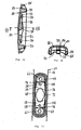
- the Fig. 4 to 7 show the portion of the neck portion 16 with the passage 28 and the recess 46 in different representations and with respect to the Fig. 1 to 3 increased.
- the bottom of the recess 46 (ie, the bottom opening of the passage 28 and the recess 46) is formed almost rectangular with rounded corners. It has a circumferentially continuous circumferential receiving groove 48 which is integrally formed on the support member 26; see in particular 6 and 7 , On the radially inner side of the receiving groove 48 is a continuous circumferential sealing element 50, preferably made of a soft component. In the illustrated embodiment, the sealing element 50 is molded onto the radially inner side wall of the receiving groove 48 in the two-component injection molding. The soft component forms a material bond.
- the material of the sealing element 50 is the same material as in the closure part 30, so that in the injection molding through the sprue 52, for example via a connecting web 54 or other compounds, in the corresponding cavity of the injection molding in the Receiving groove 48 could arrive.
- the sealing element 50 can also be produced together with other soft components of the device body 10.
- the sealing element 50 also be a mounting part, which is manufactured separately and then inserted into the device body 10.
- the sealing element 50 can also be molded or mounted on a cover part 80, which is described below, as an extension of a soft component part 86.
- the holding geometry 34 has on the side facing the head part 14 and on the side facing away from the head part 14, that is, the handle part 18 facing side of the recess 46 each have a support surface 56.
- the two bearing surfaces 56 are, in the longitudinal direction of the device body 10, spaced from each other and lie in the embodiment shown in a plane; this at rest and not, as a result of a pressing force on the head part 14, bent neck portion 16th
- the bearing surfaces 56 are in relation to the bottom 32 at a distance of 0.5 mm to 3 mm, preferably 0.8 mm to 2 mm, in the device body 10 and are preferably arranged closer to the bottom 32 than on the top 20.
- the holding geometry 34 each have a pin 58, which is integrally formed on the device body 10 and the support member 26 and projecting in the direction of the bottom 32 over the respective support surface 56.
- the pins 58 are tapered towards the free end.
- the bearing surfaces 56 have a maximum length of 2 mm to 8 mm, preferably 4 mm to 6 mm and a maximum width of 3 mm to 9 mm, preferably 5 mm to 7 mm.
- the geometric shape of the bearing surfaces 56 is free, but preferably adapted to the peripheral contour of the snap-action disc 36.
- the size of the support surface 56 relative to the snap-action disc 36 is the same, larger or smaller, preferably the support surface 56 is designed with a small oversize relative to the snap-action disc 36.
- the support surface 56 is preferably made of hard component, but it may also be designed only of soft component or a combination of hard and soft component. The design of the support surface 56 may affect the volume of the acoustic signal, the click behavior or the welding of the lid part 80 with the device body 10.
- the pins 58 are preferably circular in shape or elliptical in shape or formed as a rectangle with rounded edges. In addition, other shapes such as a n-corner are possible.
- the pins 58 have a round design a diameter of 0.5 mm to 5 mm, preferably from 0.9 mm to 2 mm. In a more rectangular design, they have a length (in the transverse direction of the snap disc 36) of 1.8 mm to 3 mm, preferably 2.1 mm to 2.7 mm, with a width (in the longitudinal direction of the snap disc 36) of 0.5 mm to 2.5 mm, preferably from 1.5 mm to 2.1 mm. They are in two diameter steps, tapering towards the free end. This serves for centering and welding. Starting from the support surface 56 of the pin has a height of 2 mm to 10 mm, preferably from 4 mm to 6 mm.
- the two bearing surfaces 56 are limited by support surfaces 60, which are preferably perpendicular to the support surfaces 56 and perpendicular to Longitudinal direction of the device body 10 run. These support surfaces 60 are also formed on the support member 26.
- the support member 26 further, in the direction towards the bottom 32 toward open, circular cylindrical blind holes 62, which are formed a stop shoulder 64 forming graduated in diameter.
- the support member 26 between the holding geometry 34 and the top 20, preferably close to this, a passage 28 extending through the film-like separation part 66 with a Weichkomponenten presslass 68 on.
- This separating part 66 is received in the closure part 30.
- the thickness of the separating part 66 influences the elasticity and thus the limit pressing force A G of the toothbrush can be adjusted. It is possible to make the support member 26 in this area so that the partition member 66 has a substantial extent towards the bottom 32. That means the in Fig. 6 shown soft component, can be replaced on the bottom 32 of the closure member 30 except for an extension of the soft component passage 68 or a bar with the width of the soft component passage 68 and the length and width of the closure member 30 toward the bottom 32 by hard component. As a result, the device body 10 in the region of the recess 46 is substantially more stable and less bendable.
- the area of the closure part 30 so that the film-like separation part 66 on the underside 32 of the device body is not or only very thinly covered with soft material. It is possible to design the sprue 52 as a cylinder that is in the extension of the soft component passage 68.
- the film-like separating part 66 can also be designed so that the soft component passage 68 is made very large in terms of dimensions.
- the film-like separating part 66 measured in the passage 28 on the underside 32, can be greatly reduced, so that the radially encircling edge can be reduced to 0.2 mm to 0.8 mm.
- the contour of the soft component passage 68 thereby becomes the oval. But it is also possible to make this as a circular shape.
- the passage in this case has a diameter of 1.2 mm to 4 mm.
- the sprue 52 may be designed in its design variants, inter alia in length so that it ends between 0.1 mm and 0.8 mm, preferably between 0.25 mm and 0.5 mm below the support surface 56. As a result, it can be achieved in all design variants with soft material that the deflection of the snap-action disc 36 is limited by the gate 52 after the state change. After the state change, after a certain further overbending, due to too much pressure, a support of a curvature 72 of the snap-action disc 36 follows.
- the Fig. 8 to 10 show a preferred embodiment of the snap-action disc 36, as it is provided for insertion into the holding geometry 34 of the recess 46. It consists of an approximately rectangular spring steel plate 70, in which in a central region of the bulge 72 is formed, which consists of one of Flat sides of the flat spring steel plate 70, protrudes. Between the two, in the longitudinal direction of the spring steel plate 70 spaced end faces 74 and the buckle 72, the spring steel plate 70 each have a through hole 76. These through holes 76 are intended to be penetrated by mounted in the device body 10 snap disk 36 from the pin 58; compare Fig. 4 to 7 ,
- these through-holes 76 have a diameter of 0.5 mm to 5 mm, preferably 0.9 mm to 2 mm in the case of a round design of the pin 58, and a length (in the transverse direction) of 1.8 mm to 3 mm, preferably 2.1 mm, for a rectangular design of the pin 2.7 mm, at a width (in the longitudinal direction) of 0.5 mm to 2.5 mm, preferably 1.5 mm to 2.1 mm, adjusted to the diameter and the shape of the pin 58.
- the position of the through holes 76 (relative to the center / center of gravity) of the respective end face 74 of the snap-action disc 36 ago is 1 mm to 5 mm, preferably 1.5 mm to 3.5 mm. In the transverse direction, they are preferably arranged on the longitudinal axis or symmetrically to the longitudinal axis.
- end faces 74 are intended to cooperate in the assembled state with the support surfaces 60 by abutting them or, after a slight bending of the device body 10, coming into contact therewith. These interact especially when pressure.
- the end faces 74 may have recesses 78 as shown in the Fig. 8 emerge. These recesses 78 can serve as additional centering next to the pin 58 or as an independent centering be formed when the pins 58 are omitted. When using pins 58 as centering the indentations 78 can also be omitted ie the end faces 74 may be formed straight through.
- the curvature 72 has in the embodiment shown a diamond-like basic shape with rounded corners. However, it is also conceivable that the bulge 72 has a circular or other basic shape.
- the dimensions of the curvature are in the length between 3 mm and 12 mm, preferably between 6 mm and 9 mm.
- the width of the curvature is between 2 mm and 8 mm, preferably between 3.5 mm and 6.5 mm.
- the height of the curvature is between 0.1 mm and 0.5 mm, preferably between 0.15 mm and 0.35 mm.
- the position of the curvature is preferably symmetrical to the longitudinal and to the transverse axis of the spring steel plate 70, a different arrangement is still possible.
- the snap disk 36 it is possible to equip the snap disk 36 with detents, which is not shown in the figures. These notches are there to cling firmly in the plastic of the support surface 56 when they are pressed into it during assembly. This is to avoid that the snap-action disc 36 acts like a razor blade and the pin 58 shears / cut off due to the stress in use of the function. In addition, is increased by a snap disc designed in this way, the resistance to stress against the direction of use.
- the detents can be formed in different ways from the plate of the snap disk. On the one hand, they can as on the other hand, they can protrude from the plane of the snap-action disc 36 in the region of the support surface 56 and in this way strike the support surface 56 perpendicularly.
- the catch is formed directly in the region of the through holes 76 of the pin 56. It is formed only a recess, which on the one hand forms the through hole 76 and from which on the other hand also protrudes the catch.
- the catch is from the bottom of the snap-action disc 36 0.1 mm to 0.8 mm, preferably 0.3 mm to 0.6 mm.
- the snap disc 36 considered alone is an element with a resting state and a tripped state.
- the resting state is the unloaded state when the snap-action disc 36 is considered alone. It does not produce any other state without external influence, so it is stable.
- the triggered state is when the snap-action disc 36 is bent and the acoustic signal is triggered.
- the snap-action disc 36 in the tripped state automatically wants to return to the idle state without outside influence, as soon as the action which has led it from rest to the tripped state is eliminated.
- the Fig. 11 to 15 show a cover member 80 for closing the passage 28 and the recess 46 on the bottom 32 of the device body 10 to the environment, so that in the neck portion 16 against the environment, preferably sealed sealing cavity 82 is formed; compare to this Fig. 19 and 20 ,
- the cover part 80 has a peripheral frame 84, preferably of a hard component.
- the opening formed by the frame 84 is closed in the embodiment shown by means of a molded soft component part 86.
- the cover part 80 is made of a single component, preferably a hard component.
- the hard component is preferably the same material as the support member 26, so that the welding works optimally.
- the preferred material used is polypropylene.
- the molded soft component part 86 forms a kind of membrane, at least partially without hard material support. In this case, the elasticity and thus the limit pressing force A G of the toothbrush can be adjusted by the geometric configuration of this surface and with the aid of the variation of the layer thickness.
- An alternative embodiment variant would be to mold the cover part 80 only from the frame 84 and leave the soft component part 86 open. After assembly of the snap-action disc 36 and the welding of the cover part 80 to the device body 10, a sealing element, for example in the form of a tube or heat-shrinkable tube, could then be brought to close over the opening.
- the frame 84 has on its upper side, which faces the apparatus body 10 and the support member 26, a projecting and preferably continuous circumferential bead 88, which is intended, when mounting the cover member 80 on the device body 10 in the Engaging receiving groove 48; compare in particular 4 and 6 ,
- the bead 88 has a tapered cross-section towards the free end. This shape can serve as an energy concentrator during ultrasonic welding of the bead 88 and thus of the cover part 80 with the device body 10 or support part 26. This energy concentrator ensures the connection of cover part 80 and device body 10 or support member 26 during welding, to this end it is melted.
- mounting pins 90 which are formed gegen Eisen the blind holes 62 and are destined to engage in the assembly of the cover member 80 with the blind holes 62 in engagement.
- the mounting pins 90 are preferably not the same length on the side of the head part 14 and the handle part 16.
- the mounting pin 90 on the side of the head part 14 is preferably longer than that on the side of the handle part 16. Nevertheless, the reverse configuration as well as the configuration with the same length fastening pin 90 is possible.
- contact surfaces 92 are formed according to the bearing surfaces 56 on the frame.
- the contact surfaces 92 are in the unloaded state, analogous to the support surfaces 56 arranged in a plane. In these contact surfaces 92 a respective receiving blind hole 94 is formed, in which during the assembly of the cover part 80 of the associated pin 58 engages; compare Fig. 4 to 7 ,
- the tongue 96 is triangular, but other shapes are possible.
- a semicircular geometry may serve as a tongue 96, important in all geometries being that they taper towards the free end or an actuating knob 98, respectively.
- the length of the tongue 96 is from its starting point 2 mm to 10 mm, preferably 3 mm to 6 mm, and its width (at the starting point) is 2 mm to 10 mm, preferably 3.5 mm to 6.5 mm.
- the actuating knob 96 is preferably an element with a circular, elliptical or n-shaped base from which a cone or pyramid rises.
- the width and the length of the actuating nub 96 is between 0.2 mm and 1 mm, preferably between 0.4 mm and 0.6 mm.
- the height of the element is between 0.1 mm and 1.2 mm, preferably 0.3 mm to 0.8 mm.
- the tongue 96 may be at least partially firmly connected to the soft component part 86 as a result of the injection molding process. As in Fig. 14 can be seen, the tongue 96 rises in the direction of its free end from the plane formed by the contact surfaces 92, from. The reason for this is that the tongue 96 or the actuating knob 98 must not touch the snap-action disc 36 in the installed state before and during welding. The welding with ultrasound brings with it vibrations on the snap disc 36, which, in contact with the tongue 96 and the associated Actuating knobs 98 would bring a melting of the tongue 96 and the Betreliriensnoppens 98 with it.
- the lid part 80 has a length of 20 mm to 30 mm, preferably 23 mm to 27 mm.
- the width is between 5 mm and 11 mm, preferably 7 mm to 9 mm.
- the soft component part 86 has a thickness of at most 1 mm, preferably at most 0.8 mm.
- Fig. 16 shows in bottom view, the recess 46 in the neck portion 16 with inserted into the holding geometry 34 snap disk 36 according to the Fig.
- the snap disc 36 lies with its head portion 14 facing the first end portion 100 - between the buckle 72 and this side end face 74 - on the corresponding support surface 56 and facing away from the head part 14 and thus the handle portion 18 facing the second end portion 102 - between the buckle 72nd and this side end face 74 - on the corresponding support surface 56 surface.
- the pins 58 penetrate the through holes 76; in a preferred way, they hold the inserted snap-action disc 36 temporarily by means of frictional engagement.
- Fig. 16 removable, that the snap disc 36 rests with their end faces 74 on the respective support surfaces 60.
- Fig. 4 and 16 or by consideration of Fig. 20 clearly visible that the bulge 72 is exposed; ie, that the bulge 72 having, between the first end portion 100 and the second end portion 102 arranged center portion is exposed and not on the device body 10 and support member 26 is present.
- the 17 to 19 show a toothbrush 12 according to the invention with a device body 10 according to the Fig. 1 to 3 , a snap disk 36 inserted into the recess 46 and the lid member 80 sealingly mounted on the apparatus body 10 and the supporting member 26, respectively. Further, the bristle bundles 104 inserted into the bristle receiving holes 24 are shown.
- Fig. 20 shows the portion of the neck portion 16 with the recess 46, the inserted into the holding geometry 34 snap disk 36 and mounted on the support member 26 lid member 80 opposite Fig. 19 increased.
- the reference numerals of the individual parts correspond to the reference numerals used above.
- the snap disc 36 is held clamped with its first end portion 100 and second end portion 102 between the bearing surfaces 56 and the corresponding contact surfaces 92.
- the through holes 76 by cross-pin 58 engage in the receiving blind holes 94 of the lid portion 80 a.
- the fastening pins 90 of the cover part 80 engage in the blind holes 62 of the support part 26, so that the stop shoulders 64 abut the counter stop shoulders of the fastening pins 90.
- the bead 88 of the cover part 80 is arranged in the receiving groove 48 of the support member 26, wherein the sealing member 50 injection molded on the support member 26 sealingly abuts against the radially inner side wall of the bead 88.
- the seal achieved in this way completely closes the cavity 82, even if the material connection, ie the welding, is provided only in the region of the fastening pins 90.
- the bulge 72 of the snap-action disc 36 points in the direction towards the underside 32 and the tongue 96 is slightly spaced from the bulge 72.
- the different arrangement of the buckle 72 is possible, but requires adjustments to the mechanism or its arrangement.
- the curvature 72 is preferably directed in all embodiments in the direction of the cover part 80.
- This clamping connection can take place, for example, by a frictional connection between the fastening pins 90 and the corresponding blind holes 62.
- the clamping connection takes place additionally or alternatively between the bead 88 and the sealing element 50.
- the cover part 80 is preferably fixed to the device body 10 by means of ultrasonic welding.
- the mounting pins 90 are firmly welded in the blind holes 62 on the device body 10 by means of spot welding.
- the stop shoulder 64 and integrally formed on the mounting pins 90 counter shoulders.
- the geometry combination of the counter shoulders and the stop shoulders 64 as energy concentrator.
- the neck portion 16 in the finished state of the toothbrush 12 and the oral hygiene device on the cavity 82, in which the snap disc 36 is arranged.
- the snap disk 36 is due to their low material thickness a relatively sensitive element in the mechanism. Overload, be it on train or on pressure, can affect the snap function. The problem here is that the user want to test the mechanism and in this way by over bending the snap disc unintentionally affect the snap function. Solutions to this problem are in the FIGS. 21 and 22 shown.
- Fig. 21 shows in plan view a further preferred embodiment of the cover part 80. This is exactly the same as in the Fig. 11 to 15 shown and described above. The only difference is that, from the contact surface 92 facing away from the head part 14, towards the tongue 96, an abutment tongue 106 protrudes.
- the tongue 96 facing front side 108 is formed in a preferred manner opposite the free end portion of the tongue 96, so that between the tongue 96 and the stop tongue 106, in the idle state of the device body 10, a gap 110, in the longitudinal direction of Device body 10 measured constant width, is present.
- the stop tongue 106 in cooperation with the tongue 96, forms stop means 112 in order to limit the bending load of the snap disc 36 when the oral hygiene device or the toothbrush is in use.
- the stop tongue 106 limits the compressive stress in cooperation with the tongue 96, the load on the snap-action disc 36 in the case of tensile stress is not limited in this way.
- the gap 110 is 0.5 mm to 2 mm, preferably 0.8 to 1.5 mm wide.
- the gap can be adjoined laterally by gap connection sections, in the region of which the distance between the tongue 96 and the stop tongue 106 is greater than the width of the gap 110.
- the bending stress of the snap-action disc 36 should be limited or at least reduced by a corresponding design of the cover part.
- the stop tongue 106 may also be formed so that it, like the tongue 96, is not laterally connected to the frame 84 and forms the counter stop only in the region of the tip of the tongue 96.
- the in Fig. 21 shown gap 110 on the side of the stop tongue 106 further toward the short-side end of the lid part 80th
- Fig. 22 shows in bottom view another possible embodiment of the holding geometry 34 and the snap disk 36. It is on the above described and in the Fig. 8 to 10 Snap plate 36 shown a boundary plate 116 placed, which is to protect the snap disk 36 from overloading. The comparison between the Fig. 16 and 22 shows the difference well. Directly on the snap disc 36, the boundary plate 116 is placed; this bounding plate 116 is shaped like a frame. The outline follows the outer contour of the snap disk 36 and inside a recess in the region of the curvature of the snap disk 36 is designed. When the snap-action disc 36 and the restriction plate 116 are mounted, ie superimposed, the edge of the bulge rests directly against the edge of the recess.
- the boundary plate 116 has a thickness of 0.2 mm to 0.8 mm, preferably 0.3 mm to 0.5 mm, and is preferably made of spring steel (St. 60).
- the limiting plate 116 is immovably fixed to the pin 58 in the first end section 100, while in the region of the second end section 102, the pin 58 is movably mounted in a through hole 76 designed as a slot.
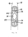
- FIG. 34 shows a design variant analogous to that in Fig. 22 , The differences are shown on the one hand in the area of the through holes 76 and the associated pins 58, which are designed as a rectangle with rounded corners, and on the other hand in the connection / attachment between the limiting plate 116 and the snap disc 36, which are shown as circles 117. It can also be seen that the boundary plate 116 does not have the same length as described, as described Snap disk 36, but is designed a little shorter. The limiting plate 116 and the snap disc 36 also have through holes 76, which are larger than the associated pin 58, so that the movements for triggering the clicking noise are possible.
- the pin 58 is located at the front end of the slot or through hole 76.
- the tensile load of the snap disk is prevented because the pin 58 can not move in the slot in train.
- the pressure load is possible, up to the stop of the pin 58 at the opposite end of the slot or until the boundary plate abuts against the support surface 60.
- the limitation of the tensile and / or compressive load is possible. Due to the variant shown, the various interface options between pin 58 and through hole 76 can be seen. The possibilities can be used in any combination.
- the pin 58 may at the other end (as in Fig.
- the length of the delimiting plate 116 is preferably designed so that at the end faces of the snap disk 36, between the end faces of the Begrenzungsplättchens 116 and the support surface 60 each have a distance of 0.1 mm to 0.25 mm is present.
- support means in the passage 28 for this purpose, for example, a body made of hard material are inserted, on which a notch is formed, which in turn the bend in only one certain area permits.
- the depth of the notch does not matter, as the angles are important; a deep notch has the advantage that the stop is greater when bent and thus the limit is stronger.
- a total angle of about 13 ° brings in this case a limitation of the movement to 0.5 mm to 0.6 mm in the region of the snap disk from the rest position into the position at maximum load.
- the device body 10 itself be designed with a closure member 30 made of hard material.
- the resulting stiffening of the device body 10 may bring a support for the snap-action disc 36.
- the operation of the toothbrush 12 according to the invention or of an oral hygiene device can be carried out with the aid of the in the Fig. 23 shown diagram are explained. It shows the force F generated by the toothbrush 12 as a function of the deflection W of the head part 14; see also in Fig. 19 the arrows W and F for the deflection or the force.
- the neck part 16 bends as a result of the elastic properties of the device body 10 or of the support part 26.
- the relationship between the path W made by the bending back and the (reaction) force F generated by the device body 10 is preferably at least approximately linear. Which basically results in dependence of the geometry. Due to the holding geometry 34, both a torque and a compressive force is transmitted to the snap disc 36.
- a limit pressing force A G is reached at a limit bending B G
- the snap-action disc 36 switches over into its counter-position, producing an acoustic warning signal.
- This is in the diagram of Fig. 23 indicated by a sudden reduction of the force F.
- the pressing force then continues to increase until it approaches asymptotically to a limit force.
- the snap-action disc 36 returns to its original position upon reaching the further limit pressing force A G ' or the further limit bending B G' and in turn emits an acoustic warning signal.
- the characteristic shows a hysteresis.
- the snap-action disc is designed so that the achievement of the limit pressure force A G and the triggering of the snap-action disc only entails an insignificant change in the elasticity of the toothbrush. As a result, the head part 14 does not tilt when reaching the limit pressing force A G. The user can still use his toothbrush 12 if he expends too much force. It is only the goal to warn the user acoustically without significantly changing the elastic properties.
- the further boundary pressing force A G 'for the warning signal when resetting is set lower than (on triggering see Fig. 23 ), so that the user practically has to relieve the toothbrush 12, and thus consciously determines that he has used too much pressure. This leads to a learning effect for the user.
- FIG. 23 The various limit pressure forces and limit bends are in Fig. 23 shown.
- a typical curve in the application in the finished product is that the curve is traversed from the zero point during force / pressure application, passes A G / B G and moves along the curve with increasing W. With subsequent relief, you move on the same curve, to near G / G G , from this point, the ratio moves on the lower curve part to the point A G ' / B G' and from there is the line the same again for the discharge as for the burden.
- the points A G / B G and A G ' / B G' may also be the same.
- the limit pressing force A G is selected between 150 g and 500 g, preferably between 250 g and 450 g, particularly preferably about 350 g.
- the corresponding limit bending B G with which the head part 14 deviates in consequence of the bending of the neck part 16, is for example between 5 mm and 15 mm.
- the further limit pressing force A G ' is preferably between 50 g and 500 g, more preferably between 50 g and 250 g or 350 g, the associated further boundary bend B G' is between 1 mm and 15 mm. If A G is not equal to A G ' , B G' is between 2 mm and 6 mm, preferably between 2 mm and 4 mm. It should be noted that the values for B G , B G ' , A G' and also for A G depend on many factors to be designed. These include, among other things, geometry, material and manufacturing process of snap disk 36, Device body 10, cover part 80 and the associated assembly.
- the gap 110 is selected such that the tongue 96 and the stop tongue 106 only touch each other after the snap disc 36 has jumped into the counter position.
- the width of the gap 110 is, for example, 0.5 to 2 mm, preferably 0.8 to 1.5 mm.
- the snap-action disc 36 is protected against overstressing by a limiting plate 116. Also in this embodiment, it is possible to use a lid part 80 according to Fig. 21 to use.
- the cover part 80 preferably has no stop tongue 106.
- the slings of this type could, for example, in the Recess 46 and be arranged in the passage 28.
- the tongue 96 comes with its actuating knob 98 during bending of the neck portion 16 respectively at the bulge 72 of the snap-action disc 36 to the system and acts on bending the neck portion 16 on this one.
- the limit pressing force A G or limit bending B G can be set very precisely or the triggering of the snap disk becomes more accurate.
- the tongue 96 together with its actuating nub 98 can be omitted, since they are designed as an adjustment for the precise release of the mechanism.
- the retaining geometry 34 on the cover part 80 in particular on its frame 84, accordingly.
- the support surface 56 and the pins 58 are integrally formed on the frame 84.
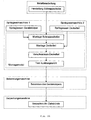
- a first possible method as in Fig. 24 is shown schematically, are in a first step on an injection molding machine 1, optionally in Two- or multi-component injection molding, the device body 10 and on a Spritzgiessmaschiene 2, optionally also in two- or multi-component injection molding, the lid member 80 produced.
- the snap disk 36 is produced in a metal processing station, for example in a stamping and embossing process. This step can also be outsourced, ie it does not have to take place in the immediate vicinity of the injection molding process.
- the snap disc 36 is inserted into the holding geometry 34 of the transferred device body 10 in an assembly module; see also Fig. 16 ,
- the assembly module is integrated directly into the production of the injection molding machine 1, ie linked with it.
- the pins 58 are preferably inserted into the through-holes 76 of the snap-action disc 36. This then comes with their end portions 100, 102 on the support surfaces 56 and the support surfaces 60 to the plant.
- a cover module 80 which is likewise supplied to the assembly module, is mounted on the device body 10 provided with the snap-action disc 36.
- the fastening pins 90 engage with the corresponding blind holes 62, the bead 88 with the receiving groove 48 and the pins 58 engage with the associated receiving blind holes 94.
- the clamping connection described above is produced.
- the cover part 80 is permanently connected to the device body 10. This is preferably done by a welding process, preferably ultrasonic welding.
- spot welds are preferred in which the sonotrode is attached to the cover part 80 or the frame 84 in the fastening pins 90 and which touches the cover part 80 only at these locations. In the remaining areas of the surface an exemption is created.
- it is also a 3D welding, in particular a 3D ultrasonic welding, possible.
- the sonotrode is attached to the lid at the bead 88 on the frame 84, whereby the bead 88 welded to the device body 10 in the region of the receiving groove 48.
- spot welds are carried out, since they are compared to the 3D welding process less expensive, less complicated and also not so critical. Other connection methods are possible.
- the assembly module is carried out in a fifth step by means of a designated in the diagram with "test tripping weight" function control, a review of Function of the snap-action disc 36 or of the assembled and welded overall system.
- This test is necessary because the function of many different parameters, for example, the material properties of the device body 10 and snap disk 36 depends.
- the head part 14 can be acted upon by means of a plunger with a test force which is greater than the limit pressing force A G.
- the path W which the head part 14 performs under the load due to the bending of the neck part 16 can be detected.
- the acoustic warning signal can be determined at the same time by means of a microphone, which generates the snap disc 36 when jumping.
- the return of the snap disk 36 can be checked in their initial position when moving back the plunger. If the measured values lie within predefined limits, the functionality is OK.
- the head part 14 is acted upon at least twice with the force described above, wherein only the second application is evaluated for the function control.
- the first loading is an activation of the mechanism, its trigger values may differ from the values of the further triggering.
- This test of the release weight preferably takes place in one step directly after welding. In principle, however, the sequence of the test in the process sequence can be carried out at different points; it can also happen just before or after the bristles of the toothbrush or directly before the toothbrush is packed. The test is therefore not strictly bound to the mounting module.
- the test of the tripping weight but takes place from economic Reasons preferably as early as possible in the process, so that even more value is added to the defective product in case of erroneous function.
- For the process integration of the test of the release weight of course, it must also be considered to what extent the process steps following the test affect the product or, in particular, the function.
- the assembly module may, for example, in a known manner comprise a turntable with circumferentially distributed holding elements for the device body 10. In this case, this is held in a preferred manner in the region of the handle portion 18. By indexing the turntable from one workstation to the next successively the above-mentioned process steps two to five.
- the assembly module can also be constructed on a chain conveyor or another transport system.
- the assembly module can of course be understood as several stations with manual workstations and corresponding auxiliary devices. Depending on the manufacturing site, this can be cheaper than a complex, automated assembly system. This applies to all assembly tasks mentioned in this document.
- the injection molding machine 1 and the assembly module are connected in line or the assembly module is integrated into the process flow and the injection molding machine 1, while the metalworking and the injection molding machine 2 produce offline and the Snap discs 36 and cover parts 80 are supplied from an intermediate storage the mounting module.
- the finished tested device body 10 is fed to a bristle machine, in which, in a known manner, for example by means of anchor wire sections, the bristle bundles 104 forming bristles are inserted into the bristle receiving holes 24 of the head part 14.
- a bristle machine in which further processing takes place in a known manner, for example, the free ends of the bristles are profiled and rounded.
- the finished toothbrushes 12 are fed to a packaging machine, in which they are packed, for example, in blisters.
- a consumer packaging in which the neck portion 16 can elastically deflect. This allows the user to try the snap mechanism at the point of sale. This can be achieved, for example, with recesses in the packaging or by a movable element of the packaging.
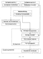
- the injection molding machine 1 works in line with the mounting module is in the process according to Fig. 25 the assembly module in line with the injection molding machine 2, the production of the lid part 80, connected. While metalworking and the injection molding machine 1 produce offline. Moreover, the procedure is the same as that used in connection with the Fig. 24 described.
- the injection molding machine 1 and the injection molding machine 2 are connected in line so chained to the mounting module.
- a buffer can be connected between the various process steps. While the snap discs 36 were made offline and fed to the mounting module. For the rest, the process steps take place in exactly the same way as in connection with the Fig. 24 explained.
- Fig. 27 In another possible method, as in Fig. 27 is indicated, both by means of the injection molding machine 1, the device body 10 and by means of the injection molding machine 2, the lid parts 80 and by means of the metalworking station, the snap discs 36 offline, that is made independent of each other. The corresponding parts are then fed to the separately designed, not linked to a process, mounting module. There, the assembly of the snap-action disc 36 and the lid part 80, the welding and the function control in exactly the same manner as in connection with Fig. 24 described.
- the assembly module with the bristle machine in line. It can, as in Fig. 28 shown, the injection molding machine 1, the injection molding machine 2 and the metalworking station offline the device body 10, the cover parts 80 and the snap discs 36 manufacture. These parts are then fed to the mounting module on the bristle machine for assembly, welding and testing. Although the brushing of the toothbrush 12 also takes place in the bristle machine, this process is arranged after the assembly process. Incidentally, the individual process steps are the same as in connection with Fig. 24 explained.
- the mounting module is also associated with the Beborstungsmaschine in line, however, it is first bristled and only then mounted.
- the device body 10 produced offline by means of the injection molding machine 1 and supplied to the bristle machine 10 are first moved into well-known fashion. Subsequently, the bristled device body 10 are supplied to the mounting module, where in the same manner as in connection with Fig. 24 described, the snap-action disc 36 and the lid part 80 are mounted, the welding of the lid part 80 with the device body and then the function check is carried out.
- the packaging of the finished toothbrushes then takes place in a packaging machine.
- the integration of the assembly process in the bristle machine before the bristles brings opposite the variant mount after the bristles (see Fig. 29 ) has the advantage that a possible source of error can be switched off.
- the bristle process basically involves many vibrations to which the device body 10 is exposed. Through the recess 46 in the neck area of the body is weakened at this point. If he is exposed to the vibrations in this state, this may have an influence on the properties of the device body 10 in the region of the neck part 16.
- the lid member 80 is mounted when the apparatus body 10 is subjected to the vibration, the neck member 16 is more stable and the aforementioned change in properties can be avoided.
- this also applies to the in Fig. 24 to 27 shown processes; the assembly took place before the bristles were carried out.
- the device body 10 produced offline by means of the injection molding machine 1 are fed to the bristle machine, where the head parts 14 with the bristle bundles 104th be provided.
- the offline bristled device body 10 are then fed to the mounting module, same as the offline produced snap discs 36 and cover parts 80.
- the mounting module itself is as in the process in Fig. 27 an independent process that is not directly linked.
- the assembly module as described above, the assembly of the snap-action disc 36 and the cover part 80, the welding of the cover part with the device body 10 and the function control.
- the finished toothbrushes 12 are supplied for packaging the packaging machine.
- the steps are in turn analogous to those related to Fig. 24 designed steps described.
- Fig. 31 shows.
- the device body 10 produced offline by means of the injection molding machine 1 are fed to the bristle machine, bristled and stored again.
- the bristled device body 10 are fed to the mounting module in the next step.
- the snap discs 36 and the lid parts 80 produced by means of the injection molding machine 2 are also supplied to the mounting module, where in the same manner as described above, the assembly, the welding and the function check. From the assembly module then arrive the finished controlled toothbrushes 12 in line ie directly linked to the packaging machine.
- the steps are in turn analogous to those related to Fig. 24 designed steps described.
- the integration of the mounting module in the process can bring significant benefits. So are the parts or at least a part of the parts to be machined already aligned, ie kept defined when the mounting module is integrated directly in line with a system. This means that at least one alignment process is eliminated. At most, one disadvantage can be the process efficiency. The concatenation of more process steps also entails that the efficiency decreases. But also that, for example, dependable processes or processes that require a certain constant run to function optimally, suddenly no longer produce the same product quality due to the integration of the assembly.
- the assembly of the snap disk 36 produced offline is then carried out in the holding geometry 34 of the relevant cover part 80; This is done in the same way as when the holding geometry 36 is formed on the device body 10.
- a device body 10 produced offline by means of the injection molding machine 1 is in each case supplied to the assembly module and mounted there on the cover part 80 provided with the snap-action disk 36.
- a clamping connection is made.
- the finished toothbrushes 12 are removed from the assembly module and fed to the corresponding machines or the corresponding intermediate bearings for bursting and packaging.
- the reverse assembly is independent of the manufacturing order.
- the embodiment of the insertion of the snap-action disc 36 in the cover part 80 and the subsequent mounting on the device body 10 entails that the assembly takes place from the underside of the toothbrush 12 ago.
- this type of mounting can be advantageous, possibly on a bristle machine, when the device body 10 is held in the head part 14 and then the assembly should take place directly integrated.
- the production process can also be linked, for example, by the injection molding process with the Beborstungs- and the packaging process are completely or parts thereof linked.
- a bounding pad 116 as in FIG Fig. 22 used, this is mounted together with the snap disc 36.
- the design There are various possibilities for the design.
- the limiting plate 116 to the snap-action disk 36 in the device body 10 before assembly.
- the two parts can be connected to each other by spot welding, soldering, gluing, riveting or other methods. This makes it possible to process as in the FIGS. 24 to 33 shown to drain. The process does not require any fundamental adjustment, as the connected part (consisting of snap-action disc 36 and restriction plate 116) can be treated as a unit like a single snap-action disc 36.
- a relative movement between the snap disc 36 and the boundary plate 116 is at least partially still possible. This means that the connection is preferably made only on one side of the unit, preferably in the region of the end faces 74.
- the bounding pad 116 When the bounding pad 116 is connected, it may be necessary to realize additional through-holes on the snap-action disc 36. For example, if the two parts are riveted, this may be necessary.
- the attachment of the two parts preferably occurs in the region around the through holes 76 on the snap-action disc 36 and only on one side of the snap-action disc 36.
- the manufacture of toothbrushes by the AFT method is well known.
- the Fig. 33 shows a possible procedure for the production of toothbrushes according to the invention according to the AFT method.
- device bodies 10 are produced, which are then fed to the mounting module associated with the AFT bristle machine. This is also the produced in the metalworking station snap discs 36 are supplied, where their assembly takes place in the device body 10, as described above.
- Cover parts 80 produced by means of the injection molding machine 2 are likewise fed to the assembly module, where - as described above - they are mounted on the device body 10 provided with a snap-action disc 36.
- the head part 14 of the device body 12 in this case not with Brstenaufnahglöchern 24th but with a recording contour for a carrier plate (AFT plate) is provided.
- These support plates are produced by means of an injection molding machine 3, preferably from a hard component or in the multi-component injection molding of one or more hard components and one or more soft components.
- the carrier plates are fed to the Beborstungsmaschine where they are provided in a known manner with bristles. From the bristle machine arrive in line the bristled carrier plate to the mounting module, where they are used in the head part 14.
- the cover part 80 and, on the other hand, the support plate 12 are firmly connected to the device body 10, preferably by means of ultrasonic welding.
- the welding can be done in two separate steps or in a single step, depending on the configuration of the toothbrush 12 and the welding device. Welding in one step may in turn occur by means of two separate welding devices (two sonotrodes) or by a common welding device (a single sonotrode), in which case the arrangement of the lid part 80 and the whole mechanism should pass on the upper side 20 of the toothbrush 12 ,
- the lid member 80 and the carrier plate are welded independently of each other, ie, in two separate steps and by means not connected sonotrodes.
- the individual welds can be optimized.
- the function control is carried out in the assembly module.
- the finished toothbrushes 12 then arrive in the packaging machine.
- the snap discs 36 is preferably a spring steel, in particular a stainless steel, such as X10CrNi which corresponds to a steel 1.4310 used.
- a surface treatment or surface refinement There is the possibility, in particular if no stainless steel is used, to subject the snap disks 36 to a surface treatment or surface refinement. They can be coated, for example, with silver, nickel, gold or tin. This may be desirable in particular when transparent or translucent plastics are used, so that the snap-action disc 36 is visible or recognizable from the outside.
- the snap discs 36 have a length between 5 mm and 25 mm, preferably between 13 mm and 17 mm and their width is 3 mm to 9 mm, preferably 5 mm to 6.6 mm.
- the thickness of the sheet for producing the snap discs 36 is 0.03 mm to 0.5 mm, preferably 0.05 mm to 0.1 mm.
- the bevel of Outside is between 3 ° and 12 °, preferably between 6 ° and 9 °.
- the snap disc 36 may be made of plastic, preferably a hard component.
- a plurality of through holes 76 can be configured per side in order to optimally position and hold the snap-action disc 36. However, these should always be designed symmetrically to the longitudinal and transverse axis.
- toothbrushes 12 according to the invention can be produced by the known IMT method (In Mold Tufting) or the IAP method (Integrated Anchorless Production) as well as by other brush production methods.
- bristle shapes are possible for the practice of the invention.
- Conventional cylindrical bristles as well as sharpened bristles can also be used in combination, but soft elastic cleaning and massage elements can also be integrated in the bristle field.
- the toothbrushes 12 may have a length up to 210 mm. Preferably, their length is between 120 mm and 140 mm or between 190 mm and 200 mm.
- the head part 14 is between 8 mm to 20 mm, preferably 10 mm to 16 mm wide.
- the length of the head part 14 is 10 mm to 35 mm, preferably 15 mm to 24 mm or 26 mm to 30 mm.
- the neck portion 16 preferably has a width and height of 4 mm to 14 mm, preferably 6 mm to 10 mm.
- the thumb rest 38 is preferably spaced apart by 70 mm to 130 mm, in particular from 80 mm to 110 mm, from the free end of the grip part 18.
- design variants shown in this document are exemplary and the individual forms and elements of these design variants can be combined with other design variants without departing from the scope of this invention.
- Figures shown mechanism can not be used only for an oral hygiene device. It is conceivable to use this mechanism analogously for other applications in which the contact pressure has to be monitored.
Landscapes
- Physics & Mathematics (AREA)
- Acoustics & Sound (AREA)
- Brushes (AREA)
Priority Applications (1)
| Application Number | Priority Date | Filing Date | Title |
|---|---|---|---|
| EP20130005479 EP2700332A3 (fr) | 2010-02-26 | 2011-02-04 | Appareil d'hygiène buccale, en particulier brosse à dents |
Applications Claiming Priority (3)
| Application Number | Priority Date | Filing Date | Title |
|---|---|---|---|
| EP10001977A EP2361528A1 (fr) | 2010-02-26 | 2010-02-26 | Appareil d'hygiène buccale, en particulier brosse à dents, et son procédé de fabrication |
| EP11702943.9A EP2538817B1 (fr) | 2010-02-26 | 2011-02-04 | Appareil d'hygiène buccale, en particulier brosse à dents, et son procédé de fabrication |
| EP20130005479 EP2700332A3 (fr) | 2010-02-26 | 2011-02-04 | Appareil d'hygiène buccale, en particulier brosse à dents |
Related Parent Applications (1)
| Application Number | Title | Priority Date | Filing Date |
|---|---|---|---|
| EP11702943.9A Division EP2538817B1 (fr) | 2010-02-26 | 2011-02-04 | Appareil d'hygiène buccale, en particulier brosse à dents, et son procédé de fabrication |
Publications (2)
| Publication Number | Publication Date |
|---|---|
| EP2700332A2 true EP2700332A2 (fr) | 2014-02-26 |
| EP2700332A3 EP2700332A3 (fr) | 2015-04-29 |
Family
ID=42537585
Family Applications (3)
| Application Number | Title | Priority Date | Filing Date |
|---|---|---|---|
| EP10001977A Withdrawn EP2361528A1 (fr) | 2010-02-26 | 2010-02-26 | Appareil d'hygiène buccale, en particulier brosse à dents, et son procédé de fabrication |
| EP11702943.9A Not-in-force EP2538817B1 (fr) | 2010-02-26 | 2011-02-04 | Appareil d'hygiène buccale, en particulier brosse à dents, et son procédé de fabrication |
| EP20130005479 Withdrawn EP2700332A3 (fr) | 2010-02-26 | 2011-02-04 | Appareil d'hygiène buccale, en particulier brosse à dents |
Family Applications Before (2)
| Application Number | Title | Priority Date | Filing Date |
|---|---|---|---|
| EP10001977A Withdrawn EP2361528A1 (fr) | 2010-02-26 | 2010-02-26 | Appareil d'hygiène buccale, en particulier brosse à dents, et son procédé de fabrication |
| EP11702943.9A Not-in-force EP2538817B1 (fr) | 2010-02-26 | 2011-02-04 | Appareil d'hygiène buccale, en particulier brosse à dents, et son procédé de fabrication |
Country Status (5)
| Country | Link |
|---|---|
| US (1) | US8973202B2 (fr) |
| EP (3) | EP2361528A1 (fr) |
| ES (1) | ES2445795T3 (fr) |
| TW (1) | TWI517804B (fr) |
| WO (1) | WO2011103962A1 (fr) |
Families Citing this family (10)
| Publication number | Priority date | Publication date | Assignee | Title |
|---|---|---|---|---|
| USD676245S1 (en) | 2010-03-30 | 2013-02-19 | Colgate-Palmolive Company | Oral care implement |
| USD754442S1 (en) * | 2013-07-17 | 2016-04-26 | Colgate-Palmolive Company | Toothbrush |
| CN106659555B (zh) | 2014-07-02 | 2020-09-22 | 皇家飞利浦有限公司 | 自动牙刷的轴 |
| TWI565437B (zh) * | 2015-04-02 | 2017-01-11 | 李德恭 | 定力刷具 |
| KR20170140248A (ko) | 2015-04-02 | 2017-12-20 | 테-쿵 리 | 일정 하중 브러시 |
| US10172445B2 (en) | 2016-11-07 | 2019-01-08 | Colgate-Palmolive Company | Packaged oral care implement and oral care implement thereof |
| GB2566021B (en) * | 2017-08-29 | 2022-05-04 | Oluwafemi Oluwadare Oluwaseyi | Toothbrush |
| US10925384B2 (en) * | 2018-04-16 | 2021-02-23 | Colgate-Palmolive Company | Oral care implement |
| JP7531403B2 (ja) | 2018-12-27 | 2024-08-09 | ライオン株式会社 | 歯ブラシ |
| US11478068B2 (en) * | 2019-01-15 | 2022-10-25 | Pixart Imaging Inc. | Electric toothbrush adopting force sensing array |
Citations (4)
| Publication number | Priority date | Publication date | Assignee | Title |
|---|---|---|---|---|
| DE3840136C1 (fr) | 1988-11-29 | 1990-05-17 | Blendax Gmbh, 6500 Mainz, De | |
| DE9310112U1 (de) | 1993-07-07 | 1994-06-09 | Hoffmann, Kay, Dr., 53639 Königswinter | Zahnbürste |
| EP0848593B1 (fr) | 1995-09-08 | 1999-11-10 | CORONET-Werke Gesellschaft mit beschränkter Haftung | Brosse a dents |
| WO2004010822A1 (fr) | 2002-07-26 | 2004-02-05 | Jordan As | Brosse a dents a ressort a lames pour garantir une pression correcte |
Family Cites Families (21)
| Publication number | Priority date | Publication date | Assignee | Title |
|---|---|---|---|---|
| US2083217A (en) | 1934-07-14 | 1937-06-08 | Edwin I Brothers | Prophylactic device for the oral cavity |
| US4520526A (en) | 1984-06-22 | 1985-06-04 | Peters Charles W | Resiliently flexible toothbrush |
| DE3612108A1 (de) | 1986-04-10 | 1987-10-15 | Rainer Dr Seib | Zahnbuerste mit elastischem verbindungselement zwischen buerstenkopf und griff |
| WO1988006417A1 (fr) * | 1987-02-27 | 1988-09-07 | Blendax-Werke R. Schneider Gmbh & Co. | Brosse a dents |
| US5146645A (en) | 1991-03-01 | 1992-09-15 | The Procter & Gamble Company | Toothbrush employing resiliently buckling arch to indicate excessive brushing pressure |
| US5331707A (en) * | 1993-01-26 | 1994-07-26 | Joseph Irizarry | Pressure alarm toothbrush assembly |
| JPH07236519A (ja) * | 1994-02-25 | 1995-09-12 | Yoshio Chiyoda | 磨圧センサー付き歯ブラシ |
| DE4435888A1 (de) | 1994-10-07 | 1996-04-11 | Coronet Werke Gmbh | Zahnbürste |
| DE19500107A1 (de) | 1995-01-04 | 1996-07-11 | Bernhard Dipl Ing Stehlin | Zahnbürste |
| US6003189A (en) | 1995-02-01 | 1999-12-21 | Falleiros; Alexandre Petrocini | Toothbrush |
| US5694658A (en) | 1996-03-04 | 1997-12-09 | Natural Sparkle Im/Ex Co. Ltd. | Flexible toothbrush |
| FR2751185A1 (fr) * | 1996-07-19 | 1998-01-23 | Poirot Frederic | Brosse a dents comportant des moyens de signalisation |
| US6601272B2 (en) | 1998-05-08 | 2003-08-05 | John O. Butler Company | Dental hygiene system handle |
| WO2001021035A1 (fr) | 1999-09-17 | 2001-03-29 | Placontrol, Inc. | Brosse a dents a relachement de pression automatique ii/iii |
| JP2001211936A (ja) | 1999-11-25 | 2001-08-07 | Johnson & Johnson Kk | 歯清掃部材用の柄 |
| GB9929400D0 (en) | 1999-12-14 | 2000-02-09 | Smithkline Beecham Gmbh & Co | Toothbrush |
| GB9929402D0 (en) | 1999-12-14 | 2000-02-09 | Smithkline Beecham Gmbh & Co | Toothbrush |
| JP2001299451A (ja) | 2000-04-26 | 2001-10-30 | Sunstar Inc | 過剰ブラッシング圧感知機能を有する歯ブラシ |
| DE10217742A1 (de) | 2002-04-20 | 2003-11-06 | Olaf E Kuhberg | Zahnbürste mit Putzdruckanzeige und -kontrolle |
| GB2413268A (en) | 2004-04-21 | 2005-10-26 | Igor Vasilev | Toothbrush with pivotal force sensing mechanism |
| DE202006001055U1 (de) | 2006-01-23 | 2006-03-16 | Scholze, Jürgen | Zahnbürste |
-
2010
- 2010-02-26 EP EP10001977A patent/EP2361528A1/fr not_active Withdrawn
-
2011
- 2011-02-04 WO PCT/EP2011/000533 patent/WO2011103962A1/fr not_active Ceased
- 2011-02-04 US US13/518,953 patent/US8973202B2/en not_active Expired - Fee Related
- 2011-02-04 EP EP11702943.9A patent/EP2538817B1/fr not_active Not-in-force
- 2011-02-04 ES ES11702943.9T patent/ES2445795T3/es active Active
- 2011-02-04 EP EP20130005479 patent/EP2700332A3/fr not_active Withdrawn
- 2011-02-11 TW TW100104597A patent/TWI517804B/zh not_active IP Right Cessation
Patent Citations (4)
| Publication number | Priority date | Publication date | Assignee | Title |
|---|---|---|---|---|
| DE3840136C1 (fr) | 1988-11-29 | 1990-05-17 | Blendax Gmbh, 6500 Mainz, De | |
| DE9310112U1 (de) | 1993-07-07 | 1994-06-09 | Hoffmann, Kay, Dr., 53639 Königswinter | Zahnbürste |
| EP0848593B1 (fr) | 1995-09-08 | 1999-11-10 | CORONET-Werke Gesellschaft mit beschränkter Haftung | Brosse a dents |
| WO2004010822A1 (fr) | 2002-07-26 | 2004-02-05 | Jordan As | Brosse a dents a ressort a lames pour garantir une pression correcte |
Also Published As
| Publication number | Publication date |
|---|---|
| TW201138673A (en) | 2011-11-16 |
| EP2700332A3 (fr) | 2015-04-29 |
| EP2538817A1 (fr) | 2013-01-02 |
| WO2011103962A1 (fr) | 2011-09-01 |
| EP2361528A1 (fr) | 2011-08-31 |
| TWI517804B (zh) | 2016-01-21 |
| ES2445795T3 (es) | 2014-03-05 |
| US8973202B2 (en) | 2015-03-10 |
| EP2538817B1 (fr) | 2013-12-18 |
| US20120284944A1 (en) | 2012-11-15 |
Similar Documents
| Publication | Publication Date | Title |
|---|---|---|
| EP2538817B1 (fr) | Appareil d'hygiène buccale, en particulier brosse à dents, et son procédé de fabrication | |
| EP2347673B1 (fr) | Procédé de fabrication d'une brosse à dents et brosse à dents | |
| EP2661191B1 (fr) | Brosse à dents comportant des soies injectées | |
| EP3600139B1 (fr) | Brosse électrique de soin corporel | |
| EP2974619B1 (fr) | Brosse interdentaire, procede de fabrication d'une brosse interdentaire et groupe de produit a partir de plusieurs brosses interdentaires | |
| EP3165126B1 (fr) | Tete de brosse pour une brosse a dents electrique | |
| EP3248569B1 (fr) | Porte-fil dentaire | |
| EP2265144B1 (fr) | Pinceau | |
| EP2682022B1 (fr) | Brosse ménagère ou brosse de soin corporel dotée de poils moulés par injection | |
| EP4201376A1 (fr) | Partie manuelle de brosse à dents électrique et brosse à dents électrique comprenant la partie main de brosse à dents électrique et une brosse enfichable | |
| EP2200532B1 (fr) | Appareil de nettoyage des dents et procede de sa fabrication | |
| EP1908371A1 (fr) | Brosse à dents et procédé destiné à sa fabrication | |
| DE10303548B4 (de) | Bürste und Verfahren zu deren Herstellung | |
| EP3865088B1 (fr) | Dispositif de brosse enfichable | |
| EP4712816A1 (fr) | Produit d'hygiène bucco-dentaire | |
| DE202024106151U1 (de) | Bürstenkopf einer elektrischen Zahnbürste und elektrische Zahnbürste | |
| DE102017207567A1 (de) | Aufsteckbürste für eine elektrische Zahnbürste |
Legal Events
| Date | Code | Title | Description |
|---|---|---|---|
| PUAI | Public reference made under article 153(3) epc to a published international application that has entered the european phase |
Free format text: ORIGINAL CODE: 0009012 |
|
| AC | Divisional application: reference to earlier application |
Ref document number: 2538817 Country of ref document: EP Kind code of ref document: P |
|
| AK | Designated contracting states |
Kind code of ref document: A2 Designated state(s): AL AT BE BG CH CY CZ DE DK EE ES FI FR GB GR HR HU IE IS IT LI LT LU LV MC MK MT NL NO PL PT RO RS SE SI SK SM TR |
|
| PUAL | Search report despatched |
Free format text: ORIGINAL CODE: 0009013 |
|
| AK | Designated contracting states |
Kind code of ref document: A3 Designated state(s): AL AT BE BG CH CY CZ DE DK EE ES FI FR GB GR HR HU IE IS IT LI LT LU LV MC MK MT NL NO PL PT RO RS SE SI SK SM TR |
|
| RIC1 | Information provided on ipc code assigned before grant |
Ipc: A46B 5/00 20060101ALI20150325BHEP Ipc: A46B 15/00 20060101AFI20150325BHEP Ipc: A61C 17/22 20060101ALI20150325BHEP |
|
| STAA | Information on the status of an ep patent application or granted ep patent |
Free format text: STATUS: THE APPLICATION IS DEEMED TO BE WITHDRAWN |
|
| 18D | Application deemed to be withdrawn |
Effective date: 20151030 |