EP2700347B1 - Endoscope et procédé d'acquisition d'image - Google Patents
Endoscope et procédé d'acquisition d'image Download PDFInfo
- Publication number
- EP2700347B1 EP2700347B1 EP12788847.7A EP12788847A EP2700347B1 EP 2700347 B1 EP2700347 B1 EP 2700347B1 EP 12788847 A EP12788847 A EP 12788847A EP 2700347 B1 EP2700347 B1 EP 2700347B1
- Authority
- EP
- European Patent Office
- Prior art keywords
- light
- image
- unit
- illumination
- projection
- Prior art date
- Legal status (The legal status is an assumption and is not a legal conclusion. Google has not performed a legal analysis and makes no representation as to the accuracy of the status listed.)
- Not-in-force
Links
- 238000000034 method Methods 0.000 title claims description 25
- 238000005286 illumination Methods 0.000 claims description 132
- 238000003780 insertion Methods 0.000 claims description 36
- 230000037431 insertion Effects 0.000 claims description 36
- 230000000903 blocking effect Effects 0.000 claims description 9
- 238000001514 detection method Methods 0.000 claims description 6
- 230000003287 optical effect Effects 0.000 description 36
- 239000000835 fiber Substances 0.000 description 15
- 238000005259 measurement Methods 0.000 description 10
- 229910052736 halogen Inorganic materials 0.000 description 5
- 150000002367 halogens Chemical class 0.000 description 5
- 238000012545 processing Methods 0.000 description 5
- 230000010363 phase shift Effects 0.000 description 4
- 230000000694 effects Effects 0.000 description 3
- 230000006641 stabilisation Effects 0.000 description 3
- 238000011105 stabilization Methods 0.000 description 3
- 206010047571 Visual impairment Diseases 0.000 description 2
- 238000010586 diagram Methods 0.000 description 2
- 230000035515 penetration Effects 0.000 description 2
- 238000013461 design Methods 0.000 description 1
- 230000006870 function Effects 0.000 description 1
- 239000011521 glass Substances 0.000 description 1
- 230000010365 information processing Effects 0.000 description 1
- 238000007689 inspection Methods 0.000 description 1
- 230000001678 irradiating effect Effects 0.000 description 1
- 239000007788 liquid Substances 0.000 description 1
- QSHDDOUJBYECFT-UHFFFAOYSA-N mercury Chemical compound [Hg] QSHDDOUJBYECFT-UHFFFAOYSA-N 0.000 description 1
- 229910052753 mercury Inorganic materials 0.000 description 1
- 239000011347 resin Substances 0.000 description 1
- 229920005989 resin Polymers 0.000 description 1
- 238000012360 testing method Methods 0.000 description 1
Images
Classifications
-
- A—HUMAN NECESSITIES
- A61—MEDICAL OR VETERINARY SCIENCE; HYGIENE
- A61B—DIAGNOSIS; SURGERY; IDENTIFICATION
- A61B1/00—Instruments for performing medical examinations of the interior of cavities or tubes of the body by visual or photographical inspection, e.g. endoscopes; Illuminating arrangements therefor
- A61B1/00002—Operational features of endoscopes
- A61B1/00004—Operational features of endoscopes characterised by electronic signal processing
- A61B1/00009—Operational features of endoscopes characterised by electronic signal processing of image signals during a use of endoscope
- A61B1/000095—Operational features of endoscopes characterised by electronic signal processing of image signals during a use of endoscope for image enhancement
-
- A—HUMAN NECESSITIES
- A61—MEDICAL OR VETERINARY SCIENCE; HYGIENE
- A61B—DIAGNOSIS; SURGERY; IDENTIFICATION
- A61B1/00—Instruments for performing medical examinations of the interior of cavities or tubes of the body by visual or photographical inspection, e.g. endoscopes; Illuminating arrangements therefor
- A61B1/00002—Operational features of endoscopes
- A61B1/00004—Operational features of endoscopes characterised by electronic signal processing
- A61B1/00006—Operational features of endoscopes characterised by electronic signal processing of control signals
-
- A—HUMAN NECESSITIES
- A61—MEDICAL OR VETERINARY SCIENCE; HYGIENE
- A61B—DIAGNOSIS; SURGERY; IDENTIFICATION
- A61B1/00—Instruments for performing medical examinations of the interior of cavities or tubes of the body by visual or photographical inspection, e.g. endoscopes; Illuminating arrangements therefor
- A61B1/04—Instruments for performing medical examinations of the interior of cavities or tubes of the body by visual or photographical inspection, e.g. endoscopes; Illuminating arrangements therefor combined with photographic or television appliances
- A61B1/045—Control thereof
-
- A—HUMAN NECESSITIES
- A61—MEDICAL OR VETERINARY SCIENCE; HYGIENE
- A61B—DIAGNOSIS; SURGERY; IDENTIFICATION
- A61B1/00—Instruments for performing medical examinations of the interior of cavities or tubes of the body by visual or photographical inspection, e.g. endoscopes; Illuminating arrangements therefor
- A61B1/04—Instruments for performing medical examinations of the interior of cavities or tubes of the body by visual or photographical inspection, e.g. endoscopes; Illuminating arrangements therefor combined with photographic or television appliances
- A61B1/05—Instruments for performing medical examinations of the interior of cavities or tubes of the body by visual or photographical inspection, e.g. endoscopes; Illuminating arrangements therefor combined with photographic or television appliances characterised by the image sensor, e.g. camera, being in the distal end portion
-
- A—HUMAN NECESSITIES
- A61—MEDICAL OR VETERINARY SCIENCE; HYGIENE
- A61B—DIAGNOSIS; SURGERY; IDENTIFICATION
- A61B1/00—Instruments for performing medical examinations of the interior of cavities or tubes of the body by visual or photographical inspection, e.g. endoscopes; Illuminating arrangements therefor
- A61B1/06—Instruments for performing medical examinations of the interior of cavities or tubes of the body by visual or photographical inspection, e.g. endoscopes; Illuminating arrangements therefor with illuminating arrangements
- A61B1/0605—Instruments for performing medical examinations of the interior of cavities or tubes of the body by visual or photographical inspection, e.g. endoscopes; Illuminating arrangements therefor with illuminating arrangements for spatially modulated illumination
-
- A—HUMAN NECESSITIES
- A61—MEDICAL OR VETERINARY SCIENCE; HYGIENE
- A61B—DIAGNOSIS; SURGERY; IDENTIFICATION
- A61B1/00—Instruments for performing medical examinations of the interior of cavities or tubes of the body by visual or photographical inspection, e.g. endoscopes; Illuminating arrangements therefor
- A61B1/06—Instruments for performing medical examinations of the interior of cavities or tubes of the body by visual or photographical inspection, e.g. endoscopes; Illuminating arrangements therefor with illuminating arrangements
- A61B1/0655—Control therefor
-
- A—HUMAN NECESSITIES
- A61—MEDICAL OR VETERINARY SCIENCE; HYGIENE
- A61B—DIAGNOSIS; SURGERY; IDENTIFICATION
- A61B5/00—Measuring for diagnostic purposes; Identification of persons
- A61B5/0059—Measuring for diagnostic purposes; Identification of persons using light, e.g. diagnosis by transillumination, diascopy, fluorescence
- A61B5/0082—Measuring for diagnostic purposes; Identification of persons using light, e.g. diagnosis by transillumination, diascopy, fluorescence adapted for particular medical purposes
- A61B5/0084—Measuring for diagnostic purposes; Identification of persons using light, e.g. diagnosis by transillumination, diascopy, fluorescence adapted for particular medical purposes for introduction into the body, e.g. by catheters
-
- A—HUMAN NECESSITIES
- A61—MEDICAL OR VETERINARY SCIENCE; HYGIENE
- A61B—DIAGNOSIS; SURGERY; IDENTIFICATION
- A61B5/00—Measuring for diagnostic purposes; Identification of persons
- A61B5/103—Measuring devices for testing the shape, pattern, colour, size or movement of the body or parts thereof, for diagnostic purposes
- A61B5/107—Measuring physical dimensions, e.g. size of the entire body or parts thereof
- A61B5/1077—Measuring of profiles
-
- A—HUMAN NECESSITIES
- A61—MEDICAL OR VETERINARY SCIENCE; HYGIENE
- A61B—DIAGNOSIS; SURGERY; IDENTIFICATION
- A61B5/00—Measuring for diagnostic purposes; Identification of persons
- A61B5/103—Measuring devices for testing the shape, pattern, colour, size or movement of the body or parts thereof, for diagnostic purposes
- A61B5/107—Measuring physical dimensions, e.g. size of the entire body or parts thereof
- A61B5/1079—Measuring physical dimensions, e.g. size of the entire body or parts thereof using optical or photographic means
-
- A—HUMAN NECESSITIES
- A61—MEDICAL OR VETERINARY SCIENCE; HYGIENE
- A61B—DIAGNOSIS; SURGERY; IDENTIFICATION
- A61B1/00—Instruments for performing medical examinations of the interior of cavities or tubes of the body by visual or photographical inspection, e.g. endoscopes; Illuminating arrangements therefor
- A61B1/06—Instruments for performing medical examinations of the interior of cavities or tubes of the body by visual or photographical inspection, e.g. endoscopes; Illuminating arrangements therefor with illuminating arrangements
- A61B1/0661—Endoscope light sources
- A61B1/0684—Endoscope light sources using light emitting diodes [LED]
-
- F—MECHANICAL ENGINEERING; LIGHTING; HEATING; WEAPONS; BLASTING
- F04—POSITIVE - DISPLACEMENT MACHINES FOR LIQUIDS; PUMPS FOR LIQUIDS OR ELASTIC FLUIDS
- F04C—ROTARY-PISTON, OR OSCILLATING-PISTON, POSITIVE-DISPLACEMENT MACHINES FOR LIQUIDS; ROTARY-PISTON, OR OSCILLATING-PISTON, POSITIVE-DISPLACEMENT PUMPS
- F04C2270/00—Control; Monitoring or safety arrangements
- F04C2270/04—Force
- F04C2270/041—Controlled or regulated
Definitions
- the present invention relates to an endoscope and an image acquisition method, and more specifically, to an endoscope configured to project a pattern such as stripes or the like on a specimen and measure a 3-dimensional shape of a specimen surface, and a method of acquiring a plurality of images using the endoscope.
- an endoscope including a long insertion unit and having an observation unit such as an optical system, an image pickup device, or the like, installed at a tip of the insertion unit is used.
- an endoscope configured to acquire a plurality of stripe images formed by projecting a stripe pattern on a specimen while deviating a phase of the stripe pattern and calculate a 3-dimensional shape of the specimen by a known phase shift method using the plurality of stripe images is already known.
- Patent Document 1 discloses an endoscope having two projection windows configured to project stripes and installed at a tip surface of an insertion unit.
- Patent Document 1 US Patent Application, Publication No. 2009/0225321 US 2005/090749 discloses a device according to the preamble of claim 1.
- the present invention is directed to provide an endoscope and an image acquisition method that are capable of suppressing a positional deviation between a plurality of acquired images.
- an endoscope is configured to measure a specimen using a pattern projection image of the specimen on which a light and shade pattern of light is projected, and includes an insertion unit, an image capturing unit, an illumination unit, a pattern projection unit and a control unit.
- the image capturing unit is installed at a tip section of the insertion unit and configured to acquire an image of the specimen.
- the illumination unit has a first light source configured to emit illumination light to illuminate an observation field of vision of the image capturing unit.
- the pattern projection unit has a second light source configured to emit projection light to project the light and shade pattern on the specimen.
- the control unit is configured to control an operation of acquiring the image by the image capturing unit, an operation of emitting the illumination light from the illumination unit, and an operation of emitting the projection light from the pattern projection unit, and based on a time from starting of emission of the illumination light from the first light source until light quantity of the illumination light arrives at a light quantity needed to acquire the image, and a time from starting emission of the projection light from the second light source until light quantity of the projection light arrives at a light quantity needed to acquire the image, acquires a first image and a second image of the specimen by the image capturing unit.
- the control unit operates first one of the illumination unit and the pattern projection unit, which has a longer time until the light quantity arrives at the light quantity needed to acquire the image, so that the first image of the specimen is acquired by the image capturing unit.
- the control unit operates the other of the illumination unit and the pattern projection unit, which has a short time until the light quantity arrives at the light quantity needed to acquire the image, after acquisition of the first image, so that the second image of the specimen is acquired by the image capturing unit.
- the control unit based on a time from starting of supply stoppage of the illumination light until the light quantity of the illumination light is reduced to a light quantity that does not exert an influence on acquisition of the image, and a time from starting of supply stoppage of the projection light until the light quantity of the projection light is reduced to a light quantity that does not exert an influence on acquisition of the image, the first image and the second image of the specimen are acquired by the image capturing unit.
- the control unit operates first one of the illumination unit and the pattern projection unit, which as a short time until the light quantity is reduced to a light quantity that does not exert an influence on acquisition of the image, so that the first image of the specimen is acquired by the image capturing unit.
- the control unit operates the other of the illumination unit and the pattern projection unit, which has a long time until the light quantity is reduced to a light quantity that does not exert an influence on acquisition of the image, after acquisition of the first image, so that the second image of the specimen is acquired by the image capturing unit.
- the control unit when a total time of a time from starting of supply stoppage of the illumination light until the light quantity of the illumination light is reduced to a light quantity that does not exert an influence on acquisition of the image, and a time from starting of emission of the illumination light from the second light source until the light quantity of the illumination light arrives at a light quantity needed to acquire the image is smaller than a total time of a time from starting of supply stoppage of the projection light until the light quantity of the projection light is reduced to a light quantity that does not exert an influence on acquisition of the image, and a time from starting of emission of the illumination light from the first light source until the light quantity of the illumination light arrives at a light quantity needed to acquire the image, the illumination unit is operated first so that the first image of the specimen is acquired by the image capturing unit, and then the pattern projection unit is operated so that the second image of the specimen is acquired by the image capturing unit.
- the control unit when a total time of a time from starting of supply stoppage of the illumination light until the light quantity of the illumination light is reduced to a light quantity that does not exert an influence on acquisition of the image, and a time from starting of emission of the illumination light from the second light source until the light quantity of the illumination light arrives at a light quantity needed to acquire the image is larger than a total time of a time from starting supply stoppage of the projection light until the light quantity of the projection light is reduced to a light quantity that does not exert influence on acquisition of the image, and a time from emission of the illumination light from the first light source until the light quantity of the illumination light arrives at a light quantity needed to acquire the image, the pattern projection unit is operated first so that the first image of the specimen is acquired by the image capturing unit, and then the illumination unit is operated so that the second image of the specimen is acquired by the image capturing unit.
- the supply stoppage of the illumination light may include stoppage of the first light source that emits the illumination light.
- the supply stoppage of the illumination light may include blocking of the illumination light.
- the supply stoppage of the projection light may include stoppage of the second light source that emits the projection light.
- the supply stoppage of the projection light may include blocking of the projection light.
- a shutter configured to switch an emission state of light may be installed at at least one of the first light source and the second light source.
- control unit may include a blur detection unit configured to select at least two images from the image of the specimen acquired in a state in which the illumination light is radiated and the image of the specimen acquired in a state in which the projection light is radiated, and detect a blur of the insertion unit and the specimen based on a deviation amount of the two images.
- a blur detection unit configured to select at least two images from the image of the specimen acquired in a state in which the illumination light is radiated and the image of the specimen acquired in a state in which the projection light is radiated, and detect a blur of the insertion unit and the specimen based on a deviation amount of the two images.
- an image acquisition method of radiating illumination light to a specimen to acquire an image of the specimen and projecting a stripe pattern on the specimen to acquire an image of the specimen using projection light, using an endoscope includes: based on a time from starting of emission of the illumination light until a light quantity of the illumination light arrives at a light quantity needed to acquire the image, and a time from starting of emission of the projection light until a light quantity of the projection light arrives at a light quantity needed to acquire the image, acquiring a first image of the specimen using one of the illumination light and the projection light having a long time until the light quantity is stabilized; and acquiring a second image of the specimen using the other of the illumination light and the projection light having a short time until the light quantity arrives at a light quantity needed to acquire the image, after the first image is acquired.
- the positional deviation between the acquired images can be suppressed.
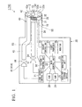
- FIG. 1 is a block diagram showing a constitution of the endoscope 1.
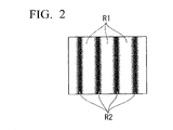
- FIG. 2 is a schematic view showing a light and shade pattern projected by the endoscope 1.
- the endoscope 1 is used in internal observation of the specimen, observation of the specimen disposed at a position that a conventional observation apparatus cannot easily access, or the like.
- the endoscope 1 includes a long insertion unit 10, and a main body section 20 to which a base end of the insertion unit 10 is connected.
- the insertion unit 10 is formed in a tubular shape.
- the insertion unit 10 is inserted into the specimen or an access path to the specimen.
- An image capturing unit 30, an illumination unit 40 and a pattern projection unit 50 are installed at the insertion unit 10.
- the image capturing unit 30 acquires an image of the specimen.
- the illumination unit 40 illuminates an observation field of vision in front of the insertion unit 10.
- the pattern projection unit 50 projects a light and shade pattern on the specimen.
- an opening 11, an illumination window 12 and a projection window 13 are installed at a tip surface 10a of the insertion unit 10. External light enters an object optical system 32 of the image capturing unit 30 through the opening 11.
- the illumination window 12 irradiates the illumination light from the illumination unit 40 to a forward side of the insertion unit.
- the projection window 13 irradiates the light and shade pattern from the pattern projection unit 50 to the forward side of the insertion unit.
- the pattern projection unit 50 projects the stripe pattern, which is a light and shade pattern, on the specimen.
- the image capturing unit 30 includes an imager 31, the object optical system 32 and a control unit 33.
- the imager 31 is disposed in the vicinity of the tip of the insertion unit 10.
- the object optical system 32 is disposed in front of the imager 31.
- the control unit 33 is connected to the imager 31.
- the object optical system 32 is disposed in the opening 11 of the insertion unit 10.
- the object optical system 32 has a predetermined angle of view.
- the object optical system 32 allows incidence of the reflective light in an observation field of vision defined by the angle of view into the imager 31, and forms an image of the specimen.
- the object optical system 32 has a cover member 32a having optical transparency. The cover member 32a seals the opening 11.
- the imager control unit 33 is installed in the main body section 20. In addition, the imager control unit 33 is connected to the imager 31 by a wiring 34 extending in the insertion unit 10. The imager control unit 33 performs various controls such as driving of the imager 31, setting of acquiring the video signal, and so on.
- the illumination unit 40 includes a first light source 41, an illumination optical system 42, a first fiber bundle 43 and a first incidence optical system 44.
- the first fiber bundle 43 guides light of the first light source 41 to the illumination optical system 42.
- the first incidence optical system 44 is disposed between the first light source 41 and the first fiber bundle 43.
- the first light source 41 is a light source configured to emit white light.
- the first light source 41 is disposed in the main body section 20.
- a known light source such as a halogen lamp, a mercury lamp, or the like, may be appropriately selected and employed as the first light source 41.
- the halogen lamp is employed as the first light source 41.
- the light emitted from the first light source 41 is illumination light configured to illuminate the specimen.
- the illumination optical system 42 is attached to the tip or the vicinity of the tip of the insertion unit 10.
- the illumination optical system 42 has a cover member 42a having optical transparency, and a lens group (not shown).
- the cover member 42a is installed in the illumination window 12 of the insertion unit 10.
- the illumination optical system 42 outputs the light radiated from the first light source 41 through the illumination window 12 to be spread to a field of vision range appropriate for the angle of view of the object optical system 32, and illuminates all over the observation field of vision.
- the first fiber bundle 43 extends from the vicinity of the illumination optical system 42 to the vicinity of the first light source 41 in the main body section 20 through the insertion unit 10.
- the kind of the first fiber bundle 43 is not particularly limited but a general light guide may be used.
- the first incidence optical system 44 converges the light emitted from the first light source 41 to substantially the same diameter as the first fiber bundle 43 and efficiently guides the light into the first fiber bundle 43.
- the pattern projection unit 50 includes a second light source 51, a projection optical system 52, a second fiber bundle 53, a second incidence optical system 54 and a pattern generating unit 55.
- the second fiber bundle 53 guides the light of the second light source 51 into the projection optical system 52.
- the second incidence optical system 54 is disposed between the second light source 51 and the second fiber bundle 53.
- the pattern generating unit 55 is disposed on an optical path of the light emitted from the second light source 51.
- the second light source 51 is a light source configured to emit light different from the first light source 41.
- the second light source 51 is disposed in the main body section 20.
- An LED light source, a laser light source, or the like, may be employed as the second light source 51.
- the LED light source is employed as the second light source 51.
- the light emitted from the second light source 51 is projection light configured to project the stripe pattern.
- the projection optical system 52 is attached to the tip or the vicinity of the tip of the insertion unit 10.
- the projection optical system 52 has a cover member 52a having optical transparency.
- the cover member 52a is disposed in the projection window 13 of the insertion unit 10.
- the cover member 52a installed at the projection window 13 may be configured in a lens shape.
- the projection optical system 52 spreads the light radiated from the second light source 51 to a field of vision range appropriate for the angle of view of the object optical system 32 and projects the light from the one projection window 13 into the field of vision.
- the second fiber bundle 53 extends from the vicinity of the projection optical system 52 to the vicinity of the second light source 51 in the main body section 20 through the insertion unit 10.
- a general light guide may be used as the second fiber bundle 53.
- the second incidence optical system 54 converges the light emitted from the second light source 51 to substantially the same diameter as the second fiber bundle 53 and efficiently guides the light into the second fiber bundle 53.
- the pattern generating unit 55 is configured to be formed in a stripe pattern.
- a slit plate having a plurality of slits, or a transparent plate formed of glass, resin, or the like, on which a stripe pattern is drawn may be used.
- the pattern generating unit 55 may use a liquid crystalline shutter module configured to switch penetration and non-penetration of the light to each element, a microelectromechanical system (MEMS) mirror module including a minute reflecting mirror installed at each element, or the like.
- MEMS microelectromechanical system
- the pattern generating unit 55 may use a liquid crystalline shutter module configured to switch penetration and non-penetration of the light to each element, a microelectromechanical system (MEMS) mirror module including a minute reflecting mirror installed at each element, or the like.
- MEMS microelectromechanical system
- the above-mentioned imager control unit 33, a light source control unit 21 and a main control unit 22 are installed in the main body section 20.
- the light source control unit 21 controls an operation of emitting illumination light from the illumination unit 40 and an operation of emitting projection light from the pattern projection unit 50.
- a video processor 27 and the main control unit 22 are connected to the imager control unit 33.
- the video processor 27 processes the video signal acquired by the imager 31.
- the main control unit 22 controls an operation of the imager control unit 33.
- the video processor 27 and the main control unit 22 are installed in the main body section 20.
- a monitor 28 is connected to the video processor 27.
- the monitor 28 displays the video signal processed by the video processor 27 as an image.
- the light source control unit 21 is connected to the first light source 41, the second light source 51 and the main control unit 21.
- the light source control unit 21 controls ON/OFF of the first light source 41 and the second light source 51 based on the control by the main control unit 22.
- the main control unit 22 is further connected to a manipulation unit 23, a RAM 24, a ROM 26, an auxiliary storage device 25, and the pattern control unit 56.
- the manipulation unit 23 has a switch or the like configured to allow a user to input various items into the endoscope 1.
- a touch panel installed to overlap a display screen of the monitor 28 may be employed as the manipulation unit 23.
- the RAM 24 functions as a work area used upon the image capturing of the specimen, measurement of the 3-dimensional shape, or the like, using the endoscope 1.
- firmware or the like is recorded on the ROM 26.
- the ROM 26 is configured to read the firmware or the like upon starting of the endoscope 1.
- the auxiliary storage device 25 may employ, for example, a storage device, a magnetic storage device, or the like, having a nonvolatile memory, which is rewritable.
- a time wa (see FIG. 4 ) from starting of emission of the illumination light from the first light source 41 to stabilization of light quantity of the illumination light and a time wb (see FIG 4 ) from starting of emission of the projection light from the second light source 51 to stabilization of light quantity of the projection light are previously stored in the main control unit 22.
- the first light source 41 is a halogen lamp and the second light source 51 is an LED light source
- a relation is set such that the time wa is longer than the time wb.
- the main control unit 22 first operates one of the illumination unit 40 and the pattern projection unit 50, which has a longer time until the light quantity is stabilized, based on the above-mentioned time wa and time wb.
- the other of the illumination unit 40 and the pattern projection unit 50, which has a shorter time until the light quantity is stabilized, is operated after that.
- the main control unit 22 acquires an image of the specimen in a state in which the illumination light is radiated (hereinafter referred to as a "bright field image”) and an image of the specimen in a state in which the stripe pattern is projected by the projection light (hereinafter referred to as a "pattern projection image") at the image capturing unit 30 by controlling the imager control unit 33.
- a first image is an image in which the bright field image is acquired first.
- a second image is an image in which the pattern projection image is acquired after that.
- the main control unit 22 includes a blur detection unit configured to select at least two images from the bright field image and the pattern projection image and detect a blur between the insertion unit 10 and the specimen based on a deviation amount of the selected two images.
- a threshold value of the deviation amount allowed in the two images is previously stored in the blur detection unit.
- the blur detection unit detects the deviation amount in the two images by a known unit. When the deviation amount in the two images exceeds the threshold value, the blur detection unit determines that there is a relative movement (hereinafter referred to as a "blur") between the insertion unit 10 and the specimen.
- a relative movement hereinafter referred to as a "blur"
- the main control unit 22 is configured such that a measuring program of measuring a 3-dimensional shape of the specimen can be operated using the pattern projection image.
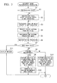
- FIG 3 is a flowchart for describing an operation in use of the endoscope 1.
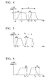
- FIG 4 is a graph showing a relation between a light quantity and a time in use of the endoscope 1.
- the image acquisition method of the embodiment is a method including irradiating the specimen with illumination light and acquiring an image of a specimen using the endoscope, and projecting a stripe pattern on the specimen using projection light and acquiring the image of the specimen.
- the endoscope 1 of the embodiment can measure the 3-dimensional shape of the specimen using the obtained image.
- a user inserts the insertion unit 10 into the specimen or an access path to the specimen, for example, a conduit line, or the like, and moves the tip of the insertion unit 10 forward to a predetermined observation area.
- the user performs inspection or the like of the specimen by switching an observation mode of observing a predetermined area of the specimen and a measuring mode of measuring a 3-dimensional shape of the observation area according to necessity.
- the light source control unit 21 receives an instruction of the main control unit 22, turns the first light source 41 on, and turns the second light source 51 off.
- the stripe pattern is not projected from the pattern projection unit 50, and white light is radiated from the illumination unit 40 to the observation field of vision so that the observation field of vision is illuminated (hereinafter, this illumination state is referred to as an "observation state").
- An image of the illuminated specimen is imaged on the imager 31 through the object optical system 32.
- a video signal transmitted from the imager 31 is processed in the video processor 27 and displayed on the monitor 28. The user can observe the specimen by the image of the specimen displayed on the monitor 28, and store the image according to necessity.
- the user When the observation mode is switched to the measuring mode, the user inputs an instruction of switching the mode.
- the instruction of switching the observation mode to the measuring mode is input by the user, measuring image photographing (see FIG 3 ) is started in the main control unit 22.
- step S1 it is determined whether the endoscope 1 is in the observation state or not (step S1 shown in FIG. 3 ).
- step S1 when it is determined that the endoscope 1 is in the observation state, step S3 is performed.
- step S2 is performed.
- step S1 is terminated.
- Step S2 is a step of switching the endoscope 1 to the observation state.
- step S2 the first light source 41 is turned on and the second light source 51 is turned off. Accordingly, the stripe pattern from the pattern projection unit 50 is not projected and the white light is radiated from the illumination unit 40 to the observation field of vision so that the observation field of vision is illuminated.
- the light quantity of the first light source 41 is increased, and the light quantity of the first light source 41 at the time t a1 is stabilized.
- the bright field image can be acquired after the time t a1 in which the light quantity of the first light source 41 is stabilized.
- step S2 is terminated, and step S3 is performed.
- Step S3 is a step of photographing the image of the specimen illuminated by the illumination light from the illumination unit 40.
- the stripe pattern is not projected.
- step S3 an image (a bright field image) is acquired by the imager 31 of the image capturing unit 30 in a state in which the specimen is illuminated by the illumination light from the illumination unit 40.
- the bright field image photographed in step S3 is temporarily stored in the RAM 24.
- step S3 is terminated, and step S4 is performed.
- Step S4 is a step of projecting the stripe pattern on the specimen.
- step S4 based on the instruction of the main control unit 22, the first light source 41 is turned off and the second light source 51 is turned on.
- the second light source 51 is turned on at a time t b0 in step S4, the light quantity of the second light source 51 is increased and the light quantity of the second light source 51 at a time t b1 is stabilized.
- the pattern projection image can be acquired after the time t b1 in which the light quantity of the second light source 51 is stabilized.
- the stripe pattern projected on the specimen becomes a pattern in which bright sections R1 by the white light source and dark sections R2 shaded by the stripe pattern generating unit 55 are alternately arranged.
- this state becomes a state in which an appropriate stripe is projected on the specimen from one place (hereinafter, this state is referred to as a "pattern projection state").
- time wa and the time wb shown in FIG. 4 are described as times until arriving at a stable state in which a light quantity of the illumination light or the projection light becomes constant, the time wa and the time wb may be times until arriving at the light quantity needed to acquire the image while the light quantity has yet to arrive at the stable state.
- a time we from stoppage of the first light source 41 that emits illumination light or starting of blocking of the illumination light until the light quantity of the illumination light is reduced to a light quantity that does not exert an influence on image acquisition and a time wf from stoppage of the second light source 51 that emits the projection light or starting of the blocking of the projection light until the light quantity of the projection light is reduced to a light quantity does not exert an influence on image acquisition may be previously stored in the main control unit 22.
- the main control unit 22 is operated based on the above-mentioned time we and time wf.
- the main control unit 22 first operates one of the illumination unit 40 and the pattern projection unit 50, which has a short time until the light quantity is reduced to the light quantity having no influence to acquire the image.
- the main control unit 22 operates the other of the illumination unit 40 and the pattern projection unit 50 after that, which has a long time until the light quantity is reduced to the light quantity having no influence to acquire the image.
- the main control unit 22 may first operate the illumination unit 40 and then operate the pattern projection unit 50.
- the total time D3 is a time in which a time from stoppage of the first light source 41 that emits illumination light or starting of blocking of the illumination light until the light quantity of the illumination light is reduced to a light quantity that does not exert an influence on acquiring the image and a time from starting of emission of the illumination light from the second light source 51 to arrival at the light quantity at which the light quantity of the illumination light is needed to acquire the image are added.
- the total time D4 is a time in which a time from stoppage of the second light source 51 that emits projection light or starting of blocking of the projection light until the light quantity of the projection light is reduced to a light quantity that does not exert an influence on acquiring the image and a time from starting of emission of the illumination light from the first light source 41 to arrival at the light quantity at which the light quantity of the illumination light is needed to acquire the image are added.
- the main control unit 22 first operates the pattern projection unit 50 and then operates the illumination unit 40.
- FIG 4 or 6 shows an example in which the first light source 41 is completely turned off and then the second light source 51 is turned on. According to necessity, as the stoppage or blocking of the first light source 41 is started, turning on of the second light source 51 is immediately started, and a period in which the light quantity of the first light source 41 is reduced may overlap a period in which the light quantity of the second light source 51 is increased.
- step S5 a time from the time t a1 at which acquisition of a first image is started until acquisition of a second image is terminated in step S5 (to be described below) may be further reduced.
- step S4 is terminated and step S5 is performed.
- Step S5 is a step of photographing a pattern projection image in the pattern projection state.
- step S5 the stripe pattern projected on the specimen becomes a pattern varied according to the 3-dimensional shape of the specimen.
- one image is acquired by the imager 31 of the image capturing unit 30 (hereinafter, an image photographed in the pattern projection state is referred to as a "pattern projection image").
- the pattern projection image photographed in step S5 is temporarily stored on the RAM 24.
- step S5 is terminated and step S6 is performed.
- a time length D1 from the time t a1 at which acquisition of the bright field image is started in step S3 to the time t b2 at which acquisition of the pattern projection image is terminated in step S5 includes the time wb from starting of turning on of the second light source 51 until the light quantity of the second light source 51 is stabilized.
- the time wb is shorter than the time wa from starting of turning on of the first light source 41 until the light quantity of the first light source 41 is stabilized. For this reason, in the case of the embodiment, as the second light source 51 is turned on after the first light source 41, an interval in which the two images (the bright field image and the pattern projection image) are acquired becomes shorter than that of the case in which the first light source 41 is turned on after the second light source 51.
- step S2 to step S5 the bright field image of the specimen is acquired using the illumination light having a longer time until the light quantity is stabilized, based on the time wa from starting of emission of the illumination light until the light quantity of the illumination light is stabilized and the time wb from starting of emission of the projection light until the light quantity of the projection light is stabilized.
- step S2 to step S5 the pattern projection image of the specimen is acquired using the projection light having a short time until the light quantity is stabilized.
- Step S6 is a step of detecting a blur between the insertion unit 10 and the test object from step S2 to step S5 based on the images (the bright field image and the pattern projection image) photographed from step S2 to step S5.
- step S6 first, the same feature point is detected from the bright field image and the pattern projection image stored on the RAM 24, and coordinates of the feature point in the two images are calculated.
- step S6 is terminated and step S7 is performed.
- Step S7 is a step of determining a blur of the two images using the feature point detected in step S6 and diverging the processing.
- step S7 when the coordinates of the feature point in the two images are the same coordinates in each of the images, it is determined that the blur is not generated from the initial image and the after-image, and step S8 is performed.
- step S8 when the coordinates of the feature point in the two images are different coordinates in the images, it is determined that a blur is generated from the initial image and the after-image, a message showing that photographing is necessary again since the blur is generated is displayed on the monitor 28 (step S11), and a series of processing is terminated.
- step S7 is terminated.
- Step S8 is a step of allowing a user to select whether 3-dimensional measurement using the photographed pattern projection image is performed now or later.
- step S8 for example, inquiries such as "Perform measurement?" and so on are displayed on the monitor 28, and an input of determining whether the 3-dimensional measurement using the photographed pattern projection image is performed or not is prompted to the user.
- step S9 is performed.
- step S12 is performed.
- step S8 is terminated.
- Step S9 is a step of performing analysis for 3-dimensional measurement.
- step S9 analysis for a 3-dimensional shape is performed based on the pattern projection image stored on the RAM 24.
- the 3-dimensional shape of the specimen is analyzed by, for example, a known spatial phase shift method or Fourier transform method using one pattern projection image.
- step S9 may be performed as background processing of step S8 simultaneously with starting of step S8.
- step S9 is terminated and step S10 is performed.
- Step S 10 is a step of transferring a display on the monitor 28 to the screen of various measuring modes and displaying a measurement result on the monitor 28 using information stored in step S10.
- step S10 the 3-dimensional shape of the specimen displayed on the bright field image is displayed on the monitor 28, while overlay-displaying a result analyzed in step S9 on the bright field image acquired in step S3, and so on. Accordingly, the user can perceive the 3-dimensional shape of the specimen.
- step S10 is terminated and a series of processing is terminated.
- Step S12 is a step diverged from step S8, and a step of performing information processing needed for performing display of the measurement result after that.
- step S12 like step S9, based on the pattern projection image stored on the RAM 24, analysis of the 3-dimensional shape is performed.
- the 3-dimensional shape of the specimen is analyzed by, for example, a known spatial phase shift method or Fourier transform method using one pattern projection image.
- the bright field image, the pattern projection image, the analysis result of the 3-dimensional shape, and optical parameters used for analysis are saved in the auxiliary storage device 25 as binary files or text files.
- these files are saved in the auxiliary storage device 25 to be read in a lump after that.
- step S12 is terminated and a series of processing is terminated.
- the endoscope 1 and the image acquisition method of the embodiment based on the time wa and the time wb until the light quantities of the first light source 41 and the second light source 51 are stabilized, acquisition of the bright field image using the first light source 41 having a long time until the light quantity is stabilized is performed first, and after the bright field image is acquired, the pattern projection image is acquired. For this reason, the interval of acquiring the bright field image and the pattern projection image can be reduced. Accordingly, a positional deviation between the plurality of acquired images can be suppressed.
- the time from starting of acquisition of the image of the specimen to termination of acquisition of the image of the specimen can be reduced.
- FIG 5 is a graph showing a relation between a light quantity and a time in use of an endoscope 1A of the variant.
- the endoscope 1A (see FIG. 1 ) of the variant is distinguished from the above-mentioned endoscope 1 in that a first light source 41A having a shutter module is installed instead of the first light source 41.
- an operation of the main control unit 22 is different from that of the above-mentioned endoscope 1.
- the shutter module of the first light source 41 A is a shutter, an opening/closing operation of which is controlled by the light source control unit 21.
- the first light source 41 A is turned on while the endoscope 1 A is on.
- the first light source 41 A as the shutter module is opened and closed, ON and OFF of the illumination light and the emission light quantity are adjusted according to control from the light source control unit 21.
- the light source control unit 21 configured to control the first light source 41A may have a power-saving circuit configured to turn off the first light source 41A when there is no need to image the bright field image.
- a time wd (see FIG 5 ) from starting of emission of the illumination light from the first light source 41A having the shutter module until the light quantity of the illumination light is stabilized is a time from an opening operation of the shutter of the first light source 41A to complete opening of the shutter.
- the time wd is shorter than a time wc (in the variant, having the same length as the time wb shown in FIG 4 ) from starting of emission of the projection light from the second light source 51 until the light quantity of the projection light is stabilized.
- the main control unit 22 first operates the pattern projection unit 50 having a long time until the light quantity is stabilized. In addition, in the illumination unit 40 and the pattern projection unit 50, the main control unit 22 later operates the illumination unit 40 having a short time until the light quantity is stabilized. Further, the main control unit 22 first acquires the stripe image with respect to the image capturing unit 30, and then acquires the bright field image after the pattern projection image is acquired.
- a time length D2 from a time t c1 at which acquisition of the pattern projection image is started to a time t d2 at which acquisition of the bright field image is terminated includes a time wd from an opening operation of the shutter of the first light source 41A to the complete opening of the shutter.
- the time wd is shorter than a time wc from starting of turning on of the second light source 51 until the light quantity of the second light source 52 is stabilized. For this reason, in the case of the variant, as the first light source 41A is turned on after the second light source 51, an interval of acquiring the two images (the bright field image and the pattern projection image) is smaller than the case in which the second light source 51 is turned on after the first light source 41 A.
- the time wd from starting of emission of the light from the first light source 41A to stabilization of the light quantity of the first light source 41A depends on the time in which the shutter is opened and closed, rather than the time until the light quantity of the light source is stabilized. For this reason, the light source having a time applied until the light quantity is stabilized, and a selection degree of freedom of the light source is increased.
- the main control unit is configured such that the pattern projection image is acquired first and the bright field image is acquired after that.
- the shutter module may be installed at the second light source. Further, the shutter modules may be installed at both of the first light source and the second light source.
- the endoscope configured such that the stripe pattern is projected from one place of the tip surface of the insertion unit
- the endoscope may be configured such that stripe patterns having different phases are projected from a plurality of places of the tip surface of the insertion unit. Even in this case, the same effects as described in the above-mentioned embodiment and variant is exhibited.
- a plurality of illumination windows may be opened at the tip surface of the insertion unit.
- analysis of the 3-dimensional shape may be performed by a time phase shift method of projecting a plurality of stripe patterns having different phases on the specimen and acquiring a plurality of pattern projection images having different phases.
- the bright field image may be acquired again.
- a blur can be detected using the bright field image acquired before and after the pattern projection image is acquired.
- pluralities of pattern projection images and bright field images may be acquired, and an optimal image may be appropriately selected to analyze the 3-dimensional shape and detect the blur.
- the light quantity needed to acquire the bright field image and the light quantity needed to acquire the pattern projection image may be different from each other.
- the light quantity emitted from the first light source and the light quantity emitted from the second light source may be different from each other.
- the positional deviation between the acquired images can be suppressed.
Landscapes
- Health & Medical Sciences (AREA)
- Life Sciences & Earth Sciences (AREA)
- Surgery (AREA)
- Engineering & Computer Science (AREA)
- Veterinary Medicine (AREA)
- Public Health (AREA)
- Biophysics (AREA)
- General Health & Medical Sciences (AREA)
- Pathology (AREA)
- Animal Behavior & Ethology (AREA)
- Physics & Mathematics (AREA)
- Biomedical Technology (AREA)
- Heart & Thoracic Surgery (AREA)
- Medical Informatics (AREA)
- Molecular Biology (AREA)
- Radiology & Medical Imaging (AREA)
- Optics & Photonics (AREA)
- Nuclear Medicine, Radiotherapy & Molecular Imaging (AREA)
- Dentistry (AREA)
- Oral & Maxillofacial Surgery (AREA)
- Signal Processing (AREA)
- Endoscopes (AREA)
- Length Measuring Devices By Optical Means (AREA)
- Instruments For Viewing The Inside Of Hollow Bodies (AREA)
Claims (11)
- Endoscope configuré pour mesurer un spécimen en utilisant une image de projection de motif du spécimen sur lequel un motif de lumière et d'ombre de la lumière est projeté, l'endoscope comprenant :une unité d'insertion (10) ;une unité de capture d'image (31) installée au niveau d'une section de pointe de l'unité d'insertion et configurée pour acquérir une image du spécimen ;une unité d'éclairage (40) comportant une première source de lumière (41) configurée pour émettre une lumière d'éclairage pour éclairer un champ de vision d'observation de l'unité de capture d'image ;une unité de projection de motif (50) comportant une deuxième source de lumière (51) configurée pour émettre une lumière de projection pour projeter le motif de lumière et d'ombre sur le spécimen ; etune unité de commande (22) configurée pour commander une opération consistant à acquérir l'image par l'unité de capture d'image, une opération consistant à émettre la lumière d'éclairage depuis l'unité d'éclairage, et une opération consistant à émettre la lumière de projection depuis l'unité de projection de motif,caractérisé en ce que dans l'unité de commande,sur la base d'un temps (Wa) allant du début de l'émission de la lumière d'éclairage depuis la première source de lumière jusqu'à ce que la quantité de lumière de la lumière d'éclairage atteigne un niveau de quantité de lumière nécessaire pour acquérir l'image, et d'un temps (Wb) allant du début de l'émission de la lumière de projection depuis la deuxième source de lumière jusqu'à ce qu'une quantité de lumière de la lumière de projection atteigne un niveau de quantité de lumière nécessaire pour acquérir l'image,l'une parmi l'unité d'éclairage et l'unité de projection de motif, qui nécessite un temps long pour que la quantité de lumière atteigne le niveau de quantité de lumière nécessaire pour acquérir l'image, est actionnée en premier de sorte qu'une première image du spécimen est acquise par l'unité de capture d'image, etl'autre parmi l'unité d'éclairage et l'unité de projection de motif, qui nécessite un temps court pour que la quantité de lumière atteigne le niveau de quantité de lumière nécessaire pour acquérir l'image, est actionnée après l'acquisition de la première image de sorte qu'une deuxième image du spécimen est acquise par l'unité de capture d'image.
- Endoscope selon la revendication 1, dans lequel, dans l'unité de commande,
sur la base d'un temps allant du début de la coupure de la lumière d'éclairage jusqu'à ce que la quantité de lumière de la lumière d'éclairage soit réduite à une quantité de lumière qui n'exerce aucune influence sur l'acquisition de l'image, et d'un temps allant du début de la coupure de la lumière de projection jusqu'à ce que la quantité de lumière de la lumière de projection soit réduite à une quantité de lumière qui n'exerce aucune influence sur l'acquisition de l'image,
l'une parmi l'unité d'éclairage et l'unité de projection de motif, qui nécessite un temps court pour que la quantité de lumière soit réduite à une quantité de lumière qui n'exerce aucune influence sur l'acquisition de l'image, est actionnée en premier de sorte que la première image du spécimen est acquise par l'unité de capture d'image, et
l'autre parmi l'unité d'éclairage et l'unité de projection de motif, qui nécessite un temps long pour que la quantité de lumière soit réduite à une quantité de lumière qui n'exerce aucune influence sur l'acquisition de l'image, est actionnée après l'acquisition de la première image de sorte que la deuxième image du spécimen est acquise par l'unité de capture d'image. - Endoscope selon la revendication 1, dans lequel, dans l'unité de commande,
lorsqu'un temps total d'un temps allant du début de la coupure de la lumière d'éclairage jusqu'à ce que la quantité de lumière de la lumière d'éclairage soit réduite à une quantité de lumière qui n'exerce aucune influence sur l'acquisition de l'image, et d'un temps allant du début de l'émission de la lumière d'éclairage depuis la deuxième source de lumière jusqu'à ce que la quantité de lumière de la lumière d'éclairage atteigne une quantité de lumière nécessaire pour acquérir l'image est plus court qu'un temps total d'un temps allant du début de la coupure de la lumière de projection jusqu'à ce que la quantité de lumière de la lumière de projection soit réduite à une quantité de lumière qui n'exerce aucune influence sur l'acquisition de l'image, et d'un temps allant du début de l'émission de la lumière d'éclairage depuis la première source de lumière jusqu'à ce que la quantité de lumière de la lumière d'éclairage atteigne une quantité de lumière nécessaire pour acquérir l'image,
l'unité d'éclairage est actionnée en premier de sorte que la première image du spécimen est acquise par l'unité de capture d'image, et ensuite l'unité de projection de motif est actionnée de sorte que la deuxième image du spécimen est acquise par l'unité de capture d'image. - Endoscope selon la revendication 1, dans lequel, dans l'unité de commande,
lorsqu'un temps total d'un temps allant du début de la coupure de la lumière d'éclairage jusqu'à ce que la quantité de lumière de la lumière d'éclairage soit réduite à une quantité de lumière qui n'exerce aucune influence sur l'acquisition de l'image, et d'un temps allant du début de l'émission de la lumière d'éclairage depuis la deuxième source de lumière jusqu'à ce que la quantité de lumière de la lumière d'éclairage atteigne une quantité de lumière nécessaire pour acquérir l'image est plus long qu'un temps total d'un temps allant du début de la coupure de la lumière de projection jusqu'à ce que la quantité de lumière de la lumière de projection soit réduite à une quantité de lumière qui n'exerce aucune influence sur l'acquisition de l'image, et d'un temps allant du début de l'émission de la lumière d'éclairage depuis la première source de lumière jusqu'à ce que la quantité de lumière de la lumière d'éclairage atteigne une quantité de lumière nécessaire pour acquérir l'image,
l'unité de projection de motif est actionnée en premier de sorte que la première image du spécimen est acquise par l'unité de capture d'image, et ensuite l'unité d'éclairage est actionnée de sorte que la deuxième image du spécimen est acquise par l'unité de capture d'image. - Endoscope selon l'une quelconque des revendications 2 à 4, dans lequel la coupure de la lumière d'éclairage comprend la coupure de la première source de lumière qui émet la lumière d'éclairage.
- Endoscope selon l'une quelconque des revendications 2 à 4, dans lequel la coupure de la lumière d'éclairage comprend le blocage de la lumière d'éclairage.
- Endoscope selon l'une quelconque des revendications 2 à 4, dans lequel la coupure de la lumière de projection comprend la coupure de la deuxième source de lumière qui émet la lumière de projection.
- Endoscope selon l'une quelconque des revendications 2 à 4, dans lequel la coupure de la lumière de projection comprend le blocage de la lumière de projection.
- Endoscope selon l'une quelconque des revendications 1 à 8, dans lequel un obturateur configuré pour commuter un état d'émission de lumière est installé au niveau d'au moins l'une parmi la première source de lumière et la deuxième source de lumière.
- Endoscope selon l'une quelconque des revendications 1 à 9, dans lequel l'unité de commande comprend une unité de détection de flou configurée pour sélectionner au moins deux images à partir de l'image du spécimen acquise dans un état dans lequel la lumière d'éclairage est rayonnée et de l'image du spécimen acquise dans un état dans lequel la lumière de projection est rayonnée, et détecter un flou de l'unité d'insertion et du spécimen sur la base d'une quantité de déviation des deux images.
- Procédé d'acquisition d'image consistant à rayonner une lumière d'éclairage sur un spécimen pour acquérir une image du spécimen et à projeter un motif en bande sur le spécimen pour acquérir une image du spécimen en utilisant une lumière de projection, en utilisant un endoscope selon la revendication 1, le procédé d'acquisition d'image comprenant les étapes consistant à :sur la base d'un temps allant du début de l'émission de la lumière d'éclairage jusqu'à ce qu'une quantité de lumière de la lumière d'éclairage atteigne une quantité de lumière nécessaire pour acquérir l'image, et d'un temps allant du début de l'émission de la lumière de projection jusqu'à ce qu'une quantité de lumière de la lumière de projection atteigne une quantité de lumière nécessaire pour acquérir l'image,acquérir une première image du spécimen en utilisant l'une parmi la lumière d'éclairage et la lumière de projection nécessitant un temps long pour que la quantité de lumière soit stabilisée ; etacquérir une deuxième image du spécimen en utilisant l'autre parmi la lumière d'éclairage et la lumière de projection nécessitant un temps court pour que la quantité de lumière atteigne une quantité de lumière nécessaire pour acquérir l'image, après que la première image a été acquise.
Applications Claiming Priority (2)
| Application Number | Priority Date | Filing Date | Title |
|---|---|---|---|
| JP2011116091A JP5841353B2 (ja) | 2011-05-24 | 2011-05-24 | 内視鏡装置および画像取得方法 |
| PCT/JP2012/063271 WO2012161246A1 (fr) | 2011-05-24 | 2012-05-24 | Endoscope et procédé d'acquisition d'image |
Publications (3)
| Publication Number | Publication Date |
|---|---|
| EP2700347A1 EP2700347A1 (fr) | 2014-02-26 |
| EP2700347A4 EP2700347A4 (fr) | 2014-04-16 |
| EP2700347B1 true EP2700347B1 (fr) | 2015-08-19 |
Family
ID=47217319
Family Applications (1)
| Application Number | Title | Priority Date | Filing Date |
|---|---|---|---|
| EP12788847.7A Not-in-force EP2700347B1 (fr) | 2011-05-24 | 2012-05-24 | Endoscope et procédé d'acquisition d'image |
Country Status (4)
| Country | Link |
|---|---|
| US (1) | US9451872B2 (fr) |
| EP (1) | EP2700347B1 (fr) |
| JP (1) | JP5841353B2 (fr) |
| WO (1) | WO2012161246A1 (fr) |
Families Citing this family (30)
| Publication number | Priority date | Publication date | Assignee | Title |
|---|---|---|---|---|
| CN104955418B (zh) | 2012-12-24 | 2017-10-13 | 牙医技术G·P·L·有限公司 | 用在龈下测量的装置及方法 |
| JP2015129715A (ja) * | 2014-01-08 | 2015-07-16 | リコーエレメックス株式会社 | 検査装置及び検査装置の制御方法 |
| CN106028930B (zh) | 2014-02-21 | 2021-10-22 | 3D集成公司 | 包括手术器械的套件 |
| WO2016020966A1 (fr) * | 2014-08-04 | 2016-02-11 | 株式会社ニコン | Procédé de détection, procédé de mesure de forme, dispositif de mesure de forme, procédé de fabrication de structure, système de fabrication de structure et programme de mesure de forme |
| WO2016113745A1 (fr) * | 2015-01-18 | 2016-07-21 | Dentlytec G.P.L. Ltd | Système, dispositif et procédé d'exploration dentaire intra-orale |
| US12259231B2 (en) | 2015-01-18 | 2025-03-25 | Dentlytec G.P.L. Ltd. | Intraoral scanner |
| WO2017125926A2 (fr) * | 2016-01-18 | 2017-07-27 | Dentlytec G.P.L. Ltd | Scanner intraoral |
| WO2016178212A1 (fr) | 2015-05-01 | 2016-11-10 | Dentlytec G.P.L. Ltd | Système, dispositif et procédés pour empreintes dentaires numériques |
| EP3316019A4 (fr) * | 2015-06-25 | 2019-03-06 | Olympus Corporation | Dispositif à endoscope |
| CN108024806B (zh) | 2015-07-21 | 2022-07-01 | 3D集成公司 | 套管组装套件、套管针组装套件、套筒组件、微创手术系统及其方法 |
| US11020144B2 (en) | 2015-07-21 | 2021-06-01 | 3Dintegrated Aps | Minimally invasive surgery system |
| DK178899B1 (en) | 2015-10-09 | 2017-05-08 | 3Dintegrated Aps | A depiction system |
| JP6687877B2 (ja) * | 2015-10-14 | 2020-04-28 | 凸版印刷株式会社 | 撮像装置及びそれを用いた内視鏡装置 |
| WO2017216803A1 (fr) | 2016-06-16 | 2017-12-21 | Safesac Medical Ltd. | Dispositif de confinement de tissu destiné à être utilisé dans des interventions chirurgicales |
| US11690604B2 (en) | 2016-09-10 | 2023-07-04 | Ark Surgical Ltd. | Laparoscopic workspace device |
| US12285188B2 (en) | 2016-09-10 | 2025-04-29 | Ark Surgical Ltd. | Laparoscopic workspace device |
| EP3648703B1 (fr) | 2017-07-04 | 2023-04-26 | Dentlytec G.P.L. Ltd. | Scanner dentaire avec élément capteur ultrasonique pour améliorer les données optiques |
| WO2019021285A1 (fr) | 2017-07-26 | 2019-01-31 | Dentlytec G.P.L. Ltd | Scanner intra-buccal |
| JP7134759B2 (ja) * | 2018-07-13 | 2022-09-12 | ソニー・オリンパスメディカルソリューションズ株式会社 | 医療用画像処理装置及び医療用観察システム |
| ES3037621T3 (en) | 2018-07-19 | 2025-10-03 | Activ Surgical Inc | Systems and methods for multi-modal sensing of depth in vision systems for automated surgical robots |
| CN113993474A (zh) | 2018-12-28 | 2022-01-28 | 艾科缇弗外科公司 | 在微创手术中优化可达性、工作空间和灵巧性的系统和方法 |
| CN113853151A (zh) | 2018-12-28 | 2021-12-28 | 艾科缇弗外科公司 | 用于在手术期间定向远程相机的用户界面元件 |
| US12491058B2 (en) | 2019-01-09 | 2025-12-09 | Dentlytec G.P.L. Ltd. | Dental device with probe and methods associated therewith |
| US12292564B2 (en) | 2019-04-08 | 2025-05-06 | Activ Surgical, Inc. | Systems and methods for medical imaging |
| CN113950279B (zh) | 2019-04-08 | 2023-04-14 | 艾科缇弗外科公司 | 用于医疗成像的系统和方法 |
| WO2020214821A1 (fr) | 2019-04-19 | 2020-10-22 | Activ Surgical, Inc. | Systèmes et procédés pour cinématiques de trocart |
| CN114599263A (zh) | 2019-08-21 | 2022-06-07 | 艾科缇弗外科公司 | 用于医疗成像的系统和方法 |
| WO2021172131A1 (fr) * | 2020-02-28 | 2021-09-02 | 富士フイルム株式会社 | Système d'endoscope et procédé de fonctionnement de système d'endoscope |
| EP4120000B1 (fr) * | 2020-03-13 | 2026-02-18 | FUJIFILM Corporation | Système d'endoscope et procédé de fonctionnement de système d'endoscope |
| WO2022130385A2 (fr) | 2020-12-17 | 2022-06-23 | Ark Surgical Ltd. | Dispositif de confinement de tissu laparoscopique |
Family Cites Families (11)
| Publication number | Priority date | Publication date | Assignee | Title |
|---|---|---|---|---|
| JPH03128043A (ja) * | 1989-10-16 | 1991-05-31 | Toshiba Corp | 形状計測内視鏡装置 |
| JP3126065B2 (ja) * | 1991-12-09 | 2001-01-22 | オリンパス光学工業株式会社 | 計測用内視鏡装置 |
| JPH0961132A (ja) * | 1995-08-28 | 1997-03-07 | Olympus Optical Co Ltd | 3次元形状計測装置 |
| DE19636354A1 (de) * | 1996-09-02 | 1998-03-05 | Ruedger Dipl Ing Rubbert | Verfahren und Vorrichtung zur Durchführung von optischen Aufnahmen |
| JP4229791B2 (ja) * | 2003-09-19 | 2009-02-25 | 真 金子 | 内視鏡装置 |
| JP2009061014A (ja) * | 2007-09-05 | 2009-03-26 | Fujifilm Corp | 硬さ測定装置、硬さ測定方法、および内視鏡システム |
| US7821649B2 (en) | 2008-03-05 | 2010-10-26 | Ge Inspection Technologies, Lp | Fringe projection system and method for a probe suitable for phase-shift analysis |
| JP2009240621A (ja) * | 2008-03-31 | 2009-10-22 | Hoya Corp | 内視鏡装置 |
| US20100268069A1 (en) * | 2009-04-16 | 2010-10-21 | Rongguang Liang | Dental surface imaging using polarized fringe projection |
| JP5583761B2 (ja) * | 2009-06-01 | 2014-09-03 | ホスラー ゲルト | 動的基準フレームを用いた3次元表面検出方法及び装置 |
| JP2011229850A (ja) * | 2010-04-30 | 2011-11-17 | Fujifilm Corp | 内視鏡装置、方法およびプログラム |
-
2011
- 2011-05-24 JP JP2011116091A patent/JP5841353B2/ja not_active Expired - Fee Related
-
2012
- 2012-05-24 EP EP12788847.7A patent/EP2700347B1/fr not_active Not-in-force
- 2012-05-24 WO PCT/JP2012/063271 patent/WO2012161246A1/fr not_active Ceased
-
2013
- 2013-11-13 US US14/079,357 patent/US9451872B2/en not_active Expired - Fee Related
Also Published As
| Publication number | Publication date |
|---|---|
| US20140066784A1 (en) | 2014-03-06 |
| EP2700347A4 (fr) | 2014-04-16 |
| JP2012239829A (ja) | 2012-12-10 |
| EP2700347A1 (fr) | 2014-02-26 |
| WO2012161246A1 (fr) | 2012-11-29 |
| JP5841353B2 (ja) | 2016-01-13 |
| US9451872B2 (en) | 2016-09-27 |
Similar Documents
| Publication | Publication Date | Title |
|---|---|---|
| EP2700347B1 (fr) | Endoscope et procédé d'acquisition d'image | |
| US10898110B2 (en) | Endoscope apparatus and measuring method | |
| US9581802B2 (en) | Endoscope device, and measurement method | |
| EP2700348B1 (fr) | Endoscope | |
| US8747305B2 (en) | Endoscope system and endoscopic observation method | |
| EP2543308A1 (fr) | Dispositif d'observation de fluorescence | |
| KR970706485A (ko) | 광 투사 농도 측정 방법 및 그의 측정장치(method and apparatus for measuring light projection concentration) | |
| EP3248528A1 (fr) | Système d'endoscope | |
| WO2012137845A1 (fr) | Dispositif d'observation dans lequel la détection de position d'extrémité de pointe de section d'insertion en utilisant une lumière externe est possible | |
| US20190104921A1 (en) | Endoscopic system | |
| US20120062724A1 (en) | Endoscope apparatus | |
| JP6032870B2 (ja) | 計測方法 | |
| JP6451833B2 (ja) | 顕微鏡装置、観察方法、及び制御プログラム | |
| JP5893264B2 (ja) | 内視鏡装置 | |
| CN103799964B (zh) | 眼科装置和眼科摄像方法 | |
| CN100510619C (zh) | 测量仪 | |
| JP2009222607A (ja) | 試料分析装置の照明制御方法および試料分析装置 | |
| US20090034062A1 (en) | Confocal microscope | |
| JP2008125989A (ja) | 内視鏡ポイント光照射位置調整システム | |
| JP3650143B2 (ja) | 顕微鏡写真撮影装置 | |
| JPH10221068A (ja) | 電子レベル | |
| JP2012130573A (ja) | ホワイトバランス調整システムおよび内視鏡プロセッサ |
Legal Events
| Date | Code | Title | Description |
|---|---|---|---|
| PUAI | Public reference made under article 153(3) epc to a published international application that has entered the european phase |
Free format text: ORIGINAL CODE: 0009012 |
|
| 17P | Request for examination filed |
Effective date: 20131119 |
|
| AK | Designated contracting states |
Kind code of ref document: A1 Designated state(s): AL AT BE BG CH CY CZ DE DK EE ES FI FR GB GR HR HU IE IS IT LI LT LU LV MC MK MT NL NO PL PT RO RS SE SI SK SM TR |
|
| A4 | Supplementary search report drawn up and despatched |
Effective date: 20140313 |
|
| RIC1 | Information provided on ipc code assigned before grant |
Ipc: A61B 1/04 20060101ALI20140307BHEP Ipc: A61B 1/00 20060101AFI20140307BHEP |
|
| DAX | Request for extension of the european patent (deleted) | ||
| GRAP | Despatch of communication of intention to grant a patent |
Free format text: ORIGINAL CODE: EPIDOSNIGR1 |
|
| INTG | Intention to grant announced |
Effective date: 20150320 |
|
| RAP1 | Party data changed (applicant data changed or rights of an application transferred) |
Owner name: OLYMPUS CORPORATION |
|
| GRAS | Grant fee paid |
Free format text: ORIGINAL CODE: EPIDOSNIGR3 |
|
| GRAA | (expected) grant |
Free format text: ORIGINAL CODE: 0009210 |
|
| AK | Designated contracting states |
Kind code of ref document: B1 Designated state(s): AL AT BE BG CH CY CZ DE DK EE ES FI FR GB GR HR HU IE IS IT LI LT LU LV MC MK MT NL NO PL PT RO RS SE SI SK SM TR |
|
| REG | Reference to a national code |
Ref country code: GB Ref legal event code: FG4D |
|
| REG | Reference to a national code |
Ref country code: CH Ref legal event code: EP |
|
| REG | Reference to a national code |
Ref country code: IE Ref legal event code: FG4D |
|
| REG | Reference to a national code |
Ref country code: AT Ref legal event code: REF Ref document number: 743182 Country of ref document: AT Kind code of ref document: T Effective date: 20150915 |
|
| REG | Reference to a national code |
Ref country code: DE Ref legal event code: R096 Ref document number: 602012009882 Country of ref document: DE |
|
| REG | Reference to a national code |
Ref country code: AT Ref legal event code: MK05 Ref document number: 743182 Country of ref document: AT Kind code of ref document: T Effective date: 20150819 |
|
| REG | Reference to a national code |
Ref country code: LT Ref legal event code: MG4D |
|
| REG | Reference to a national code |
Ref country code: NL Ref legal event code: MP Effective date: 20150819 |
|
| PG25 | Lapsed in a contracting state [announced via postgrant information from national office to epo] |
Ref country code: LT Free format text: LAPSE BECAUSE OF FAILURE TO SUBMIT A TRANSLATION OF THE DESCRIPTION OR TO PAY THE FEE WITHIN THE PRESCRIBED TIME-LIMIT Effective date: 20150819 Ref country code: GR Free format text: LAPSE BECAUSE OF FAILURE TO SUBMIT A TRANSLATION OF THE DESCRIPTION OR TO PAY THE FEE WITHIN THE PRESCRIBED TIME-LIMIT Effective date: 20151120 Ref country code: LV Free format text: LAPSE BECAUSE OF FAILURE TO SUBMIT A TRANSLATION OF THE DESCRIPTION OR TO PAY THE FEE WITHIN THE PRESCRIBED TIME-LIMIT Effective date: 20150819 Ref country code: NO Free format text: LAPSE BECAUSE OF FAILURE TO SUBMIT A TRANSLATION OF THE DESCRIPTION OR TO PAY THE FEE WITHIN THE PRESCRIBED TIME-LIMIT Effective date: 20151119 Ref country code: FI Free format text: LAPSE BECAUSE OF FAILURE TO SUBMIT A TRANSLATION OF THE DESCRIPTION OR TO PAY THE FEE WITHIN THE PRESCRIBED TIME-LIMIT Effective date: 20150819 |
|
| PG25 | Lapsed in a contracting state [announced via postgrant information from national office to epo] |
Ref country code: RS Free format text: LAPSE BECAUSE OF FAILURE TO SUBMIT A TRANSLATION OF THE DESCRIPTION OR TO PAY THE FEE WITHIN THE PRESCRIBED TIME-LIMIT Effective date: 20150819 Ref country code: IS Free format text: LAPSE BECAUSE OF FAILURE TO SUBMIT A TRANSLATION OF THE DESCRIPTION OR TO PAY THE FEE WITHIN THE PRESCRIBED TIME-LIMIT Effective date: 20151219 Ref country code: SE Free format text: LAPSE BECAUSE OF FAILURE TO SUBMIT A TRANSLATION OF THE DESCRIPTION OR TO PAY THE FEE WITHIN THE PRESCRIBED TIME-LIMIT Effective date: 20150819 Ref country code: PT Free format text: LAPSE BECAUSE OF FAILURE TO SUBMIT A TRANSLATION OF THE DESCRIPTION OR TO PAY THE FEE WITHIN THE PRESCRIBED TIME-LIMIT Effective date: 20151221 Ref country code: AT Free format text: LAPSE BECAUSE OF FAILURE TO SUBMIT A TRANSLATION OF THE DESCRIPTION OR TO PAY THE FEE WITHIN THE PRESCRIBED TIME-LIMIT Effective date: 20150819 Ref country code: PL Free format text: LAPSE BECAUSE OF FAILURE TO SUBMIT A TRANSLATION OF THE DESCRIPTION OR TO PAY THE FEE WITHIN THE PRESCRIBED TIME-LIMIT Effective date: 20150819 Ref country code: ES Free format text: LAPSE BECAUSE OF FAILURE TO SUBMIT A TRANSLATION OF THE DESCRIPTION OR TO PAY THE FEE WITHIN THE PRESCRIBED TIME-LIMIT Effective date: 20150819 |
|
| PG25 | Lapsed in a contracting state [announced via postgrant information from national office to epo] |
Ref country code: NL Free format text: LAPSE BECAUSE OF FAILURE TO SUBMIT A TRANSLATION OF THE DESCRIPTION OR TO PAY THE FEE WITHIN THE PRESCRIBED TIME-LIMIT Effective date: 20150819 |
|
| REG | Reference to a national code |
Ref country code: FR Ref legal event code: PLFP Year of fee payment: 5 |
|
| PG25 | Lapsed in a contracting state [announced via postgrant information from national office to epo] |
Ref country code: IT Free format text: LAPSE BECAUSE OF FAILURE TO SUBMIT A TRANSLATION OF THE DESCRIPTION OR TO PAY THE FEE WITHIN THE PRESCRIBED TIME-LIMIT Effective date: 20150819 Ref country code: DK Free format text: LAPSE BECAUSE OF FAILURE TO SUBMIT A TRANSLATION OF THE DESCRIPTION OR TO PAY THE FEE WITHIN THE PRESCRIBED TIME-LIMIT Effective date: 20150819 Ref country code: EE Free format text: LAPSE BECAUSE OF FAILURE TO SUBMIT A TRANSLATION OF THE DESCRIPTION OR TO PAY THE FEE WITHIN THE PRESCRIBED TIME-LIMIT Effective date: 20150819 Ref country code: SK Free format text: LAPSE BECAUSE OF FAILURE TO SUBMIT A TRANSLATION OF THE DESCRIPTION OR TO PAY THE FEE WITHIN THE PRESCRIBED TIME-LIMIT Effective date: 20150819 Ref country code: CZ Free format text: LAPSE BECAUSE OF FAILURE TO SUBMIT A TRANSLATION OF THE DESCRIPTION OR TO PAY THE FEE WITHIN THE PRESCRIBED TIME-LIMIT Effective date: 20150819 |
|
| REG | Reference to a national code |
Ref country code: DE Ref legal event code: R097 Ref document number: 602012009882 Country of ref document: DE |
|
| PG25 | Lapsed in a contracting state [announced via postgrant information from national office to epo] |
Ref country code: RO Free format text: LAPSE BECAUSE OF FAILURE TO SUBMIT A TRANSLATION OF THE DESCRIPTION OR TO PAY THE FEE WITHIN THE PRESCRIBED TIME-LIMIT Effective date: 20150819 |
|
| PLBE | No opposition filed within time limit |
Free format text: ORIGINAL CODE: 0009261 |
|
| STAA | Information on the status of an ep patent application or granted ep patent |
Free format text: STATUS: NO OPPOSITION FILED WITHIN TIME LIMIT |
|
| 26N | No opposition filed |
Effective date: 20160520 |
|
| PG25 | Lapsed in a contracting state [announced via postgrant information from national office to epo] |
Ref country code: BE Free format text: LAPSE BECAUSE OF NON-PAYMENT OF DUE FEES Effective date: 20160531 Ref country code: SI Free format text: LAPSE BECAUSE OF FAILURE TO SUBMIT A TRANSLATION OF THE DESCRIPTION OR TO PAY THE FEE WITHIN THE PRESCRIBED TIME-LIMIT Effective date: 20150819 |
|
| REG | Reference to a national code |
Ref country code: FR Ref legal event code: CA Effective date: 20161108 |
|
| PG25 | Lapsed in a contracting state [announced via postgrant information from national office to epo] |
Ref country code: BE Free format text: LAPSE BECAUSE OF FAILURE TO SUBMIT A TRANSLATION OF THE DESCRIPTION OR TO PAY THE FEE WITHIN THE PRESCRIBED TIME-LIMIT Effective date: 20150819 Ref country code: LU Free format text: LAPSE BECAUSE OF FAILURE TO SUBMIT A TRANSLATION OF THE DESCRIPTION OR TO PAY THE FEE WITHIN THE PRESCRIBED TIME-LIMIT Effective date: 20160524 |
|
| REG | Reference to a national code |
Ref country code: CH Ref legal event code: PL |
|
| PG25 | Lapsed in a contracting state [announced via postgrant information from national office to epo] |
Ref country code: CH Free format text: LAPSE BECAUSE OF NON-PAYMENT OF DUE FEES Effective date: 20160531 Ref country code: LI Free format text: LAPSE BECAUSE OF NON-PAYMENT OF DUE FEES Effective date: 20160531 |
|
| REG | Reference to a national code |
Ref country code: IE Ref legal event code: MM4A |
|
| REG | Reference to a national code |
Ref country code: FR Ref legal event code: PLFP Year of fee payment: 6 |
|
| PG25 | Lapsed in a contracting state [announced via postgrant information from national office to epo] |
Ref country code: IE Free format text: LAPSE BECAUSE OF NON-PAYMENT OF DUE FEES Effective date: 20160524 |
|
| REG | Reference to a national code |
Ref country code: FR Ref legal event code: PLFP Year of fee payment: 7 |
|
| PG25 | Lapsed in a contracting state [announced via postgrant information from national office to epo] |
Ref country code: HU Free format text: LAPSE BECAUSE OF FAILURE TO SUBMIT A TRANSLATION OF THE DESCRIPTION OR TO PAY THE FEE WITHIN THE PRESCRIBED TIME-LIMIT; INVALID AB INITIO Effective date: 20120524 Ref country code: SM Free format text: LAPSE BECAUSE OF FAILURE TO SUBMIT A TRANSLATION OF THE DESCRIPTION OR TO PAY THE FEE WITHIN THE PRESCRIBED TIME-LIMIT Effective date: 20150819 Ref country code: CY Free format text: LAPSE BECAUSE OF FAILURE TO SUBMIT A TRANSLATION OF THE DESCRIPTION OR TO PAY THE FEE WITHIN THE PRESCRIBED TIME-LIMIT Effective date: 20150819 |
|
| PG25 | Lapsed in a contracting state [announced via postgrant information from national office to epo] |
Ref country code: HR Free format text: LAPSE BECAUSE OF FAILURE TO SUBMIT A TRANSLATION OF THE DESCRIPTION OR TO PAY THE FEE WITHIN THE PRESCRIBED TIME-LIMIT Effective date: 20150819 Ref country code: MK Free format text: LAPSE BECAUSE OF FAILURE TO SUBMIT A TRANSLATION OF THE DESCRIPTION OR TO PAY THE FEE WITHIN THE PRESCRIBED TIME-LIMIT Effective date: 20150819 Ref country code: MC Free format text: LAPSE BECAUSE OF FAILURE TO SUBMIT A TRANSLATION OF THE DESCRIPTION OR TO PAY THE FEE WITHIN THE PRESCRIBED TIME-LIMIT Effective date: 20150819 Ref country code: MT Free format text: LAPSE BECAUSE OF NON-PAYMENT OF DUE FEES Effective date: 20160531 Ref country code: TR Free format text: LAPSE BECAUSE OF FAILURE TO SUBMIT A TRANSLATION OF THE DESCRIPTION OR TO PAY THE FEE WITHIN THE PRESCRIBED TIME-LIMIT Effective date: 20150819 |
|
| PG25 | Lapsed in a contracting state [announced via postgrant information from national office to epo] |
Ref country code: BG Free format text: LAPSE BECAUSE OF FAILURE TO SUBMIT A TRANSLATION OF THE DESCRIPTION OR TO PAY THE FEE WITHIN THE PRESCRIBED TIME-LIMIT Effective date: 20150819 |
|
| PG25 | Lapsed in a contracting state [announced via postgrant information from national office to epo] |
Ref country code: AL Free format text: LAPSE BECAUSE OF FAILURE TO SUBMIT A TRANSLATION OF THE DESCRIPTION OR TO PAY THE FEE WITHIN THE PRESCRIBED TIME-LIMIT Effective date: 20150819 |
|
| PGFP | Annual fee paid to national office [announced via postgrant information from national office to epo] |
Ref country code: DE Payment date: 20190521 Year of fee payment: 8 |
|
| PGFP | Annual fee paid to national office [announced via postgrant information from national office to epo] |
Ref country code: FR Payment date: 20190523 Year of fee payment: 8 |
|
| PGFP | Annual fee paid to national office [announced via postgrant information from national office to epo] |
Ref country code: GB Payment date: 20190521 Year of fee payment: 8 |
|
| REG | Reference to a national code |
Ref country code: DE Ref legal event code: R119 Ref document number: 602012009882 Country of ref document: DE |
|
| GBPC | Gb: european patent ceased through non-payment of renewal fee |
Effective date: 20200524 |
|
| PG25 | Lapsed in a contracting state [announced via postgrant information from national office to epo] |
Ref country code: FR Free format text: LAPSE BECAUSE OF NON-PAYMENT OF DUE FEES Effective date: 20200531 Ref country code: GB Free format text: LAPSE BECAUSE OF NON-PAYMENT OF DUE FEES Effective date: 20200524 |
|
| PG25 | Lapsed in a contracting state [announced via postgrant information from national office to epo] |
Ref country code: DE Free format text: LAPSE BECAUSE OF NON-PAYMENT OF DUE FEES Effective date: 20201201 |