EP2700391A1 - Dispositif de mobilité - Google Patents
Dispositif de mobilité Download PDFInfo
- Publication number
- EP2700391A1 EP2700391A1 EP12181221.8A EP12181221A EP2700391A1 EP 2700391 A1 EP2700391 A1 EP 2700391A1 EP 12181221 A EP12181221 A EP 12181221A EP 2700391 A1 EP2700391 A1 EP 2700391A1
- Authority
- EP
- European Patent Office
- Prior art keywords
- base
- guide means
- person
- support
- traversed
- Prior art date
- Legal status (The legal status is an assumption and is not a legal conclusion. Google has not performed a legal analysis and makes no representation as to the accuracy of the status listed.)
- Withdrawn
Links
- 230000037396 body weight Effects 0.000 claims abstract description 5
- 210000003127 knee Anatomy 0.000 claims description 6
- 239000002184 metal Substances 0.000 claims description 5
- 239000004033 plastic Substances 0.000 claims description 5
- 210000000689 upper leg Anatomy 0.000 claims description 4
- 235000004443 Ricinus communis Nutrition 0.000 claims description 3
- 229910001092 metal group alloy Inorganic materials 0.000 claims description 3
- 230000006978 adaptation Effects 0.000 claims 1
- 239000000463 material Substances 0.000 description 4
- 210000003414 extremity Anatomy 0.000 description 3
- 210000002683 foot Anatomy 0.000 description 3
- 210000002414 leg Anatomy 0.000 description 3
- 210000002105 tongue Anatomy 0.000 description 3
- 239000002023 wood Substances 0.000 description 3
- 229910000831 Steel Inorganic materials 0.000 description 2
- 239000004744 fabric Substances 0.000 description 2
- 210000003141 lower extremity Anatomy 0.000 description 2
- 239000010959 steel Substances 0.000 description 2
- 206010020649 Hyperkeratosis Diseases 0.000 description 1
- 206010030113 Oedema Diseases 0.000 description 1
- 206010033799 Paralysis Diseases 0.000 description 1
- 208000027418 Wounds and injury Diseases 0.000 description 1
- 230000032683 aging Effects 0.000 description 1
- 238000010276 construction Methods 0.000 description 1
- 230000006378 damage Effects 0.000 description 1
- 230000005611 electricity Effects 0.000 description 1
- 239000006260 foam Substances 0.000 description 1
- 208000014674 injury Diseases 0.000 description 1
- 210000003205 muscle Anatomy 0.000 description 1
- 210000004197 pelvis Anatomy 0.000 description 1
- 230000000284 resting effect Effects 0.000 description 1
- 238000005728 strengthening Methods 0.000 description 1
- 230000008961 swelling Effects 0.000 description 1
- 238000012559 user support system Methods 0.000 description 1
Images


Classifications
-
- A—HUMAN NECESSITIES
- A61—MEDICAL OR VETERINARY SCIENCE; HYGIENE
- A61G—TRANSPORT, PERSONAL CONVEYANCES, OR ACCOMMODATION SPECIALLY ADAPTED FOR PATIENTS OR DISABLED PERSONS; OPERATING TABLES OR CHAIRS; CHAIRS FOR DENTISTRY; FUNERAL DEVICES
- A61G7/00—Beds specially adapted for nursing; Devices for lifting patients or disabled persons
- A61G7/10—Devices for lifting patients or disabled persons, e.g. special adaptations of hoists thereto
- A61G7/104—Devices carried or supported by
- A61G7/1042—Rail systems
-
- A—HUMAN NECESSITIES
- A61—MEDICAL OR VETERINARY SCIENCE; HYGIENE
- A61G—TRANSPORT, PERSONAL CONVEYANCES, OR ACCOMMODATION SPECIALLY ADAPTED FOR PATIENTS OR DISABLED PERSONS; OPERATING TABLES OR CHAIRS; CHAIRS FOR DENTISTRY; FUNERAL DEVICES
- A61G7/00—Beds specially adapted for nursing; Devices for lifting patients or disabled persons
- A61G7/10—Devices for lifting patients or disabled persons, e.g. special adaptations of hoists thereto
- A61G7/104—Devices carried or supported by
- A61G7/1046—Mobile bases, e.g. having wheels
-
- A—HUMAN NECESSITIES
- A61—MEDICAL OR VETERINARY SCIENCE; HYGIENE
- A61G—TRANSPORT, PERSONAL CONVEYANCES, OR ACCOMMODATION SPECIALLY ADAPTED FOR PATIENTS OR DISABLED PERSONS; OPERATING TABLES OR CHAIRS; CHAIRS FOR DENTISTRY; FUNERAL DEVICES
- A61G7/00—Beds specially adapted for nursing; Devices for lifting patients or disabled persons
- A61G7/10—Devices for lifting patients or disabled persons, e.g. special adaptations of hoists thereto
- A61G7/1073—Parts, details or accessories
- A61G7/1076—Means for rotating around a vertical axis
-
- A—HUMAN NECESSITIES
- A61—MEDICAL OR VETERINARY SCIENCE; HYGIENE
- A61G—TRANSPORT, PERSONAL CONVEYANCES, OR ACCOMMODATION SPECIALLY ADAPTED FOR PATIENTS OR DISABLED PERSONS; OPERATING TABLES OR CHAIRS; CHAIRS FOR DENTISTRY; FUNERAL DEVICES
- A61G2200/00—Information related to the kind of patient or his position
- A61G2200/30—Specific positions of the patient
- A61G2200/34—Specific positions of the patient sitting
-
- A—HUMAN NECESSITIES
- A61—MEDICAL OR VETERINARY SCIENCE; HYGIENE
- A61G—TRANSPORT, PERSONAL CONVEYANCES, OR ACCOMMODATION SPECIALLY ADAPTED FOR PATIENTS OR DISABLED PERSONS; OPERATING TABLES OR CHAIRS; CHAIRS FOR DENTISTRY; FUNERAL DEVICES
- A61G2200/00—Information related to the kind of patient or his position
- A61G2200/30—Specific positions of the patient
- A61G2200/36—Specific positions of the patient standing
-
- A—HUMAN NECESSITIES
- A61—MEDICAL OR VETERINARY SCIENCE; HYGIENE
- A61G—TRANSPORT, PERSONAL CONVEYANCES, OR ACCOMMODATION SPECIALLY ADAPTED FOR PATIENTS OR DISABLED PERSONS; OPERATING TABLES OR CHAIRS; CHAIRS FOR DENTISTRY; FUNERAL DEVICES
- A61G2203/00—General characteristics of devices
- A61G2203/10—General characteristics of devices characterised by specific control means, e.g. for adjustment or steering
- A61G2203/22—General characteristics of devices characterised by specific control means, e.g. for adjustment or steering for automatically guiding movable devices, e.g. stretchers or wheelchairs in a hospital
-
- A—HUMAN NECESSITIES
- A61—MEDICAL OR VETERINARY SCIENCE; HYGIENE
- A61G—TRANSPORT, PERSONAL CONVEYANCES, OR ACCOMMODATION SPECIALLY ADAPTED FOR PATIENTS OR DISABLED PERSONS; OPERATING TABLES OR CHAIRS; CHAIRS FOR DENTISTRY; FUNERAL DEVICES
- A61G7/00—Beds specially adapted for nursing; Devices for lifting patients or disabled persons
- A61G7/05—Parts, details or accessories of beds
- A61G7/053—Aids for getting into, or out of, bed, e.g. steps, chairs, cane-like supports
-
- A—HUMAN NECESSITIES
- A61—MEDICAL OR VETERINARY SCIENCE; HYGIENE
- A61G—TRANSPORT, PERSONAL CONVEYANCES, OR ACCOMMODATION SPECIALLY ADAPTED FOR PATIENTS OR DISABLED PERSONS; OPERATING TABLES OR CHAIRS; CHAIRS FOR DENTISTRY; FUNERAL DEVICES
- A61G7/00—Beds specially adapted for nursing; Devices for lifting patients or disabled persons
- A61G7/10—Devices for lifting patients or disabled persons, e.g. special adaptations of hoists thereto
- A61G7/1073—Parts, details or accessories
- A61G7/1082—Rests specially adapted for
- A61G7/1092—Rests specially adapted for the arms
-
- A—HUMAN NECESSITIES
- A61—MEDICAL OR VETERINARY SCIENCE; HYGIENE
- A61G—TRANSPORT, PERSONAL CONVEYANCES, OR ACCOMMODATION SPECIALLY ADAPTED FOR PATIENTS OR DISABLED PERSONS; OPERATING TABLES OR CHAIRS; CHAIRS FOR DENTISTRY; FUNERAL DEVICES
- A61G7/00—Beds specially adapted for nursing; Devices for lifting patients or disabled persons
- A61G7/10—Devices for lifting patients or disabled persons, e.g. special adaptations of hoists thereto
- A61G7/1073—Parts, details or accessories
- A61G7/1082—Rests specially adapted for
- A61G7/1096—Knee, upper or lower leg
-
- A—HUMAN NECESSITIES
- A61—MEDICAL OR VETERINARY SCIENCE; HYGIENE
- A61G—TRANSPORT, PERSONAL CONVEYANCES, OR ACCOMMODATION SPECIALLY ADAPTED FOR PATIENTS OR DISABLED PERSONS; OPERATING TABLES OR CHAIRS; CHAIRS FOR DENTISTRY; FUNERAL DEVICES
- A61G7/00—Beds specially adapted for nursing; Devices for lifting patients or disabled persons
- A61G7/10—Devices for lifting patients or disabled persons, e.g. special adaptations of hoists thereto
- A61G7/1073—Parts, details or accessories
- A61G7/1082—Rests specially adapted for
- A61G7/1098—Ankle or foot
Definitions
- the invention relates to devices for improving mobility of aged, ill or disabled users.
- the invention relates to devices for improving mobility about a living area or other desired space.
- the invention also relates to devices for providing support for people with partially paralyzed lower limbs or missing lower limbs but who still have some upper body strength.
- Wheelchairs are commonly used for relocating persons with poor or reduced mobility.
- the problem remains of moving or transferring such persons from a bed or chair to a wheelchair so that they can be moved around a living area or over a distance. If the person is particular weak or disabled, then they are unlikely to be able to transfer themselves from a resting location to a wheelchair. This may be particularly the case if the person is large in size. In these instances, more than one person may be needed to assist in moving the person to a wheelchair. In some cases, a hoist may be needed, so that the risk that manual lifting and handling will strain or injure the person assisting is reduced insofar as possible.
- hoists There are different types of hoists depending on a person's particular requirements. Standard mobile hoists, toileting/standing hoists, and mobile seat hoists are all popular and it is often the case that more than one type of hoist may be required for the same person, depending on their abilities and/or specific needs.
- Mobile hoists typically have a mobile base and a sling lifting mechanism and are used by a carer to lift and transfer a person from one surface to another.
- these types of lifting aids are designed to move on two to four castor wheels, with the aid of carers being required.
- a device for moving a person with reduced mobility about an area to be traversed comprising:
- the device of the invention solves of the problem of how to move a person with reduced mobility around a room, living space or other desired area without need for use of hoists, or if the user so desires, with need for the presence of at least one assistant or carer to aid with operating a hoist or other movement means.
- the device is suitable for use in a room in a house or hospital or the like or any other space or area where it is desired for the user to traverse.
- the movement of the base along the guide means can be carried out by the person to be moved themselves (the primary user or "user” as designated hereinafter).
- the device may be motorised and operable by electricity from grid power supply or battery.
- this person may simply move the base along the guide means to any desired point.
- the vertical support may comprise hinge means for pivoting an upper part of the support toward and away from the person to be moved depending on whether the user is mounting or dismounting the device.
- the degree of pivot may be adjusted depending on the height from which the user is being moved. For example, the seat of a chair might be lower than the surface of a bed or toilet seat.
- the device may further comprise at least one handle means attached to the vertical support.
- Handle means facilitate the user pulling themselves onto the device for movement, and for supporting them in an upright position when they are located thereon.
- the handle means takes the form of a frame onto which an object support, such as a small table or cup rest, etc., may be optionally mounted.
- a frame type handle means is desirable since it allows the user to slouch over the frame to rest if necessary, for example, if the user is standing for an extended period.
- certain benefits to standing upright arise using the device of the invention and include, weight bearing on feet, legs and pelvis, improved circulation which can assist in reducing oedema or swelling in the limbs.
- a frame also provides more gripping area for the user allowing the user great freedom in manipulating the lower body onto and off of the base of the device, when no assistant or carer is present.
- the frame may be substantially circular or oval shaped, square shaped rectangular or triangular shaped, etc.
- the device of the invention may further comprise at least one of: a shin, knee or thigh support block mounted onto the vertical support.
- a shin, knee or thigh support block mounted onto the vertical support.
- Such support blocks facilitate the user standing safely, securely and comfortably on the device, since the support can assist maintaining the limbs in a desired position.
- Straps, ties or Velcro or other securing means can be included on the device if further support and/or security are required.
- the base, frame, shin, knee or thigh support blocks may be covered in foam or soft fabric or material which will assist in reducing blister or calluses that may occur or other material that may be specifically chosen to assist in maintaining good grip.
- foam or soft fabric or material which will assist in reducing blister or calluses that may occur or other material that may be specifically chosen to assist in maintaining good grip.
- a non-slip material or fabric may be used.
- At least one guide means form the predetermined route.
- at least two guide means may be positioned side by side along the predetermined route.
- a pair of guide means may be provided.
- the guide means may be provided in a substantially liner, circular, square, rectangular or any desired branched or crossing arrangement (route), depending on the size of the area to be traversed and requirements of the user and the nature of the furnishings/objects in the area.
- Directing means can be provided on the guide means where branching or crossing arrangement is desired for diverting the direction of travel of the device from one route to a further route.
- a controller is provided on the device to allow the user to input directional instruction and speed for example into the controller to give specific instructions for operation.
- the guide means may comprises at least one slide mechanism.
- the slide mechanism may be a rail or track means for dictating the travel direction of the device.
- the base of the device may be adapted to engage with guide means.
- at least one runner, castor, wheel or cog or the like may be provided on the base, and may be adapted, dimensioned or configured to be securely accommodated within or along the guide means for movement of the based there along.
- the base is adapted to comprise at least one runner which is adapted to slide within a groove provided in a rail, thereby forming one preferable example of a guide means.
- the runner is adapted to be provided with tongues or protrusions that are dimensioned to lock within such a groove on the rail, to allow secure sliding movement of the base along the rail.
- the guide means may be provided in or above a floor or surface of the area to be traversed or the guide means may be provided in or above a platform suitable for laying on a floor or surface of the area to be traversed.
- the guide means can be incorporated into or on top of the floor or surface of the area when constructed, or can be provided in its own right as a platform forming part of the device onto which or in which the guide means may be provided, depending on the requirement of the user and their budget.
- the vertical support of the device of the invention, the base, and platform may be made from a metal, metal alloy, wood or plastic.
- a metal, metal alloy, wood or plastic preferably at least one of these components may steel.
- the base and/or platform may be made of metal, wood or plastic.
- steel is preferred.
- the guide means may be made from at least one of metal, wood or plastic.
- the base may be adapted for rotation about an axis perpendicular to the base.
- the base may rotate (about a particular point along the route set by the guide means) at a rotation angle of up to 360°, or multiples of same. This is advantageous as the unlimited rotation means the positioning options for user (relative to objects positioned nearby) are maximised. If it is so desired, the base can be set to rotate to a more limited angular range.
- the base can be rotatably mounted on a rotation support, onto which the base may be mounted.
- the rotation support may be moveable mounted onto the guide means.
- the rotation support may be directed mounted on the guide means for movement there along (but not for rotation movement about a vertical axis lying perpendicular to the rotation support.
- the base (for supporting the user's weight) may be mounted over the rotation support in such a way so that the base is rotatable about the rotation support part of the device.
- the rotation support may be provide with a vertical column (known hereinafter as the inner vertical column) which projects upwards from the plane of the rotation support.
- the inner vertical column is preferably dimensioned to be accommodatable within a hollow provided within the vertical support that projects from the base part of the device.
- the base and the hollow vertical support attached thereto, and which projects from the base, can be fitted on top/over the rotation support and the inner vertical column attached to the rotation support.
- at least one rotation bearing means are provided within the hollow of the vertical support and are suitably dimensioned to receive the inner vertical column.
- the combination of the inner vertical column of the vertical support lying within the hollow vertical support of the base, coupled together by at least one rotation bearing means, allows the vertical support and base to rotate about the inner vertical support and rotation support. Since the inner vertical column is fixed to the rotationally stationary rotation support, the rotation bearings allow the base and vertical support to rotate 360° about the vertical axis provided by the inner vertical column. This mechanism allows the user to rotate the base around to any desired angle.
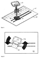
- Figure 1 shows an example of a preferred device (101) of the invention.
- a platform (103) is provided onto which a pair of parallel rails (105) are mounted.
- the rails can be provided within a space provided in the platform (see Figures 8 - 10 ).
- Base (107), onto which the user support their weight, is moveable mounted onto the platform (103) for movement along the rails (105) and for rotational movement about vertical axis defined by a vertical column (109) which extends or projects from the base (107).
- the base (107) is mounted on a further rotational support (108) which is adapted to allow the rotation of base (107) about said vertical axis.
- Square frame (113) is provided at the top of vertical column (109).
- An object rest is also visible in its position mounted onto the frame (115).
- the controller can be provided in this same position.
- Figure 2 shows the direction of rotation of the base (107) about the vertical axis perpendicular to the base (107). The direction of rotation is indicated by the arrows.
- FIG. 3 shows the device (101) removed from the platform (103).
- the rotational support (108) which is adapted to allow for rotation can be observed.
- Figure 4 shows the user (119) about to dismount the device (101) onto a bed (121). A wheelchair and bed are also shown in this drawing.
- Figure 5 shows the user about to dismount the device (101) onto the wheelchair.
- Figure 6 shows a close up of how the base (107) mounted on the rotation support (108) moves along the parallel rails (105).
- Grooves (106) are provided on both opposing sides of the rails (105).
- Tongues (125) provided on linear runners (127) which are in turn provided on the underside of rotation support (108) for securely engagement in the grooves (106) of the rails (105) by sitting into the grooves (107) thereby locking the base (107) to the rails (105) thereby forming the sliding arrangement, in such as way as to allow movement in one direction (along length of rails (105)).
- FIG 7 shows the underside of rotation support (108) and typical positioning of linear runners (127).
- the tongues (125) of the linear runners (127) are shown in broken lines in this drawing. Also shown in the attachment (110) of the vertical column (109) and inner vertical column (112) (not shown in this drawing) to the rotation base (108).
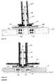
- Figure 8 shows a schematic drawing of one arrangement of the invention wherein the rails (105) are provided within the body of the platform (103).
- the runners (127) are located on the underside of rotation support (108) and are dimensioned to sit flush with the surface of the platform (103) in this particular embodiment.
- Inner vertical column (112) can be seen extending upright from the rotation support (108).
- the base (107) and vertical column (109) for supporting the user is rotatably mounted on top of the rotation support (108) and inner vertical column (112), so that the inner vertical column (112) sits within the vertical column (109).
- This arrangement is secured by a pair of rotation bearings (114), which rotatably couple the vertical column (109) and base (107) to the inner vertical column (112) and rotation support (108) for 360° rotation thereon.
- Figure 9 shows another example of the rotation arrangement, where a rotation ring (116) is provided between the base (107) and the rotation support (108). Circular groove (118) is provided in rotation support (108).
- the rotation ring (116) may be fixed attached to the rotation support (108) or to the underside of base (107) to facilitate rotation thereon. If necessary height adjustment blocks (120) can be provided underneath the rails (105) to adjust the rail height and height of rotation support (108) off the platform.
- Figure 10 shows a similar arrangement to that of Figure 9 , but the base (107) projects beyond that of the rotation support (108).
- the user In operation, on wishing to move position, the user simply moves the device (101) into an aligned position in front of them. The user may then rotate or swivel the device (101) around its base (107), so that the device (101) is orientated correctly in the mount position. This is the position in which the knee blocks (111) are in the correct orientation to act as supports for the user's legs.
- the device (101) When the device (101) is correctly aligned with the user, the user can reach towards to the handle (113) on the top of the device (101) and when a sufficient engagement is made, the user can pull themselves up towards the device (101) using their upper body strength. The user can grasp the handle (113) on the upper portion of the device (101) for support and to maintain their upright position.
- the user can then hold the handle (113) with one hand to support and steady themselves, while with the other hand they can to shift their feet and lower body weight onto the base (107) of the device (101).
- Feet, knees and thighs can be arranged to rest in position using the support blocks (111) provided on the vertical support of the device (101).
- the base (107), in its position mounted on top of rotation support (108) can be guided (mechanically or electrically or by hand if an assistant is available) along the pre-determined route set out by the rails (105) along the area to be traversed.
- the movement is facilitated by sliding the base (107) along the route provided by the captive rails (105), which in this embodiment, are fixed to a platform (103), which rests on the floor/ground of the user's bedroom other living space.
- the base (107) When the base (107) has reached the desired position, the base (107) may be rotated up to 360° about a vertical axis perpendicular to the plane of the rotation support (108), which stays stationary on the rails (105) in this instance, thereby allowing the user to correctly position themselves to safely dismount from the device (101), for example, onto a chair or a bed or bidet.
- Beds, wheelchairs or bidets etc. can be positioned along the line of the rails (105) so that the user or user's assistant can transfer themselves to the various apparatus using device (101) of the invention without requiring hoists or lifting equipment.
Landscapes
- Health & Medical Sciences (AREA)
- Nursing (AREA)
- Life Sciences & Earth Sciences (AREA)
- Animal Behavior & Ethology (AREA)
- General Health & Medical Sciences (AREA)
- Public Health (AREA)
- Veterinary Medicine (AREA)
- Invalid Beds And Related Equipment (AREA)
Priority Applications (1)
| Application Number | Priority Date | Filing Date | Title |
|---|---|---|---|
| EP12181221.8A EP2700391A1 (fr) | 2012-08-21 | 2012-08-21 | Dispositif de mobilité |
Applications Claiming Priority (1)
| Application Number | Priority Date | Filing Date | Title |
|---|---|---|---|
| EP12181221.8A EP2700391A1 (fr) | 2012-08-21 | 2012-08-21 | Dispositif de mobilité |
Publications (1)
| Publication Number | Publication Date |
|---|---|
| EP2700391A1 true EP2700391A1 (fr) | 2014-02-26 |
Family
ID=46851299
Family Applications (1)
| Application Number | Title | Priority Date | Filing Date |
|---|---|---|---|
| EP12181221.8A Withdrawn EP2700391A1 (fr) | 2012-08-21 | 2012-08-21 | Dispositif de mobilité |
Country Status (1)
| Country | Link |
|---|---|
| EP (1) | EP2700391A1 (fr) |
Cited By (1)
| Publication number | Priority date | Publication date | Assignee | Title |
|---|---|---|---|---|
| CN110121323A (zh) * | 2017-01-13 | 2019-08-13 | 株式会社富士 | 辅助装置 |
Citations (4)
| Publication number | Priority date | Publication date | Assignee | Title |
|---|---|---|---|---|
| DE2749146A1 (de) * | 1976-11-04 | 1978-05-18 | Abbink & Landhuis Metaal | Versehrten-hilfsgeraet |
| US20050224293A1 (en) * | 2004-04-12 | 2005-10-13 | Gordon Molnar | Stair lift device |
| US20100162488A1 (en) * | 2008-10-29 | 2010-07-01 | Oncolog Medical Qa Ab | Patient handling system |
| US20120023661A1 (en) * | 2010-07-30 | 2012-02-02 | Toyota Motor Engineering & Manufacturing North America, Inc. | Physical assistive robotic devices and systems |
-
2012
- 2012-08-21 EP EP12181221.8A patent/EP2700391A1/fr not_active Withdrawn
Patent Citations (4)
| Publication number | Priority date | Publication date | Assignee | Title |
|---|---|---|---|---|
| DE2749146A1 (de) * | 1976-11-04 | 1978-05-18 | Abbink & Landhuis Metaal | Versehrten-hilfsgeraet |
| US20050224293A1 (en) * | 2004-04-12 | 2005-10-13 | Gordon Molnar | Stair lift device |
| US20100162488A1 (en) * | 2008-10-29 | 2010-07-01 | Oncolog Medical Qa Ab | Patient handling system |
| US20120023661A1 (en) * | 2010-07-30 | 2012-02-02 | Toyota Motor Engineering & Manufacturing North America, Inc. | Physical assistive robotic devices and systems |
Cited By (5)
| Publication number | Priority date | Publication date | Assignee | Title |
|---|---|---|---|---|
| CN110121323A (zh) * | 2017-01-13 | 2019-08-13 | 株式会社富士 | 辅助装置 |
| JPWO2018131131A1 (ja) * | 2017-01-13 | 2019-11-07 | 株式会社Fuji | 介助装置 |
| EP3569211A4 (fr) * | 2017-01-13 | 2019-12-18 | Fuji Corporation | Dispositif d'assistance |
| AU2017392578B2 (en) * | 2017-01-13 | 2020-11-26 | Fuji Corporation | Assistance device |
| CN110121323B (zh) * | 2017-01-13 | 2022-04-26 | 株式会社富士 | 辅助装置 |
Similar Documents
| Publication | Publication Date | Title |
|---|---|---|
| US9161871B2 (en) | Multiple function patient handling devices and methods | |
| US10987266B2 (en) | Rotational/translational transfer lift | |
| US8522907B1 (en) | Personal mobility device | |
| JP5911559B2 (ja) | 身体障害者のための移動装置 | |
| US8336133B2 (en) | Multi-functional patient transfer device | |
| EP1912611B1 (fr) | Systeme de transfert de patient | |
| US4999862A (en) | Wheelchair mounted invalid lift | |
| KR102209833B1 (ko) | 신체적 약자를 위한 이동 이승을 위한 보조 로봇 | |
| US6880186B2 (en) | Arrangement in a bed for a disabled person, and a bed provided with the said arrangement | |
| US20150272797A1 (en) | Patient transfer device | |
| US10682275B2 (en) | Personal mobility device | |
| EP1156768B1 (fr) | Dispositif de levage et de transport pour personnes handicapees | |
| US20240398644A1 (en) | Caring machine, overhanging machine and host module comprised therein | |
| KR101462378B1 (ko) | 리프트가 구비된 휠체어 | |
| RU2771537C1 (ru) | Вспомогательное средство для стабилизации, мобилизации и фиксации пациента | |
| US20160058635A1 (en) | Mobility device | |
| US20230181410A1 (en) | Lift transfer apparatus | |
| JP5313385B2 (ja) | 要介護者移動用装置および歩行補助用装置としての使用に適した介護補助装置 | |
| WO2011028761A2 (fr) | Dispositif de levage et de support pour un patient | |
| JP2007202880A (ja) | 歩行器 | |
| WO2011151639A1 (fr) | Appareil de levage de patient | |
| US20160256341A1 (en) | Positioning Mat for Bedridden Patients | |
| JP2506558Y2 (ja) | ベッド等における立上り補助具 | |
| JP5894328B1 (ja) | 介護補助装置 | |
| JP6112368B2 (ja) | 介護用移送リフト |
Legal Events
| Date | Code | Title | Description |
|---|---|---|---|
| PUAI | Public reference made under article 153(3) epc to a published international application that has entered the european phase |
Free format text: ORIGINAL CODE: 0009012 |
|
| AK | Designated contracting states |
Kind code of ref document: A1 Designated state(s): AL AT BE BG CH CY CZ DE DK EE ES FI FR GB GR HR HU IE IS IT LI LT LU LV MC MK MT NL NO PL PT RO RS SE SI SK SM TR |
|
| AX | Request for extension of the european patent |
Extension state: BA ME |
|
| 17P | Request for examination filed |
Effective date: 20140822 |
|
| RBV | Designated contracting states (corrected) |
Designated state(s): AL AT BE BG CH CY CZ DE DK EE ES FI FR GB GR HR HU IE IS IT LI LT LU LV MC MK MT NL NO PL PT RO RS SE SI SK SM TR |
|
| 17Q | First examination report despatched |
Effective date: 20151001 |
|
| STAA | Information on the status of an ep patent application or granted ep patent |
Free format text: STATUS: THE APPLICATION IS DEEMED TO BE WITHDRAWN |
|
| 18D | Application deemed to be withdrawn |
Effective date: 20170301 |