EP2700433A2 - Systeme und Verfahren für (wieder-) aufblasbaren Lawinenschutz - Google Patents
Systeme und Verfahren für (wieder-) aufblasbaren Lawinenschutz Download PDFInfo
- Publication number
- EP2700433A2 EP2700433A2 EP13181476.6A EP13181476A EP2700433A2 EP 2700433 A2 EP2700433 A2 EP 2700433A2 EP 13181476 A EP13181476 A EP 13181476A EP 2700433 A2 EP2700433 A2 EP 2700433A2
- Authority
- EP
- European Patent Office
- Prior art keywords
- period
- inflatable chamber
- inflation system
- inflation
- deactivating
- Prior art date
- Legal status (The legal status is an assumption and is not a legal conclusion. Google has not performed a legal analysis and makes no representation as to the accuracy of the status listed.)
- Granted
Links
Images


Classifications
-
- A—HUMAN NECESSITIES
- A62—LIFE-SAVING; FIRE-FIGHTING
- A62B—DEVICES, APPARATUS OR METHODS FOR LIFE-SAVING
- A62B33/00—Devices for allowing seemingly-dead persons to escape or draw attention; Breathing apparatus for accidentally buried persons
Definitions
- the invention generally relates to inflatable avalanche safety systems and methods of operation.
- the present invention relates to systems and methods for efficient inflation of an avalanche safety chamber.
- One type of emergency life-preserving equipment is an inflatable safety system configured to inflate a chamber in response to an emergency event such as an impact or a potential impact.
- an emergency event such as an impact or a potential impact.
- automobile driver inflatable safety systems are designed to automatically inflate a chamber over the steering wheel in response to an impact between the automobile and another object so as to protect the driver from forceful impact with interior structures of the automobile.
- avalanche inflatable safety systems are designed to manually inflate a chamber adjacent to the user in response to the user's triggering of an inflation mechanism.
- Inflatable safety systems generally include an inflatable chamber, an activation system, and an inflation system.
- the inflatable chamber is designed to expand from a compressed state to an inflated state so as to cushion the user or dampen potential impact.
- the inflatable chamber may also be used to encourage the user to elevate over a particular surface.
- the elevation of the inflatable chamber is achieved by the concept of inverse segregation, in which larger volume particles are sorted towards the top of a suspension of various sized particles in motion.
- the activation system enables manual or automatic activation of the inflation system.
- the inflation system transmits a fluid such as a gas into the inflatable chamber, thus increasing the internal pressure within the inflatable chamber and thereby transitioning the inflatable chamber from the compressed state to the inflated state.
- conventional inflatable avalanche safety systems fail to provide an efficient safety system.
- conventional systems are limited to single use in-field operation.
- the portable compressed gas canisters used in the conventional systems are generally configured to only contain a sufficient volume for a single deployment and therefore must be completely replaced to rearm the system. Therefore, if a user inadvertently deploys the system, it cannot be rearmed without replacing the canister.
- conventional systems include one or more combustible or pressurized components that are not permitted on airplanes and helicopters, thus limiting the systems' use in travel situations.
- conventional avalanche inflatable systems require a complex rearming procedure that includes replacing at least one component to enable repeated use. This may compromise user safety or system operation if performed incorrectly.
- the inflatable chamber is generally inflated for a predetermined period of time corresponding to the inflation mechanism.
- the inflation period is intended to be performed by the user prior to avalanche contact. Therefore, during avalanche contact and transport, the inflatable chamber may contact various debris contained within the avalanche medium. For example, sharp objects such as ice and rock may be transported within the avalanche at differing speeds with respect to the user. Contact between the sharp objects and the inflatable chamber may thereby result in a puncture or tear and subsequent deflation. Deflation of the inflatable chamber will then compromise the safety provided by the inflatable avalanche system and expose the user to increased danger.
- the present invention generally relates to inflatable avalanche safety systems and methods of operation.
- One embodiment of the present invention relates to an avalanche safety system including an inflatable chamber, activation system, inflation system, and a harness.
- the inflatable chamber is a three-dimensionally, partially enclosed region having an inflated state and a compressed state.
- the inflated state may form a particular three dimensional shape configured to protect the user from impact and/or provide inverse segregation during an avalanche.
- the activation system is configured to receive a user-triggered action to activate the system.
- the activation system also includes a reinflation algorithm configured to automatically reactivate the inflation system after a period of time to maintain the inflated state of the inflatable chamber.
- the inflation system may include an air intake, battery, fan, and internal airway channel.
- the inflation system is configured to transmit ambient air into the inflatable chamber.
- the harness may be a backpack that enables a user to transport the system while engaging in activities that may be exposed to avalanche risk.
- the harness may include hip straps, shoulder straps, internal compartments, etc.
- Embodiments of the present invention represent a significant advance in the field of avalanche safety systems.
- the limitations of conventional avalanche safety systems are overcome by using ambient air rather than a canister of compressed gas.
- ambient air avoids the explosive dangers associated with compressed gas canisters, rendering the device legal for air transportation.
- ambient air is unlimited and therefore enables multiple inflations and/or inadvertent deployments.
- the procedure to rearm the system is simplified to enable intuitive user operation.
- Embodiments of the present invention overcome or minimize the susceptibility of the inflatable chamber to deflate as a result of a rip or tear.
- Embodiments of the present invention include an activation system with a reinflation algorithm.
- the activation system may include a continuous use of the inflation system at a prescribed power level or any sequential deactivating and reactivating of the inflation system to maintain inflation of the inflatable chamber.
- the activation system may also include a pressure sensor within the airbag system which will allow the system to automatically identify a leak and provide airflow as required to maintain proper inflation.
- Figure 1 illustrates a profile view of an avalanche safety system in accordance with embodiments of the present invention
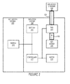
- Figure 2 illustrates a schematic of the avalanche safety system illustrated in Figure 1 ;
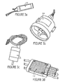
- FIG. 3a-d illustrates perspective views of inflation system components
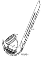
- Figure 4 illustrates a perspective view of the air intake frame, internal airway channel, and fan
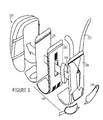
- Figure 5 illustrates an exploded view of the air intake with respect to the remainder of the avalanche safety system
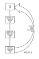
- Figure 6 illustrates a flow chart of a method in accordance with another embodiment of the present invention.
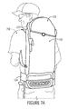
- Figures 7A-7C illustrate an operational sequence of the system in Figure 1 and the method of Figure 6 ;
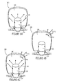
- FIGS 8A-C illustrate an operational inflation and reinflation sequence in accordance with embodiments of the present invention.
- the present invention generally relates to inflatable avalanche safety systems and methods of operation.
- One embodiment of the present invention relates to an avalanche safety system including an inflatable chamber, activation system, inflation system, and a harness.
- the inflatable chamber is a three-dimensionally, partially enclosed region having an inflated state and a compressed state.
- the inflated state may form a particular three dimensional shape configured to protect the user from impact and/or provide flotation during an avalanche.
- the activation system is configured to receive a user-triggered action to activate the system.
- the activation system also includes a reinflation algorithm configured to automatically reactivate the inflation system after a period of time to maintain the inflated state of the inflatable chamber.
- the inflation system may include an air intake, battery, fan, and internal airway channel.
- the inflation system is configured to transmit ambient air into the inflatable chamber.
- the harness may be a backpack that enables a user to transport the system while engaging in activities where they may be exposed to avalanche risk.
- the harness may include hip straps, shoulder straps, internal compartments, etc. Also, while embodiments are described in reference to an avalanche safety system, it will be appreciated that the teachings of the present invention are applicable to other areas including but not limited to non-avalanche impact safety systems.
- FIG. 1 illustrates a profile view of an avalanche safety system, designated generally at 100.
- the illustrated system 100 includes an inflatable chamber 140, an inflation system 160, an activation system (not shown), and a harness 120.
- the inflatable chamber 140 is a three dimensional, inflatable, partially enclosed structure.
- the inflatable chamber 140 includes an inlet (not shown) and a particular inflated shape.
- the inflatable chamber 140 is illustrated in the compressed state in Figure 1 .
- the compressed state includes substantially expelling air from within the inflatable chamber and compressing the external surface of the inflatable chamber upon itself.
- Figure 7C illustrates the inflated state of the inflatable chamber.
- the inflated state of the inflatable chamber includes expansion of the external surface away from its compressed state, substantially analogous to the inflation of a balloon.
- the inflatable chamber may include a particular three dimensional inflated shape such that upon inflation, the external surfaces are forced to form the shape.
- the inflatable chamber may be configured to include multiple chambers, multiple regions, etc.
- Figure 7C illustrates one embodiment of an inflated shape including a substantially pillow-shaped form with two horn members. It will be appreciated that various other shapes may be practiced in accordance with embodiments of the present invention.
- the inflatable chamber 140 may be configured to wrap around the head and/or torso of the user.
- the inflation system 160 is configured to transition the inflatable chamber 140 from the compressed state to the inflated state.
- the inflation system 160 may further include an air intake 180, a fan 164, a battery 166, an internal airway channel 168, a motor 170, and a controller 172.
- the air intake 180 provides an inlet for receiving ambient air.
- the illustrated air intake 180 includes an elongated vent structure through which ambient air may flow.
- the air intake 180 is coupled to the internal airway channel 168 such that ambient air may be transmitted through the air intake 180 to the internal airway channel with minimal loss.
- the components and operation of the air intake will be described in more detail with reference to Figure 5 below.
- the fan 164, battery 166, motor 170, and controller 172 are the electrical components of the inflation system.
- the electrical components of the inflation system 160 are electrically coupled to the activation system as illustrated in Figure 2 .
- the fan 164 is a rotational member configured to generate a vacuum force in a particular orientation upon rotation.
- the fan is oriented in the system 100 to generate the vacuum force such that ambient air is pulled into the inflatable chamber 140. It will be appreciated that fans in a variety of sizes may be used in accordance with embodiments of the present invention.
- the battery 166 may be any form of electrical storage device.
- the motor 170 converts electrical energy into mechanical rotation.
- the controller 172 may be any form of speed controller to facilitate particular inflation patterns such as a logarithmic increase in fan speed.
- the fan 164, battery 166, motor 170, and controller 172 are selected to correspond with one another to facilitate optimal inflation characteristics. For example, the size of fan 164 dictates the necessary speed and time required to inflate the inflatable chamber 140. The speed and time parameters thereby influence optimal selection of the remaining electrical components.
- the activation system 190 is configured to activate the inflation system 160 to expand the inflatable chamber 140 to the inflated state.
- the activation system 190 is a user input device configured to a user-triggered action intended to activate the system 100.
- the particular user-triggered action depends on the specific type of activation system components.
- the activation system 190 may include some form of physical switch configured to receive a physical switching motion from the user in order to activate the system 100.
- the switch may be any type of switching mechanism including but not limited to a rip cord, push button, toggle, etc.
- the activation system 190 is electrically coupled to the inflation system 160 so as to engage the inflation system upon receipt of the user-triggered action.
- the activation system 190 may include other sensors designed to activate the system without a user-triggered action.
- the activation may include a deactivation switch.
- the deactivation switch may be used to deactivate the system in the event of an inadvertent activation.
- the harness 120 couples the system 100 to the user 200 as illustrated in Figures 7A-7C .
- the illustrated harness 120 in Figures 1-7 is a backpack-style unit including a hip strap 124 and a shoulder strap 122.
- the backpack configuration provides an internal chamber separate from the inflatable chamber 140 within which the user may store items.
- the internal chamber is disposed between the user and the inflatable chamber 140 such that the inflatable chamber is distally disposed with respect to the remainder of the harness/backpack 120 and the user. Therefore, upon activation, the inflatable chamber will be able to inflate without obstruction.
- the inflation system 160 is distal to the inflatable chamber 140 in the illustrated embodiment.
- the inflation system 160 may be disposed within a region configured to break away or articulate upon the inflation of the inflatable chamber 140, as illustrated in Figures 7A-C .
- the backpack or harness may further include various other straps and compartments in accordance with embodiments of the present invention.
- the harness may be any form of simple strap apparatus configured to couple the system to the user.
- the activation system 190 includes a switch 192. As discussed above, the activation system 190 is configured to receive a user-triggered action intended to activate the avalanche safety system 100 and inflate the inflatable chamber 140.
- the switch 192 is electrically coupled to the inflation system 160 between the battery 166 and the controller 172. As described above, the battery 166 stores electrical energy for use in inflating the inflatable chamber 140.
- the controller 172 is electrically coupled between the battery 166 and the motor 170. The controller 172 may provide a particular electrical inflation profile, including the modulation of current with respect to time.
- the motor 170 is electrically coupled to the controller 172 and fan 164 such that the modulated current from the controller 172 may be converted into mechanical rotation of the fan 164.
- the fan 164 is mechanically disposed between the air intake 180 and the inflatable chamber 140.
- an internal airway channel 168 connects the air intake 180, fan 164, and inflatable chamber 140 so as to minimize air loss.
- the fan 164 upon activation, the fan 164 generates a rotational force that creates a vacuum aligned with the illustrated arrows. The vacuum pulls external ambient air through the air intake 180, through the fan 164, and into the inflatable chamber 140.
- the battery 166 may be any type of electrical storage device including but not limited to a direct current battery of the type illustrated.
- the fan 164 may be a circular fan that facilitates engagement with the internal airway channel 168.
- the motor 170 may be any type of motor 170 configured to correspond to the battery 166 and controller 172 parameters. Likewise, the controller 172 may be configured according to the inflation objectives for the inflatable chamber 140.
- FIG. 4 illustrates a perspective view of the air intake frame 182, internal airway channel 168, and fan 164.
- the air intake frame 182 is part of the air intake 180.
- Various other air intakes may also be incorporated, including but not limited to the sides, bottom and front of the system 100. Increasing the number of air intake regions increases reliability of the air intake system during operation.
- the air intake frame 182 is a partially rigid member with a lateral vent structure as illustrated.
- the lateral vent structure includes a channel to the internal airway channel 168. Therefore, air/gas transmitted through the lateral vents may be routed to the internal airway channel 168.
- the air intake frame 182 includes rigid internal structure members in order to maintain the channel.
- the illustrated internal airway channel 168 is a cylindrical member coupled between the air intake frame 182 and the fan 164.
- the internal airway channel 168 substantially encloses the coupling so as to minimize air leakage between the air intake frame 182 and the fan 164.
- the fan 164 is coupled to the internal airway channel 164.
- the inflatable chamber 140 (not shown in Figure 4 ) is coupled to the fan 164 either directly or via another internal airway channel member (not shown).
- FIG. 5 illustrates an exploded view of the air intake 180 with respect to the remainder of the avalanche safety system.
- the air intake 180 includes the air intake frame 182 (illustrated in Figure 4 ), a battery compartment 186, and a cover 184.
- the battery compartment 186 is configured to be disposed within the air intake frame 182.
- the positioning of the battery compartment 186 and the battery (not shown) with respect to the user is important because of the relative weight of most batteries. Therefore, positioning the battery 164 in a central region enables the shoulder 122 and hip straps 124 of the backpack (harness 120) to efficiently support the battery during operation.
- the cover 184 includes padded regions and mesh regions.
- the padded regions facilitate user comfort and are disposed between the user and the air intake frame 182.
- the mesh regions are oriented to align with the lateral venting structure of the air intake frame 182. Therefore, ambient air may transmit through the mesh regions and into the air intake frame 182 as discussed above.
- the mesh regions prevent debris from obstructing the vent structure of the air intake frame 182.
- Figure 5 further illustrates a frame 126 member of the backpack or harness 120.
- the frame 126 may include a rigid support region for further supporting the system with respect to the user.
- the exploded view illustrates the positioning of the air intake 180 and the frame 126 with respect to the remainder of the system 100.
- the hip/waist straps 124 and the shoulder straps 122 are also illustrated in the exploded view for positional reference.
- the method for inflating an inflatable chamber within an avalanche safety system comprises a plurality of acts.
- the illustrated method may be performed using the avalanche safety system 100 described above or in correlation with an alternative avalanche safety system.
- the method includes receiving a user-triggered action intended to activate the avalanche safety system, 210.
- the user-triggered action may include a physical operation or gesture such as pulling a ripcord or depressing a button.
- the act of receiving a user-triggered action may include receiving a non-physical operation.
- the method transmits ambient air to the inflatable chamber, 220.
- the act of transmitting ambient air to the inflatable chamber may include generating a vacuum that transmits ambient air through an internal airway channel to the inflatable chamber.
- the act of generating a vacuum may include using a fan and/or other electrical components.
- the inflatable chamber is inflated, act 230.
- the act of inflating the inflatable chamber may include inflation entirely with ambient air.
- the act of inflating the inflatable chamber may also include forming a particular three dimensional shape and internal pressure of the inflatable chamber.
- the inflation of the inflatable chamber thereby protects the user from an avalanche, act 240.
- the act of protecting the user from an avalanche may include cushioning the user from impact during the avalanche, elevating the user above the avalanche debris, and/or providing a breathing receptacle of ambient air.
- Figure 7A illustrates a user 200 with an avalanche safety system 100 in accordance with embodiments of the present invention.
- the user 200 is wearing the system 100 via a backpack harness structure including a set of hip/waist straps 124 and shoulder straps 122.
- the system includes an activation system 190 (not shown), inflation system 160 and inflatable chamber 140 as described above.
- Figure 7A illustrates the inflatable chamber 140 in the compressed state so as to be contained within a region of the backpack.
- the system illustrated in Figure 7A has not been activated and therefore the user has not performed any type of user-triggered action upon the activation system 190.
- the user Prior to Figure 7B , the user performs a particular user-triggered action such as pulling a ripcord or pressing a button to activate the system 100.
- the activation system includes an electrical coupling that activates the components of the inflation system 160.
- activation of the activation system 190 may include switching a switch so as to remove electrical resistance between a battery and other electrical components.
- the inflation system 160 transmits ambient air to the inflatable chamber 140.
- Figure 7B represents the transition from the compressed state to the inflated state of the inflatable chamber 140.
- the inflatable chamber 140 is partially filled with ambient air directed through an air intake 180, internal airway channel 168, and fan 164.
- a controller 172 may be used to inflate the inflatable chamber 140 according to a particular inflation profile.
- the inflation system 160 automatically translates in response to the inflation of the inflatable chamber 140.
- the inflation system 160 is disposed within a region that is translating to the right as the inflatable chamber 140 is expanding.
- the inflation system 160 may be housed within a region with a releasable coupling (such as VELCRO) to the remainder of the system, thereby enabling automatic displacement in response to inflation.
- Figure 7C illustrates complete transition to the inflated state of the inflatable chamber 140.
- the inflatable chamber 140 thereby forms a particular three dimensional shape and has a particular pressure.
- the particular three dimensional shape and pressure of the inflatable chamber are specifically selected to protect the user 200 from impact and provide for inverse segregation during an avalanche.
- the pressure within the inflatable chamber may be maintained for a particular time using a one way valve that seals the inlet from transmitting air out from the inflatable chamber 140.
- the controller 172 may be configured to shut off and/or restart the fan 164 after a certain amount of time corresponding to complete inflation of the inflatable chamber 140.
- the illustrated avalanche safety system 300 includes an inflatable chamber 340 and a harness 324, 330.
- the inflatable chamber 340 is coupled to the harness 324, 330 and is configured to include a compressed state (see Fig 7A ) and an inflated state.
- the operation and specific configuration of the inflatable chamber 340 is described above. It will be appreciated that various shapes and materials may be used to manufacture the inflatable chamber 340 in accordance with embodiments of the present invention.
- the harness 324, 330 includes a waist strap 324 and a backpack 330 configured to support, orient, and position the inflatable chamber 340 adjacent to a user in both the compressed and inflated states.
- the illustrated harness 324, 330 is configured to support the inflatable chamber on the back region of a user as illustrated in Figures 7A-C .
- the system 300 includes an activation system (not shown) which receives the user-triggered action and automatically activates an inflation system (not shown).
- the inflation system is configured to actively transmit ambient air within the inflatable chamber using a fan (not shown), thereby transitioning the inflatable chamber from the compressed state to the inflated state.
- the term "active” is used to describe the transmission of ambient air into the inflated chamber substantially via the turbulent force generated by the fan.
- “passive" transmission of ambient air is limited to air transmission generated naturally and/or assisted by the application of manual force from the user.
- the activation system of the system 300 includes a reinflation algorithm.
- the reinflation algorithm of the activation system includes automatically deactivating the inflation system for a second period of time and reactivating the inflation system for a third period of time.
- the reinflation algoritm of the activation system is configured to maintain inflation of the inflatable chamber 340 in the event of a rip or tear 360, which causes an external transmission 370 of the ambient air contained within the inflatable chamber 340 ( Figures 8B and C ).
- a user initially activates the system 300 via the execution of a user-triggered action.
- the initial activation of the inflation system causes the active transmission of ambient air 350 into the inflatable chamber for a first period of time, illustrated in Figure 8A .
- the duration of the first period corresponds to the battery power, fan diameter, and internal area of the inflatable chamber 340.
- the first period of time is selected so as to inflate the inflatable chamber to a particular pressure based on the rate at which the fan transmits ambient air.
- the rate at which the fan transmits ambient air through the system 300 is dependent on multiple variables, including the battery, the fan, the size of the air inlets, the size of the internal airway channel, the size of the valve disposed between the fan and the inflatable chamber, etc.
- the particular pressure of the inflatable chamber corresponds to a set of predetermined safety parameters of the system, including buoyancy, flotation, etc. Therefore, if a smaller battery and fan are used, a longer period of time will be necessary to properly inflate the inflatable chamber to the particular pressure.
- the inflation system is deactivated for a second period of time ( Figure 8B ) according to the reinflation algorithm.
- the activation system is subsequently reactivated according the reinflation algorithm for a third period of time ( Figure 8C ) according to the reinflation algorithm.
- the deactivation ( Figure 8B ) and reactivation ( Figure 8C ) may be repeated/cycled a particular number of times to maintain proper inflation of the inflatable chamber 340.
- the particular duration of the second and third period and the number of cycles may be predetermined and/or may correspond to one or more parameters, including inflatable chamber pressure, rip detection, user triggering action, etc.
- the reinflation algorithm may dynamically adjust the duration of the first and second periods and/or the number of cycles based on the inflatable chamber pressure.
- One reinflation algorithm embodiment may include a predetermined second period of two seconds, a third period of three seconds, and a five cycle repeat. Overinflation of the inflatable chamber 340 is unlikely with ambient air and therefore it is not necessary to restrict reinflation to the positive detection of a rip/tear 360.
- the reinflation algorithm may therefore be predetermined and independent of any detected parameters.
- the reinflation algorithm may be selected to correspond to the necessary frequency so as to maintain a necessary safety pressure of the inflatable chamber 340 in the event of the most likely sized rip/tear 360.
- the transmission of ambient air 350 into the inflatable chamber 340 may therefore overcome the external transmission 370 of ambient air from the rip/tear 360.
- the material composition or stitch pattern of the inflatable chamber 340 may also be configured to contain or restrict an external rip/tear 360 to a particular maximum size.
Landscapes
- Health & Medical Sciences (AREA)
- Pulmonology (AREA)
- General Health & Medical Sciences (AREA)
- Business, Economics & Management (AREA)
- Emergency Management (AREA)
- Emergency Lowering Means (AREA)
- Devices Affording Protection Of Roads Or Walls For Sound Insulation (AREA)
- Professional, Industrial, Or Sporting Protective Garments (AREA)
Applications Claiming Priority (1)
| Application Number | Priority Date | Filing Date | Title |
|---|---|---|---|
| US13/594,224 US8851948B2 (en) | 2011-12-13 | 2012-08-24 | Systems and methods for inflatable avalanche protection with reinflation |
Publications (3)
| Publication Number | Publication Date |
|---|---|
| EP2700433A2 true EP2700433A2 (de) | 2014-02-26 |
| EP2700433A3 EP2700433A3 (de) | 2014-12-17 |
| EP2700433B1 EP2700433B1 (de) | 2020-03-11 |
Family
ID=49033894
Family Applications (1)
| Application Number | Title | Priority Date | Filing Date |
|---|---|---|---|
| EP13181476.6A Active EP2700433B1 (de) | 2012-08-24 | 2013-08-23 | Systeme und Verfahren für aufblasbaren Lawinenschutz mit Wiederaufblasmechanismus |
Country Status (1)
| Country | Link |
|---|---|
| EP (1) | EP2700433B1 (de) |
Cited By (4)
| Publication number | Priority date | Publication date | Assignee | Title |
|---|---|---|---|---|
| EP3146999A1 (de) * | 2015-09-22 | 2017-03-29 | Black Diamond Equipment AG | Systeme und verfahren für modularen aufblasbaren lawinenschutz |
| EP3202462A1 (de) | 2016-02-08 | 2017-08-09 | RAS Technology Sàrl | Vorrichtung zum aufblasen eines aufblasbaren beutels, lawinensicherheitssystem und rucksack mit solch einer vorrichtung und verwendung |
| DE102022123470A1 (de) | 2022-08-29 | 2024-02-29 | ADVENATE GmbH | Rettungssystem umfassend einen aufblasbaren Auftriebsairbag |
| WO2024047029A1 (de) | 2022-08-29 | 2024-03-07 | ADVENATE GmbH | Rettungssystem umfassend einen aufblasbaren auftriebsairbag |
Family Cites Families (8)
| Publication number | Priority date | Publication date | Assignee | Title |
|---|---|---|---|---|
| US4920674A (en) * | 1988-11-14 | 1990-05-01 | Shaeffer Henry W | Inflatable communication device |
| CA2237627C (en) * | 1995-05-09 | 2007-01-23 | Peter Aschauer | Lifesaving device for people in avalanches |
| DE19703656A1 (de) * | 1997-01-31 | 1998-08-06 | Peter Aschauer | Lawinenrettungssystem |
| WO2000032274A1 (en) * | 1998-12-02 | 2000-06-08 | Avagear, Inc. | Avalanche life-preserving jacket with airbag |
| US7270077B2 (en) * | 2005-09-12 | 2007-09-18 | Ralph Frank Beck | Avalanche survival kit |
| DE502006005545D1 (de) * | 2006-12-22 | 2010-01-14 | Peter Aschauer | Lawinenrettungsgerät |
| US7878141B2 (en) * | 2009-01-21 | 2011-02-01 | Backcountry Access, Inc. | Airbag system for use in an avalanche |
| US8876568B2 (en) * | 2010-09-14 | 2014-11-04 | Arc'teryx Equipment Inc. | Airbag rescue system |
-
2013
- 2013-08-23 EP EP13181476.6A patent/EP2700433B1/de active Active
Cited By (5)
| Publication number | Priority date | Publication date | Assignee | Title |
|---|---|---|---|---|
| EP3146999A1 (de) * | 2015-09-22 | 2017-03-29 | Black Diamond Equipment AG | Systeme und verfahren für modularen aufblasbaren lawinenschutz |
| EP3202462A1 (de) | 2016-02-08 | 2017-08-09 | RAS Technology Sàrl | Vorrichtung zum aufblasen eines aufblasbaren beutels, lawinensicherheitssystem und rucksack mit solch einer vorrichtung und verwendung |
| WO2017137244A1 (en) * | 2016-02-08 | 2017-08-17 | Ras Technology Sàrl | Device for inflating an inflatable bag, avalanche safety system and a backpack with such a device and use |
| DE102022123470A1 (de) | 2022-08-29 | 2024-02-29 | ADVENATE GmbH | Rettungssystem umfassend einen aufblasbaren Auftriebsairbag |
| WO2024047029A1 (de) | 2022-08-29 | 2024-03-07 | ADVENATE GmbH | Rettungssystem umfassend einen aufblasbaren auftriebsairbag |
Also Published As
| Publication number | Publication date |
|---|---|
| EP2700433A3 (de) | 2014-12-17 |
| EP2700433B1 (de) | 2020-03-11 |
Similar Documents
| Publication | Publication Date | Title |
|---|---|---|
| US8851948B2 (en) | Systems and methods for inflatable avalanche protection with reinflation | |
| US9289633B2 (en) | Systems and methods for inflatable avalanche protection | |
| US9004116B2 (en) | Systems and methods for inflatable avalanche protection | |
| US8851949B2 (en) | Systems and methods for inflatable avalanche protection with active deflation | |
| US9492711B2 (en) | Systems and methods for modular inflatable avalanche protection | |
| US8777684B2 (en) | Systems and methods for inflatable avalanche protection with system diagnostic | |
| CA2811303C (en) | Airbag rescue system | |
| US8038097B1 (en) | Vehicle recovery package | |
| US8118255B1 (en) | Vehicle energy absorption | |
| EP2700433B1 (de) | Systeme und Verfahren für aufblasbaren Lawinenschutz mit Wiederaufblasmechanismus | |
| US9675505B2 (en) | System and method for preventing fall-related injuries | |
| US20100299837A1 (en) | Vacuum packed inflatable stretcher with frangible overwrap and method of deploying same | |
| US7686247B1 (en) | Vehicle recovery | |
| US12564742B2 (en) | Inflatable bag, avalanche backpack and method of deflating an inflatable bag | |
| EP2604318B1 (de) | Systeme und Verfahren für aufblasbaren Lawinenschutz mit aktiver Abblasung | |
| EP3146999A1 (de) | Systeme und verfahren für modularen aufblasbaren lawinenschutz | |
| JP2007175266A (ja) | 患者搬送装置 | |
| CN204033547U (zh) | 髋关节安全防护气囊装置 | |
| GB2581781A (en) | Infant sleep aid system | |
| CA2893860C (en) | Recovery device | |
| CN120052629A (zh) | 颈部防护装置及其控制方法、计算机可读存储介质 | |
| AU2018226376A1 (en) | Water Safety Device |
Legal Events
| Date | Code | Title | Description |
|---|---|---|---|
| PUAI | Public reference made under article 153(3) epc to a published international application that has entered the european phase |
Free format text: ORIGINAL CODE: 0009012 |
|
| AK | Designated contracting states |
Kind code of ref document: A2 Designated state(s): AL AT BE BG CH CY CZ DE DK EE ES FI FR GB GR HR HU IE IS IT LI LT LU LV MC MK MT NL NO PL PT RO RS SE SI SK SM TR |
|
| AX | Request for extension of the european patent |
Extension state: BA ME |
|
| PUAL | Search report despatched |
Free format text: ORIGINAL CODE: 0009013 |
|
| AK | Designated contracting states |
Kind code of ref document: A3 Designated state(s): AL AT BE BG CH CY CZ DE DK EE ES FI FR GB GR HR HU IE IS IT LI LT LU LV MC MK MT NL NO PL PT RO RS SE SI SK SM TR |
|
| AX | Request for extension of the european patent |
Extension state: BA ME |
|
| RIC1 | Information provided on ipc code assigned before grant |
Ipc: A62B 33/00 20060101AFI20141110BHEP |
|
| 17P | Request for examination filed |
Effective date: 20150617 |
|
| RBV | Designated contracting states (corrected) |
Designated state(s): AL AT BE BG CH CY CZ DE DK EE ES FI FR GB GR HR HU IE IS IT LI LT LU LV MC MK MT NL NO PL PT RO RS SE SI SK SM TR |
|
| STAA | Information on the status of an ep patent application or granted ep patent |
Free format text: STATUS: EXAMINATION IS IN PROGRESS |
|
| 17Q | First examination report despatched |
Effective date: 20170216 |
|
| RAP1 | Party data changed (applicant data changed or rights of an application transferred) |
Owner name: BLACK DIAMOND EQUIPMENT EUROPE GMBH |
|
| GRAP | Despatch of communication of intention to grant a patent |
Free format text: ORIGINAL CODE: EPIDOSNIGR1 |
|
| STAA | Information on the status of an ep patent application or granted ep patent |
Free format text: STATUS: GRANT OF PATENT IS INTENDED |
|
| INTG | Intention to grant announced |
Effective date: 20191021 |
|
| RIN1 | Information on inventor provided before grant (corrected) |
Inventor name: WALKER, JOSEPH BENJAMIN Inventor name: ROBERT JOHN, HORACEK Inventor name: GOMPERT, PETER THOMAS Inventor name: KUDER, NATHAN Inventor name: DAVID, KULHMANN BLACKWELL Inventor name: GRUTTA, JAMES THOMAS Inventor name: NOFFSINGER, DERRICK |
|
| GRAS | Grant fee paid |
Free format text: ORIGINAL CODE: EPIDOSNIGR3 |
|
| GRAA | (expected) grant |
Free format text: ORIGINAL CODE: 0009210 |
|
| STAA | Information on the status of an ep patent application or granted ep patent |
Free format text: STATUS: THE PATENT HAS BEEN GRANTED |
|
| AK | Designated contracting states |
Kind code of ref document: B1 Designated state(s): AL AT BE BG CH CY CZ DE DK EE ES FI FR GB GR HR HU IE IS IT LI LT LU LV MC MK MT NL NO PL PT RO RS SE SI SK SM TR |
|
| REG | Reference to a national code |
Ref country code: GB Ref legal event code: FG4D |
|
| REG | Reference to a national code |
Ref country code: CH Ref legal event code: EP |
|
| REG | Reference to a national code |
Ref country code: AT Ref legal event code: REF Ref document number: 1242412 Country of ref document: AT Kind code of ref document: T Effective date: 20200315 |
|
| REG | Reference to a national code |
Ref country code: IE Ref legal event code: FG4D |
|
| REG | Reference to a national code |
Ref country code: DE Ref legal event code: R096 Ref document number: 602013066617 Country of ref document: DE |
|
| REG | Reference to a national code |
Ref country code: CH Ref legal event code: NV Representative=s name: BRAUNPAT BRAUN EDER AG, CH |
|
| PG25 | Lapsed in a contracting state [announced via postgrant information from national office to epo] |
Ref country code: NO Free format text: LAPSE BECAUSE OF FAILURE TO SUBMIT A TRANSLATION OF THE DESCRIPTION OR TO PAY THE FEE WITHIN THE PRESCRIBED TIME-LIMIT Effective date: 20200611 Ref country code: FI Free format text: LAPSE BECAUSE OF FAILURE TO SUBMIT A TRANSLATION OF THE DESCRIPTION OR TO PAY THE FEE WITHIN THE PRESCRIBED TIME-LIMIT Effective date: 20200311 Ref country code: RS Free format text: LAPSE BECAUSE OF FAILURE TO SUBMIT A TRANSLATION OF THE DESCRIPTION OR TO PAY THE FEE WITHIN THE PRESCRIBED TIME-LIMIT Effective date: 20200311 |
|
| REG | Reference to a national code |
Ref country code: NL Ref legal event code: MP Effective date: 20200311 |
|
| PG25 | Lapsed in a contracting state [announced via postgrant information from national office to epo] |
Ref country code: BG Free format text: LAPSE BECAUSE OF FAILURE TO SUBMIT A TRANSLATION OF THE DESCRIPTION OR TO PAY THE FEE WITHIN THE PRESCRIBED TIME-LIMIT Effective date: 20200611 Ref country code: GR Free format text: LAPSE BECAUSE OF FAILURE TO SUBMIT A TRANSLATION OF THE DESCRIPTION OR TO PAY THE FEE WITHIN THE PRESCRIBED TIME-LIMIT Effective date: 20200612 Ref country code: LV Free format text: LAPSE BECAUSE OF FAILURE TO SUBMIT A TRANSLATION OF THE DESCRIPTION OR TO PAY THE FEE WITHIN THE PRESCRIBED TIME-LIMIT Effective date: 20200311 Ref country code: SE Free format text: LAPSE BECAUSE OF FAILURE TO SUBMIT A TRANSLATION OF THE DESCRIPTION OR TO PAY THE FEE WITHIN THE PRESCRIBED TIME-LIMIT Effective date: 20200311 Ref country code: HR Free format text: LAPSE BECAUSE OF FAILURE TO SUBMIT A TRANSLATION OF THE DESCRIPTION OR TO PAY THE FEE WITHIN THE PRESCRIBED TIME-LIMIT Effective date: 20200311 |
|
| REG | Reference to a national code |
Ref country code: LT Ref legal event code: MG4D |
|
| PG25 | Lapsed in a contracting state [announced via postgrant information from national office to epo] |
Ref country code: NL Free format text: LAPSE BECAUSE OF FAILURE TO SUBMIT A TRANSLATION OF THE DESCRIPTION OR TO PAY THE FEE WITHIN THE PRESCRIBED TIME-LIMIT Effective date: 20200311 |
|
| PG25 | Lapsed in a contracting state [announced via postgrant information from national office to epo] |
Ref country code: PT Free format text: LAPSE BECAUSE OF FAILURE TO SUBMIT A TRANSLATION OF THE DESCRIPTION OR TO PAY THE FEE WITHIN THE PRESCRIBED TIME-LIMIT Effective date: 20200805 Ref country code: IS Free format text: LAPSE BECAUSE OF FAILURE TO SUBMIT A TRANSLATION OF THE DESCRIPTION OR TO PAY THE FEE WITHIN THE PRESCRIBED TIME-LIMIT Effective date: 20200711 Ref country code: SK Free format text: LAPSE BECAUSE OF FAILURE TO SUBMIT A TRANSLATION OF THE DESCRIPTION OR TO PAY THE FEE WITHIN THE PRESCRIBED TIME-LIMIT Effective date: 20200311 Ref country code: EE Free format text: LAPSE BECAUSE OF FAILURE TO SUBMIT A TRANSLATION OF THE DESCRIPTION OR TO PAY THE FEE WITHIN THE PRESCRIBED TIME-LIMIT Effective date: 20200311 Ref country code: SM Free format text: LAPSE BECAUSE OF FAILURE TO SUBMIT A TRANSLATION OF THE DESCRIPTION OR TO PAY THE FEE WITHIN THE PRESCRIBED TIME-LIMIT Effective date: 20200311 Ref country code: LT Free format text: LAPSE BECAUSE OF FAILURE TO SUBMIT A TRANSLATION OF THE DESCRIPTION OR TO PAY THE FEE WITHIN THE PRESCRIBED TIME-LIMIT Effective date: 20200311 Ref country code: RO Free format text: LAPSE BECAUSE OF FAILURE TO SUBMIT A TRANSLATION OF THE DESCRIPTION OR TO PAY THE FEE WITHIN THE PRESCRIBED TIME-LIMIT Effective date: 20200311 Ref country code: CZ Free format text: LAPSE BECAUSE OF FAILURE TO SUBMIT A TRANSLATION OF THE DESCRIPTION OR TO PAY THE FEE WITHIN THE PRESCRIBED TIME-LIMIT Effective date: 20200311 |
|
| REG | Reference to a national code |
Ref country code: AT Ref legal event code: MK05 Ref document number: 1242412 Country of ref document: AT Kind code of ref document: T Effective date: 20200311 |
|
| REG | Reference to a national code |
Ref country code: DE Ref legal event code: R097 Ref document number: 602013066617 Country of ref document: DE |
|
| PLBE | No opposition filed within time limit |
Free format text: ORIGINAL CODE: 0009261 |
|
| STAA | Information on the status of an ep patent application or granted ep patent |
Free format text: STATUS: NO OPPOSITION FILED WITHIN TIME LIMIT |
|
| PG25 | Lapsed in a contracting state [announced via postgrant information from national office to epo] |
Ref country code: IT Free format text: LAPSE BECAUSE OF FAILURE TO SUBMIT A TRANSLATION OF THE DESCRIPTION OR TO PAY THE FEE WITHIN THE PRESCRIBED TIME-LIMIT Effective date: 20200311 Ref country code: DK Free format text: LAPSE BECAUSE OF FAILURE TO SUBMIT A TRANSLATION OF THE DESCRIPTION OR TO PAY THE FEE WITHIN THE PRESCRIBED TIME-LIMIT Effective date: 20200311 Ref country code: ES Free format text: LAPSE BECAUSE OF FAILURE TO SUBMIT A TRANSLATION OF THE DESCRIPTION OR TO PAY THE FEE WITHIN THE PRESCRIBED TIME-LIMIT Effective date: 20200311 Ref country code: AT Free format text: LAPSE BECAUSE OF FAILURE TO SUBMIT A TRANSLATION OF THE DESCRIPTION OR TO PAY THE FEE WITHIN THE PRESCRIBED TIME-LIMIT Effective date: 20200311 |
|
| 26N | No opposition filed |
Effective date: 20201214 |
|
| PG25 | Lapsed in a contracting state [announced via postgrant information from national office to epo] |
Ref country code: SI Free format text: LAPSE BECAUSE OF FAILURE TO SUBMIT A TRANSLATION OF THE DESCRIPTION OR TO PAY THE FEE WITHIN THE PRESCRIBED TIME-LIMIT Effective date: 20200311 Ref country code: PL Free format text: LAPSE BECAUSE OF FAILURE TO SUBMIT A TRANSLATION OF THE DESCRIPTION OR TO PAY THE FEE WITHIN THE PRESCRIBED TIME-LIMIT Effective date: 20200311 |
|
| PG25 | Lapsed in a contracting state [announced via postgrant information from national office to epo] |
Ref country code: MC Free format text: LAPSE BECAUSE OF FAILURE TO SUBMIT A TRANSLATION OF THE DESCRIPTION OR TO PAY THE FEE WITHIN THE PRESCRIBED TIME-LIMIT Effective date: 20200311 |
|
| GBPC | Gb: european patent ceased through non-payment of renewal fee |
Effective date: 20200823 |
|
| PG25 | Lapsed in a contracting state [announced via postgrant information from national office to epo] |
Ref country code: LU Free format text: LAPSE BECAUSE OF NON-PAYMENT OF DUE FEES Effective date: 20200823 |
|
| REG | Reference to a national code |
Ref country code: BE Ref legal event code: MM Effective date: 20200831 |
|
| PG25 | Lapsed in a contracting state [announced via postgrant information from national office to epo] |
Ref country code: FR Free format text: LAPSE BECAUSE OF NON-PAYMENT OF DUE FEES Effective date: 20200831 |
|
| PG25 | Lapsed in a contracting state [announced via postgrant information from national office to epo] |
Ref country code: BE Free format text: LAPSE BECAUSE OF NON-PAYMENT OF DUE FEES Effective date: 20200831 Ref country code: IE Free format text: LAPSE BECAUSE OF NON-PAYMENT OF DUE FEES Effective date: 20200823 Ref country code: GB Free format text: LAPSE BECAUSE OF NON-PAYMENT OF DUE FEES Effective date: 20200823 |
|
| PG25 | Lapsed in a contracting state [announced via postgrant information from national office to epo] |
Ref country code: TR Free format text: LAPSE BECAUSE OF FAILURE TO SUBMIT A TRANSLATION OF THE DESCRIPTION OR TO PAY THE FEE WITHIN THE PRESCRIBED TIME-LIMIT Effective date: 20200311 Ref country code: MT Free format text: LAPSE BECAUSE OF FAILURE TO SUBMIT A TRANSLATION OF THE DESCRIPTION OR TO PAY THE FEE WITHIN THE PRESCRIBED TIME-LIMIT Effective date: 20200311 Ref country code: CY Free format text: LAPSE BECAUSE OF FAILURE TO SUBMIT A TRANSLATION OF THE DESCRIPTION OR TO PAY THE FEE WITHIN THE PRESCRIBED TIME-LIMIT Effective date: 20200311 |
|
| PG25 | Lapsed in a contracting state [announced via postgrant information from national office to epo] |
Ref country code: MK Free format text: LAPSE BECAUSE OF FAILURE TO SUBMIT A TRANSLATION OF THE DESCRIPTION OR TO PAY THE FEE WITHIN THE PRESCRIBED TIME-LIMIT Effective date: 20200311 Ref country code: AL Free format text: LAPSE BECAUSE OF FAILURE TO SUBMIT A TRANSLATION OF THE DESCRIPTION OR TO PAY THE FEE WITHIN THE PRESCRIBED TIME-LIMIT Effective date: 20200311 |
|
| P01 | Opt-out of the competence of the unified patent court (upc) registered |
Effective date: 20230530 |
|
| PGFP | Annual fee paid to national office [announced via postgrant information from national office to epo] |
Ref country code: DE Payment date: 20250820 Year of fee payment: 13 |
|
| PGFP | Annual fee paid to national office [announced via postgrant information from national office to epo] |
Ref country code: CH Payment date: 20250901 Year of fee payment: 13 |