EP2700521A2 - Sunroof apparatus - Google Patents
Sunroof apparatus Download PDFInfo
- Publication number
- EP2700521A2 EP2700521A2 EP13181423.8A EP13181423A EP2700521A2 EP 2700521 A2 EP2700521 A2 EP 2700521A2 EP 13181423 A EP13181423 A EP 13181423A EP 2700521 A2 EP2700521 A2 EP 2700521A2
- Authority
- EP
- European Patent Office
- Prior art keywords
- roof panel
- panel
- plate
- roof
- opening
- Prior art date
- Legal status (The legal status is an assumption and is not a legal conclusion. Google has not performed a legal analysis and makes no representation as to the accuracy of the status listed.)
- Granted
Links
Images

Classifications
-
- B—PERFORMING OPERATIONS; TRANSPORTING
- B60—VEHICLES IN GENERAL
- B60J—WINDOWS, WINDSCREENS, NON-FIXED ROOFS, DOORS, OR SIMILAR DEVICES FOR VEHICLES; REMOVABLE EXTERNAL PROTECTIVE COVERINGS SPECIALLY ADAPTED FOR VEHICLES
- B60J7/00—Non-fixed roofs; Roofs with movable panels, e.g. rotary sunroofs
- B60J7/02—Non-fixed roofs; Roofs with movable panels, e.g. rotary sunroofs of sliding type, e.g. comprising guide shoes
- B60J7/04—Non-fixed roofs; Roofs with movable panels, e.g. rotary sunroofs of sliding type, e.g. comprising guide shoes with rigid plate-like element or elements, e.g. open roofs with harmonica-type folding rigid panels
- B60J7/043—Sunroofs e.g. sliding above the roof
-
- B—PERFORMING OPERATIONS; TRANSPORTING
- B60—VEHICLES IN GENERAL
- B60J—WINDOWS, WINDSCREENS, NON-FIXED ROOFS, DOORS, OR SIMILAR DEVICES FOR VEHICLES; REMOVABLE EXTERNAL PROTECTIVE COVERINGS SPECIALLY ADAPTED FOR VEHICLES
- B60J7/00—Non-fixed roofs; Roofs with movable panels, e.g. rotary sunroofs
- B60J7/02—Non-fixed roofs; Roofs with movable panels, e.g. rotary sunroofs of sliding type, e.g. comprising guide shoes
- B60J7/04—Non-fixed roofs; Roofs with movable panels, e.g. rotary sunroofs of sliding type, e.g. comprising guide shoes with rigid plate-like element or elements, e.g. open roofs with harmonica-type folding rigid panels
- B60J7/043—Sunroofs e.g. sliding above the roof
- B60J7/0435—Sunroofs e.g. sliding above the roof pivoting upwardly to vent mode and moving at the outside of the roof to fully open mode
-
- B—PERFORMING OPERATIONS; TRANSPORTING
- B60—VEHICLES IN GENERAL
- B60J—WINDOWS, WINDSCREENS, NON-FIXED ROOFS, DOORS, OR SIMILAR DEVICES FOR VEHICLES; REMOVABLE EXTERNAL PROTECTIVE COVERINGS SPECIALLY ADAPTED FOR VEHICLES
- B60J7/00—Non-fixed roofs; Roofs with movable panels, e.g. rotary sunroofs
- B60J7/02—Non-fixed roofs; Roofs with movable panels, e.g. rotary sunroofs of sliding type, e.g. comprising guide shoes
- B60J7/024—Non-fixed roofs; Roofs with movable panels, e.g. rotary sunroofs of sliding type, e.g. comprising guide shoes characterised by the height regulating mechanism of the sliding panel
Definitions
- the present invention relates to a sunroof apparatus for a vehicle.
- a sunroof apparatus described in the patent document 1 listed below exemplifies a prior sunroof apparatus.
- This sunroof apparatus includes a movable roof panel installed in an opening formed in a fixed outer roof panel of a vehicle, a drive slider to move in a front-rear direction of the vehicle, and a panel support stay interposing between the movable roof panel and the drive slider.
- the panel support stay moves rearward while inclining as the drive slider slides rearward.
- the movable roof panel is tilted up and moves rearward.
- the patent document 1 discloses a technology to protrude a front end portion of a guide rail for guiding the drive slider to a more forward location than a drainage ditch in a front frame. According to this technology, a span between support portions of the panel support stay for supporting the roof panel can be enlarged without sacrificing an open degree of the opening as much as the front end portion of the guide rail is protruded. Therefore, the supporting stiffness for supporting the movable roof panel can be enhanced.
- the front end portion of the guide rail cannot be protruded so much forward because the fixed outer roof panel around the front end of the guide rail is a panel with a narrow width along the front-rear direction of the vehicle.
- At least the preferred embodiments of the present invention seek to solve such a problem. It is an object of at least the preferred embodiments of the present invention to provide a sunroof apparatus capable of enlarging a span for supporting the movable roof panel regardless of the protruding structure of the front end portion of the guide rail.
- the present invention provides a sunroof apparatus comprising a movable roof panel installed in an opening formed in a fixed outer roof panel of a vehicle, a drive slider to move in a front-rear direction of the vehicle along a fixed guide frame, and a panel support stay interposing between the movable roof panel and the drive slider to support the roof panel, the movable roof panel being tilted up and moving rearward by a rearward moving of the panel support stay while the panel support stay is in an inclined position, as the drive slider slides rearward, wherein a part of a plurality of engagement portions between the panel support stay and the drive slider is located at a more rearward location than a rear edge of the opening when the opening is fully opened.
- the span for supporting the movable roof panel can be enlarged while an open degree of the opening is kept large by locating a part of the plurality of engagement portions between the panel support stay and the drive slider more rearward than the rear edge of the opening when the opening is fully opened.
- the plurality of engagement portions are support portions to support a load of the movable roof panel.
- a part of support portions (or the plurality of engagement portions) to support a load of the roof panel is located rearward in comparison with the prior structure, so that the rearward part of support portions comes near the center of the gravity of the movable roof panel. Therefore, a load to the panel support stay becomes low.
- the present invention provides also a sunroof apparatus, wherein the panel support stay includes a forked part having an upper part to be connected to the roof panel and a lower part to be engaged with the drive slider so as to form an opening facing rearward between the upper part and the lower part, and wherein the forked part is located so that the upper and the lower parts thereof face each other vertically across the fixed outer roof panel located behind the opening in the fixed outer roof panel when the opening in the fixed outer roof panel is fully opened.
- the span for supporting the movable roof panel can be enlarged with a simple structure of the panel support stay.
- the span for supporting the roof panel can be enlarged regardless of the structure around or protruding of the front end portion of the guide frame.
- a sunroof apparatus 1 of the present embodiment according to the present invention is installed in an opening 3 formed in a fixed outer roof panel 2 (hereinafter, outer roof panel 2) of a vehicle, and is configured to be capable of opening and closing the opening 3.
- the sunroof apparatus 1 comprises a movable roof panel 4 (hereinafter, sometimes, roof panel 4) which is an outer roof panel to move backward in a tilted position while the opening is being opened.
- the roof panel 4 is made of, for example, glass or plastics.
- the opening 3 has a rectangular shape.
- the opening 3 is made by cutting off a front area of the outer roof panel 2 of a fixed roof.
- a movable roof panel is adjacent to a rear edge of the outer roof panel 2 in front of the opening 3 when the opening is closed.
- a front edge of the roof panel 4 when the opening 3 is closed (hereinafter, sometimes, closed roof panel 4) shown in Figures 1 and 2 , is located at a location adjacent to an upper edge of a front window 5 without the outer roof panel 2 between them.
- the closed roof panel 4 is located adjacently to the outer roof panel 2 of the fixed roof at left and right side edges and a rear edge of the roof panel 4.
- a weather strip 6 made of rubber or the like and a weather strip 7 made of rubber or the like slightly abut against each other as shown in Figure 2 .
- the weather strip 6 is attached to a front edge portion of the roof panel 4, and the weather strip 7 is attached to an upper edge portion of the front window 5.
- an outer surface of the roof panel 4 near the front edge thereof and an outer surface of the front window 5 near the upper edge thereof are disposed to be a flush form.
- the weather strip 6 has a base part 6a and a lip part 6b.
- the base part 6a is attached to the front edge portion of the roof panel 4, and the lip part 6b extends forward like a thin tongue from the front end of the base part 6a.
- the front end portion of the lip part 6b slightly abuts against a rear upper surface of the weather strip 7.
- a front panel holder 8, side panel holders 9 and a rear panel holder 10 are attached with adhesive or the like to an inner surface of the roof panel 4 at the front edge, both side edges, and the rear edge, of the roof panel 4, respectively, in order to mainly reinforce the roof panel 4.
- the front panel holder 8, side panel holders 9 and the rear panel holder 10 are made of, for example, metal member like a plating steel plate.
- the front panel holder 8 has a cross sectional shape having an upper plate part 8a, a rear plate part 8b, a lower plate part 8c, and a front plate part 8d.
- the upper plate 8a extends rearward and slightly upward to follow a slope of the front edge portion of the roof panel 4.
- the rear plate 8b extends downward and approximately orthogonally to a panel surface of the roof panel 4 from a rear end of the upper plate 8a.
- the lower plate 8c extends forward and approximately horizontally from a lower end of the rear plate 8b.
- the front plate 8d extends upward and approximately orthogonally to the panel surface of the roof panel 4 from a front end of the lower plate 8c, and an upper portion of the front plate 8d is embedded in the base portion 6a of the weather strip 6.
- a part near a front end of the upper plate 8a is formed to have an approximate U shape.
- a bottom of the U shape is protruded downward, and thus the part near a front end of the upper plate 8a is engaged with a part of the base 6a of the weather strip 6.
- the front panel holder 8 is attached to a lower surface of the roof panel 4 through the weather strip 6. In addition thereto or in place thereof, the front panel holder 8 may be attached to the lower surface of the roof panel 4 with adhesive.
- the side panel holder 9 has a cross sectional shape having a first upper plate 9a, a first side plate 9b, a lower plate 9c, a second side plate 9d, a second upper plate 9e, and a bracket 9f.
- the first upper plate 9a is attached to a lower surface of a side edge portion of the roof panel 4 with adhesive 11.
- the first side plate 9b extends downward and approximately orthogonally to the panel surface of the roof panel 4 from an end of the first upper plate 9a nearer a middle of the vehicle in a width direction of the vehicle (hereinafter, a word of "vehicle" will be omitted).
- the lower plate 9c extends slightly upward and toward the middle of the vehicle in the width direction from a lower end of the first side plate 9b, so that the lower plate 9c slightly inclines so as to be parallel with the panel surface of the roof panel 4.
- the second side plate 9d extends upward from an end of the lower plate 9c nearer the middle of the vehicle in the width direction.
- the second upper plate 9e extends toward the middle of the vehicle in the width direction from an upper end of the second side plate 9d, and is attached to the lower surface of the roof panel 4 with adhesive 12.
- the bracket 9f extends downward, that is, extends approximately vertically from an end of the second upper plate 9e nearer the middle of the vehicle in the width direction so that the bracket 9f has a shape of an approximately vertical plate extending downward.
- a closed space in a cross section is formed under the roof panel 4 by the first side plate 9b, the lower plate 9c, and the second side plate 9d in cooperation with the roof panel 4.
- This closed shape structure in the cross section serves as reinforcement.
- the bracket 9f is connected with the panel support stay 38 as described later.
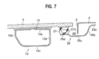
- the rear panel holder 10 has a cross sectional shape having an upper plate 10a, a front plate 10b, a lower plate 10c, and a rear plate 10d.
- the upper plate 10a is attached to a lower surface of a rear edge portion of the roof panel 4 with adhesive 13.
- the front plate 10b extends downward from a front end of the upper plate 10a.
- the lower plate 10c extends rearward from a lower end of the front plate 10b approximately in parallel with the panel surface of the roof panel 4.
- the rear plate 10d extends upward from a rear end of the lower plate 10c to connect with a rear end of the upper plate 10a.
- a closed cross sectional shape having an approximately rectangular shape is formed by these four plates.
- the rear panel holder 10 is attached to the lower surface of the roof panel 4 at a slightly forward location apart from the rear edge of the roof panel 4.
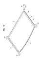
- each of end portions of the front panel holder 8 and each of front end portions of the two side panel holders 9 are connected with each other through a front joint member 29.
- each of end portions of the rear panel holder 10 and each of rear end portions of the two side panel holders 9 are connected with each other through a rear joint member 30.
- Upper surfaces of front joint members 29 and rear joint members 30 are attached to the lower surface of the roof panel 4 at four corners of the roof panel 4 with adhesive or the like.
- the front joint members 29 and the rear joint members 30 are made of material such as plastics.
- a front roof rail 15 is attached to an inner surface of an upper edge portion of the front window 5 with adhesive 14.
- the front roof rail 15 is a member extending in the width direction to give strength to the front window 5, and has an approximately closed cross sectional shape.
- the front roof rail 15 is made of a metal plate, for example, a bended galvanized steel plate formed by bending like roll forming.
- the front roof rail 15 has an approximately closed cross sectional shape having an attaching plate 15a, an upper rear plate 15b, a concave plate 15c, a support plate 15d, a lower rear plate 15e, a lower plate (bottom part) 15f, and a slant plate 15g.
- the attaching plate 15a is attached to the inner surface of the upper edge portion of the front window 5 with the adhesive 14.
- the upper rear plate 15b extends downward and approximately orthogonally to a window surface of the front window 5 from a rear end of the attaching plate 15a.
- the concave plate 15c extends rearward and downward being curved from a lower end of the upper rear plate 15b, and extends rearward and upward to form a concavity projecting downward.
- the support plate 15d extends rearward and approximately horizontally from a rear end of the concave plate 15c.
- the lower rear plate 15e extends downward and approximately vertically from a rear end of the support plate 15d.
- the lower plate 15f extends slantingly forward and downward from a lower end of the lower rear plate 15e.
- the slant plate 15g extends slantingly forward and upward from a front end of the lower plate 15f.
- An upper end of the slant plate 15g is located at the most forward end location of the front roof rail 15 in the cross section. And a part near the upper end of the slant plate 15g is bended rearward and upward to be located adjacently to or to be connected to a front edge of the attaching plate 15a
- the closed cross sectional space 16 of the front roof rail 15 has a front space 16a and a rear space 16b.
- the front space 16a and the rear space 16b communicate with each other through a narrow portion 16c of an approximate border between them.
- the narrow portion 16c is formed by reducing a distance between the concave plate 15c and the slant plate 15g.
- the front space 16a is surrounded mainly by the attaching plate 15a, the upper rear plate 15b, and the slant plate 15g.
- the rear space 16b is surrounded mainly by the support plate 15d, the lower rear plate 15e, and the lower plate 15f.
- the front space 16a is located under the attaching plate 15a for being attached to the front window 5.
- the rear space 16b is communicated with a lower and rear portion of the front space 16a and is located under the front edge of the roof panel 4, that is, under the front panel holder 8, when the opening 3 is closed.
- a joint section 17 between edges of the plate is formed because the front roof rail 15 is a member formed by bending one metal plate as mentioned above.
- Figure 5 shows that the front roof rail 15 is formed so that the joint section 17 is located in the attaching plate 15a.
- the rigidity of the front roof rail 15 is enhanced by sealing the joint section 17 with the adhesive 14.
- a patch member 18 of a separate member may be welded to the attaching plate 15a to seal the joint section 17. In this case of the patch member 18, it is not required to seal with the adhesive 14. Therefore, the front roof rail 15 may be formed so that the joint section 17 is located at some place except the attaching plate 15a.
- a drain channel for draining rain water or the like is equipped under the whole peripheral edge portion of the roof panel 4.
- a front roof stiffener 19 extending in the width direction is equipped over the front roof rail 15.
- the front roof stiffener 19 has a cross sectional shape having a base plate 19a, a side plate 19b, a bottom plate 19c, and a seal attaching plate 19d.
- the base plate 19a is located between the upper edge portion of the front window 5 and the attaching plate 15a of the front roof rail 15.
- the side plate 19b extends downward and approximately orthogonally to the window surface of the front window 5 from a rear end of the base plate 19a.
- the bottom plate 19c extends rearward and approximately horizontally from an end of the side plate 19b.
- the seal attaching plate 19d is bended slightly upward from a rear end of the bottom plate 19c and then extends rearward and approximately horizontally.
- a front end portion of the base plate 19a of the front roof stiffener 19 is fixed to the upper edge portion of the front window 5 and the attaching plate 15a of the front roof rail 15 by interposing the adhesive 14.
- both lower surfaces of a rear portion of the bottom plate 19c and the seal attaching plate 19d are attached to the support plate 15d of the front roof rail 15 by interposing an adhesive 20.
- a seal member 21 extending in the width direction is fixed to an upper surface of the seal attaching plate 19d with adhesive or the like.
- the seal member 21 is made of rubber having a shape such as a hollow closed cross sectional shape.
- the lower plate 8c of the front panel holder 8 is pressed onto the seal member 21 when the opening 3 is closed. Therefore, an area around the front edge of the roof panel 4 becomes watertight. Thus, water is prevented from entering the interior of the vehicle. That is, the front edge portion of the roof panel 4 is placed over the rear space 16b of the front roof rail 15 through the front roof stiffener 19.
- a drain channel 22 is defined by the side plate 19b, the bottom plate 19c, and the front side surface 21 a of the seal member 21. Water dropped in the drain channel 22 is drained out through drain holes (not shown) formed at both end portions of the drain channel 22 in the width direction, and then, is drained out through front pillars.
- a side roof stiffener 23 extending in a front-rear direction of the vehicle is equipped under each side edge of the roof panel 4.
- the side roof stiffener 23 has a cross sectional shape having a connection plate 23a, a first side plate 23b, a bottom plate 23c, a second side plate 23d, and a seal attaching plate 23e.
- the connection plate 23a extends approximately horizontal, and is connected to a body frame of the vehicle not shown.
- the first side plate 23b extends downward and approximately vertically from an end of the connection plate 23a nearer the middle of the vehicle in the width direction.
- the bottom plate 23c extends approximately horizontally from a lower end of the first side plate 23b toward the middle of the vehicle in the width direction.
- the second side plate 23d extends upward and approximately vertically from an end of the bottom plate 23c nearer the middle of the vehicle in the width direction.
- the seal attaching plate 23e extends toward the middle of the vehicle in the width direction from an upper end of the second side plate 23d slantingly slightly upwards.
- a seal member 24 extending in the front-rear direction of the vehicle is fixed to an upper surface of the seal attaching plate 23e with adhesive or the like.
- the seal member 24, the seal member 21 and a seal member 27 described later are one piece member having a rectangle frame shape in plan view.
- the lower plate 9c of the side panel holder 9 is pressed onto the seal member 24 when the opening 3 is closed. Therefore, an area around each side edge of the roof panel 4 becomes watertight. Thus, water is prevented from entering the interior of the vehicle.
- a drain channel 25 is defined by the first side plate 23b, the bottom plate 23c, and the second side plate 23d. Water dropped in the drain channel 25 is drained out through a drain hole (not shown), and then, is drained out through the front pillar, a center pillar, or the like.
- a rear roof stiffener 26 extending in the width direction is equipped under the rear edge of the roof panel 4.
- the rear roof stiffener 26, the front roof stiffener 19, and the side roof stiffeners 23 are one piece member having a rectangle frame shape in plan view.
- the rear roof stiffener 26 has a cross sectional shape having a connection plate 26a, a side plate 26b, a bottom plate 26c, and a seal attaching plate 26d.
- the connection plate 26a extends approximately horizontally, and is connected to a body frame of the vehicle not shown.
- the side plate 26b extends approximately downward from a front end of the connection plate 26a.
- the bottom plate 26c extends forward and approximately horizontally from a lower end of the side plate 26b.
- the seal attaching plate 26d extends forward and approximately horizontally from a front end of the bottom plate 26c through a short slant portion slanting upward from the front end of the bottom plate 26c.
- a seal member 27 extending in the width direction is fixed on an upper surface of the seal attaching plate 26d with adhesive or the like.
- the front panel holder 8 and the side panel holders 9 are pressed onto the seal members 21 and 24, respectively, when the opening 3 is closed.
- the rear panel holder 10 is not pressed onto the seal member 27, but a lower surface of the rear edge portion of the roof panel 4 is pressed onto the seal member 27.
- an area around the rear edge of the roof panel 4 becomes watertight, and, water is prevented from entering the interior of the vehicle.
- a drain channel 28 is defined by the side plate 26b, the bottom plate 26c, and a rear side surface 27a of the seal member 27. Water dropped in the drain channel 28 is drained out through drain holes (not shown) formed at both end portions of the drain channel 28 in the width direction, and then, is drained out through center pillars.
- the lower surface of the roof panel 4 is pressed directly onto the seal member 27 without interposing the rear panel holder 10.
- the side panel holder 9 is pressed onto the seal member 24. Therefore, there exists a distance corresponding to a height of the side panel holder 9 between the roof panel 4 and the seal member 24.
- a distance between the roof panel 4 and the seal member 27 is zero.
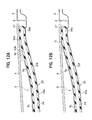
- a part around a rear end of the seal attaching plate 23e of the side roof stiffener 23 is formed to be a slant plate 23f which gradually approaches the roof panel 4 as it goes rearward, as shown in Figure 12A .
- a part around a rear end of the lower plate 9c of the side panel holder 9 is also formed to be a slant plate 9g (refer to Figure 11 also)as it goes rearward so that the part can be pressed onto the seal member 24 following the slant plate 23f to be slant.
- a gap G is generated because of a plate thickness of the lower plate 9c (or 9g) among a rear end surface of the lower plate 9c, the roof panel 4, and the seal member 24.
- a sufficient watertight state may not be obtained.
- no gap G is generated by equipping a rear joint member 30 just behind the side panel holder 9.
- a lower surface 30b of the rear joint member 30 is formed to be a slant surface which becomes flush with a lower surface of the slant plate 9g of the side panel holder 9.
- the slant surface 30b extends rearward up to a location abutting against the lower surface of the roof panel 4 (refer to Figure 11 also).
- the expected watertight performance can be obtained without generating the gap G.
- a rear end of the lower plate 9c (or 9g) cannot be cut in an acute angle so as not to generate the gap G because the side panel holder 9 is made of a metal plate or sheet.
- the rear joint member 30 is made of plastics having an excellent formability, a rear edge 30a of the rear joint member 30 can be easily formed to have a pointed acute angle in side view.
- a left guide frame 31 extending in the front-rear direction of the vehicle is fixed under each of two side edge portions of the roof panel 4.
- the guide frame 31 has a cross sectional shape having a cable channel 33 and a guide rail channel 35.
- the cable channel 33 is a channel to insert thereinto a push-pull cable 32 which can be reciprocated in the front-rear direction by a drive motor not shown.
- the guide rail channel 35 is a channel to guide a drive slider 34 connected to the push-pull cable 32 to slide in the front-rear direction. A connected part between the push-pull cable 32 and the drive slider 34 is not shown.
- the guide frame 31 is made, for example, by extrusion of aluminum alloy.
- the drive slider 34 has a body 34A of a vertical plate standing up vertically or along the guide frame 31, and a plurality of shoes 34B protruding left and right from a lower part of the body 34A at front and rear edge portions of the body 34A.
- the shoes 34B slide in the guide rail channel 35.
- Each shoe 34B may be formed integrally with the body 34A, or may be formed as a separate member.
- a first lift guide channel 36 and a second lift guide channel 37 are formed in the body 34A at a front part thereof and a rear part thereof, respectively. Each channel passes through the body 34A in the width direction (of the vehicle), that is, in a left-right direction of the vehicle.
- the first lift guide channel 36 has a first horizontal stroke 36A extending approximately horizontally, a first slant stroke 36B slantingly extending forward and slightly upward from a front end of the first horizontal stroke 36A, a second horizontal stroke 36C extending approximately horizontally and forward from an upper end of the first slant stroke 36B, and a second slant stroke 36D slantingly extending forward and upward from a front end of the second horizontal stroke 36C.
- the second lift guide channel 37 has a first horizontal stroke 37A extending approximately horizontally, a slant stroke 37B slantingly extending forward and upward from a front end of the first horizontal stroke 37A, and a second horizontal stroke 37C extending approximately horizontally and forward from an upper end of the slant stroke 37B.
- a panel support stay 38 is interposed between the roof panel 4 and the drive slider 34.
- the panel support stay 38 is a vertical plate and has a base plate part 39 at the front half part thereof and a forked part 40 at the rear half part thereof.
- the forked part 40 has an upper part 41 connected to the roof panel 4 and a lower part 42 engaged with the drive slider 34.
- the forked part 40 has an opening facing rearward.
- the upper part 41 extends approximately in the front-rear direction along a lower surface of the roof panel 4.
- One of a plurality of connection pins 43 is connected to the upper part 41 at a rear end portion of the upper part 41.
- the lower part 42 also extends approximately in the front-rear direction and a second lift guide pin 45 is attached to the lower part 42 at a rear end portion of the lower part 42 as described later.
- a part of the side panel holder 9 is formed as the bracket 9f of a vertical plate as mentioned above.
- an upper edge portion of the base plate 39 of the panel support stay 38 and the upper part 41 are connected to and fixed to the bracket 9f by a plurality of connection pins 43.
- the first lift guide pin 44 and the second lift guide pin 45 are attached to a lower front edge portion of the base plate 39 and to a rear edge portion of the lower part 42 of the panel support stay 38, respectively.
- the first lift guide pin 44 and the second lift guide pin 45 are engaged with the first lift guide channel 36 and the second lift guide channel 37 of the drive slider 34, respectively so that the first lift guide pin 44 and the second lift guide pin 45 can slide in the channel 36 and in the channel 37, respectively.
- the panel support stay 38 may be formed integrally with the side panel holder 9, or may be directly attached to the lower surface of the roof panel 4 with adhesive or the like without interposing the side panel holder 9.
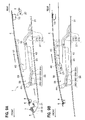
- FIG. 8A shows a state where the opening 3 is closed by the roof panel 4.
- the drive slider 34 is located at the most forward location.
- the first lift guide pin 44 is located at the first horizontal stroke 36A of the first lift guide channel 36
- the second guide pin 45 is located at the first horizontal stroke 37A of the second lift guide channel 37.
- the front panel holder 8 is pressed onto the seal member 21 under the front edge portion of the roof panel 4.
- the side panel holder 9 is pressed onto the seal member 24 under each side edge portion of the roof panel 4 (refer to Figure 4 ). Furthermore, a lower surface of the roof panel 4 is pressed onto the seal member 27 under the rear edge portion of the roof panel 4. As a result, the sufficient watertight state can be secured so that water is prevented from entering the interior of the vehicle through the periphery of the roof panel 4.
- the drive slider 34 moves rearward through the push-pull cable 32 ( Figure 4 ) because of driving force of the motor not shown from the state shown in Figure 8A , so that a lower wall of the first slant stroke 36B of the first lift guide channel 36 pushes up the first lift guide pin 44, and a lower wall of the slant stroke 37B of the second lift guide channel 37 pushes up the second lift guide pin 45.
- the roof panel 4 is moved slightly rearward and is tilted up.
- Figure 8B shows a state where the above tilting up is completed.
- the first lift guide pin 44 is located in the second horizontal stroke 36C of the first lift guide channel 36
- the second lift guide pin 45 is located in the second horizontal stroke 37C of the second lift guide channel 37.
- the drive slider 34 moves furthermore rearward from the state shown in Figure 8B , so that the roof panel 4 moves rearward because a lower wall of the second slant stroke 36D of the first lift guide channel 36 pushes the first lift guide pin 44 rearward as shown in Figure 9A .
- Figure 9B shows a state where the roof panel 4 has moved to the rearmost location so that the opening 3 is fully opened.
- the upper part 41 of the panel support stay 38 is located over the outer roof panel 2 behind the opening 3, and the lower part 42 is located under the outer roof panel 2 behind the opening 3. That is, the forked part 40 of the panel support stay 38 is located to sandwich the outer roof panel 2 behind the opening 3 vertically.
- the second lift guide pin 45 is located at a more rearward location than a rear edge of the opening 3.
- Two pins connecting a panel support stay and a slider in a prior structure described in Japanese Patent Laid-open Publication No. 2005-41345 are located at a more forward location than a rear edge of the opening when the opening is fully opened.
- the forward pin is equipped at a more forward location, for example, by extending a front end of each guide rail forward, it is difficult to enlarge a distance between the two pins, that is, a support span to support a weight of the roof panel supported by the slider.
- the two pins are located at more forward locations excessively than a gravitational center of the roof panel. Therefore, a large load is applied on the panel support stay because of a large moment.
- the second lift guide pin 45 is located at a more rearward location than the rear edge of the opening 3 when the opening 3 is fully opened. That is, a part of the engaging portions between the panel support stay 38 and the drive slider 34, which is a part of support portions to support the weight of the roof panel 4, is located at a more rearward location than the rear edge of the opening 3. Therefore, a support span S (refer to Figure 3 ) to support the roof panel 4 can be kept long while opening quantity of the opening 3 is fully kept without taking specific measures, for example, extending the front end of the guide frame 31 forward. Furthermore, the load applied to the panel support stay 38 can be decreased because one of the support portions for the weight of the roof panel 4 is located at a more rearward location than the prior structure to be closer to the gravitational center of the roof panel 4.
- the panel support stay 38 is formed to have the forked part 40 in a forked shape.
- the upper part 41 of the forked part 40 is connected to the roof panel 4 and the lower part 42 of the forked part 40 is engaged with the drive slider 34.
- the panel support stay 38 has the opening between the upper part 41 and the lower part 42 so that the opening faces rearward.
- the forked part 40 is located to sandwich the outer roof panel 2 behind the opening 3 vertically when the opening 3 is fully opened, as shown in Figure 9B . Therefore, the simple panel support stay 38 can be formed and the support span S for the roof panel 4 can become long.
- the sunroof apparatus 1 has an opening 3 in the outer roof panel 2 to be closed by the structure that the front edge of the roof panel 4 is located at a location adjacent to the upper edge of the front window 5 without interposing the outer roof panel 2 between the front edge of the roof panel 4 and the upper edge of the front window 5. That is, there exists no outer roof panel 2 between the front edge of the roof panel 4 and the upper edge of the front window 5 according to the sunroof apparatus 1 of the present embodiment, so a field of view in a slantingly forward and upward direction can be improved by that much.
- prior arts for example, Japanese Patent Laid-open Publication No.
- the front roof rail is made of an upper member and a lower member, that is, made of two members.
- the front roof rail 15 is made of a metal plate bended so as to have an approximately closed cross sectional shape. Therefore, no flange is needed. As a result, the field of view in the slantingly forward and upward direction can be enlarged by that much.
- the front roof rail 15 is located so that at least a part (front space 16a) of the closed cross sectional space 16 is located under a portion of the front window 5 which the front roof rail 15 is attached to. Therefore, the front window 5 can be sufficiently reinforced by the front roof rail 15.
- the rigidity (specifically, torsional rigidity) of the front roof rail 15 can be further enhanced.
- the rigidity of the front roof rail 15 can be easily enhanced by a simple structure closing also the joint section 17 with the adhesive 14.
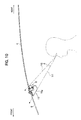
- the load from the roof panel 4 can be effectively received by the rigidity of the closed cross sectional space 16 in a case where the front edge portion of the roof panel 4 is located over the closed cross sectional space 16 of the front roof rail 15, specifically, the rear space 16b when the opening 3 is closed. Furthermore, a flange or the like to receive the front edge portion of the roof panel 4 is not needed to be specifically formed, so a structure around the front edge portion of the roof panel 4 becomes compact. Therefore, a crossing angle ⁇ between view lines V1 and V2 becomes small and the field of view in the slantingly forward and upward direction can be enlarged, as shown in Figure 10 .
- the front roof rail 15 has a slant plate 15g which extends slantingly forward and upward from a lower end thereof, and is in a lower front area of the front roof rail 15, an upper end of the slant plate 15g being located at the most forward end location in the approximately closed cross sectional shape of the front roof rail 15, the view line V1 seen from a seated person can be kept along a surface of the slant plate 15g as shown in Figure 10 . Therefore, the field of view for the front window 5 can be enlarged.
- the seal member 24 is pressed onto the slant surface 30b of the rear joint member 30 which is made of plastics and has the slant surface 30b slanting in an upper and rearward direction up to the rear edge 30a of the rear joint member 30, the rear edge 30a being approximately in contact with the lower surface of the roof panel 4, the seal member 24 extending up to the lower surface of the rear edge portion of the roof panel 4 from a part abutting against the side panel holder 9 so that the seal member 24 abuts against the lower surface of the rear edge portion of the roof panel 4, the gap G as shown in Figure 12B is prevented from generating between the roof panel 4 and the seal member 24. Therefore, a watertight state by using the seal member 24 can be enhanced thanks to the rear joint member 30.
- each of the seal member 21 and 27 operates as a part of walls of the drain channel 22 or the drain channel 28
- a drain structure shares a partial structure thereof with a watertight structure. Therefore, structures around the drain channels 22 and 28 are compact. Furthermore, cross sectional shapes of the front roof stiffener 19 and the rear roof stiffener 26 are also simple.
- the seal member 24 also may be adopted as a part of side walls of the drain channel 25 in the case of the side roof stiffener 23.
- the drive slider 34 is formed to be one piece.
- the drive slider 34 may be formed to have a plurality of pieces.
Landscapes
- Engineering & Computer Science (AREA)
- Mechanical Engineering (AREA)
- Body Structure For Vehicles (AREA)
- Seal Device For Vehicle (AREA)
- Power-Operated Mechanisms For Wings (AREA)
- Roof Covering Using Slabs Or Stiff Sheets (AREA)
Abstract
Description
- The present invention relates to a sunroof apparatus for a vehicle.
- A sunroof apparatus described in the patent document 1 listed below exemplifies a prior sunroof apparatus. This sunroof apparatus includes a movable roof panel installed in an opening formed in a fixed outer roof panel of a vehicle, a drive slider to move in a front-rear direction of the vehicle, and a panel support stay interposing between the movable roof panel and the drive slider. The panel support stay moves rearward while inclining as the drive slider slides rearward. Hereby, the movable roof panel is tilted up and moves rearward.
- Furthermore, the patent document 1 discloses a technology to protrude a front end portion of a guide rail for guiding the drive slider to a more forward location than a drainage ditch in a front frame. According to this technology, a span between support portions of the panel support stay for supporting the roof panel can be enlarged without sacrificing an open degree of the opening as much as the front end portion of the guide rail is protruded. Therefore, the supporting stiffness for supporting the movable roof panel can be enhanced.
- Patent document 1: Japanese Patent Laid-Open Publication No.
2005-41345 - However, in some cases, the front end portion of the guide rail cannot be protruded so much forward because the fixed outer roof panel around the front end of the guide rail is a panel with a narrow width along the front-rear direction of the vehicle.
- At least the preferred embodiments of the present invention seek to solve such a problem. It is an object of at least the preferred embodiments of the present invention to provide a sunroof apparatus capable of enlarging a span for supporting the movable roof panel regardless of the protruding structure of the front end portion of the guide rail.
- The present invention provides a sunroof apparatus comprising a movable roof panel installed in an opening formed in a fixed outer roof panel of a vehicle, a drive slider to move in a front-rear direction of the vehicle along a fixed guide frame, and a panel support stay interposing between the movable roof panel and the drive slider to support the roof panel, the movable roof panel being tilted up and moving rearward by a rearward moving of the panel support stay while the panel support stay is in an inclined position, as the drive slider slides rearward,
wherein a part of a plurality of engagement portions between the panel support stay and the drive slider is located at a more rearward location than a rear edge of the opening when the opening is fully opened. - According to the above sunroof apparatus, the span for supporting the movable roof panel can be enlarged while an open degree of the opening is kept large by locating a part of the plurality of engagement portions between the panel support stay and the drive slider more rearward than the rear edge of the opening when the opening is fully opened. The plurality of engagement portions are support portions to support a load of the movable roof panel. And a part of support portions (or the plurality of engagement portions) to support a load of the roof panel is located rearward in comparison with the prior structure, so that the rearward part of support portions comes near the center of the gravity of the movable roof panel. Therefore, a load to the panel support stay becomes low.
- And, the present invention provides also a sunroof apparatus, wherein the panel support stay includes a forked part having an upper part to be connected to the roof panel and a lower part to be engaged with the drive slider so as to form an opening facing rearward between the upper part and the lower part, and wherein the forked part is located so that the upper and the lower parts thereof face each other vertically across the fixed outer roof panel located behind the opening in the fixed outer roof panel when the opening in the fixed outer roof panel is fully opened.
- According to the above sunroof apparatus, the span for supporting the movable roof panel can be enlarged with a simple structure of the panel support stay.
- According to the present invention, the span for supporting the roof panel can be enlarged regardless of the structure around or protruding of the front end portion of the guide frame.
- Certain preferred embodiments of the present invention will now be described in greater detail by way of example only and with reference to the accompanying drawings, in which:
-
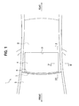
FIG. 1 is a plan view of a sunroof apparatus of the present embodiment according to the present invention; -
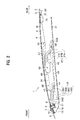
FIG. 2 is an enlarged longitudinal sectional view taken along the line II-II shown inFIG. 1 ; -
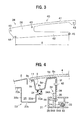
FIG. 3 is a side view of a panel support stay; -
FIG. 4 is an enlarged cross sectional view taken along the line IV-IV shown inFIG. 1 ; -
FIG. 5 is an enlarged longitudinal sectional view around the front edge of the movable roof panel shown inFIG. 2 ; -
FIG. 6 is another enlarged longitudinal sectional view around the front edge of the movable roof panel according to another embodiment different fromFIG. 5 ; -
FIG. 7 is an enlarged longitudinal sectional view around the rear edge of the movable roof panel shown inFIG. 2 ; -
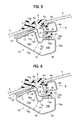
FIG. 8A is a longitudinal sectional view for explaining the action of the sunroof apparatus of the present embodiment; -
FIG. 8B is another longitudinal sectional view for explaining the action of the sunroof apparatus of the present embodiment; -
FIG. 9A is further another longitudinal sectional view for explaining the action of the sunroof apparatus of the present embodiment; -
FIG. 9B is another longitudinal sectional view for explaining the action of the sunroof apparatus of the present embodiment; -
FIG. 10 is a longitudinal sectional view for explaining a field of view around a front roof rail; -
FIG. 11 is a perspective view showing a front panel holder, side panel holders, a rear panel holder, and front and rear joint members for connecting them together; -
FIG. 12A is a longitudinal sectional view around the rear edge of the movable roof panel showing a watertight state of a seal member with an interposition of a rear joint member; and -
FIG. 12B is a longitudinal sectional view around the rear edge of the movable roof panel showing a watertight state of a seal member without the interposition of the rear joint member shown inFIG. 12A . - As shown in
Figure 1 , a sunroof apparatus 1 of the present embodiment according to the present invention is installed in anopening 3 formed in a fixed outer roof panel 2 (hereinafter, outer roof panel 2) of a vehicle, and is configured to be capable of opening and closing theopening 3. The sunroof apparatus 1 comprises a movable roof panel 4 (hereinafter, sometimes, roof panel 4) which is an outer roof panel to move backward in a tilted position while the opening is being opened. Theroof panel 4 is made of, for example, glass or plastics. - The
opening 3 has a rectangular shape. Theopening 3 is made by cutting off a front area of theouter roof panel 2 of a fixed roof. In the prior art, a movable roof panel is adjacent to a rear edge of theouter roof panel 2 in front of theopening 3 when the opening is closed. On the other hand, a front edge of theroof panel 4 when theopening 3 is closed (hereinafter, sometimes, closed roof panel 4) shown inFigures 1 and2 , is located at a location adjacent to an upper edge of afront window 5 without theouter roof panel 2 between them. However, the closedroof panel 4 is located adjacently to theouter roof panel 2 of the fixed roof at left and right side edges and a rear edge of theroof panel 4. Strictly speaking, aweather strip 6 made of rubber or the like and aweather strip 7 made of rubber or the like slightly abut against each other as shown inFigure 2 . Theweather strip 6 is attached to a front edge portion of theroof panel 4, and theweather strip 7 is attached to an upper edge portion of thefront window 5. Thus, an outer surface of theroof panel 4 near the front edge thereof and an outer surface of thefront window 5 near the upper edge thereof are disposed to be a flush form. As shown inFigure 5 , theweather strip 6 has abase part 6a and alip part 6b. Thebase part 6a is attached to the front edge portion of theroof panel 4, and thelip part 6b extends forward like a thin tongue from the front end of thebase part 6a. The front end portion of thelip part 6b slightly abuts against a rear upper surface of theweather strip 7. - With reference to
Figures 2 and11 , afront panel holder 8,side panel holders 9 and arear panel holder 10 are attached with adhesive or the like to an inner surface of theroof panel 4 at the front edge, both side edges, and the rear edge, of theroof panel 4, respectively, in order to mainly reinforce theroof panel 4. Thefront panel holder 8,side panel holders 9 and therear panel holder 10 are made of, for example, metal member like a plating steel plate. - As shown in
Figure 5 , thefront panel holder 8 has a cross sectional shape having anupper plate part 8a, arear plate part 8b, alower plate part 8c, and afront plate part 8d. Hereinafter, a word of "part" will be omitted from theseparts upper plate 8a extends rearward and slightly upward to follow a slope of the front edge portion of theroof panel 4. Therear plate 8b extends downward and approximately orthogonally to a panel surface of theroof panel 4 from a rear end of theupper plate 8a. Thelower plate 8c extends forward and approximately horizontally from a lower end of therear plate 8b. Thefront plate 8d extends upward and approximately orthogonally to the panel surface of theroof panel 4 from a front end of thelower plate 8c, and an upper portion of thefront plate 8d is embedded in thebase portion 6a of theweather strip 6. A part near a front end of theupper plate 8a is formed to have an approximate U shape. A bottom of the U shape is protruded downward, and thus the part near a front end of theupper plate 8a is engaged with a part of thebase 6a of theweather strip 6. As mentioned above, thefront panel holder 8 is attached to a lower surface of theroof panel 4 through theweather strip 6. In addition thereto or in place thereof, thefront panel holder 8 may be attached to the lower surface of theroof panel 4 with adhesive. - As shown in
Figure 4 , theside panel holder 9 has a cross sectional shape having a firstupper plate 9a, afirst side plate 9b, alower plate 9c, asecond side plate 9d, a secondupper plate 9e, and abracket 9f. The firstupper plate 9a is attached to a lower surface of a side edge portion of theroof panel 4 withadhesive 11. Thefirst side plate 9b extends downward and approximately orthogonally to the panel surface of theroof panel 4 from an end of the firstupper plate 9a nearer a middle of the vehicle in a width direction of the vehicle (hereinafter, a word of "vehicle" will be omitted). Thelower plate 9c extends slightly upward and toward the middle of the vehicle in the width direction from a lower end of thefirst side plate 9b, so that thelower plate 9c slightly inclines so as to be parallel with the panel surface of theroof panel 4. Thesecond side plate 9d extends upward from an end of thelower plate 9c nearer the middle of the vehicle in the width direction. The secondupper plate 9e extends toward the middle of the vehicle in the width direction from an upper end of thesecond side plate 9d, and is attached to the lower surface of theroof panel 4 withadhesive 12. Thebracket 9f extends downward, that is, extends approximately vertically from an end of the secondupper plate 9e nearer the middle of the vehicle in the width direction so that thebracket 9f has a shape of an approximately vertical plate extending downward. A closed space in a cross section is formed under theroof panel 4 by thefirst side plate 9b, thelower plate 9c, and thesecond side plate 9d in cooperation with theroof panel 4. This closed shape structure in the cross section serves as reinforcement. Thebracket 9f is connected with the panel support stay 38 as described later. - As shown in
Figure 7 , therear panel holder 10 has a cross sectional shape having anupper plate 10a, afront plate 10b, alower plate 10c, and arear plate 10d. Theupper plate 10a is attached to a lower surface of a rear edge portion of theroof panel 4 withadhesive 13. Thefront plate 10b extends downward from a front end of theupper plate 10a. Thelower plate 10c extends rearward from a lower end of thefront plate 10b approximately in parallel with the panel surface of theroof panel 4. Therear plate 10d extends upward from a rear end of thelower plate 10c to connect with a rear end of theupper plate 10a. A closed cross sectional shape having an approximately rectangular shape is formed by these four plates. Therear panel holder 10 is attached to the lower surface of theroof panel 4 at a slightly forward location apart from the rear edge of theroof panel 4. - As shown in
Figure 11 , each of end portions of thefront panel holder 8 and each of front end portions of the twoside panel holders 9 are connected with each other through a frontjoint member 29. And each of end portions of therear panel holder 10 and each of rear end portions of the twoside panel holders 9 are connected with each other through a rearjoint member 30. Upper surfaces of frontjoint members 29 and rearjoint members 30 are attached to the lower surface of theroof panel 4 at four corners of theroof panel 4 with adhesive or the like. The frontjoint members 29 and the rearjoint members 30 are made of material such as plastics. - As shown in
Figure 2 , afront roof rail 15 is attached to an inner surface of an upper edge portion of thefront window 5 withadhesive 14. Thefront roof rail 15 is a member extending in the width direction to give strength to thefront window 5, and has an approximately closed cross sectional shape. Furthermore, thefront roof rail 15 is made of a metal plate, for example, a bended galvanized steel plate formed by bending like roll forming. - As shown in
Figure 5 , thefront roof rail 15 has an approximately closed cross sectional shape having an attachingplate 15a, an upperrear plate 15b, aconcave plate 15c, asupport plate 15d, a lowerrear plate 15e, a lower plate (bottom part) 15f, and aslant plate 15g. The attachingplate 15a is attached to the inner surface of the upper edge portion of thefront window 5 with the adhesive 14. The upperrear plate 15b extends downward and approximately orthogonally to a window surface of thefront window 5 from a rear end of the attachingplate 15a. Theconcave plate 15c extends rearward and downward being curved from a lower end of the upperrear plate 15b, and extends rearward and upward to form a concavity projecting downward. Thesupport plate 15d extends rearward and approximately horizontally from a rear end of theconcave plate 15c. The lowerrear plate 15e extends downward and approximately vertically from a rear end of thesupport plate 15d. Thelower plate 15f extends slantingly forward and downward from a lower end of the lowerrear plate 15e. Theslant plate 15g extends slantingly forward and upward from a front end of thelower plate 15f. An upper end of theslant plate 15g is located at the most forward end location of thefront roof rail 15 in the cross section. And a part near the upper end of theslant plate 15g is bended rearward and upward to be located adjacently to or to be connected to a front edge of the attachingplate 15a - In accordance with the cross sectional shape of the
front roof rail 15 mentioned above, the closed crosssectional space 16 of thefront roof rail 15 has afront space 16a and arear space 16b. Thefront space 16a and therear space 16b communicate with each other through anarrow portion 16c of an approximate border between them. Thenarrow portion 16c is formed by reducing a distance between theconcave plate 15c and theslant plate 15g. Thefront space 16a is surrounded mainly by the attachingplate 15a, the upperrear plate 15b, and theslant plate 15g. And therear space 16b is surrounded mainly by thesupport plate 15d, the lowerrear plate 15e, and thelower plate 15f. Thefront space 16a is located under the attachingplate 15a for being attached to thefront window 5. Therear space 16b is communicated with a lower and rear portion of thefront space 16a and is located under the front edge of theroof panel 4, that is, under thefront panel holder 8, when theopening 3 is closed. - A
joint section 17 between edges of the plate is formed because thefront roof rail 15 is a member formed by bending one metal plate as mentioned above.Figure 5 shows that thefront roof rail 15 is formed so that thejoint section 17 is located in the attachingplate 15a. The rigidity of thefront roof rail 15 is enhanced by sealing thejoint section 17 with the adhesive 14. As another example, apatch member 18 of a separate member may be welded to the attachingplate 15a to seal thejoint section 17. In this case of thepatch member 18, it is not required to seal with the adhesive 14. Therefore, thefront roof rail 15 may be formed so that thejoint section 17 is located at some place except the attachingplate 15a. - Then, a drain channel for draining rain water or the like is equipped under the whole peripheral edge portion of the
roof panel 4. At first, as shown inFigure 5 , afront roof stiffener 19 extending in the width direction is equipped over thefront roof rail 15. Thefront roof stiffener 19 has a cross sectional shape having abase plate 19a, aside plate 19b, abottom plate 19c, and aseal attaching plate 19d. Thebase plate 19a is located between the upper edge portion of thefront window 5 and the attachingplate 15a of thefront roof rail 15. Theside plate 19b extends downward and approximately orthogonally to the window surface of thefront window 5 from a rear end of thebase plate 19a. Thebottom plate 19c extends rearward and approximately horizontally from an end of theside plate 19b. Theseal attaching plate 19d is bended slightly upward from a rear end of thebottom plate 19c and then extends rearward and approximately horizontally. A front end portion of thebase plate 19a of thefront roof stiffener 19 is fixed to the upper edge portion of thefront window 5 and the attachingplate 15a of thefront roof rail 15 by interposing the adhesive 14. And both lower surfaces of a rear portion of thebottom plate 19c and theseal attaching plate 19d are attached to thesupport plate 15d of thefront roof rail 15 by interposing an adhesive 20. - A
seal member 21 extending in the width direction is fixed to an upper surface of theseal attaching plate 19d with adhesive or the like. Theseal member 21 is made of rubber having a shape such as a hollow closed cross sectional shape. Thelower plate 8c of thefront panel holder 8 is pressed onto theseal member 21 when theopening 3 is closed. Therefore, an area around the front edge of theroof panel 4 becomes watertight. Thus, water is prevented from entering the interior of the vehicle. That is, the front edge portion of theroof panel 4 is placed over therear space 16b of thefront roof rail 15 through thefront roof stiffener 19. And, adrain channel 22 is defined by theside plate 19b, thebottom plate 19c, and the front side surface 21 a of theseal member 21. Water dropped in thedrain channel 22 is drained out through drain holes (not shown) formed at both end portions of thedrain channel 22 in the width direction, and then, is drained out through front pillars. - As shown in
Figure 4 , aside roof stiffener 23 extending in a front-rear direction of the vehicle is equipped under each side edge of theroof panel 4. Theside roof stiffener 23 has a cross sectional shape having aconnection plate 23a, afirst side plate 23b, abottom plate 23c, asecond side plate 23d, and aseal attaching plate 23e. Theconnection plate 23a extends approximately horizontal, and is connected to a body frame of the vehicle not shown. Thefirst side plate 23b extends downward and approximately vertically from an end of theconnection plate 23a nearer the middle of the vehicle in the width direction. Thebottom plate 23c extends approximately horizontally from a lower end of thefirst side plate 23b toward the middle of the vehicle in the width direction. Thesecond side plate 23d extends upward and approximately vertically from an end of thebottom plate 23c nearer the middle of the vehicle in the width direction. Theseal attaching plate 23e extends toward the middle of the vehicle in the width direction from an upper end of thesecond side plate 23d slantingly slightly upwards. - A
seal member 24 extending in the front-rear direction of the vehicle is fixed to an upper surface of theseal attaching plate 23e with adhesive or the like. In addition, theseal member 24, theseal member 21 and aseal member 27 described later are one piece member having a rectangle frame shape in plan view. Thelower plate 9c of theside panel holder 9 is pressed onto theseal member 24 when theopening 3 is closed. Therefore, an area around each side edge of theroof panel 4 becomes watertight. Thus, water is prevented from entering the interior of the vehicle. And adrain channel 25 is defined by thefirst side plate 23b, thebottom plate 23c, and thesecond side plate 23d. Water dropped in thedrain channel 25 is drained out through a drain hole (not shown), and then, is drained out through the front pillar, a center pillar, or the like. - As shown in
Figure 7 , arear roof stiffener 26 extending in the width direction is equipped under the rear edge of theroof panel 4. Therear roof stiffener 26, thefront roof stiffener 19, and theside roof stiffeners 23 are one piece member having a rectangle frame shape in plan view. Therear roof stiffener 26 has a cross sectional shape having aconnection plate 26a, aside plate 26b, abottom plate 26c, and aseal attaching plate 26d. Theconnection plate 26a extends approximately horizontally, and is connected to a body frame of the vehicle not shown. Theside plate 26b extends approximately downward from a front end of theconnection plate 26a. Thebottom plate 26c extends forward and approximately horizontally from a lower end of theside plate 26b. Theseal attaching plate 26d extends forward and approximately horizontally from a front end of thebottom plate 26c through a short slant portion slanting upward from the front end of thebottom plate 26c. - A
seal member 27 extending in the width direction is fixed on an upper surface of theseal attaching plate 26d with adhesive or the like. As mentioned above, regarding the front edge portion and the side edge portions of theroof panel 4, thefront panel holder 8 and theside panel holders 9 are pressed onto theseal members opening 3 is closed. However, regarding the rear edge portion of theroof panel 4, therear panel holder 10 is not pressed onto theseal member 27, but a lower surface of the rear edge portion of theroof panel 4 is pressed onto theseal member 27. Thus, an area around the rear edge of theroof panel 4 becomes watertight, and, water is prevented from entering the interior of the vehicle. Adrain channel 28 is defined by theside plate 26b, thebottom plate 26c, and arear side surface 27a of theseal member 27. Water dropped in thedrain channel 28 is drained out through drain holes (not shown) formed at both end portions of thedrain channel 28 in the width direction, and then, is drained out through center pillars. - Regarding an area around the rear edge of the
roof panel 4, the lower surface of theroof panel 4 is pressed directly onto theseal member 27 without interposing therear panel holder 10. As a result, there is a following problem. Regarding the side edge portions of theroof panel 4, as shown inFigure 4 , theside panel holder 9 is pressed onto theseal member 24. Therefore, there exists a distance corresponding to a height of theside panel holder 9 between theroof panel 4 and theseal member 24. On the other hand, as shown inFigure 7 , a distance between theroof panel 4 and theseal member 27 is zero. Therefore, regarding a part around a rear end of theseal attaching plate 23e of theside roof stiffener 23, the part is formed to be aslant plate 23f which gradually approaches theroof panel 4 as it goes rearward, as shown inFigure 12A . In the consequence, a part around a rear end of thelower plate 9c of theside panel holder 9 is also formed to be aslant plate 9g (refer toFigure 11 also)as it goes rearward so that the part can be pressed onto theseal member 24 following theslant plate 23f to be slant. - In a case where the
side panel holder 9 is extended up to a more rearward location than the case ofFigure 12A as shown inFigure 12B , a gap G is generated because of a plate thickness of thelower plate 9c (or 9g) among a rear end surface of thelower plate 9c, theroof panel 4, and theseal member 24. Thus, a sufficient watertight state may not be obtained. On the other hand, as shown inFigure 12A , no gap G is generated by equipping a rearjoint member 30 just behind theside panel holder 9. Alower surface 30b of the rearjoint member 30 is formed to be a slant surface which becomes flush with a lower surface of theslant plate 9g of theside panel holder 9. Theslant surface 30b extends rearward up to a location abutting against the lower surface of the roof panel 4 (refer toFigure 11 also). As a result, the expected watertight performance can be obtained without generating the gap G. A rear end of thelower plate 9c (or 9g) cannot be cut in an acute angle so as not to generate the gap G because theside panel holder 9 is made of a metal plate or sheet. On the other hand, in a case where the rearjoint member 30 is made of plastics having an excellent formability, arear edge 30a of the rearjoint member 30 can be easily formed to have a pointed acute angle in side view. - Next, an open-and-close mechanism of the
roof panel 4 will be described hereinafter.
As shown inFigure 4 , aleft guide frame 31 extending in the front-rear direction of the vehicle is fixed under each of two side edge portions of theroof panel 4. Theguide frame 31 has a cross sectional shape having acable channel 33 and aguide rail channel 35. Thecable channel 33 is a channel to insert thereinto a push-pull cable 32 which can be reciprocated in the front-rear direction by a drive motor not shown. Theguide rail channel 35 is a channel to guide adrive slider 34 connected to the push-pull cable 32 to slide in the front-rear direction. A connected part between the push-pull cable 32 and thedrive slider 34 is not shown. Theguide frame 31 is made, for example, by extrusion of aluminum alloy. - The
drive slider 34 has abody 34A of a vertical plate standing up vertically or along theguide frame 31, and a plurality ofshoes 34B protruding left and right from a lower part of thebody 34A at front and rear edge portions of thebody 34A. Theshoes 34B slide in theguide rail channel 35. Eachshoe 34B may be formed integrally with thebody 34A, or may be formed as a separate member. As shown inFigure 2 , a firstlift guide channel 36 and a secondlift guide channel 37 are formed in thebody 34A at a front part thereof and a rear part thereof, respectively. Each channel passes through thebody 34A in the width direction (of the vehicle), that is, in a left-right direction of the vehicle. - The first
lift guide channel 36 has a firsthorizontal stroke 36A extending approximately horizontally, afirst slant stroke 36B slantingly extending forward and slightly upward from a front end of the firsthorizontal stroke 36A, a secondhorizontal stroke 36C extending approximately horizontally and forward from an upper end of thefirst slant stroke 36B, and asecond slant stroke 36D slantingly extending forward and upward from a front end of the secondhorizontal stroke 36C. The secondlift guide channel 37 has a firsthorizontal stroke 37A extending approximately horizontally, aslant stroke 37B slantingly extending forward and upward from a front end of the firsthorizontal stroke 37A, and a secondhorizontal stroke 37C extending approximately horizontally and forward from an upper end of theslant stroke 37B. - A panel support stay 38 is interposed between the
roof panel 4 and thedrive slider 34. With reference toFigures 2 and3 , the panel support stay 38 is a vertical plate and has abase plate part 39 at the front half part thereof and a forkedpart 40 at the rear half part thereof. The forkedpart 40 has anupper part 41 connected to theroof panel 4 and alower part 42 engaged with thedrive slider 34. The forkedpart 40 has an opening facing rearward. Theupper part 41 extends approximately in the front-rear direction along a lower surface of theroof panel 4. One of a plurality of connection pins 43 is connected to theupper part 41 at a rear end portion of theupper part 41. Thelower part 42 also extends approximately in the front-rear direction and a secondlift guide pin 45 is attached to thelower part 42 at a rear end portion of thelower part 42 as described later. - In
Figure 4 , a part of theside panel holder 9 is formed as thebracket 9f of a vertical plate as mentioned above. As shown inFigure 2 , an upper edge portion of thebase plate 39 of the panel support stay 38 and theupper part 41 are connected to and fixed to thebracket 9f by a plurality of connection pins 43. The firstlift guide pin 44 and the secondlift guide pin 45 are attached to a lower front edge portion of thebase plate 39 and to a rear edge portion of thelower part 42 of thepanel support stay 38, respectively. The firstlift guide pin 44 and the secondlift guide pin 45 are engaged with the firstlift guide channel 36 and the secondlift guide channel 37 of thedrive slider 34, respectively so that the firstlift guide pin 44 and the secondlift guide pin 45 can slide in thechannel 36 and in thechannel 37, respectively. - In addition, the panel support stay 38 may be formed integrally with the
side panel holder 9, or may be directly attached to the lower surface of theroof panel 4 with adhesive or the like without interposing theside panel holder 9. - An operation of the sunroof apparatus 1 will be described mainly with reference to
Figures 8A, 8B ,9A and 9B . Theside panel holder 9 is omitted inFigures 8A, 8B ,9A and 9B .
Figure 8A shows a state where theopening 3 is closed by theroof panel 4. On this occasion, thedrive slider 34 is located at the most forward location. And the firstlift guide pin 44 is located at the firsthorizontal stroke 36A of the firstlift guide channel 36, and thesecond guide pin 45 is located at the firsthorizontal stroke 37A of the secondlift guide channel 37. Thefront panel holder 8 is pressed onto theseal member 21 under the front edge portion of theroof panel 4. Theside panel holder 9 is pressed onto theseal member 24 under each side edge portion of the roof panel 4 (refer toFigure 4 ). Furthermore, a lower surface of theroof panel 4 is pressed onto theseal member 27 under the rear edge portion of theroof panel 4. As a result, the sufficient watertight state can be secured so that water is prevented from entering the interior of the vehicle through the periphery of theroof panel 4. - The
drive slider 34 moves rearward through the push-pull cable 32 (Figure 4 ) because of driving force of the motor not shown from the state shown inFigure 8A , so that a lower wall of thefirst slant stroke 36B of the firstlift guide channel 36 pushes up the firstlift guide pin 44, and a lower wall of theslant stroke 37B of the secondlift guide channel 37 pushes up the secondlift guide pin 45. Thus, theroof panel 4 is moved slightly rearward and is tilted up.Figure 8B shows a state where the above tilting up is completed. On this occasion, the firstlift guide pin 44 is located in the secondhorizontal stroke 36C of the firstlift guide channel 36, and the secondlift guide pin 45 is located in the secondhorizontal stroke 37C of the secondlift guide channel 37. - The
drive slider 34 moves furthermore rearward from the state shown inFigure 8B , so that theroof panel 4 moves rearward because a lower wall of thesecond slant stroke 36D of the firstlift guide channel 36 pushes the firstlift guide pin 44 rearward as shown inFigure 9A . -
Figure 9B shows a state where theroof panel 4 has moved to the rearmost location so that theopening 3 is fully opened. On this occasion, theupper part 41 of the panel support stay 38 is located over theouter roof panel 2 behind theopening 3, and thelower part 42 is located under theouter roof panel 2 behind theopening 3. That is, the forkedpart 40 of the panel support stay 38 is located to sandwich theouter roof panel 2 behind theopening 3 vertically. As shown clearly inFigure 9B , the secondlift guide pin 45 is located at a more rearward location than a rear edge of theopening 3. - Two pins connecting a panel support stay and a slider in a prior structure described in Japanese Patent Laid-open Publication No.
2005-41345 - On the other hand, in the present embodiment, the second
lift guide pin 45 is located at a more rearward location than the rear edge of theopening 3 when theopening 3 is fully opened. That is, a part of the engaging portions between the panel support stay 38 and thedrive slider 34, which is a part of support portions to support the weight of theroof panel 4, is located at a more rearward location than the rear edge of theopening 3. Therefore, a support span S (refer toFigure 3 ) to support theroof panel 4 can be kept long while opening quantity of theopening 3 is fully kept without taking specific measures, for example, extending the front end of theguide frame 31 forward. Furthermore, the load applied to the panel support stay 38 can be decreased because one of the support portions for the weight of theroof panel 4 is located at a more rearward location than the prior structure to be closer to the gravitational center of theroof panel 4. - Furthermore, the panel support stay 38 is formed to have the forked
part 40 in a forked shape. Theupper part 41 of the forkedpart 40 is connected to theroof panel 4 and thelower part 42 of the forkedpart 40 is engaged with thedrive slider 34. And the panel support stay 38 has the opening between theupper part 41 and thelower part 42 so that the opening faces rearward. The forkedpart 40 is located to sandwich theouter roof panel 2 behind theopening 3 vertically when theopening 3 is fully opened, as shown inFigure 9B . Therefore, the simple panel support stay 38 can be formed and the support span S for theroof panel 4 can become long. - As mentioned above, the sunroof apparatus 1 has an
opening 3 in theouter roof panel 2 to be closed by the structure that the front edge of theroof panel 4 is located at a location adjacent to the upper edge of thefront window 5 without interposing theouter roof panel 2 between the front edge of theroof panel 4 and the upper edge of thefront window 5. That is, there exists noouter roof panel 2 between the front edge of theroof panel 4 and the upper edge of thefront window 5 according to the sunroof apparatus 1 of the present embodiment, so a field of view in a slantingly forward and upward direction can be improved by that much. In prior arts (for example, Japanese Patent Laid-open Publication No.2010-163112 front roof rail 15 according to the present embodiment is made of a metal plate bended so as to have an approximately closed cross sectional shape. Therefore, no flange is needed. As a result, the field of view in the slantingly forward and upward direction can be enlarged by that much. Thefront roof rail 15 is located so that at least a part (front space 16a) of the closed crosssectional space 16 is located under a portion of thefront window 5 which thefront roof rail 15 is attached to. Therefore, thefront window 5 can be sufficiently reinforced by thefront roof rail 15. - In a case where the
joint section 17 of thefront roof rail 15 is closed with thepatch member 18 as shown inFigure 6 , the rigidity (specifically, torsional rigidity) of thefront roof rail 15 can be further enhanced. In the case where thefront roof rail 15 is attached to thefront window 5 with the adhesive 14 as shown inFigure 5 showing the present embodiment, the rigidity of thefront roof rail 15 can be easily enhanced by a simple structure closing also thejoint section 17 with the adhesive 14. - The load from the
roof panel 4 can be effectively received by the rigidity of the closed crosssectional space 16 in a case where the front edge portion of theroof panel 4 is located over the closed crosssectional space 16 of thefront roof rail 15, specifically, therear space 16b when theopening 3 is closed. Furthermore, a flange or the like to receive the front edge portion of theroof panel 4 is not needed to be specifically formed, so a structure around the front edge portion of theroof panel 4 becomes compact. Therefore, a crossing angle θ between view lines V1 and V2 becomes small and the field of view in the slantingly forward and upward direction can be enlarged, as shown inFigure 10 . - In a case where at least a part (
front space 16a) of the closedsectional space 16 is located under the portion of thefront window 5 which thefront roof rail 15 is attached to, and thefront roof rail 15 has aslant plate 15g which extends slantingly forward and upward from a lower end thereof, and is in a lower front area of thefront roof rail 15, an upper end of theslant plate 15g being located at the most forward end location in the approximately closed cross sectional shape of thefront roof rail 15, the view line V1 seen from a seated person can be kept along a surface of theslant plate 15g as shown inFigure 10 . Therefore, the field of view for thefront window 5 can be enlarged. - In a case where the
front panel holder 8 is pressed onto theseal member 21 under the front edge portion of theroof panel 4, and the lower surface of theroof panel 4 is directly pressed onto theseal member 27 under the rear edge portion of theroof panel 4, when theopening 3 is closed, a vertical dimension of the sealing structure around the rear edge of theroof panel 4 becomes shorter than a case where therear panel holder 10 is pressed onto theseal member 27. As a result, a large head clearance can be ensured by that much. - In a case where the
seal member 24 is pressed onto theslant surface 30b of the rearjoint member 30 which is made of plastics and has theslant surface 30b slanting in an upper and rearward direction up to therear edge 30a of the rearjoint member 30, therear edge 30a being approximately in contact with the lower surface of theroof panel 4, theseal member 24 extending up to the lower surface of the rear edge portion of theroof panel 4 from a part abutting against theside panel holder 9 so that theseal member 24 abuts against the lower surface of the rear edge portion of theroof panel 4, the gap G as shown inFigure 12B is prevented from generating between theroof panel 4 and theseal member 24. Therefore, a watertight state by using theseal member 24 can be enhanced thanks to the rearjoint member 30. - In a case where the
drain channels front roof stiffener 19 and theseal member 21 and by using therear roof stiffener 26 and theseal member 27, respectively, that is, each of theseal member drain channel 22 or thedrain channel 28, a drain structure shares a partial structure thereof with a watertight structure. Therefore, structures around thedrain channels front roof stiffener 19 and therear roof stiffener 26 are also simple. Theseal member 24 also may be adopted as a part of side walls of thedrain channel 25 in the case of theside roof stiffener 23. - As mentioned above, the preferred embodiment of the present invention has been described. In the above-mentioned embodiment, the
drive slider 34 is formed to be one piece. However, thedrive slider 34 may be formed to have a plurality of pieces. -
- 1
- Sunroof apparatus
- 2
- (Fixed) outer roof panel
- 3
- Opening
- 4
- (Movable) roof panel
- 5
- Front window
- 8
- Front panel holder
- 9
- Side panel holder
- 10
- Rear panel holder
- 15
- Front roof rail
- 15f
- Lower plate part (bottom part)
- 16
- Closed cross sectional space
- 17
- Joint section
- 18
- Patch member
- 19
- Front roof stiffener
- 21
- Seal member
- 22
- Drain channel
- 23
- Side roof stiffener
- 24
- Seal member
- 25
- Drain channel
- 26
- Rear roof stiffener
- 27
- Seal member
- 28
- Drain channel
- 29
- Front joint member
- 30
- Rear joint member
- 31
- Guide frame
- 34
- Drive slider
- 36
- First lift guide channel
- 37
- Second lift guide channel
- 38
- Panel support stay
- 39
- Base plate part
- 40
- Forked part
- 41
- Upper part
- 42
- Lower part
- 43
- Connection pin
- 44
- First lift guide pin
- 45
- Second lift guide pin
Claims (2)
- A sunroof apparatus (1) comprising a movable roof panel (4) installable in an opening (3) formed in a fixed outer roof panel (2) of a vehicle, a drive slider (34) to move in a front-rear direction of the vehicle along a fixed guide frame (31), and a panel support stay (38) interposing between the movable roof panel and the drive slider to support the roof panel, the movable roof panel being tilted up and moving rearward by rearward moving of the panel support stay while the panel support stay is in an inclined position, as the drive slider slides rearward,
wherein a part (45;37) of a plurality of engagement portions (44, 45; 36, 37) between the panel support stay (38) and the drive slider (34) is located at a more rearward location than a rear edge of the opening when the opening is fully opened. - The sunroof apparatus according to claim 1, wherein the panel support stay includes a forked part (40) having an upper part (41) to be connected to the roof panel and a lower part (42) to be engaged with the drive slider (34) so as to form an opening facing rearward between the upper part and the lower part, and
wherein the forked part is located so that the upper and the lower parts thereof face each other vertically across the fixed outer roof panel (2) located behind the opening (3) in the fixed outer roof panel when the opening in the fixed outer roof panel is fully opened.
Applications Claiming Priority (1)
| Application Number | Priority Date | Filing Date | Title |
|---|---|---|---|
| JP2012183039A JP5631944B2 (en) | 2012-08-22 | 2012-08-22 | Sunroof device |
Publications (3)
| Publication Number | Publication Date |
|---|---|
| EP2700521A2 true EP2700521A2 (en) | 2014-02-26 |
| EP2700521A3 EP2700521A3 (en) | 2017-06-28 |
| EP2700521B1 EP2700521B1 (en) | 2019-01-02 |
Family
ID=49028965
Family Applications (1)
| Application Number | Title | Priority Date | Filing Date |
|---|---|---|---|
| EP13181423.8A Active EP2700521B1 (en) | 2012-08-22 | 2013-08-22 | Sunroof apparatus |
Country Status (4)
| Country | Link |
|---|---|
| US (1) | US8915543B2 (en) |
| EP (1) | EP2700521B1 (en) |
| JP (1) | JP5631944B2 (en) |
| CN (1) | CN103625255B (en) |
Cited By (5)
| Publication number | Priority date | Publication date | Assignee | Title |
|---|---|---|---|---|
| WO2015131186A1 (en) * | 2014-02-28 | 2015-09-03 | Fca Us Llc | Vacuum blocker |
| WO2015185322A1 (en) * | 2014-06-05 | 2015-12-10 | Bayerische Motoren Werke Aktiengesellschaft | Sliding sunroof having central drive and lateral guidance |
| EP3165386A1 (en) * | 2015-10-29 | 2017-05-10 | Aisin Seiki Kabushiki Kaisha | Restricting device |
| WO2018143810A1 (en) * | 2017-02-03 | 2018-08-09 | Tenderworks B.V. | Tiltable sliding roof for a vehicle |
| WO2019063954A1 (en) | 2017-09-29 | 2019-04-04 | Saint-Gobain Glass France | Glazed panel comprising a polymer rim, reinforcing frames and securing frames |
Families Citing this family (5)
| Publication number | Priority date | Publication date | Assignee | Title |
|---|---|---|---|---|
| CN105172549B (en) * | 2015-07-28 | 2017-10-24 | 芜湖莫森泰克汽车科技股份有限公司 | A kind of panoramic roofs semi-fixed type mechanism and its open method |
| JP2017061229A (en) * | 2015-09-24 | 2017-03-30 | アイシン精機株式会社 | Sunroof panel for vehicle |
| CN111942122A (en) * | 2020-07-23 | 2020-11-17 | 江苏德福来汽车部件有限公司 | A kind of outer sliding roof sunroof mechanical group |
| JP2023009918A (en) * | 2021-07-08 | 2023-01-20 | 株式会社アイシン | sunroof device |
| NL2034070B1 (en) * | 2023-02-02 | 2024-08-23 | Tenderworks B V | Roof panels with sealing for a roof for cockpit of a ship |
Family Cites Families (19)
| Publication number | Priority date | Publication date | Assignee | Title |
|---|---|---|---|---|
| JPS56103615A (en) * | 1980-01-21 | 1981-08-18 | Nissan Motor Co Ltd | Protector for sliding sun roof of vehicle |
| JPS60132923U (en) * | 1984-02-16 | 1985-09-05 | 富士重工業株式会社 | car body structure |
| JPH0692206B2 (en) * | 1986-04-15 | 1994-11-16 | ダイキヨ−・ベバスト株式会社 | Sanroof equipment for vehicle roof |
| JP2612452B2 (en) | 1987-07-20 | 1997-05-21 | 株式会社神戸製鋼所 | Manufacturing method of high ductility and high strength cold rolled steel sheet |
| JPH0511691Y2 (en) * | 1987-08-07 | 1993-03-24 | ||
| DE3735686C1 (en) * | 1987-10-22 | 1988-12-08 | Webasto Ag Fahrzeugtechnik | Vehicle roof |
| JPH01226423A (en) * | 1988-03-03 | 1989-09-11 | Honda Motor Co Ltd | Movable roof device for vehicle |
| DE3839402C1 (en) * | 1988-11-22 | 1989-11-16 | Gabel Gmbh, 5830 Schwelm, De | |
| DE9306187U1 (en) * | 1993-04-23 | 1993-11-25 | Kelm, Eckehart, 82205 Gilching | sunroof |
| DE10141845A1 (en) * | 2001-08-27 | 2003-04-10 | Arvinmeritor Gmbh | sliding roof system |
| CN100393541C (en) * | 2002-01-21 | 2008-06-11 | 本田技研工业株式会社 | car sunroof system |
| EP1331119B1 (en) * | 2002-01-25 | 2008-11-12 | Inalfa Roof Systems Group B.V. | Vehicle with sliding and venting sunroof |
| DE10239863B4 (en) * | 2002-08-29 | 2005-03-17 | Webasto Ag | Vehicle roof with a lid which can be moved backwards over the roof skin |
| DE10329536B4 (en) * | 2003-06-30 | 2007-07-19 | Webasto Ag | vehicle roof |
| JP4109583B2 (en) | 2003-07-22 | 2008-07-02 | 八千代工業株式会社 | Sunroof device for vehicle |
| DE102004012525A1 (en) * | 2004-03-15 | 2005-10-06 | Arvinmeritor Gmbh | sliding roof system |
| JP5671905B2 (en) * | 2010-03-19 | 2015-02-18 | アイシン精機株式会社 | Vehicle roof device |
| CN102218984B (en) * | 2010-04-14 | 2015-04-01 | 银娜珐天窗系统集团股份有限公司 | Sunroof for a vehicle |
| EP2380763B1 (en) * | 2010-04-20 | 2013-06-12 | Inalfa Roof Systems Group B.V. | Open roof construction for a vehicle |
-
2012
- 2012-08-22 JP JP2012183039A patent/JP5631944B2/en active Active
-
2013
- 2013-08-21 US US13/972,244 patent/US8915543B2/en active Active
- 2013-08-22 CN CN201310369780.2A patent/CN103625255B/en active Active
- 2013-08-22 EP EP13181423.8A patent/EP2700521B1/en active Active
Cited By (11)
| Publication number | Priority date | Publication date | Assignee | Title |
|---|---|---|---|---|
| WO2015131186A1 (en) * | 2014-02-28 | 2015-09-03 | Fca Us Llc | Vacuum blocker |
| WO2015185322A1 (en) * | 2014-06-05 | 2015-12-10 | Bayerische Motoren Werke Aktiengesellschaft | Sliding sunroof having central drive and lateral guidance |
| EP3165386A1 (en) * | 2015-10-29 | 2017-05-10 | Aisin Seiki Kabushiki Kaisha | Restricting device |
| US9796252B2 (en) | 2015-10-29 | 2017-10-24 | Aisin Seiki Kabushiki Kaisha | Restricting device |
| WO2018143810A1 (en) * | 2017-02-03 | 2018-08-09 | Tenderworks B.V. | Tiltable sliding roof for a vehicle |
| NL2018307B1 (en) * | 2017-02-03 | 2018-08-28 | Tenderworks B V | tiltable sliding roof for a vehicle |
| WO2019063954A1 (en) | 2017-09-29 | 2019-04-04 | Saint-Gobain Glass France | Glazed panel comprising a polymer rim, reinforcing frames and securing frames |
| FR3071864A1 (en) * | 2017-09-29 | 2019-04-05 | Saint-Gobain Glass France | GLASS PANEL WITH POLYMERIC BOTTOM, REINFORCEMENT FRAMES AND FASTENING FRAMES |
| CN109843616A (en) * | 2017-09-29 | 2019-06-04 | 法国圣戈班玻璃厂 | With polymer periphery, the panel of reinforced support and support bracket fastened glazed |
| CN109843616B (en) * | 2017-09-29 | 2023-09-12 | 法国圣戈班玻璃厂 | Glass-lined panels with polymer perimeter, reinforced brackets and fixed brackets |
| US11813931B2 (en) | 2017-09-29 | 2023-11-14 | Saint-Gobain Glass France | Glazed panel with a polymer periphery, reinforcement armatures and securing armatures |
Also Published As
| Publication number | Publication date |
|---|---|
| CN103625255A (en) | 2014-03-12 |
| EP2700521B1 (en) | 2019-01-02 |
| JP5631944B2 (en) | 2014-11-26 |
| CN103625255B (en) | 2016-02-24 |
| US8915543B2 (en) | 2014-12-23 |
| US20140054933A1 (en) | 2014-02-27 |
| JP2014040162A (en) | 2014-03-06 |
| EP2700521A3 (en) | 2017-06-28 |
Similar Documents
| Publication | Publication Date | Title |
|---|---|---|
| EP2700521B1 (en) | Sunroof apparatus | |
| EP2700522A2 (en) | Sunroof apparatus | |
| CN103625252B (en) | Skylight device | |
| CN101934710B (en) | Interlocking mechanism of sunshade panel in a sunroof device | |
| EP2700524A2 (en) | Sunroof device | |
| EP3162605B1 (en) | Water discharge structure for sunroof device | |
| CN104875585A (en) | Sunroof apparatus | |
| JP5631945B2 (en) | Sunroof device | |
| US7854475B2 (en) | Sliding roof | |
| JP5973889B2 (en) | Sunroof device | |
| CN101274586B (en) | frame for sunroof | |
| JP2014040165A (en) | Sunroof device | |
| CN108454359B (en) | Drainage structure of vehicle door | |
| US12233693B2 (en) | Roof system | |
| JP2014101002A (en) | Deflector structure of sunroof device | |
| JP2014040164A (en) | Sunroof device | |
| JP4047779B2 (en) | Sunroof panel mounting structure | |
| JP7153236B2 (en) | Vehicle roof mounting structure | |
| EP3381750A1 (en) | Sunroof apparatus for vehicle | |
| JP2007091161A (en) | Car body rear structure | |
| JPH11321330A (en) | Sunroof frame structure |
Legal Events
| Date | Code | Title | Description |
|---|---|---|---|
| PUAI | Public reference made under article 153(3) epc to a published international application that has entered the european phase |
Free format text: ORIGINAL CODE: 0009012 |
|
| AK | Designated contracting states |
Kind code of ref document: A2 Designated state(s): AL AT BE BG CH CY CZ DE DK EE ES FI FR GB GR HR HU IE IS IT LI LT LU LV MC MK MT NL NO PL PT RO RS SE SI SK SM TR |
|
| AX | Request for extension of the european patent |
Extension state: BA ME |
|
| PUAL | Search report despatched |
Free format text: ORIGINAL CODE: 0009013 |
|
| AK | Designated contracting states |
Kind code of ref document: A3 Designated state(s): AL AT BE BG CH CY CZ DE DK EE ES FI FR GB GR HR HU IE IS IT LI LT LU LV MC MK MT NL NO PL PT RO RS SE SI SK SM TR |
|
| AX | Request for extension of the european patent |
Extension state: BA ME |
|
| RIC1 | Information provided on ipc code assigned before grant |
Ipc: B60J 7/02 20060101ALI20170523BHEP Ipc: B60J 7/043 20060101AFI20170523BHEP |
|
| STAA | Information on the status of an ep patent application or granted ep patent |
Free format text: STATUS: REQUEST FOR EXAMINATION WAS MADE |
|
| 17P | Request for examination filed |
Effective date: 20171221 |
|
| RBV | Designated contracting states (corrected) |
Designated state(s): AL AT BE BG CH CY CZ DE DK EE ES FI FR GB GR HR HU IE IS IT LI LT LU LV MC MK MT NL NO PL PT RO RS SE SI SK SM TR |
|
| GRAP | Despatch of communication of intention to grant a patent |
Free format text: ORIGINAL CODE: EPIDOSNIGR1 |
|
| STAA | Information on the status of an ep patent application or granted ep patent |
Free format text: STATUS: GRANT OF PATENT IS INTENDED |
|
| RIC1 | Information provided on ipc code assigned before grant |
Ipc: B60J 7/043 20060101AFI20180531BHEP Ipc: B60J 7/02 20060101ALI20180531BHEP |
|
| INTG | Intention to grant announced |
Effective date: 20180629 |
|
| GRAS | Grant fee paid |
Free format text: ORIGINAL CODE: EPIDOSNIGR3 |
|
| GRAA | (expected) grant |
Free format text: ORIGINAL CODE: 0009210 |
|
| STAA | Information on the status of an ep patent application or granted ep patent |
Free format text: STATUS: THE PATENT HAS BEEN GRANTED |
|
| AK | Designated contracting states |
Kind code of ref document: B1 Designated state(s): AL AT BE BG CH CY CZ DE DK EE ES FI FR GB GR HR HU IE IS IT LI LT LU LV MC MK MT NL NO PL PT RO RS SE SI SK SM TR |
|
| REG | Reference to a national code |
Ref country code: GB Ref legal event code: FG4D |
|
| REG | Reference to a national code |
Ref country code: CH Ref legal event code: EP Ref country code: AT Ref legal event code: REF Ref document number: 1083903 Country of ref document: AT Kind code of ref document: T Effective date: 20190115 |
|
| REG | Reference to a national code |
Ref country code: DE Ref legal event code: R096 Ref document number: 602013049084 Country of ref document: DE |
|
| REG | Reference to a national code |
Ref country code: IE Ref legal event code: FG4D |
|
| REG | Reference to a national code |
Ref country code: NL Ref legal event code: MP Effective date: 20190102 |
|
| REG | Reference to a national code |
Ref country code: LT Ref legal event code: MG4D |
|
| REG | Reference to a national code |
Ref country code: AT Ref legal event code: MK05 Ref document number: 1083903 Country of ref document: AT Kind code of ref document: T Effective date: 20190102 |
|
| PG25 | Lapsed in a contracting state [announced via postgrant information from national office to epo] |
Ref country code: NL Free format text: LAPSE BECAUSE OF FAILURE TO SUBMIT A TRANSLATION OF THE DESCRIPTION OR TO PAY THE FEE WITHIN THE PRESCRIBED TIME-LIMIT Effective date: 20190102 |
|
| PG25 | Lapsed in a contracting state [announced via postgrant information from national office to epo] |
Ref country code: PT Free format text: LAPSE BECAUSE OF FAILURE TO SUBMIT A TRANSLATION OF THE DESCRIPTION OR TO PAY THE FEE WITHIN THE PRESCRIBED TIME-LIMIT Effective date: 20190502 Ref country code: ES Free format text: LAPSE BECAUSE OF FAILURE TO SUBMIT A TRANSLATION OF THE DESCRIPTION OR TO PAY THE FEE WITHIN THE PRESCRIBED TIME-LIMIT Effective date: 20190102 Ref country code: PL Free format text: LAPSE BECAUSE OF FAILURE TO SUBMIT A TRANSLATION OF THE DESCRIPTION OR TO PAY THE FEE WITHIN THE PRESCRIBED TIME-LIMIT Effective date: 20190102 Ref country code: LT Free format text: LAPSE BECAUSE OF FAILURE TO SUBMIT A TRANSLATION OF THE DESCRIPTION OR TO PAY THE FEE WITHIN THE PRESCRIBED TIME-LIMIT Effective date: 20190102 Ref country code: NO Free format text: LAPSE BECAUSE OF FAILURE TO SUBMIT A TRANSLATION OF THE DESCRIPTION OR TO PAY THE FEE WITHIN THE PRESCRIBED TIME-LIMIT Effective date: 20190402 Ref country code: SE Free format text: LAPSE BECAUSE OF FAILURE TO SUBMIT A TRANSLATION OF THE DESCRIPTION OR TO PAY THE FEE WITHIN THE PRESCRIBED TIME-LIMIT Effective date: 20190102 Ref country code: FI Free format text: LAPSE BECAUSE OF FAILURE TO SUBMIT A TRANSLATION OF THE DESCRIPTION OR TO PAY THE FEE WITHIN THE PRESCRIBED TIME-LIMIT Effective date: 20190102 |
|
| PG25 | Lapsed in a contracting state [announced via postgrant information from national office to epo] |
Ref country code: GR Free format text: LAPSE BECAUSE OF FAILURE TO SUBMIT A TRANSLATION OF THE DESCRIPTION OR TO PAY THE FEE WITHIN THE PRESCRIBED TIME-LIMIT Effective date: 20190403 Ref country code: RS Free format text: LAPSE BECAUSE OF FAILURE TO SUBMIT A TRANSLATION OF THE DESCRIPTION OR TO PAY THE FEE WITHIN THE PRESCRIBED TIME-LIMIT Effective date: 20190102 Ref country code: BG Free format text: LAPSE BECAUSE OF FAILURE TO SUBMIT A TRANSLATION OF THE DESCRIPTION OR TO PAY THE FEE WITHIN THE PRESCRIBED TIME-LIMIT Effective date: 20190402 Ref country code: LV Free format text: LAPSE BECAUSE OF FAILURE TO SUBMIT A TRANSLATION OF THE DESCRIPTION OR TO PAY THE FEE WITHIN THE PRESCRIBED TIME-LIMIT Effective date: 20190102 Ref country code: IS Free format text: LAPSE BECAUSE OF FAILURE TO SUBMIT A TRANSLATION OF THE DESCRIPTION OR TO PAY THE FEE WITHIN THE PRESCRIBED TIME-LIMIT Effective date: 20190502 Ref country code: HR Free format text: LAPSE BECAUSE OF FAILURE TO SUBMIT A TRANSLATION OF THE DESCRIPTION OR TO PAY THE FEE WITHIN THE PRESCRIBED TIME-LIMIT Effective date: 20190102 |
|
| REG | Reference to a national code |
Ref country code: DE Ref legal event code: R097 Ref document number: 602013049084 Country of ref document: DE |
|
| PG25 | Lapsed in a contracting state [announced via postgrant information from national office to epo] |
Ref country code: SK Free format text: LAPSE BECAUSE OF FAILURE TO SUBMIT A TRANSLATION OF THE DESCRIPTION OR TO PAY THE FEE WITHIN THE PRESCRIBED TIME-LIMIT Effective date: 20190102 Ref country code: IT Free format text: LAPSE BECAUSE OF FAILURE TO SUBMIT A TRANSLATION OF THE DESCRIPTION OR TO PAY THE FEE WITHIN THE PRESCRIBED TIME-LIMIT Effective date: 20190102 Ref country code: AL Free format text: LAPSE BECAUSE OF FAILURE TO SUBMIT A TRANSLATION OF THE DESCRIPTION OR TO PAY THE FEE WITHIN THE PRESCRIBED TIME-LIMIT Effective date: 20190102 Ref country code: AT Free format text: LAPSE BECAUSE OF FAILURE TO SUBMIT A TRANSLATION OF THE DESCRIPTION OR TO PAY THE FEE WITHIN THE PRESCRIBED TIME-LIMIT Effective date: 20190102 Ref country code: DK Free format text: LAPSE BECAUSE OF FAILURE TO SUBMIT A TRANSLATION OF THE DESCRIPTION OR TO PAY THE FEE WITHIN THE PRESCRIBED TIME-LIMIT Effective date: 20190102 Ref country code: EE Free format text: LAPSE BECAUSE OF FAILURE TO SUBMIT A TRANSLATION OF THE DESCRIPTION OR TO PAY THE FEE WITHIN THE PRESCRIBED TIME-LIMIT Effective date: 20190102 Ref country code: CZ Free format text: LAPSE BECAUSE OF FAILURE TO SUBMIT A TRANSLATION OF THE DESCRIPTION OR TO PAY THE FEE WITHIN THE PRESCRIBED TIME-LIMIT Effective date: 20190102 Ref country code: RO Free format text: LAPSE BECAUSE OF FAILURE TO SUBMIT A TRANSLATION OF THE DESCRIPTION OR TO PAY THE FEE WITHIN THE PRESCRIBED TIME-LIMIT Effective date: 20190102 |
|
| PLBE | No opposition filed within time limit |
Free format text: ORIGINAL CODE: 0009261 |
|
| STAA | Information on the status of an ep patent application or granted ep patent |
Free format text: STATUS: NO OPPOSITION FILED WITHIN TIME LIMIT |
|
| PG25 | Lapsed in a contracting state [announced via postgrant information from national office to epo] |
Ref country code: SM Free format text: LAPSE BECAUSE OF FAILURE TO SUBMIT A TRANSLATION OF THE DESCRIPTION OR TO PAY THE FEE WITHIN THE PRESCRIBED TIME-LIMIT Effective date: 20190102 |
|
| 26N | No opposition filed |
Effective date: 20191003 |
|
| PG25 | Lapsed in a contracting state [announced via postgrant information from national office to epo] |
Ref country code: SI Free format text: LAPSE BECAUSE OF FAILURE TO SUBMIT A TRANSLATION OF THE DESCRIPTION OR TO PAY THE FEE WITHIN THE PRESCRIBED TIME-LIMIT Effective date: 20190102 |
|
| PG25 | Lapsed in a contracting state [announced via postgrant information from national office to epo] |
Ref country code: TR Free format text: LAPSE BECAUSE OF FAILURE TO SUBMIT A TRANSLATION OF THE DESCRIPTION OR TO PAY THE FEE WITHIN THE PRESCRIBED TIME-LIMIT Effective date: 20190102 |
|
| PG25 | Lapsed in a contracting state [announced via postgrant information from national office to epo] |
Ref country code: LU Free format text: LAPSE BECAUSE OF NON-PAYMENT OF DUE FEES Effective date: 20190822 Ref country code: LI Free format text: LAPSE BECAUSE OF NON-PAYMENT OF DUE FEES Effective date: 20190831 Ref country code: CH Free format text: LAPSE BECAUSE OF NON-PAYMENT OF DUE FEES Effective date: 20190831 Ref country code: MC Free format text: LAPSE BECAUSE OF FAILURE TO SUBMIT A TRANSLATION OF THE DESCRIPTION OR TO PAY THE FEE WITHIN THE PRESCRIBED TIME-LIMIT Effective date: 20190102 |
|
| REG | Reference to a national code |
Ref country code: BE Ref legal event code: MM Effective date: 20190831 |
|
| PG25 | Lapsed in a contracting state [announced via postgrant information from national office to epo] |
Ref country code: IE Free format text: LAPSE BECAUSE OF NON-PAYMENT OF DUE FEES Effective date: 20190822 |
|
| PG25 | Lapsed in a contracting state [announced via postgrant information from national office to epo] |
Ref country code: BE Free format text: LAPSE BECAUSE OF NON-PAYMENT OF DUE FEES Effective date: 20190831 |
|
| PG25 | Lapsed in a contracting state [announced via postgrant information from national office to epo] |
Ref country code: CY Free format text: LAPSE BECAUSE OF FAILURE TO SUBMIT A TRANSLATION OF THE DESCRIPTION OR TO PAY THE FEE WITHIN THE PRESCRIBED TIME-LIMIT Effective date: 20190102 |
|
| PG25 | Lapsed in a contracting state [announced via postgrant information from national office to epo] |
Ref country code: MT Free format text: LAPSE BECAUSE OF FAILURE TO SUBMIT A TRANSLATION OF THE DESCRIPTION OR TO PAY THE FEE WITHIN THE PRESCRIBED TIME-LIMIT Effective date: 20190102 Ref country code: HU Free format text: LAPSE BECAUSE OF FAILURE TO SUBMIT A TRANSLATION OF THE DESCRIPTION OR TO PAY THE FEE WITHIN THE PRESCRIBED TIME-LIMIT; INVALID AB INITIO Effective date: 20130822 |
|
| PG25 | Lapsed in a contracting state [announced via postgrant information from national office to epo] |
Ref country code: MK Free format text: LAPSE BECAUSE OF FAILURE TO SUBMIT A TRANSLATION OF THE DESCRIPTION OR TO PAY THE FEE WITHIN THE PRESCRIBED TIME-LIMIT Effective date: 20190102 |
|
| PGFP | Annual fee paid to national office [announced via postgrant information from national office to epo] |
Ref country code: DE Payment date: 20250702 Year of fee payment: 13 |
|
| PGFP | Annual fee paid to national office [announced via postgrant information from national office to epo] |
Ref country code: GB Payment date: 20250703 Year of fee payment: 13 |
|
| PGFP | Annual fee paid to national office [announced via postgrant information from national office to epo] |
Ref country code: FR Payment date: 20250703 Year of fee payment: 13 |