EP2700536A2 - Procédé de contrôle d'un système de phare et système de phare pour un véhicule - Google Patents
Procédé de contrôle d'un système de phare et système de phare pour un véhicule Download PDFInfo
- Publication number
- EP2700536A2 EP2700536A2 EP13180226.6A EP13180226A EP2700536A2 EP 2700536 A2 EP2700536 A2 EP 2700536A2 EP 13180226 A EP13180226 A EP 13180226A EP 2700536 A2 EP2700536 A2 EP 2700536A2
- Authority
- EP
- European Patent Office
- Prior art keywords
- light
- vehicle
- detected
- light distribution
- traffic
- Prior art date
- Legal status (The legal status is an assumption and is not a legal conclusion. Google has not performed a legal analysis and makes no representation as to the accuracy of the status listed.)
- Granted
Links
Images
Classifications
-
- B—PERFORMING OPERATIONS; TRANSPORTING
- B60—VEHICLES IN GENERAL
- B60Q—ARRANGEMENT OF SIGNALLING OR LIGHTING DEVICES, THE MOUNTING OR SUPPORTING THEREOF OR CIRCUITS THEREFOR, FOR VEHICLES IN GENERAL
- B60Q1/00—Arrangement of optical signalling or lighting devices, the mounting or supporting thereof or circuits therefor
- B60Q1/02—Arrangement of optical signalling or lighting devices, the mounting or supporting thereof or circuits therefor the devices being primarily intended to illuminate the way ahead or to illuminate other areas of way or environments
- B60Q1/04—Arrangement of optical signalling or lighting devices, the mounting or supporting thereof or circuits therefor the devices being primarily intended to illuminate the way ahead or to illuminate other areas of way or environments the devices being headlights
- B60Q1/06—Arrangement of optical signalling or lighting devices, the mounting or supporting thereof or circuits therefor the devices being primarily intended to illuminate the way ahead or to illuminate other areas of way or environments the devices being headlights adjustable, e.g. remotely-controlled from inside vehicle
- B60Q1/08—Arrangement of optical signalling or lighting devices, the mounting or supporting thereof or circuits therefor the devices being primarily intended to illuminate the way ahead or to illuminate other areas of way or environments the devices being headlights adjustable, e.g. remotely-controlled from inside vehicle automatically
- B60Q1/085—Arrangement of optical signalling or lighting devices, the mounting or supporting thereof or circuits therefor the devices being primarily intended to illuminate the way ahead or to illuminate other areas of way or environments the devices being headlights adjustable, e.g. remotely-controlled from inside vehicle automatically due to special conditions, e.g. adverse weather, type of road, badly illuminated road signs or potential dangers
-
- B—PERFORMING OPERATIONS; TRANSPORTING
- B60—VEHICLES IN GENERAL
- B60Q—ARRANGEMENT OF SIGNALLING OR LIGHTING DEVICES, THE MOUNTING OR SUPPORTING THEREOF OR CIRCUITS THEREFOR, FOR VEHICLES IN GENERAL
- B60Q2300/00—Indexing codes for automatically adjustable headlamps or automatically dimmable headlamps
- B60Q2300/05—Special features for controlling or switching of the light beam
- B60Q2300/054—Variable non-standard intensity, i.e. emission of various beam intensities different from standard intensities, e.g. continuous or stepped transitions of intensity
-
- B—PERFORMING OPERATIONS; TRANSPORTING
- B60—VEHICLES IN GENERAL
- B60Q—ARRANGEMENT OF SIGNALLING OR LIGHTING DEVICES, THE MOUNTING OR SUPPORTING THEREOF OR CIRCUITS THEREFOR, FOR VEHICLES IN GENERAL
- B60Q2300/00—Indexing codes for automatically adjustable headlamps or automatically dimmable headlamps
- B60Q2300/05—Special features for controlling or switching of the light beam
- B60Q2300/056—Special anti-blinding beams, e.g. a standard beam is chopped or moved in order not to blind
-
- B—PERFORMING OPERATIONS; TRANSPORTING
- B60—VEHICLES IN GENERAL
- B60Q—ARRANGEMENT OF SIGNALLING OR LIGHTING DEVICES, THE MOUNTING OR SUPPORTING THEREOF OR CIRCUITS THEREFOR, FOR VEHICLES IN GENERAL
- B60Q2300/00—Indexing codes for automatically adjustable headlamps or automatically dimmable headlamps
- B60Q2300/20—Indexing codes relating to the driver or the passengers
- B60Q2300/23—Driver's line of sight
-
- B—PERFORMING OPERATIONS; TRANSPORTING
- B60—VEHICLES IN GENERAL
- B60Q—ARRANGEMENT OF SIGNALLING OR LIGHTING DEVICES, THE MOUNTING OR SUPPORTING THEREOF OR CIRCUITS THEREFOR, FOR VEHICLES IN GENERAL
- B60Q2300/00—Indexing codes for automatically adjustable headlamps or automatically dimmable headlamps
- B60Q2300/30—Indexing codes relating to the vehicle environment
- B60Q2300/31—Atmospheric conditions
- B60Q2300/314—Ambient light
-
- B—PERFORMING OPERATIONS; TRANSPORTING
- B60—VEHICLES IN GENERAL
- B60Q—ARRANGEMENT OF SIGNALLING OR LIGHTING DEVICES, THE MOUNTING OR SUPPORTING THEREOF OR CIRCUITS THEREFOR, FOR VEHICLES IN GENERAL
- B60Q2300/00—Indexing codes for automatically adjustable headlamps or automatically dimmable headlamps
- B60Q2300/40—Indexing codes relating to other road users or special conditions
- B60Q2300/42—Indexing codes relating to other road users or special conditions oncoming vehicle
-
- B—PERFORMING OPERATIONS; TRANSPORTING
- B60—VEHICLES IN GENERAL
- B60Q—ARRANGEMENT OF SIGNALLING OR LIGHTING DEVICES, THE MOUNTING OR SUPPORTING THEREOF OR CIRCUITS THEREFOR, FOR VEHICLES IN GENERAL
- B60Q2300/00—Indexing codes for automatically adjustable headlamps or automatically dimmable headlamps
- B60Q2300/40—Indexing codes relating to other road users or special conditions
- B60Q2300/45—Special conditions, e.g. pedestrians, road signs or potential dangers
-
- G—PHYSICS
- G08—SIGNALLING
- G08G—TRAFFIC CONTROL SYSTEMS
- G08G1/00—Traffic control systems for road vehicles
- G08G1/16—Anti-collision systems
- G08G1/166—Anti-collision systems for active traffic, e.g. moving vehicles, pedestrians, bikes
Definitions
- the present invention relates to a method for operating a headlamp system with at least one headlight in a vehicle and an associated headlamp system.
- the light distribution in the surroundings of the vehicle is detected and the light pattern to be emitted by the at least one headlight for illuminating the surroundings of the vehicle is calculated as a function of the detected light distribution.
- the at least one headlamp is then controlled according to the calculated light pattern.
- Headlight systems for providing various light functions are known as such.
- the light emission of the headlights of such headlight systems are controllable, so that the transmitted light pattern can be varied.
- driver lighting functions such. the manual switching between a dipped beam and a high beam
- headlights are automatically controlled depending on vehicle information.
- the light pattern to be emitted by the headlamps can be adapted to the route ahead, the traffic situation, the lighting conditions and the weather conditions in order to improve the driver's view and, if necessary, to avoid dazzling other road users.
- the light pattern is e.g. adapted as cornering light depending on the steering angle or a detected preceding curve section.
- the DE 10 2007 009 895 A1 describes a vehicle control unit, with which various situations can be detected and various vehicle units are dependent on the situation controllable.
- a model is stored, which represents an association between variables indicating the situation and the presence or absence of operating requirements for the respective vehicle unit. For example, it can be recognized as a function of the situation that it is necessary to switch on the light of the vehicle, for example by detecting the brightness of the outside area or precipitation by means of a sensor.
- the objects typically lying on and along a road have very different reflectivities or absorption behaviors of light. Trees at Roadside absorb a lot of light.
- the road surface has a variable reflectivity, depending on whether it is wet or dry.
- At the roadside there are highly reflective objects such as traffic signs.
- the brightness differences in the light distribution in front of a vehicle are influenced by extraneous light sources, for example by light sources of other vehicles or by street lamps. Bright luminous or illuminated areas in the field of vision of the driver of a vehicle can thereby distract from dark, potentially critical objects, eg, unlit obstacles or crossing pedestrians.
- the DE 10 2009 040 006 A1 describes a headlamp assembly and a method of controlling the same in which the lighting of a scene in front of the vehicle can be controlled in dependence on the brightness.
- the lighting is controlled in such a way that countermeasures for compensating the unevenness are initiated.
- the temporal change of the lighting situation can also be taken into account by the illumination of the scene being adjusted in intensity with a change of vision of the driver or during or after a successful glare. In the analysis of the lighting situation, it is also possible to distinguish between ambient light and reflected natural light.
- the method according to the invention is characterized in that information relating to the traffic situation in the surroundings of the vehicle is detected, the traffic situation is assigned to a criticality class and the light pattern to be emitted by the at least one headlight is adjusted as a function of the associated criticality class.
- a criticality class includes the evaluation of the traffic situation with regard to the traffic hazards, in particular those traffic hazards that are caused or aggravated by non-optimal lighting conditions, eg obstacles that are seen too late due to poor visibility.
- the adaptation of the light pattern to be emitted to the respective traffic situation can thereby make a contribution that the driver intuitively the degree of Traffic hazard recognizes and, if an increased traffic hazard exists, this selectively improves the view.
- the instantaneous individual light distribution is advantageously first calculated from the driver's point of view, that is to say the light distribution perceivable from the position and from the driver's point of view.
- the now additional illumination measures by the headlights are then derived depending on the individual view of the driver and the criticality class of the detected traffic situation.
- an inhomogeneous light distribution with regions of different light intensity is detected in the surroundings of the vehicle.
- the light pattern emitted by the at least one headlight then comprises a basic light pattern with which the light distribution is homogenized. If necessary, the basic light pattern can be calculated and generated independently of the traffic situation and it can in particular be superimposed by additional light patterns.
- the homogenization of the basic light pattern compensates in any case particularly bright and particularly low-lighted areas, so that the driver is a constant or at least more constant contrast perception than before possible.
- a homogenization of the light distribution is a leveling or compensation of differences in light intensity in the light distribution in the environment of the vehicle.
- a complete homogenization with the same light intensity is hardly achievable in practice.
- By homogenizing it can be achieved that the light emission of the at least one headlight is increased in the direction of regions that are particularly poorly illuminated and is lowered in the direction of strongly reflecting regions. Further, in the case of glare from a foreign light source, the light intensity as a whole can be slightly raised.
- the at least one headlight is operated with a reduced power supply.
- Such a measure is particularly useful for well-lit sections, where the own vehicle lighting is needed less for active vision than for passive viewing. This saves on the one hand energy, on the other hand, it may be advantageous, for example, night driving through brightly lit streets the driver's eyes not too long to get used to a brightness that is not required for traffic safety. At the entrance of the Vehicles in poorly lit sections of track would then have to adapt the driver's eyes more closely to the darkness.
- a spatially and / or temporally inhomogeneous light pattern is generated, which has a partially and / or temporarily increased light intensity in the light distribution. If an above-mentioned basic light pattern is calculated beforehand, an additional light pattern which is superimposed on the basic light pattern is additionally calculated. In this way, an area of particular relevance can be more strongly illuminated, so that on the one hand the driver's attention is directed to this area, on the other hand this area can be better seen.
- the light pattern can increase, pulsate or blink in such an area of increased light intensity but also independently of it, for example in the brightness, whereby other road users can be warned in the short term.
- the light intensity of the light pattern is changed at least for an angular range of the light emission with a repetition frequency in a range between 1 Hz and 10 Hz, preferably between 3 Hz and 5 Hz. As tests have shown, such frequencies are particularly well and quickly perceived in dangerous situations and thus represent an effective warning to other road users.
- the angular range of the light exit with increased light intensity is aligned so that glare of the other road user is avoided.
- the position and movement of an oncoming vehicle is detected and the auxiliary light pattern is vertically sharply limited to a height that is below the position of the driver of the oncoming vehicle.
- a pedestrian is illuminated with such additional light pattern especially just below the hip.
- a traffic situation is typically associated with a high criticality class when certain information regarding an object or other road user in the vicinity of the vehicle is detected.
- the other road user may, but need not, be such a previously named road user, for whom the angular range of the light exit with increased light intensity is aligned so that a dazzling effect is avoided.
- the information includes, for example, that the subject or other road user as such is at a distance below a certain one Limit value of the own vehicle or to be driven vehicle trajectory is located.
- the information may also include the movement of the other road user, eg the direction of movement of a pedestrian crossing the roadway.
- the information can be typed, ie assigned to specific dangerous situations.
- a suitable assignment is important in order to always provide the driver with a suitably adapted light pattern. The driver is thus set at the right time, but not unnecessarily often on alert.
- the individual view of the driver can be further improved if the temporal evolution of the light distribution in the surroundings of the vehicle and / or the driver's line of sight are detected and taken into account in the calculation of the light pattern.
- the light pattern is therefore preferably adapted as a function of the development of the light distribution and / or the viewing direction, so that the adaptation of the eyes of the driver is taken into account.
- the light emission may be generally or partially increased somewhat.
- the light emission may e.g. can be reduced slightly if, after looking into the lower side of the vehicle, the driver looks back into the better-lit section ahead.
- the information regarding the traffic situation in the vicinity of the vehicle can be detected in various ways.
- they are located above vehicle-mounted sensors, e.g. using infrared radiation or RADAR (Radio Detecting and Ranging), via messages from other road users, e.g. via a vehicle-to-vehicle interface, and / or via communications from traffic infrastructure facilities.
- Traffic infrastructure facilities broadly include navigation systems including GPS (Global Positioning System), traffic facilities, mobile-linked servers or traffic guidance and information systems, e.g. integrated in traffic lights or warning signs on the roadside.
- the headlamp system for a vehicle comprises at least one headlamp whose light emission is controllable according to a calculated light pattern, a light distribution detecting unit by means of which the light distribution in the surroundings of the vehicle is detectable and a computing unit connected to the light distribution detecting unit for calculating the from the at least one headlamp emitting light pattern for illuminating the surroundings of the vehicle as a function of the detected light distribution.
- the headlight system further comprises a control unit connected to the computing unit for controlling the at least one headlight according to calculated light pattern.
- the headlamp system according to the invention is characterized in that the headlamp system further comprises a traffic situation detection device by means of which information relating to the traffic situation in the surroundings of the vehicle can be detected and the traffic situation of a criticality class can be assigned, and that by means of the control unit to be emitted by the at least one headlight Light pattern is adaptable depending on the associated criticality class.
- the headlight system according to the invention is particularly suitable for carrying out the method according to the invention for operating the headlight system. It thus also has the advantages of the method according to the invention.
- the at least one headlamp may be a known headlamp whose light emission is in principle controllable.
- matrix headlamps can be used which comprise a plurality of separately controllable light sources which can be emitted in different angular ranges. LEDs have the particular advantage here that the light intensity emitted by them is almost infinitely variable and that flashing at a frequency in the single-digit Hertz range is technically problem-free and cost-effective.
- the at least one headlamp may also comprise a halogen light source, the light emission of which can be changed in various ways by means of a structural panel.
- a halogen light source the light emission of which can be changed in various ways by means of a structural panel.
- They are e.g. Blende arrangements with two or more diaphragms known, by means of which a light-dark area is variably adjustable.
- An aperture arrangement with one or more diaphragms can advantageously be combined with a vertically and / or horizontally adjustable or pivotable light source.
- the headlamp can also be used e.g. a combination of a halogen light source and LEDs.
- a motor vehicle is equipped with such a headlight system.
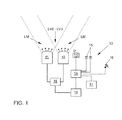
- FIG. 1 is schematically illustrated the structure of a headlamp system 10 for a vehicle according to an embodiment of the invention.
- a headlamp system 10 is particularly suitable for all road vehicles.
- the headlight system 10 shown comprises two headlights 11, 12 and is intended for use in a passenger car or truck.
- the headlamp system may comprise several or even only one headlamp, the latter, for example, for use in a two-wheeler.
- the light emission of the headlights 11, 12 is controllable by a control unit 19 according to a calculated light pattern LM.
- the headlights 11, 12 each include, for example, a plurality of light sources which can emit light in certain solid angle regions and can be controlled separately in their light intensity.
- the headlights 11, 12 include, for example, a plurality of LEDs (Light Emitting Diode), whose power supply is individually adjustable.
- LEDs have the advantage that the light emitted by them can be adjusted virtually continuously and without appreciable time delay.
- the light pattern LM to be emitted can thus not only be quickly adapted to the requirements, but it is also possible to generate repetitive light patterns LM without technical difficulties.
- LEDs are not only energy saving in operation, but it can even be saved by the stepless control with reduced light emission even more energy.
- the headlamps 11, 12 comprise, alternatively or additionally, in each case a halogen lamp, for example a xenon lamp, whose light emission can be changed in each case by one or more electromechanically adjustable diaphragm (s).
- the halogen lamps can furthermore be horizontally and / or vertically pivotable so that an adaptation of the light pattern LM to be emitted can also be achieved.
- a camera module 13 installed in the vehicle takes time-resolved image data from the environment, in particular in the forward stretch of the vehicle.
- the time-resolved image data are suitable for determining therefrom the light distribution LV0-LV3 in the surroundings of the vehicle and for detecting information relating to the traffic situation in the surroundings of the vehicle.
- CMOS Complementary Metal Oxide Semiconductor
- the light distribution LV0 - LV3 usually changes continuously. This is because, on the one hand, the vehicle moves away, as a result of which the reflection behavior in the preceding route section possibly changes.
- the instantaneous light distribution LV0-LV3 is also influenced by temporally changing extraneous light sources.
- Light distributions LV0 relate to arbitrary light distributions
- light distributions LV1 - LV3 are light distributions adapted to a corresponding situation within the meaning of the invention.
- the adapted light distributions LV1-LV3 are, however, changed in the course of time to an arbitrary light distribution LV0 and have to be readjusted by a light pattern LM which has in turn been changed.
- the image data is analyzed for information regarding the traffic situation in the vicinity of the vehicle.
- information is extracted from the image data, which provides information on the presence of other road users, in particular pedestrians and cyclists, but also on the existence of objects or e.g. Animals on or at the edge of the roadway.
- the differential analysis of the time-resolved image data also movements of such road users or objects can be determined.
- the respective traffic situation is assigned to a criticality class. If no particular traffic hazard is derived from the information, e.g. if the road and the roadside are free, the traffic situation is assigned a low criticality class. On the other hand, if persons or objects are detected whose direction of movement points into the driving trajectory of their own vehicle, a high criticality level is assigned.
- the traffic situation detection device 14 accesses a series of further information and data. It captures further information about the traffic situation via environment sensors 15, by means of which, for example, obstacles in the road environment can be detected. Over a Radio interface 16 information from other vehicles (so-called car-to-car communication), traffic facilities, such as traffic lights, or traffic services can be received. Further information, eg route information of the route section ahead or congestion information, is received by a connected navigation system 17.
- the analysis result of the traffic situation detection device 14, in particular the criticality class of the respective traffic situation, is transmitted to the arithmetic unit 18.
- the image data of the camera module 13 with respect to the light distribution LV0 are evaluated, and taking into account the criticality class, a new light distribution LV1 - LV3 to be achieved is determined. From inhomogeneities in the detected light distribution LV0 can be inferred to extraneous light sources and reflections.
- the light distribution LV1 - LV3 to be achieved thereby simulates the surroundings of the vehicle as perceived individually by the driver in the respective situation.
- the light-dark adaptation of the driver's eyes is taken into account and compensated accordingly by the light distribution LV1-LV3 to be achieved.
- the temporal change in the brightness of the point which the driver is currently focusing on, or a glance of the driver from a first viewing direction in a second, differently bright-looking viewing direction is detected.
- the light pattern LM From the light distribution LV1-LV3 to be achieved with respect to the detected light distribution LV0, data for the light pattern LM to be newly emitted for illuminating the surroundings of the vehicle is calculated as a function of the detected light distribution LV0. Furthermore, even if the criticality class changes, the light pattern LM must be adapted if a light pattern LV1-LV3 adapted so far is to be replaced by another light pattern LV1-LV3 to be achieved.
- the control unit 19 receives the data relating to the light pattern LM to be emitted from the arithmetic unit 18 and converts these into the associated control commands for controlling the headlights 11, 12.
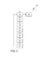
- FIG. 2 a flow chart 20 of the method for controlling the light emission of the headlamp system 10 according to an embodiment of the invention is shown.
- the method is initialized in a step 21 by detecting the switching on of the light function provided by the method according to the invention.
- the light function can be activated automatically when turning on the headlights 11, 12. It can also be separately activated or switched off after the headlights 11, 12 have been turned on.
- step 22 the light distribution LV0 is detected in the surroundings of the vehicle, in particular in the preceding route section, which is illuminated by the headlights 11, 12 or, in principle, can be illuminated by the headlights 11, 12.
- the image data captured by the camera module 13 are evaluated.
- step 23 information about the current traffic situation in the vicinity of the own vehicle is detected.
- the image data of the camera module 13, the data of the environment sensors 15 and a number of other available information are merged.
- messages from other road users and communications from traffic infrastructure facilities are detected, e.g. Notifications of traffic lights or traffic guidance systems.
- the entirety of the available information is assembled into an overall traffic image and assigned to one of several predefined traffic standard situations.
- the traffic situation is assigned to a criticality class.
- the criticality classes can be escalation levels of rising accident risk. However, it is also possible to predefine several criticality classes with a similar or identical accident risk. A possible classification of the criticality classes is in connection with the FIG. 5 discussed.
- Each criticality class is assigned a target light distribution, by means of which the driver of the vehicle should be prepared as well as possible for the existing traffic situation.
- a target light distribution is specified in particular generically and still needs to be adapted to the specific situation.
- it is parameterized, ie it must take into account the specific parameters of the traffic situation in the vicinity of the vehicle, eg distance, size and type of obstacle on the road.
- the detected light distribution LV0 and the determined criticality class the light distribution LV1 - LV3 to be achieved is calculated in a step 25.
- the light distribution LV1 - LV3 to be reached should support the driver in that This can see as relaxed as possible and, if necessary, attention is drawn to danger areas.
- step 26 the light pattern LM to be emitted by the headlights 11, 12 for illuminating the surroundings of the vehicle is calculated from the light distribution LV1-LV3 to be achieved. From the light distribution LV1 - LV3 to be reached, the control signals for controlling the headlights 11, 12 are thus derived, taking into account the reflections and extraneous light sources.
- step 27 the headlights 11, 12 are finally controlled in accordance with the calculated light pattern LM. It is, for example, depending on the design of the headlights 11, 12 changed the position of the aperture and / or individual LEDs that emit light in a certain range, turned on, off, dimmed or otherwise changed in their light emission, depending on how the momentary emitting light pattern LM is to be adapted.
- the method is continued continuously because a dynamic adaptation of the light emission of the headlights 11, 12 is necessary due to the driving of the vehicle, extraneous light sources and changes in the traffic situation. It is first checked in step 21, if the headlights 11, 12 are still turned on or the light function is still active. If this is the case, the steps 22 - 27 are repeated, if necessary, the headlights 11, 12 are readjusted, otherwise the process is terminated in step 28.
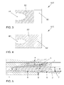
- FIG. 3 a section of an initial light distribution LV0 is shown.
- the light distribution LV0 has, from the driver's point of view, a region B1 with greatly increased light intensity, which results from the reflection of the own headlights 11, 12 on the road and possibly by the glare of an extraneous light source, for example from an oncoming vehicle.
- the surrounding area B2 is much worse illuminated and appears darker.
- the right edge also appears very bright, because from here a lot of light of the own headlights 11, 12 is reflected back from a traffic sign to the driver.
- FIG. 4 is shown how the light distribution LV0 of FIG. 3 an adaptation of the light pattern LM emitted by the headlamps 11, 12 results in a homogenized light distribution LV0 '.
- the light emission which is directed in the direction of the brighter areas B1, B3, is reduced, so that the brightness contrast between the areas B1 ', B3' on the one hand and the area B2 'on the other hand is largely compensated.
- This can be achieved, in particular, if LEDs 11, 12 use LEDs whose light emission is proportional to the energy supplied.
- the reduction of the light emission of individual LEDs thus advantageously leads to energy savings.
- Such a light distribution LV0 ' is particularly useful if the existing traffic situation previously assigned a low criticality class.
- the vehicle is located, for example, in light traffic on a clear highway or highway, without potential traffic obstructions were detected.
- the homogenized light distribution LV0 ' is generally suitable as a basic light distribution, which can be superimposed by a situation-dependent additional light distribution required.
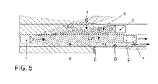
- FIG. 5 Several traffic situations are shown, for which, according to an embodiment of the invention, the light pattern LM to be emitted has been adapted. Shown is the own motor vehicle 1, a preceding vehicle 2 and an oncoming vehicle 3. Furthermore, fictitious positions of pedestrians 4 - 6, a cyclist 7 and an object 9 are shown on the right side of the road. For the pedestrians 4, 5 a movement was detected, which indicates the crossing of the roadway. Right next to the roadway is a highly reflective road sign. 8
- the traffic situations are assigned to at least four different criticality classes in this embodiment.
- a low criticality class ZERO applies to all traffic situations in which no increased traffic danger has been detected. In this case, preceding vehicles 2 or oncoming vehicles 3 may have been detected. As long as the distance to the vehicle in front 2 does not fall below a critical limit value and the driving trajectory of these vehicles 2, 3 run "normally", i. In particular, according to the prescribed lanes, it is assumed that there is no increased traffic danger.
- the adaptation of the light pattern LM is limited in this case to a homogenization of the light distribution LV0 '.
- Criticality classes I-1, I-2 and I-3 are assigned to which high criticality classes I-1, I-2 and I-3 are assigned.
- an adaptation of the light pattern LM to achieve a light distribution LV1-LV3 is provided for these cases.
- Criticality classes I-1 to I-3 are not necessarily to be understood as escalation levels. They only reflect one specific hazard profile whose associated hazards are to be reduced by the one specific light distribution LV1 - LV3.
- the light distributions LV1 - LV3 are generated by superimposing the light distributions LV0 'with a corresponding additional light distribution.
- the causes can be a dazzling extraneous light source, strong reflections or strongly absorbing, ie poorly visible objects, eg the object 9.
- the light pattern LM to be emitted is in a forwardly oriented angular range increases spatially limited, whereby the light intensity is selectively raised on the own roadway and the light distribution LV1 is generated.
- the criticality level I-2 it was recorded that the pedestrian 5 is on the lane of oncoming traffic and is moving in the direction of its own lane.
- the light pattern LM to be emitted is then increased in an angle range in the direction of the pedestrian 5, whereby the light intensity in the danger area is selectively raised and the light distribution LV2 is generated.
- the angular range of the light output with increased light intensity is horizontally and vertically hard limited, e.g. vertically at hip height.
- the driver of the vehicle 1 not only keeps the danger source in view, but the pedestrian 5 and the driver of the oncoming vehicle 3 are also warned by the "light spot".
- the light pattern LM to be emitted is changed in a time-pulsating or flashing manner, in particular in the case of such an acute traffic hazard.
- the light spot is e.g. modulated with an increasing flashing frequency of 2Hz to 5Hz, whereby the pedestrian 5 and the driver of the oncoming vehicle 3 are even better warned.
- the existence of potential sources of danger was recorded in otherwise free lanes at the edge of the road. It was e.g. on the right side of the road a pedestrian 6, a cyclist 7 and an object 9 and on the left roadside a pedestrian 4 detected.
- the light pattern LM to be emitted is extended into the lateral angular ranges, whereby the light intensity at the roadside is selectively raised and the light distribution LV3 is generated. As described above with reference to the light distribution LV2, glare of the other road users is thereby avoided.
- a multiplicity of traffic situations can be classified and a correspondingly large number of criticality classes and associated target light distributions predefined.
- the measures mentioned can also be combined as desired. This applies both to the use of specific headlamps for emitting specific light patterns LM, which may comprise any combination of incandescent lamps, halogen lamps and LEDs, as well as for the characteristics of the light distributions, the homogenization, spatially selective increase in light intensity and temporal change by, for example, flashing can.
Landscapes
- Engineering & Computer Science (AREA)
- Mechanical Engineering (AREA)
- Lighting Device Outwards From Vehicle And Optical Signal (AREA)
Applications Claiming Priority (1)
| Application Number | Priority Date | Filing Date | Title |
|---|---|---|---|
| DE102012016782.2A DE102012016782B4 (de) | 2012-08-23 | 2012-08-23 | Verfahren zum Betreiben eines Scheinwerfersystems und Scheinwerfersystem für ein Fahrzeug |
Publications (3)
| Publication Number | Publication Date |
|---|---|
| EP2700536A2 true EP2700536A2 (fr) | 2014-02-26 |
| EP2700536A3 EP2700536A3 (fr) | 2018-04-25 |
| EP2700536B1 EP2700536B1 (fr) | 2024-05-22 |
Family
ID=48985613
Family Applications (1)
| Application Number | Title | Priority Date | Filing Date |
|---|---|---|---|
| EP13180226.6A Active EP2700536B1 (fr) | 2012-08-23 | 2013-08-13 | Procédé de contrôle d'un système de phare et système de phare pour un véhicule |
Country Status (2)
| Country | Link |
|---|---|
| EP (1) | EP2700536B1 (fr) |
| DE (1) | DE102012016782B4 (fr) |
Cited By (10)
| Publication number | Priority date | Publication date | Assignee | Title |
|---|---|---|---|---|
| WO2015006793A1 (fr) * | 2013-07-16 | 2015-01-22 | Zizala Lichtsysteme Gmbh | Éclairage dynamique d'un champ de vision |
| US20170203682A1 (en) * | 2016-01-19 | 2017-07-20 | Harman International Industries, Inc. | Techniques for optimizing vehicle headlights based on situational awareness |
| CN109299557A (zh) * | 2018-10-08 | 2019-02-01 | 马瑞利汽车零部件(芜湖)有限公司 | 一种adb前照灯系统的调光设计方法 |
| US10442341B2 (en) | 2014-12-22 | 2019-10-15 | GM Global Technology Operations LLC | Motor vehicle headlamp system, motor vehicle, method for operating a motor vehicle headlamp system as well as computer program product |
| CN111837023A (zh) * | 2018-03-22 | 2020-10-27 | 奥迪股份公司 | 用于调整机动车的阵列式前照灯的位置的方法、控制装置和机动车 |
| EP3932739A1 (fr) * | 2020-07-01 | 2022-01-05 | Mazda Motor Corporation | Système de commande de phare |
| CN114076284A (zh) * | 2020-08-20 | 2022-02-22 | 大众汽车股份公司 | 具有对光分布中不均匀性的补偿的车辆前灯 |
| FR3119009A1 (fr) * | 2021-01-21 | 2022-07-22 | Psa Automobiles Sa | Procédé de commande d’un projecteur de véhicule automobile |
| CN119527162A (zh) * | 2025-01-21 | 2025-02-28 | 深圳市太阳鑫源科技有限公司 | 一种基于环境适配的自适应led车灯控制策略优化方法 |
| CN120552727A (zh) * | 2025-07-30 | 2025-08-29 | 吉林大学 | 一种前照灯灯光自适应主动调节方法 |
Families Citing this family (5)
| Publication number | Priority date | Publication date | Assignee | Title |
|---|---|---|---|---|
| DE102014019344A1 (de) * | 2014-12-22 | 2016-06-23 | GM Global Technology Operations LLC (n. d. Ges. d. Staates Delaware) | Kraftfahrzeugscheinwerfer, Kraftfahrzeugscheinwerfersystem, Kraftfahrzeug sowie Verfahren zum Betrieb eines Kraftfahrzeugs |
| DE102016004208A1 (de) * | 2016-04-06 | 2017-10-12 | Daimler Ag | Verfahren und Vorrichtung zur Ausleuchtung einer Fahrzeugumgebung |
| DE102018129280A1 (de) * | 2018-11-21 | 2020-05-28 | HELLA GmbH & Co. KGaA | Steuergerät zum Steuern von Matrix- Scheinwerfern |
| DE102021206735A1 (de) | 2021-06-29 | 2022-12-29 | Psa Automobiles Sa | Scheinwerfermodul eines Fahrzeugscheinwerfers, Fahrzeugscheinwerfer und den Fahrzeugscheinwerfer aufweisendes Fahrzeug |
| DE102022126939A1 (de) | 2022-10-14 | 2024-04-25 | Audi Aktiengesellschaft | Verfahren zur Beleuchtung einer Umgebung eines Kraftfahrzeugs und eines Zusatzfahrzeugs, Kraftfahrzeug |
Citations (2)
| Publication number | Priority date | Publication date | Assignee | Title |
|---|---|---|---|---|
| DE102007009895A1 (de) | 2006-03-02 | 2007-10-18 | Denso Corp., Kariya | Steuergerät zur Steuerung einer Fahrzeugeinheit |
| DE102009040006A1 (de) | 2009-09-03 | 2011-03-10 | Dr. Ing. H.C. F. Porsche Aktiengesellschaft | Scheinwerferanordnung für Fahrzeuge und Verfahren zum Betreiben einer Scheinwerferanordnung für Fahrzeuge |
Family Cites Families (6)
| Publication number | Priority date | Publication date | Assignee | Title |
|---|---|---|---|---|
| DE10354104A1 (de) | 2003-11-19 | 2005-06-02 | Bayerische Motoren Werke Ag | Verfahren zur Steuerung der Ausleuchtung eines seitlichen Fahrbahnbereichs mittels eines Hilfsscheinwerfers für ein Fahrzeug |
| US7914187B2 (en) | 2007-07-12 | 2011-03-29 | Magna Electronics Inc. | Automatic lighting system with adaptive alignment function |
| DE102008025947A1 (de) | 2008-05-30 | 2009-12-03 | Hella Kgaa Hueck & Co. | Verfahren und Vorrichtung zum Steuern der Lichtabgabe eines Frontscheinwerfers eines Fahrzeugs |
| DE102008058386A1 (de) * | 2008-11-21 | 2010-05-27 | Daimler Ag | Verfahren und Anordnung zur Ansteuerung eines Fahrzeugscheinwerfers |
| DE102009037559A1 (de) * | 2009-08-13 | 2011-02-17 | Automotive Lighting Reutlingen Gmbh | Frontscheinwerfer mit einem LED-Teilfernlichtmodul |
| DE102012002226A1 (de) * | 2012-02-04 | 2012-08-30 | Daimler Ag | Verfahren zur Steuerung einer Fahrlichtverteilung für ein Fahrzeug |
-
2012
- 2012-08-23 DE DE102012016782.2A patent/DE102012016782B4/de active Active
-
2013
- 2013-08-13 EP EP13180226.6A patent/EP2700536B1/fr active Active
Patent Citations (2)
| Publication number | Priority date | Publication date | Assignee | Title |
|---|---|---|---|---|
| DE102007009895A1 (de) | 2006-03-02 | 2007-10-18 | Denso Corp., Kariya | Steuergerät zur Steuerung einer Fahrzeugeinheit |
| DE102009040006A1 (de) | 2009-09-03 | 2011-03-10 | Dr. Ing. H.C. F. Porsche Aktiengesellschaft | Scheinwerferanordnung für Fahrzeuge und Verfahren zum Betreiben einer Scheinwerferanordnung für Fahrzeuge |
Cited By (13)
| Publication number | Priority date | Publication date | Assignee | Title |
|---|---|---|---|---|
| WO2015006793A1 (fr) * | 2013-07-16 | 2015-01-22 | Zizala Lichtsysteme Gmbh | Éclairage dynamique d'un champ de vision |
| US9981593B2 (en) | 2013-07-16 | 2018-05-29 | Zkw Group Gmbh | Dynamic means of illuminating a field of vision |
| US10442341B2 (en) | 2014-12-22 | 2019-10-15 | GM Global Technology Operations LLC | Motor vehicle headlamp system, motor vehicle, method for operating a motor vehicle headlamp system as well as computer program product |
| US20170203682A1 (en) * | 2016-01-19 | 2017-07-20 | Harman International Industries, Inc. | Techniques for optimizing vehicle headlights based on situational awareness |
| US11807156B2 (en) | 2018-03-22 | 2023-11-07 | Audi Ag | Method for calibrating a position of a matrix headlamp of a motor vehicle, control device, and motor vehicle |
| CN111837023A (zh) * | 2018-03-22 | 2020-10-27 | 奥迪股份公司 | 用于调整机动车的阵列式前照灯的位置的方法、控制装置和机动车 |
| CN109299557B (zh) * | 2018-10-08 | 2023-03-24 | 马瑞利汽车零部件(芜湖)有限公司 | 一种adb前照灯系统的调光设计方法 |
| CN109299557A (zh) * | 2018-10-08 | 2019-02-01 | 马瑞利汽车零部件(芜湖)有限公司 | 一种adb前照灯系统的调光设计方法 |
| EP3932739A1 (fr) * | 2020-07-01 | 2022-01-05 | Mazda Motor Corporation | Système de commande de phare |
| CN114076284A (zh) * | 2020-08-20 | 2022-02-22 | 大众汽车股份公司 | 具有对光分布中不均匀性的补偿的车辆前灯 |
| FR3119009A1 (fr) * | 2021-01-21 | 2022-07-22 | Psa Automobiles Sa | Procédé de commande d’un projecteur de véhicule automobile |
| CN119527162A (zh) * | 2025-01-21 | 2025-02-28 | 深圳市太阳鑫源科技有限公司 | 一种基于环境适配的自适应led车灯控制策略优化方法 |
| CN120552727A (zh) * | 2025-07-30 | 2025-08-29 | 吉林大学 | 一种前照灯灯光自适应主动调节方法 |
Also Published As
| Publication number | Publication date |
|---|---|
| DE102012016782A1 (de) | 2014-02-27 |
| EP2700536B1 (fr) | 2024-05-22 |
| EP2700536A3 (fr) | 2018-04-25 |
| DE102012016782B4 (de) | 2024-07-25 |
Similar Documents
| Publication | Publication Date | Title |
|---|---|---|
| EP2700536B1 (fr) | Procédé de contrôle d'un système de phare et système de phare pour un véhicule | |
| DE102009009472B4 (de) | Verfahren zum Unterstützen eines Fahrers eines Fahrzeugs und Fahrerassistenzsystem für ein Fahrzeug | |
| EP2562039B1 (fr) | Procédé et dispositif destinés à modifier une émission lumineuse, notamment d'un phare d'un véhicule | |
| DE112017006833B4 (de) | Fahrzeugbeleuchtungssystem | |
| EP2864158B1 (fr) | Procédé d'utilisation d'un système de phare dans un véhicule et système de phare associé | |
| DE102011006580B4 (de) | Verfahren und Steuergerät zur wegabhängigen Einstellung der Leuchtweite eines Beleuchtungssystems für ein Fahrzeug | |
| EP3592605B1 (fr) | Véhicule automobile comprenant un module d'éclairage servant à générer un symbole | |
| DE102012200431B4 (de) | Verfahren zur Bestimmung eines Vorliegens einer Kreuzung in einem von einem Fahrzeug befahrenen Straßenverlauf | |
| WO2019201553A1 (fr) | Procédé permettant la communication d'un véhicule à moteur avec un usager de la route et véhicule à moteur pour mettre en oeuvre ledit procédé | |
| DE102016001692A1 (de) | Fahrerassistenzsystem zur Steuerung einer Lichtabstrahlung einer fahrzeugseitigen Scheinwerfereinrichtung | |
| DE102016122043A1 (de) | Scheinwerfer für Kraftfahrzeuge | |
| EP3018007B1 (fr) | Procede de commande d'un systeme de phare pour un vehicule automobile et systeme de phare et vehicule automobile | |
| EP3242815B1 (fr) | Procédé et système d'aide à la conduite pour assister le conducteur d'un véhicule | |
| WO2009062596A1 (fr) | Procédé et dispositif pour commander les feux de route d'un véhicule | |
| DE102014225513A1 (de) | Verfahren und Steuergerät zum Einstellen einer Charakteristik einer Lichtaussendung zumindest eines Scheinwerfers eines Fahrzeugs | |
| WO2018149807A1 (fr) | Commande d'un phare de véhicule automobile | |
| DE102016005458B4 (de) | Betreiben eines Scheinwerfers | |
| DE102013222628A1 (de) | Verfahren und Vorrichtung zum Erfassen einer Fehleinstellung einer lichttechnischen Einrichtung eines Fahrzeugs | |
| EP4263287B1 (fr) | Procédé de réglage d'un système d'éclairage de véhicule lors de la conduite sur un chantier, et véhicule | |
| DE102016004289A1 (de) | Verfahren und Vorrichtung zur Steuerung einer Fahrzeugbeleuchtung und Fahrzeug mit einer solchen Vorrichtung | |
| DE102015213333A1 (de) | Verfahren und Vorrichtung zur automatischen Steuerung von Scheinwerfern eines Kraftfahrzeugs | |
| DE102023002436B4 (de) | Verfahren zum Betreiben eines Fernlichtassistenten und Fahrzeug | |
| DE102017214496B4 (de) | Kraftfahrzeug mit zumindest einem Leuchtmittel | |
| WO2024256093A1 (fr) | Procédé de fonctionnement d'un assistant de feu de route et véhicule |
Legal Events
| Date | Code | Title | Description |
|---|---|---|---|
| PUAI | Public reference made under article 153(3) epc to a published international application that has entered the european phase |
Free format text: ORIGINAL CODE: 0009012 |
|
| AK | Designated contracting states |
Kind code of ref document: A2 Designated state(s): AL AT BE BG CH CY CZ DE DK EE ES FI FR GB GR HR HU IE IS IT LI LT LU LV MC MK MT NL NO PL PT RO RS SE SI SK SM TR |
|
| AX | Request for extension of the european patent |
Extension state: BA ME |
|
| PUAL | Search report despatched |
Free format text: ORIGINAL CODE: 0009013 |
|
| AK | Designated contracting states |
Kind code of ref document: A3 Designated state(s): AL AT BE BG CH CY CZ DE DK EE ES FI FR GB GR HR HU IE IS IT LI LT LU LV MC MK MT NL NO PL PT RO RS SE SI SK SM TR |
|
| AX | Request for extension of the european patent |
Extension state: BA ME |
|
| RIC1 | Information provided on ipc code assigned before grant |
Ipc: B60Q 1/08 20060101AFI20180322BHEP Ipc: G08G 1/16 20060101ALI20180322BHEP |
|
| STAA | Information on the status of an ep patent application or granted ep patent |
Free format text: STATUS: REQUEST FOR EXAMINATION WAS MADE |
|
| 17P | Request for examination filed |
Effective date: 20181025 |
|
| RBV | Designated contracting states (corrected) |
Designated state(s): AL AT BE BG CH CY CZ DE DK EE ES FI FR GB GR HR HU IE IS IT LI LT LU LV MC MK MT NL NO PL PT RO RS SE SI SK SM TR |
|
| STAA | Information on the status of an ep patent application or granted ep patent |
Free format text: STATUS: EXAMINATION IS IN PROGRESS |
|
| 17Q | First examination report despatched |
Effective date: 20200610 |
|
| GRAP | Despatch of communication of intention to grant a patent |
Free format text: ORIGINAL CODE: EPIDOSNIGR1 |
|
| STAA | Information on the status of an ep patent application or granted ep patent |
Free format text: STATUS: GRANT OF PATENT IS INTENDED |
|
| INTG | Intention to grant announced |
Effective date: 20240116 |
|
| GRAS | Grant fee paid |
Free format text: ORIGINAL CODE: EPIDOSNIGR3 |
|
| GRAA | (expected) grant |
Free format text: ORIGINAL CODE: 0009210 |
|
| STAA | Information on the status of an ep patent application or granted ep patent |
Free format text: STATUS: THE PATENT HAS BEEN GRANTED |
|
| P01 | Opt-out of the competence of the unified patent court (upc) registered |
Effective date: 20240408 |
|
| AK | Designated contracting states |
Kind code of ref document: B1 Designated state(s): AL AT BE BG CH CY CZ DE DK EE ES FI FR GB GR HR HU IE IS IT LI LT LU LV MC MK MT NL NO PL PT RO RS SE SI SK SM TR |
|
| REG | Reference to a national code |
Ref country code: GB Ref legal event code: FG4D Free format text: NOT ENGLISH |
|
| REG | Reference to a national code |
Ref country code: CH Ref legal event code: EP |
|
| REG | Reference to a national code |
Ref country code: DE Ref legal event code: R096 Ref document number: 502013016522 Country of ref document: DE |
|
| REG | Reference to a national code |
Ref country code: IE Ref legal event code: FG4D Free format text: LANGUAGE OF EP DOCUMENT: GERMAN |
|
| REG | Reference to a national code |
Ref country code: LT Ref legal event code: MG9D |
|
| REG | Reference to a national code |
Ref country code: NL Ref legal event code: MP Effective date: 20240522 |
|
| PG25 | Lapsed in a contracting state [announced via postgrant information from national office to epo] |
Ref country code: IS Free format text: LAPSE BECAUSE OF FAILURE TO SUBMIT A TRANSLATION OF THE DESCRIPTION OR TO PAY THE FEE WITHIN THE PRESCRIBED TIME-LIMIT Effective date: 20240922 |
|
| PG25 | Lapsed in a contracting state [announced via postgrant information from national office to epo] |
Ref country code: BG Free format text: LAPSE BECAUSE OF FAILURE TO SUBMIT A TRANSLATION OF THE DESCRIPTION OR TO PAY THE FEE WITHIN THE PRESCRIBED TIME-LIMIT Effective date: 20240522 |
|
| PG25 | Lapsed in a contracting state [announced via postgrant information from national office to epo] |
Ref country code: HR Free format text: LAPSE BECAUSE OF FAILURE TO SUBMIT A TRANSLATION OF THE DESCRIPTION OR TO PAY THE FEE WITHIN THE PRESCRIBED TIME-LIMIT Effective date: 20240522 Ref country code: FI Free format text: LAPSE BECAUSE OF FAILURE TO SUBMIT A TRANSLATION OF THE DESCRIPTION OR TO PAY THE FEE WITHIN THE PRESCRIBED TIME-LIMIT Effective date: 20240522 |
|
| PG25 | Lapsed in a contracting state [announced via postgrant information from national office to epo] |
Ref country code: GR Free format text: LAPSE BECAUSE OF FAILURE TO SUBMIT A TRANSLATION OF THE DESCRIPTION OR TO PAY THE FEE WITHIN THE PRESCRIBED TIME-LIMIT Effective date: 20240823 |
|
| PG25 | Lapsed in a contracting state [announced via postgrant information from national office to epo] |
Ref country code: PT Free format text: LAPSE BECAUSE OF FAILURE TO SUBMIT A TRANSLATION OF THE DESCRIPTION OR TO PAY THE FEE WITHIN THE PRESCRIBED TIME-LIMIT Effective date: 20240923 |
|
| PG25 | Lapsed in a contracting state [announced via postgrant information from national office to epo] |
Ref country code: NL Free format text: LAPSE BECAUSE OF FAILURE TO SUBMIT A TRANSLATION OF THE DESCRIPTION OR TO PAY THE FEE WITHIN THE PRESCRIBED TIME-LIMIT Effective date: 20240522 |
|
| PG25 | Lapsed in a contracting state [announced via postgrant information from national office to epo] |
Ref country code: ES Free format text: LAPSE BECAUSE OF FAILURE TO SUBMIT A TRANSLATION OF THE DESCRIPTION OR TO PAY THE FEE WITHIN THE PRESCRIBED TIME-LIMIT Effective date: 20240522 |
|
| PG25 | Lapsed in a contracting state [announced via postgrant information from national office to epo] |
Ref country code: PL Free format text: LAPSE BECAUSE OF FAILURE TO SUBMIT A TRANSLATION OF THE DESCRIPTION OR TO PAY THE FEE WITHIN THE PRESCRIBED TIME-LIMIT Effective date: 20240522 |
|
| PG25 | Lapsed in a contracting state [announced via postgrant information from national office to epo] |
Ref country code: LV Free format text: LAPSE BECAUSE OF FAILURE TO SUBMIT A TRANSLATION OF THE DESCRIPTION OR TO PAY THE FEE WITHIN THE PRESCRIBED TIME-LIMIT Effective date: 20240522 |
|
| PG25 | Lapsed in a contracting state [announced via postgrant information from national office to epo] |
Ref country code: PT Free format text: LAPSE BECAUSE OF FAILURE TO SUBMIT A TRANSLATION OF THE DESCRIPTION OR TO PAY THE FEE WITHIN THE PRESCRIBED TIME-LIMIT Effective date: 20240923 Ref country code: PL Free format text: LAPSE BECAUSE OF FAILURE TO SUBMIT A TRANSLATION OF THE DESCRIPTION OR TO PAY THE FEE WITHIN THE PRESCRIBED TIME-LIMIT Effective date: 20240522 Ref country code: NO Free format text: LAPSE BECAUSE OF FAILURE TO SUBMIT A TRANSLATION OF THE DESCRIPTION OR TO PAY THE FEE WITHIN THE PRESCRIBED TIME-LIMIT Effective date: 20240822 Ref country code: NL Free format text: LAPSE BECAUSE OF FAILURE TO SUBMIT A TRANSLATION OF THE DESCRIPTION OR TO PAY THE FEE WITHIN THE PRESCRIBED TIME-LIMIT Effective date: 20240522 Ref country code: LV Free format text: LAPSE BECAUSE OF FAILURE TO SUBMIT A TRANSLATION OF THE DESCRIPTION OR TO PAY THE FEE WITHIN THE PRESCRIBED TIME-LIMIT Effective date: 20240522 Ref country code: IS Free format text: LAPSE BECAUSE OF FAILURE TO SUBMIT A TRANSLATION OF THE DESCRIPTION OR TO PAY THE FEE WITHIN THE PRESCRIBED TIME-LIMIT Effective date: 20240922 Ref country code: HR Free format text: LAPSE BECAUSE OF FAILURE TO SUBMIT A TRANSLATION OF THE DESCRIPTION OR TO PAY THE FEE WITHIN THE PRESCRIBED TIME-LIMIT Effective date: 20240522 Ref country code: GR Free format text: LAPSE BECAUSE OF FAILURE TO SUBMIT A TRANSLATION OF THE DESCRIPTION OR TO PAY THE FEE WITHIN THE PRESCRIBED TIME-LIMIT Effective date: 20240823 Ref country code: FI Free format text: LAPSE BECAUSE OF FAILURE TO SUBMIT A TRANSLATION OF THE DESCRIPTION OR TO PAY THE FEE WITHIN THE PRESCRIBED TIME-LIMIT Effective date: 20240522 Ref country code: ES Free format text: LAPSE BECAUSE OF FAILURE TO SUBMIT A TRANSLATION OF THE DESCRIPTION OR TO PAY THE FEE WITHIN THE PRESCRIBED TIME-LIMIT Effective date: 20240522 Ref country code: BG Free format text: LAPSE BECAUSE OF FAILURE TO SUBMIT A TRANSLATION OF THE DESCRIPTION OR TO PAY THE FEE WITHIN THE PRESCRIBED TIME-LIMIT Effective date: 20240522 Ref country code: RS Free format text: LAPSE BECAUSE OF FAILURE TO SUBMIT A TRANSLATION OF THE DESCRIPTION OR TO PAY THE FEE WITHIN THE PRESCRIBED TIME-LIMIT Effective date: 20240822 |
|
| PG25 | Lapsed in a contracting state [announced via postgrant information from national office to epo] |
Ref country code: DK Free format text: LAPSE BECAUSE OF FAILURE TO SUBMIT A TRANSLATION OF THE DESCRIPTION OR TO PAY THE FEE WITHIN THE PRESCRIBED TIME-LIMIT Effective date: 20240522 |
|
| PG25 | Lapsed in a contracting state [announced via postgrant information from national office to epo] |
Ref country code: EE Free format text: LAPSE BECAUSE OF FAILURE TO SUBMIT A TRANSLATION OF THE DESCRIPTION OR TO PAY THE FEE WITHIN THE PRESCRIBED TIME-LIMIT Effective date: 20240522 |
|
| PG25 | Lapsed in a contracting state [announced via postgrant information from national office to epo] |
Ref country code: CZ Free format text: LAPSE BECAUSE OF FAILURE TO SUBMIT A TRANSLATION OF THE DESCRIPTION OR TO PAY THE FEE WITHIN THE PRESCRIBED TIME-LIMIT Effective date: 20240522 |
|
| PG25 | Lapsed in a contracting state [announced via postgrant information from national office to epo] |
Ref country code: RO Free format text: LAPSE BECAUSE OF FAILURE TO SUBMIT A TRANSLATION OF THE DESCRIPTION OR TO PAY THE FEE WITHIN THE PRESCRIBED TIME-LIMIT Effective date: 20240522 Ref country code: SK Free format text: LAPSE BECAUSE OF FAILURE TO SUBMIT A TRANSLATION OF THE DESCRIPTION OR TO PAY THE FEE WITHIN THE PRESCRIBED TIME-LIMIT Effective date: 20240522 |
|
| PG25 | Lapsed in a contracting state [announced via postgrant information from national office to epo] |
Ref country code: SM Free format text: LAPSE BECAUSE OF FAILURE TO SUBMIT A TRANSLATION OF THE DESCRIPTION OR TO PAY THE FEE WITHIN THE PRESCRIBED TIME-LIMIT Effective date: 20240522 |
|
| PG25 | Lapsed in a contracting state [announced via postgrant information from national office to epo] |
Ref country code: SM Free format text: LAPSE BECAUSE OF FAILURE TO SUBMIT A TRANSLATION OF THE DESCRIPTION OR TO PAY THE FEE WITHIN THE PRESCRIBED TIME-LIMIT Effective date: 20240522 Ref country code: SK Free format text: LAPSE BECAUSE OF FAILURE TO SUBMIT A TRANSLATION OF THE DESCRIPTION OR TO PAY THE FEE WITHIN THE PRESCRIBED TIME-LIMIT Effective date: 20240522 Ref country code: RO Free format text: LAPSE BECAUSE OF FAILURE TO SUBMIT A TRANSLATION OF THE DESCRIPTION OR TO PAY THE FEE WITHIN THE PRESCRIBED TIME-LIMIT Effective date: 20240522 Ref country code: EE Free format text: LAPSE BECAUSE OF FAILURE TO SUBMIT A TRANSLATION OF THE DESCRIPTION OR TO PAY THE FEE WITHIN THE PRESCRIBED TIME-LIMIT Effective date: 20240522 Ref country code: DK Free format text: LAPSE BECAUSE OF FAILURE TO SUBMIT A TRANSLATION OF THE DESCRIPTION OR TO PAY THE FEE WITHIN THE PRESCRIBED TIME-LIMIT Effective date: 20240522 Ref country code: CZ Free format text: LAPSE BECAUSE OF FAILURE TO SUBMIT A TRANSLATION OF THE DESCRIPTION OR TO PAY THE FEE WITHIN THE PRESCRIBED TIME-LIMIT Effective date: 20240522 |
|
| PG25 | Lapsed in a contracting state [announced via postgrant information from national office to epo] |
Ref country code: IT Free format text: LAPSE BECAUSE OF FAILURE TO SUBMIT A TRANSLATION OF THE DESCRIPTION OR TO PAY THE FEE WITHIN THE PRESCRIBED TIME-LIMIT Effective date: 20240522 |
|
| REG | Reference to a national code |
Ref country code: DE Ref legal event code: R097 Ref document number: 502013016522 Country of ref document: DE |
|
| PLBE | No opposition filed within time limit |
Free format text: ORIGINAL CODE: 0009261 |
|
| STAA | Information on the status of an ep patent application or granted ep patent |
Free format text: STATUS: NO OPPOSITION FILED WITHIN TIME LIMIT |
|
| REG | Reference to a national code |
Ref country code: CH Ref legal event code: PL |
|
| PG25 | Lapsed in a contracting state [announced via postgrant information from national office to epo] |
Ref country code: LU Free format text: LAPSE BECAUSE OF NON-PAYMENT OF DUE FEES Effective date: 20240813 |
|
| PG25 | Lapsed in a contracting state [announced via postgrant information from national office to epo] |
Ref country code: CH Free format text: LAPSE BECAUSE OF NON-PAYMENT OF DUE FEES Effective date: 20240831 Ref country code: MC Free format text: LAPSE BECAUSE OF FAILURE TO SUBMIT A TRANSLATION OF THE DESCRIPTION OR TO PAY THE FEE WITHIN THE PRESCRIBED TIME-LIMIT Effective date: 20240522 Ref country code: SI Free format text: LAPSE BECAUSE OF FAILURE TO SUBMIT A TRANSLATION OF THE DESCRIPTION OR TO PAY THE FEE WITHIN THE PRESCRIBED TIME-LIMIT Effective date: 20240522 |
|
| 26N | No opposition filed |
Effective date: 20250225 |
|
| REG | Reference to a national code |
Ref country code: BE Ref legal event code: MM Effective date: 20240831 |
|
| PG25 | Lapsed in a contracting state [announced via postgrant information from national office to epo] |
Ref country code: BE Free format text: LAPSE BECAUSE OF NON-PAYMENT OF DUE FEES Effective date: 20240831 |
|
| PG25 | Lapsed in a contracting state [announced via postgrant information from national office to epo] |
Ref country code: IE Free format text: LAPSE BECAUSE OF NON-PAYMENT OF DUE FEES Effective date: 20240813 |
|
| PG25 | Lapsed in a contracting state [announced via postgrant information from national office to epo] |
Ref country code: SE Free format text: LAPSE BECAUSE OF FAILURE TO SUBMIT A TRANSLATION OF THE DESCRIPTION OR TO PAY THE FEE WITHIN THE PRESCRIBED TIME-LIMIT Effective date: 20240522 |
|
| PGFP | Annual fee paid to national office [announced via postgrant information from national office to epo] |
Ref country code: DE Payment date: 20250831 Year of fee payment: 13 |
|
| REG | Reference to a national code |
Ref country code: AT Ref legal event code: MM01 Ref document number: 1688522 Country of ref document: AT Kind code of ref document: T Effective date: 20240813 |
|
| PGFP | Annual fee paid to national office [announced via postgrant information from national office to epo] |
Ref country code: GB Payment date: 20250826 Year of fee payment: 13 |
|
| PG25 | Lapsed in a contracting state [announced via postgrant information from national office to epo] |
Ref country code: AT Free format text: LAPSE BECAUSE OF NON-PAYMENT OF DUE FEES Effective date: 20240813 |
|
| PGFP | Annual fee paid to national office [announced via postgrant information from national office to epo] |
Ref country code: FR Payment date: 20250825 Year of fee payment: 13 |
|
| PG25 | Lapsed in a contracting state [announced via postgrant information from national office to epo] |
Ref country code: CY Free format text: LAPSE BECAUSE OF FAILURE TO SUBMIT A TRANSLATION OF THE DESCRIPTION OR TO PAY THE FEE WITHIN THE PRESCRIBED TIME-LIMIT; INVALID AB INITIO Effective date: 20130813 |
|
| PG25 | Lapsed in a contracting state [announced via postgrant information from national office to epo] |
Ref country code: HU Free format text: LAPSE BECAUSE OF FAILURE TO SUBMIT A TRANSLATION OF THE DESCRIPTION OR TO PAY THE FEE WITHIN THE PRESCRIBED TIME-LIMIT; INVALID AB INITIO Effective date: 20130813 |