EP2700577B1 - Cartouche pour dispositif de cerclage - Google Patents
Cartouche pour dispositif de cerclage Download PDFInfo
- Publication number
- EP2700577B1 EP2700577B1 EP13003941.5A EP13003941A EP2700577B1 EP 2700577 B1 EP2700577 B1 EP 2700577B1 EP 13003941 A EP13003941 A EP 13003941A EP 2700577 B1 EP2700577 B1 EP 2700577B1
- Authority
- EP
- European Patent Office
- Prior art keywords
- magazine
- protection means
- edge
- removal tool
- conveying
- Prior art date
- Legal status (The legal status is an assumption and is not a legal conclusion. Google has not performed a legal analysis and makes no representation as to the accuracy of the status listed.)
- Active
Links
Images


Classifications
-
- B—PERFORMING OPERATIONS; TRANSPORTING
- B65—CONVEYING; PACKING; STORING; HANDLING THIN OR FILAMENTARY MATERIAL
- B65H—HANDLING THIN OR FILAMENTARY MATERIAL, e.g. SHEETS, WEBS, CABLES
- B65H5/00—Feeding articles separated from piles; Feeding articles to machines
- B65H5/02—Feeding articles separated from piles; Feeding articles to machines by belts or chains, e.g. between belts or chains
- B65H5/021—Feeding articles separated from piles; Feeding articles to machines by belts or chains, e.g. between belts or chains by belts
-
- B—PERFORMING OPERATIONS; TRANSPORTING
- B65—CONVEYING; PACKING; STORING; HANDLING THIN OR FILAMENTARY MATERIAL
- B65B—MACHINES, APPARATUS OR DEVICES FOR, OR METHODS OF, PACKAGING ARTICLES OR MATERIALS; UNPACKING
- B65B13/00—Bundling articles
- B65B13/18—Details of, or auxiliary devices used in, bundling machines or bundling tools
- B65B13/181—Details of, or auxiliary devices used in, bundling machines or bundling tools applying edge protecting members during bundling
-
- B—PERFORMING OPERATIONS; TRANSPORTING
- B65—CONVEYING; PACKING; STORING; HANDLING THIN OR FILAMENTARY MATERIAL
- B65B—MACHINES, APPARATUS OR DEVICES FOR, OR METHODS OF, PACKAGING ARTICLES OR MATERIALS; UNPACKING
- B65B43/00—Forming, feeding, opening or setting-up containers or receptacles in association with packaging
- B65B43/12—Feeding flexible bags or carton blanks in flat or collapsed state; Feeding flat bags connected to form a series or chain
- B65B43/126—Feeding carton blanks in flat or collapsed state
-
- B—PERFORMING OPERATIONS; TRANSPORTING
- B65—CONVEYING; PACKING; STORING; HANDLING THIN OR FILAMENTARY MATERIAL
- B65B—MACHINES, APPARATUS OR DEVICES FOR, OR METHODS OF, PACKAGING ARTICLES OR MATERIALS; UNPACKING
- B65B43/00—Forming, feeding, opening or setting-up containers or receptacles in association with packaging
- B65B43/12—Feeding flexible bags or carton blanks in flat or collapsed state; Feeding flat bags connected to form a series or chain
- B65B43/14—Feeding individual bags or carton blanks from piles or magazines
- B65B43/145—Feeding carton blanks from piles or magazines
-
- B—PERFORMING OPERATIONS; TRANSPORTING
- B65—CONVEYING; PACKING; STORING; HANDLING THIN OR FILAMENTARY MATERIAL
- B65H—HANDLING THIN OR FILAMENTARY MATERIAL, e.g. SHEETS, WEBS, CABLES
- B65H3/00—Separating articles from piles
- B65H3/24—Separating articles from piles by pushers engaging the edges of the articles
-
- B—PERFORMING OPERATIONS; TRANSPORTING
- B31—MAKING ARTICLES OF PAPER, CARDBOARD OR MATERIAL WORKED IN A MANNER ANALOGOUS TO PAPER; WORKING PAPER, CARDBOARD OR MATERIAL WORKED IN A MANNER ANALOGOUS TO PAPER
- B31B—MAKING CONTAINERS OF PAPER, CARDBOARD OR MATERIAL WORKED IN A MANNER ANALOGOUS TO PAPER
- B31B50/00—Making rigid or semi-rigid containers, e.g. boxes or cartons
- B31B50/02—Feeding or positioning sheets, blanks or webs
- B31B50/04—Feeding sheets or blanks
- B31B50/06—Feeding sheets or blanks from stacks
- B31B50/062—Feeding sheets or blanks from stacks from the underside of a magazine
- B31B50/064—Feeding sheets or blanks from stacks from the underside of a magazine by being moved in the plane they are lying in
-
- B—PERFORMING OPERATIONS; TRANSPORTING
- B65—CONVEYING; PACKING; STORING; HANDLING THIN OR FILAMENTARY MATERIAL
- B65H—HANDLING THIN OR FILAMENTARY MATERIAL, e.g. SHEETS, WEBS, CABLES
- B65H2701/00—Handled material; Storage means
- B65H2701/10—Handled articles or webs
- B65H2701/17—Nature of material
- B65H2701/176—Cardboard
-
- B—PERFORMING OPERATIONS; TRANSPORTING
- B65—CONVEYING; PACKING; STORING; HANDLING THIN OR FILAMENTARY MATERIAL
- B65H—HANDLING THIN OR FILAMENTARY MATERIAL, e.g. SHEETS, WEBS, CABLES
- B65H2801/00—Application field
- B65H2801/81—Packaging machines
Definitions
- Device for strapping packages usually have a so-called packing table, on which rests a package to be strapped in the device.
- a guide frame which surrounds the package and within which a strapping means, such as a thermoplastic band, is guided around the package starting from a tensioning and closing device.
- a strapping means such as a thermoplastic band
- the guide frame has at its sides facing the package suitable Retaining means, such as opening flaps, brush attachments or the like.
- edge protection are generally flat or plate-like cardboard boxes, which are arranged by a suitable device before the strapping process on the package in the region of the edges to be protected. During strapping, this edge protector applies a corresponding deformation over the edge to be protected and effectively absorbs the forces exerted by the strapping material.
- the corresponding edge protection means are stored in a magazine, which increases depending on the size of the magazine horizontally to the footprint of the device required space.
- a generic strapping device is for example off CH 406 955 A or DE 1 461 764 A1 known.
- UK 2 213 474 A and DE 20 2004 015 190 U1 show magazines that are suitable for storing edge protectants.
- the object of the invention is to provide a comparison with the prior art advantageous magazine for edge protection.
- the deflection radius of the conveying means is smaller than the radius of curvature of the conveying surface.
- This embodiment is particularly advantageous when the edge protection means is ejected from the removal tool in the region of the deflection of the conveyor, wherein the free end of the leg of the removal tool accelerates the edge protection means by the higher speed of movement in the deflection.
- the removal device has a removal tool, which removes the edge protection means the magazine.
- the removal tool is held on an endlessly circulating conveyor, such as chain or belt, and guided along a movement path.
- an endlessly circulating conveyor such as chain or belt
- the essential advantage of this embodiment is its simple control and the speed of revolution which can be adapted within a wide range.
- Alternating funding, such as lifting cylinders require due to two opposite directions of movement of an increased tax expense and are limited in their working speeds.
- the magazine comprises a separating device which singulates the reserved edge protection means for removal.
- the respective edge protection means provided for removal, located in the magazine, rests on a support surface.
- An especially simple and reliable separating device is characterized in that the separating device is formed by a blocking element, which is arranged with a distance corresponding to at least the height of the edge protection means to the support surface and thus forms a gap between blocking element and support surface.
- the removal tool pushes the edge protection means resting on the support surface through the gap and the blocking element retains the remaining edge protection means.
- the conveying surface is curved about a transverse to the direction of movement of the edge protection means and horizontally to the footprint axis to bring the edge protection means in one of the arrangement on the package corresponding position.
- the main advantage of this embodiment is the fact that in the arrangement and orientation of the magazine, the subsequent arrangement of the edge protection means on the package need not be taken into account.
- the edge protection means is spent in the ejection from the magazine in its orientation required on the package alignment.
- the conveying surface merges by means of the curvature of a respect to the mounting plane substantially horizontal portion in a substantially vertical portion.
- edge protection means is moved along the curved portion of the conveying surface by gravity, it can be provided that the conveying means is deflected in the region of the transition from the horizontal portion in the curved portion.
- the removal tool has a substantially L-shaped receptacle in which the edge protection means rests during movement along at least part of the conveying surface.
- a guide element such as baffle, which cooperates with the curvature portion to stabilize the edge protection means in one of the arrangement on the package corresponding orientation.
- the removal tool carries a support leg which rests upon removal of an edge protection means on the magazine in the following edge protection means and prevents premature retraction.
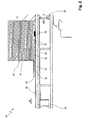
- the magazine initially comprises a storage space 11 which is bordered by storage box forming side walls 12.
- edge protection means 13 are kept, which are arranged vertically above one another with respect to a non-descript set-up level of the strapping device.
- Each edge protection means 13 initially has a contact surface 14 and a contact surface 15 opposite the contact surface.
- the contact surfaces 14 and counter surfaces 15 are arranged horizontally with respect to the mounting plane.
- the edge protection means 13 in the storage space 11 are thus contact surface 14 on counter surface 15 - forming a stack - one above the other.
- the edge protection means 13 are therefore stacked here as superimposed plates in the storage space 11.
- a support 16 forms below the edge protection means 13 arranged in the stack, a support surface 17, which limits the storage space 11 in the direction of gravity and on which the respectively provided for removal edge protection means 13 rests.
- removal direction x of the removal tool 18 the support surface 17 is followed by a conveying surface 19, which is also formed by the support 16 and on the the removed edge protection means 13 is moved by the removal tool 18.
- the magazine 10 further comprises a separating device, which initially comprises a gap 20, which is arranged between the support 16 and the front in the conveying direction x side wall 12 of the storage space 11.
- a separating device which initially comprises a gap 20, which is arranged between the support 16 and the front in the conveying direction x side wall 12 of the storage space 11.
- said front side wall 12 has been shortened and, in the embodiment shown here, provided with a hold-down limb 21, which is arranged approximately parallel to the conveying surface 19 in compliance with the gap dimension.
- the gap width corresponds at least to the material thickness of the respectively provided for removal edge protection means 13 so that it can be pushed by the removal tool 18 in the conveying direction x for removal from the storage space 11 through the gap 20.
- the front side wall 12 lying in the conveying direction x forms the claimed blockade element by retaining the further edge protection means 13 arranged above the edge protection means 13 for removal when the removal tool 18 moves in the conveying direction x.
- the removal tool 18 is set in motion-coupled manner on an endlessly circulating conveyor 22, in this case a toothed belt.
- the conveyor 22 itself is guided below the support 16.
- a non-illustrated movement gap for the removal tool 18 is formed, along which the removal tool 18 is movable.
- the removal tool 18 forms an approximately L-shaped receptacle 24, in which the provided for removal edge protection means 13th seated.
- a first aligned parallel to the main sides of the edge protection means 13 receiving leg engages under the provided for removal edge protection means 13, whereas a second receiving leg 26 abuts a transverse to the main sides narrow side 27 of the edge protection means 13.
- the main sides of the edge protection means 13 form the abutment surface 14 and the counter surface 15, respectively.
- the second receiving leg 26 corresponding in its length approximately to the material thickness of the edge protection means 13, that is to say the height of the narrow side 27, has a considerable depth in the conveying direction x.
- the support surface 28 of the second receiving leg 26, which is arranged parallel to the main sides and directed toward the advancing edge protection means 13 in the storage space 11, slides along the conveying edge x under the advancing edge protection means 13 and prevents premature retraction thereof.
- the second receiving leg 26 in the embodiment described here also serves as a support leg in the sense of the claim.
- the lowest intended for removal edge protection means 13 according to FIG. 1 sits in the L-shaped receptacle 24 and is advanced by the removal tool 18 in the conveying direction x, as in FIG. 2 shown. It slides on the conveying surface 19, which has a curved portion 29.
- This curved section 29 transfers the conveying surface 19 oriented substantially horizontally to the mounting plane of the strapping device into a substantially vertically aligned section adjoining the curvature.
- the curvature has a first radius.
- the curvature section begins approximately in the region of the forward deflection of the conveyor 22 arranged in the conveying direction x.
- the conveying means 22 is deflected in a second radius, which is preferably, and executed here in accordance with, smaller than the first radius of the curved portion 29 of the conveying surface 19.
- Wie aus FIG. 3 it can be seen, the removal tool 18 is a rigid body, the first receiving leg 25 is attached to the conveyor 22, whereas the second receiving leg 26 is lifted from the conveyor 22. This ensures in the rigid formation of the removal tool 18 initially the possibility of deflection, but as a result leads to an accelerated circulation of the second receiving leg 26 in the deflection of the conveyor 22 relative to the first receiving leg 25. This acceleration is transmitted to the subsidized edge protection means 13 and leads to an accelerated forward movement of the edge protection means 13 along the curved portion 29. In that regard, one can speak of an ejection of the edge protection means 13 from the removal tool 18.
- the acceleration of the edge protection means 13 is to ensure that it slides along the curved portion 29 of the conveying surface 19.
- the orientation of the edge protection means 13 with respect to the position in the storage space 11 is changed.
- the vertical position reached after sliding along the curvature section 29 in the present embodiment corresponds to the alignment required for the arrangement on the package.
- Other orientations of the Edge protection means 13 can also be achieved by a correspondingly changed course of curvature.
- the edge protection means 13 does not necessarily slide in the direction of gravity on the curved portion 29, even if this is certain to be advantageous.
- the curvature section 29 cooperates with a guide plate 30 which intercepts the narrow side 27 of the edge protection means 13 lying in the conveying direction x and supports the support in the desired end position.
- the main advantage of the curved conveying surface 19 is to be seen in the fact that it forms a deflection device for the edge protection means 13 in interaction with the removal tool 18 and the guide plate 30 in particular.
- this simpler physical conditions in particular the acceleration by the second receiving leg 26 and the gravity used to accomplish the deflection of the edge protection means 13 in a simple manner.
- the main advantage of this simple design diverter is the fact that the orientation of the storage space 11 of the magazine 10 and the orientation of the edge protection means 13 stored therein is independent of the orientation of the edge protection means 13 for the arrangement on the package. This makes it easier to arrange the storage space according to the object according to the invention without affecting the construction space on the strapping device.
Landscapes
- Engineering & Computer Science (AREA)
- Mechanical Engineering (AREA)
- Basic Packing Technique (AREA)
Claims (14)
- Cartouche (10) pour un dispositif de cerclage de paquets, dans lequel, en vue de la protection contre des endommagements du paquet, un moyen de protection de bords (13) est appliqué contre celui-ci avant l'opération de cerclage et le moyen de protection de bords (13) est retenu sur le paquet par le moyen de cerclage, le moyen de protection de bords (13) étant réalisé en forme de plaque et plusieurs moyens de protection de bords (13) étant tenus à disposition dans la cartouche (10) et étant retirés au besoin par un dispositif de retrait,- les moyens de protection de bords (13) étant disposés verticalement les uns sur les autres dans la cartouche (10) par rapport à un plan d'installation du dispositif de cerclage, les surfaces d'appui (14) respectives destinées à être agencées sur le paquet étant disposées horizontalement par rapport au plan d'installation,- le dispositif de retrait comprenant un outil de retrait (18), lequel retire le moyen de protection de bords (13) de la cartouche (10),- l'outil de retrait (18) étant retenu sur un moyen de transport (22) tournant sans fin, tel qu'une chaîne ou une bande, et étant guidé le long d'une trajectoire de déplacement, caractérisée en ce que l'outil de retrait (18) comprend une branche allongée dans le sens de déplacement, laquelle est fixée au moyen de transport (22) à son extrémité située à l'avant dans le sens de déplacement, son extrémité située à l'arrière dans le sens de déplacement étant cependant libre.
- Cartouche (10) selon la revendication 1, caractérisée en ce que la cartouche (10) comporte un dispositif de séparation, lequel sépare les moyens de protection de bords (13) tenus à disposition en vue du retrait.
- Cartouche (10) selon l'une quelconque des revendications précédentes, caractérisée en ce que le moyen de protection de bords (13) respectif prévu pour le retrait et se trouvant dans la cartouche (10) repose sur une surface de support (17).
- Cartouche (10) selon les revendications 2 et 3, caractérisée en ce que le dispositif de séparation est formé par un élément de blocage, lequel est disposé à une distance de la surface de support (17) qui correspond à au moins la hauteur du dispositif de protection de bords (13) et forme ainsi un interstice (20) entre l'élément de blocage et la surface de support (17).
- Cartouche (10) selon les revendications 3 et 4, caractérisée en ce que l'outil de retrait (18) pousse le moyen de protection de bords (13) reposant sur la surface de support (17) à travers l'interstice (20), et l'élément de blocage retient les moyens de protection de bords (13) restants.
- Cartouche (10) selon la revendication 3, caractérisée en ce qu'une surface de transport (19) se raccorde à la surface de support (17), le long de laquelle surface de transport le moyen de protection de bords (13) retiré de la cartouche (10) est déplacé par l'outil de retrait (18).
- Cartouche (10) selon la revendication 6, caractérisée en ce que la surface de transport (19) est courbée autour d'un axe disposé transversalement au sens de déplacement du moyen de protection de bords (13) et horizontalement par rapport à la surface d'installation, afin d'amener le moyen de protection de bords (13) à une position correspondant à l'agencement sur le paquet.
- Cartouche (10) selon la revendication 7, caractérisée en ce que la surface de transport (19) passe, au moyen de la courbure, d'une portion essentiellement horizontale par rapport au plan d'installation à une portion essentiellement verticale.
- Cartouche (10) selon la revendication 8, caractérisée en ce que le moyen de transport (22) est dévié dans la région de la transition de la portion horizontale à la portion courbée (29).
- Cartouche (10) selon la revendication 9, caractérisée en ce que le rayon de déviation du moyen de transport (22) est inférieur au rayon de courbure de la surface de transport (19).
- Cartouche (10) selon la revendication 1, caractérisée en ce que l'outil de retrait (18) comprend un logement (24) essentiellement en forme de L, dans lequel est logé le moyen de protection de bords (13) pendant le déplacement le long d'au moins une partie de la surface de transport (19).
- Cartouche (10) selon la revendication 9, caractérisée en ce que le moyen de protection de bords (13) est, dans la région de la déviation du moyen de transport (22), éjecté hors de l'outil de retrait (18), l'extrémité libre de la branche de l'outil de retrait (18) accélérant le moyen de protection de bords (13) au moyen de la vitesse de déplacement plus élevée dans la région de déviation.
- Cartouche (10) selon la revendication 7, caractérisée en ce qu'il est prévu un organe de guidage, tel qu'une tôle de guidage (30), lequel coopère avec la portion courbée (29), afin de stabiliser le moyen de protection de bords (13) dans sa position correspondant à l'agencement sur le paquet.
- Cartouche (10) selon la revendication 5, caractérisée en ce que l'outil de retrait (18) porte une branche de support qui, lors du retrait d'un moyen de protection de bords (13), s'applique contre le moyen de protection de bords (13) avançant dans la cartouche (10) et empêche un avancement prématuré.
Applications Claiming Priority (1)
| Application Number | Priority Date | Filing Date | Title |
|---|---|---|---|
| DE102012016657.5A DE102012016657A1 (de) | 2012-08-24 | 2012-08-24 | Magazin für eine Umreifungsvorrichtung |
Publications (2)
| Publication Number | Publication Date |
|---|---|
| EP2700577A1 EP2700577A1 (fr) | 2014-02-26 |
| EP2700577B1 true EP2700577B1 (fr) | 2014-10-22 |
Family
ID=48985537
Family Applications (1)
| Application Number | Title | Priority Date | Filing Date |
|---|---|---|---|
| EP13003941.5A Active EP2700577B1 (fr) | 2012-08-24 | 2013-08-07 | Cartouche pour dispositif de cerclage |
Country Status (3)
| Country | Link |
|---|---|
| EP (1) | EP2700577B1 (fr) |
| DE (1) | DE102012016657A1 (fr) |
| ES (1) | ES2528002T3 (fr) |
Cited By (4)
| Publication number | Priority date | Publication date | Assignee | Title |
|---|---|---|---|---|
| US10926902B2 (en) | 2015-08-13 | 2021-02-23 | Signode Industrial Group Llc | Strapping apparatus for packages and strapping method |
| US11618599B2 (en) | 2019-07-03 | 2023-04-04 | Signode Industrial Group Llc | Strapping machine including an edge-protector magazine having a telescopic rail assembly |
| US11691770B2 (en) | 2019-03-26 | 2023-07-04 | Signode Industrial Group Llc | Method for positioning an edge-protector and apparatus for strapping packages |
| US11801954B2 (en) | 2019-08-14 | 2023-10-31 | Signode Industrial Group Llc | Strapping machine with improved edge-protector-positioner |
Families Citing this family (5)
| Publication number | Priority date | Publication date | Assignee | Title |
|---|---|---|---|---|
| US10099808B2 (en) | 2014-12-01 | 2018-10-16 | Signode Industrial Group Llc | Apparatus and method for forming and applying edge protectors |
| US11491752B2 (en) | 2018-11-01 | 2022-11-08 | Signode Industrial Group Llc | Press-type strapping machine with improved top-platen control |
| CN111941931B (zh) * | 2020-07-28 | 2022-07-12 | 谭小红 | 一种书型盒粘接装置 |
| US12612202B2 (en) | 2021-07-29 | 2026-04-28 | Signode Industrial Group Llc | System for compressing and strapping loads with press-type strapping machines having improved platen control |
| WO2026101752A1 (fr) | 2024-11-05 | 2026-05-15 | Signode Industrial Group Llc | Cercleuse à applicateur à protection de bord |
Family Cites Families (12)
| Publication number | Priority date | Publication date | Assignee | Title |
|---|---|---|---|---|
| BE644509A (fr) * | 1963-03-20 | 1964-06-15 | ||
| FR85283E (fr) * | 1963-06-26 | 1965-07-09 | Machine automatique à encercler les emballages, paquets | |
| US3995409A (en) * | 1975-05-02 | 1976-12-07 | Fmc Corporation | Strapping apparatus |
| JPS58134819A (ja) * | 1983-01-11 | 1983-08-11 | 凸版印刷株式会社 | 自動結束機における被結束物導入方法 |
| JPS61145047A (ja) * | 1984-12-17 | 1986-07-02 | Muneharu Fukumoto | 搬送装置 |
| GB8800129D0 (en) * | 1988-01-05 | 1988-02-10 | Sills A W | Card feeder |
| DE9311406U1 (de) * | 1993-07-30 | 1993-11-11 | Cyklop GmbH, 50996 Köln | Packpresse |
| US5596863A (en) * | 1995-06-12 | 1997-01-28 | Illinois Tool Works Inc. | Method and apparatus for applying edge protectors |
| JP2955747B2 (ja) * | 1996-08-28 | 1999-10-04 | 東晃鋼業株式会社 | バンド掛け装置 |
| DE202004015190U1 (de) * | 2004-09-30 | 2004-11-25 | Kolbus Gmbh & Co. Kg | Magazin für gestapelte Zuschnitte aus Pappe, Karton o.dgl. |
| US7428865B1 (en) * | 2007-09-24 | 2008-09-30 | Illinois Tool Works Inc. | Press-type strapping machine |
| DE202012004335U1 (de) | 2012-05-03 | 2013-08-08 | Itw Packaging Systems Group Gmbh | Vorrichtung zum Umreifen von Packstücken |
-
2012
- 2012-08-24 DE DE102012016657.5A patent/DE102012016657A1/de not_active Withdrawn
-
2013
- 2013-08-07 EP EP13003941.5A patent/EP2700577B1/fr active Active
- 2013-08-07 ES ES13003941.5T patent/ES2528002T3/es active Active
Cited By (4)
| Publication number | Priority date | Publication date | Assignee | Title |
|---|---|---|---|---|
| US10926902B2 (en) | 2015-08-13 | 2021-02-23 | Signode Industrial Group Llc | Strapping apparatus for packages and strapping method |
| US11691770B2 (en) | 2019-03-26 | 2023-07-04 | Signode Industrial Group Llc | Method for positioning an edge-protector and apparatus for strapping packages |
| US11618599B2 (en) | 2019-07-03 | 2023-04-04 | Signode Industrial Group Llc | Strapping machine including an edge-protector magazine having a telescopic rail assembly |
| US11801954B2 (en) | 2019-08-14 | 2023-10-31 | Signode Industrial Group Llc | Strapping machine with improved edge-protector-positioner |
Also Published As
| Publication number | Publication date |
|---|---|
| EP2700577A1 (fr) | 2014-02-26 |
| ES2528002T3 (es) | 2015-02-03 |
| DE102012016657A1 (de) | 2014-02-27 |
Similar Documents
| Publication | Publication Date | Title |
|---|---|---|
| EP2700577A1 (fr) | Cartouche pour dispositif de cerclage | |
| EP2700578B1 (fr) | Dispositif de cerclage des paquets | |
| EP3025970B1 (fr) | Dispositif de cerclage de produits empiles | |
| EP2520500A1 (fr) | Station de découpage avec unité de découpage | |
| EP3012196A1 (fr) | Dispositif pour l'agencement d'un moyen de protection de bords et dispositif de cerclage de pièces d'emballage à l'aide dudit dispositif | |
| EP3133034A1 (fr) | Dispositif et procede d'acheminement de produits | |
| EP3566985B1 (fr) | Dispositif d'empilement de plateaux pourvu d'un moyen de décharge | |
| EP2865618A1 (fr) | Dispositif pour transférer des piles d' emballages blister | |
| DE102015113350A1 (de) | Umreifungsvorrichtung für Packstücke und Verfahren zum Umreifen | |
| DE3716666C2 (de) | Plattenaufteilanlage mit einer Längssäge und einer Quersäge | |
| DE102004050197A1 (de) | Einschubeinheit zum Einschieben eines Produktes in ein Verpackungsbehältnis | |
| DE102011114240A1 (de) | Vorrichtung zum Handhaben von Zuschnitten | |
| DE102012025608B4 (de) | Einrichtung zur Anordnung eines Kantensschutzes an einem Packstück | |
| EP2878541A1 (fr) | Avancée pour un moyen de protection d'arêtes dans un dispositif de cerclage | |
| DE19505997A1 (de) | Eingruppierung | |
| EP3590850B1 (fr) | Procédé et dispositif d'empilement et d'emballage de produits pliés | |
| DE202012008091U1 (de) | Magazin für eine Umreifungsvorrichtung | |
| DE9311406U1 (de) | Packpresse | |
| EP3042867B1 (fr) | Appareil de commande pour un dispositif de préparation de commandes | |
| EP2994402B1 (fr) | Manipulateur | |
| DE19920614A1 (de) | Verpackungsmaschine | |
| CH443114A (de) | F¦rdervorrichtung für Kartoniermaschinen oder andere Verpackungsmaschinen | |
| DE202012008064U1 (de) | Vortrieb für ein Kantenschutzmittel in einer Umreifungsvorrichtung | |
| DE102015113353B4 (de) | Umreifungsvorrichtung | |
| DE2640050A1 (de) | Bandumwindungsvorrichtung an einer verpackungsmaschine |
Legal Events
| Date | Code | Title | Description |
|---|---|---|---|
| PUAI | Public reference made under article 153(3) epc to a published international application that has entered the european phase |
Free format text: ORIGINAL CODE: 0009012 |
|
| AK | Designated contracting states |
Kind code of ref document: A1 Designated state(s): AL AT BE BG CH CY CZ DE DK EE ES FI FR GB GR HR HU IE IS IT LI LT LU LV MC MK MT NL NO PL PT RO RS SE SI SK SM TR |
|
| AX | Request for extension of the european patent |
Extension state: BA ME |
|
| 17P | Request for examination filed |
Effective date: 20140319 |
|
| RBV | Designated contracting states (corrected) |
Designated state(s): AL AT BE BG CH CY CZ DE DK EE ES FI FR GB GR HR HU IE IS IT LI LT LU LV MC MK MT NL NO PL PT RO RS SE SI SK SM TR |
|
| GRAP | Despatch of communication of intention to grant a patent |
Free format text: ORIGINAL CODE: EPIDOSNIGR1 |
|
| INTG | Intention to grant announced |
Effective date: 20140604 |
|
| GRAS | Grant fee paid |
Free format text: ORIGINAL CODE: EPIDOSNIGR3 |
|
| GRAA | (expected) grant |
Free format text: ORIGINAL CODE: 0009210 |
|
| RAP1 | Party data changed (applicant data changed or rights of an application transferred) |
Owner name: SPG PACKAGING SYSTEMS GMBH |
|
| AK | Designated contracting states |
Kind code of ref document: B1 Designated state(s): AL AT BE BG CH CY CZ DE DK EE ES FI FR GB GR HR HU IE IS IT LI LT LU LV MC MK MT NL NO PL PT RO RS SE SI SK SM TR |
|
| REG | Reference to a national code |
Ref country code: GB Ref legal event code: FG4D Free format text: NOT ENGLISH |
|
| REG | Reference to a national code |
Ref country code: CH Ref legal event code: EP |
|
| REG | Reference to a national code |
Ref country code: AT Ref legal event code: REF Ref document number: 692506 Country of ref document: AT Kind code of ref document: T Effective date: 20141115 |
|
| REG | Reference to a national code |
Ref country code: IE Ref legal event code: FG4D Free format text: LANGUAGE OF EP DOCUMENT: GERMAN |
|
| REG | Reference to a national code |
Ref country code: DE Ref legal event code: R096 Ref document number: 502013000138 Country of ref document: DE Effective date: 20141204 |
|
| REG | Reference to a national code |
Ref country code: ES Ref legal event code: FG2A Ref document number: 2528002 Country of ref document: ES Kind code of ref document: T3 Effective date: 20150203 |
|
| REG | Reference to a national code |
Ref country code: NL Ref legal event code: VDEP Effective date: 20141022 |
|
| REG | Reference to a national code |
Ref country code: LT Ref legal event code: MG4D |
|
| PG25 | Lapsed in a contracting state [announced via postgrant information from national office to epo] |
Ref country code: NO Free format text: LAPSE BECAUSE OF FAILURE TO SUBMIT A TRANSLATION OF THE DESCRIPTION OR TO PAY THE FEE WITHIN THE PRESCRIBED TIME-LIMIT Effective date: 20150122 Ref country code: LT Free format text: LAPSE BECAUSE OF FAILURE TO SUBMIT A TRANSLATION OF THE DESCRIPTION OR TO PAY THE FEE WITHIN THE PRESCRIBED TIME-LIMIT Effective date: 20141022 Ref country code: FI Free format text: LAPSE BECAUSE OF FAILURE TO SUBMIT A TRANSLATION OF THE DESCRIPTION OR TO PAY THE FEE WITHIN THE PRESCRIBED TIME-LIMIT Effective date: 20141022 Ref country code: PT Free format text: LAPSE BECAUSE OF FAILURE TO SUBMIT A TRANSLATION OF THE DESCRIPTION OR TO PAY THE FEE WITHIN THE PRESCRIBED TIME-LIMIT Effective date: 20150223 Ref country code: IS Free format text: LAPSE BECAUSE OF FAILURE TO SUBMIT A TRANSLATION OF THE DESCRIPTION OR TO PAY THE FEE WITHIN THE PRESCRIBED TIME-LIMIT Effective date: 20150222 Ref country code: NL Free format text: LAPSE BECAUSE OF FAILURE TO SUBMIT A TRANSLATION OF THE DESCRIPTION OR TO PAY THE FEE WITHIN THE PRESCRIBED TIME-LIMIT Effective date: 20141022 |
|
| PG25 | Lapsed in a contracting state [announced via postgrant information from national office to epo] |
Ref country code: LV Free format text: LAPSE BECAUSE OF FAILURE TO SUBMIT A TRANSLATION OF THE DESCRIPTION OR TO PAY THE FEE WITHIN THE PRESCRIBED TIME-LIMIT Effective date: 20141022 Ref country code: PL Free format text: LAPSE BECAUSE OF FAILURE TO SUBMIT A TRANSLATION OF THE DESCRIPTION OR TO PAY THE FEE WITHIN THE PRESCRIBED TIME-LIMIT Effective date: 20141022 Ref country code: RS Free format text: LAPSE BECAUSE OF FAILURE TO SUBMIT A TRANSLATION OF THE DESCRIPTION OR TO PAY THE FEE WITHIN THE PRESCRIBED TIME-LIMIT Effective date: 20141022 Ref country code: SE Free format text: LAPSE BECAUSE OF FAILURE TO SUBMIT A TRANSLATION OF THE DESCRIPTION OR TO PAY THE FEE WITHIN THE PRESCRIBED TIME-LIMIT Effective date: 20141022 Ref country code: CY Free format text: LAPSE BECAUSE OF FAILURE TO SUBMIT A TRANSLATION OF THE DESCRIPTION OR TO PAY THE FEE WITHIN THE PRESCRIBED TIME-LIMIT Effective date: 20141022 Ref country code: HR Free format text: LAPSE BECAUSE OF FAILURE TO SUBMIT A TRANSLATION OF THE DESCRIPTION OR TO PAY THE FEE WITHIN THE PRESCRIBED TIME-LIMIT Effective date: 20141022 Ref country code: GR Free format text: LAPSE BECAUSE OF FAILURE TO SUBMIT A TRANSLATION OF THE DESCRIPTION OR TO PAY THE FEE WITHIN THE PRESCRIBED TIME-LIMIT Effective date: 20150123 |
|
| REG | Reference to a national code |
Ref country code: DE Ref legal event code: R097 Ref document number: 502013000138 Country of ref document: DE |
|
| PG25 | Lapsed in a contracting state [announced via postgrant information from national office to epo] |
Ref country code: EE Free format text: LAPSE BECAUSE OF FAILURE TO SUBMIT A TRANSLATION OF THE DESCRIPTION OR TO PAY THE FEE WITHIN THE PRESCRIBED TIME-LIMIT Effective date: 20141022 Ref country code: RO Free format text: LAPSE BECAUSE OF FAILURE TO SUBMIT A TRANSLATION OF THE DESCRIPTION OR TO PAY THE FEE WITHIN THE PRESCRIBED TIME-LIMIT Effective date: 20141022 Ref country code: CZ Free format text: LAPSE BECAUSE OF FAILURE TO SUBMIT A TRANSLATION OF THE DESCRIPTION OR TO PAY THE FEE WITHIN THE PRESCRIBED TIME-LIMIT Effective date: 20141022 Ref country code: DK Free format text: LAPSE BECAUSE OF FAILURE TO SUBMIT A TRANSLATION OF THE DESCRIPTION OR TO PAY THE FEE WITHIN THE PRESCRIBED TIME-LIMIT Effective date: 20141022 Ref country code: SK Free format text: LAPSE BECAUSE OF FAILURE TO SUBMIT A TRANSLATION OF THE DESCRIPTION OR TO PAY THE FEE WITHIN THE PRESCRIBED TIME-LIMIT Effective date: 20141022 |
|
| REG | Reference to a national code |
Ref country code: FR Ref legal event code: PLFP Year of fee payment: 3 |
|
| PLBE | No opposition filed within time limit |
Free format text: ORIGINAL CODE: 0009261 |
|
| STAA | Information on the status of an ep patent application or granted ep patent |
Free format text: STATUS: NO OPPOSITION FILED WITHIN TIME LIMIT |
|
| 26N | No opposition filed |
Effective date: 20150723 |
|
| PG25 | Lapsed in a contracting state [announced via postgrant information from national office to epo] |
Ref country code: SI Free format text: LAPSE BECAUSE OF FAILURE TO SUBMIT A TRANSLATION OF THE DESCRIPTION OR TO PAY THE FEE WITHIN THE PRESCRIBED TIME-LIMIT Effective date: 20141022 |
|
| PG25 | Lapsed in a contracting state [announced via postgrant information from national office to epo] |
Ref country code: LU Free format text: LAPSE BECAUSE OF FAILURE TO SUBMIT A TRANSLATION OF THE DESCRIPTION OR TO PAY THE FEE WITHIN THE PRESCRIBED TIME-LIMIT Effective date: 20150807 Ref country code: MC Free format text: LAPSE BECAUSE OF FAILURE TO SUBMIT A TRANSLATION OF THE DESCRIPTION OR TO PAY THE FEE WITHIN THE PRESCRIBED TIME-LIMIT Effective date: 20141022 |
|
| REG | Reference to a national code |
Ref country code: IE Ref legal event code: MM4A |
|
| PG25 | Lapsed in a contracting state [announced via postgrant information from national office to epo] |
Ref country code: IE Free format text: LAPSE BECAUSE OF NON-PAYMENT OF DUE FEES Effective date: 20150807 |
|
| REG | Reference to a national code |
Ref country code: FR Ref legal event code: PLFP Year of fee payment: 4 |
|
| PG25 | Lapsed in a contracting state [announced via postgrant information from national office to epo] |
Ref country code: MT Free format text: LAPSE BECAUSE OF FAILURE TO SUBMIT A TRANSLATION OF THE DESCRIPTION OR TO PAY THE FEE WITHIN THE PRESCRIBED TIME-LIMIT Effective date: 20141022 |
|
| PG25 | Lapsed in a contracting state [announced via postgrant information from national office to epo] |
Ref country code: BG Free format text: LAPSE BECAUSE OF FAILURE TO SUBMIT A TRANSLATION OF THE DESCRIPTION OR TO PAY THE FEE WITHIN THE PRESCRIBED TIME-LIMIT Effective date: 20141022 Ref country code: HU Free format text: LAPSE BECAUSE OF FAILURE TO SUBMIT A TRANSLATION OF THE DESCRIPTION OR TO PAY THE FEE WITHIN THE PRESCRIBED TIME-LIMIT; INVALID AB INITIO Effective date: 20130807 |
|
| PG25 | Lapsed in a contracting state [announced via postgrant information from national office to epo] |
Ref country code: BE Free format text: LAPSE BECAUSE OF NON-PAYMENT OF DUE FEES Effective date: 20150831 |
|
| REG | Reference to a national code |
Ref country code: FR Ref legal event code: PLFP Year of fee payment: 5 |
|
| GBPC | Gb: european patent ceased through non-payment of renewal fee |
Effective date: 20170807 |
|
| PG25 | Lapsed in a contracting state [announced via postgrant information from national office to epo] |
Ref country code: SM Free format text: LAPSE BECAUSE OF FAILURE TO SUBMIT A TRANSLATION OF THE DESCRIPTION OR TO PAY THE FEE WITHIN THE PRESCRIBED TIME-LIMIT Effective date: 20141022 |
|
| PG25 | Lapsed in a contracting state [announced via postgrant information from national office to epo] |
Ref country code: MK Free format text: LAPSE BECAUSE OF FAILURE TO SUBMIT A TRANSLATION OF THE DESCRIPTION OR TO PAY THE FEE WITHIN THE PRESCRIBED TIME-LIMIT Effective date: 20141022 |
|
| PG25 | Lapsed in a contracting state [announced via postgrant information from national office to epo] |
Ref country code: GB Free format text: LAPSE BECAUSE OF NON-PAYMENT OF DUE FEES Effective date: 20170807 |
|
| REG | Reference to a national code |
Ref country code: FR Ref legal event code: PLFP Year of fee payment: 6 |
|
| PG25 | Lapsed in a contracting state [announced via postgrant information from national office to epo] |
Ref country code: AL Free format text: LAPSE BECAUSE OF FAILURE TO SUBMIT A TRANSLATION OF THE DESCRIPTION OR TO PAY THE FEE WITHIN THE PRESCRIBED TIME-LIMIT Effective date: 20141022 |
|
| REG | Reference to a national code |
Ref country code: AT Ref legal event code: MM01 Ref document number: 692506 Country of ref document: AT Kind code of ref document: T Effective date: 20180807 |
|
| PG25 | Lapsed in a contracting state [announced via postgrant information from national office to epo] |
Ref country code: AT Free format text: LAPSE BECAUSE OF NON-PAYMENT OF DUE FEES Effective date: 20180807 |
|
| PGFP | Annual fee paid to national office [announced via postgrant information from national office to epo] |
Ref country code: FR Payment date: 20200825 Year of fee payment: 8 Ref country code: TR Payment date: 20200723 Year of fee payment: 8 Ref country code: ES Payment date: 20200901 Year of fee payment: 8 |
|
| PGFP | Annual fee paid to national office [announced via postgrant information from national office to epo] |
Ref country code: IT Payment date: 20200821 Year of fee payment: 8 Ref country code: CH Payment date: 20200903 Year of fee payment: 8 |
|
| REG | Reference to a national code |
Ref country code: CH Ref legal event code: PL |
|
| PG25 | Lapsed in a contracting state [announced via postgrant information from national office to epo] |
Ref country code: LI Free format text: LAPSE BECAUSE OF NON-PAYMENT OF DUE FEES Effective date: 20210831 Ref country code: CH Free format text: LAPSE BECAUSE OF NON-PAYMENT OF DUE FEES Effective date: 20210831 |
|
| PG25 | Lapsed in a contracting state [announced via postgrant information from national office to epo] |
Ref country code: IT Free format text: LAPSE BECAUSE OF NON-PAYMENT OF DUE FEES Effective date: 20210807 Ref country code: FR Free format text: LAPSE BECAUSE OF NON-PAYMENT OF DUE FEES Effective date: 20210831 |
|
| REG | Reference to a national code |
Ref country code: ES Ref legal event code: FD2A Effective date: 20221028 |
|
| PG25 | Lapsed in a contracting state [announced via postgrant information from national office to epo] |
Ref country code: ES Free format text: LAPSE BECAUSE OF NON-PAYMENT OF DUE FEES Effective date: 20210808 |
|
| PG25 | Lapsed in a contracting state [announced via postgrant information from national office to epo] |
Ref country code: TR Free format text: LAPSE BECAUSE OF NON-PAYMENT OF DUE FEES Effective date: 20210807 |
|
| PGFP | Annual fee paid to national office [announced via postgrant information from national office to epo] |
Ref country code: DE Payment date: 20250724 Year of fee payment: 13 |