EP2700613A1 - Verstellvorrichtung für eine Getränkeabfüllanlage sowie Verfahren zur Reinigung einer Verstellvorrichtung - Google Patents
Verstellvorrichtung für eine Getränkeabfüllanlage sowie Verfahren zur Reinigung einer Verstellvorrichtung Download PDFInfo
- Publication number
- EP2700613A1 EP2700613A1 EP13181546.6A EP13181546A EP2700613A1 EP 2700613 A1 EP2700613 A1 EP 2700613A1 EP 13181546 A EP13181546 A EP 13181546A EP 2700613 A1 EP2700613 A1 EP 2700613A1
- Authority
- EP
- European Patent Office
- Prior art keywords
- adjusting device
- cleaning
- rotation
- translation
- translation element
- Prior art date
- Legal status (The legal status is an assumption and is not a legal conclusion. Google has not performed a legal analysis and makes no representation as to the accuracy of the status listed.)
- Granted
Links
Images


Classifications
-
- B—PERFORMING OPERATIONS; TRANSPORTING
- B67—OPENING, CLOSING OR CLEANING BOTTLES, JARS OR SIMILAR CONTAINERS; LIQUID HANDLING
- B67C—CLEANING, FILLING WITH LIQUIDS OR SEMILIQUIDS, OR EMPTYING, OF BOTTLES, JARS, CANS, CASKS, BARRELS, OR SIMILAR CONTAINERS, NOT OTHERWISE PROVIDED FOR; FUNNELS
- B67C3/00—Bottling liquids or semiliquids; Filling jars or cans with liquids or semiliquids using bottling or like apparatus; Filling casks or barrels with liquids or semiliquids
- B67C3/02—Bottling liquids or semiliquids; Filling jars or cans with liquids or semiliquids using bottling or like apparatus
- B67C3/22—Details
-
- B—PERFORMING OPERATIONS; TRANSPORTING
- B65—CONVEYING; PACKING; STORING; HANDLING THIN OR FILAMENTARY MATERIAL
- B65G—TRANSPORT OR STORAGE DEVICES, e.g. CONVEYORS FOR LOADING OR TIPPING, SHOP CONVEYOR SYSTEMS OR PNEUMATIC TUBE CONVEYORS
- B65G21/00—Supporting or protective framework or housings for endless load-carriers or traction elements of belt or chain conveyors
- B65G21/20—Means incorporated in, or attached to, framework or housings for guiding load-carriers, traction elements or loads supported on moving surfaces
- B65G21/2045—Mechanical means for guiding or retaining the load on the load-carrying surface
- B65G21/2063—Mechanical means for guiding or retaining the load on the load-carrying surface comprising elements not movable in the direction of load-transport
- B65G21/2072—Laterial guidance means
-
- B—PERFORMING OPERATIONS; TRANSPORTING
- B65—CONVEYING; PACKING; STORING; HANDLING THIN OR FILAMENTARY MATERIAL
- B65G—TRANSPORT OR STORAGE DEVICES, e.g. CONVEYORS FOR LOADING OR TIPPING, SHOP CONVEYOR SYSTEMS OR PNEUMATIC TUBE CONVEYORS
- B65G47/00—Article or material-handling devices associated with conveyors; Methods employing such devices
- B65G47/74—Feeding, transfer, or discharging devices of particular kinds or types
- B65G47/84—Star-shaped wheels or devices having endless travelling belts or chains, the wheels or devices being equipped with article-engaging elements
- B65G47/846—Star-shaped wheels or wheels equipped with article-engaging elements
-
- B—PERFORMING OPERATIONS; TRANSPORTING
- B67—OPENING, CLOSING OR CLEANING BOTTLES, JARS OR SIMILAR CONTAINERS; LIQUID HANDLING
- B67B—APPLYING CLOSURE MEMBERS TO BOTTLES JARS, OR SIMILAR CONTAINERS; OPENING CLOSED CONTAINERS
- B67B2201/00—Indexing codes relating to constructional features of closing machines
- B67B2201/08—Aseptic features
-
- B—PERFORMING OPERATIONS; TRANSPORTING
- B67—OPENING, CLOSING OR CLEANING BOTTLES, JARS OR SIMILAR CONTAINERS; LIQUID HANDLING
- B67C—CLEANING, FILLING WITH LIQUIDS OR SEMILIQUIDS, OR EMPTYING, OF BOTTLES, JARS, CANS, CASKS, BARRELS, OR SIMILAR CONTAINERS, NOT OTHERWISE PROVIDED FOR; FUNNELS
- B67C3/00—Bottling liquids or semiliquids; Filling jars or cans with liquids or semiliquids using bottling or like apparatus; Filling casks or barrels with liquids or semiliquids
- B67C3/02—Bottling liquids or semiliquids; Filling jars or cans with liquids or semiliquids using bottling or like apparatus
- B67C3/22—Details
- B67C2003/228—Aseptic features
Definitions
- the present invention relates to an adjusting device for a beverage filling plant for adjusting the position of machine elements relative to one another, and to a method for cleaning such an adjusting device.
- adjusting devices For adjusting individual machine elements relative to each other, in particular in the field of beverage filling plants, it is known to adjust the machine elements against each other via adjusting devices.
- adjusting devices serve, for example, hydraulic or pneumatic cylinders, engine cylinders or screw drives, such as spindle drives.
- a particularly simple adjusting device for applying linear movements to machine elements is realized by a threaded spindle and a matching threaded nut.
- a threaded spindle rotates and the threaded nut does not rotate, a linear translation of the threaded nut is achieved along the threaded spindle. This linear displacement of the threaded nut along the threaded spindle is used to transmit the linear adjustment movement.
- a bellows is an extremely sensitive component whose tightness must be constantly monitored. Furthermore, bellows have a large volume and the connection of a bellows to the respective machine elements can only be achieved consuming in a hygienic way. A bellows is still another component, which represents a cost point accordingly.
- bellows The material typically used in bellows is plastic, which is poorly dryable, which can be critical in gaseous insulator sterilization. When using bellows made of metal, however, a large installation space is needed.
- a universal closing machine for the application of caps on containers in which the height adjustment of an upper part of the universal closing machine is achieved with respect to a lower part via a spindle drive which is sealed by a bellows.
- the adjustment device for a beverage filling installation comprises a rotation element and a translation element that is translationally movable relative to this by rotation of the rotation element.
- the rotation element and / or the translation element preferably the rotation element or the rotation element and the translation element, at least one cleaning recess for cleaning a contact region between the translation element and the rotation element.
- the cleaning recess in the rotation element and / or the translation element it is possible, also the contact region of the adjusting device, which between the translation element and the rotation element is to rinse, clean, dry and / or sterilize.
- an outwardly open groove extending in the direction of the rotation axis may be incorporated in the rotation element, by means of which it is achieved that the contact area between the rotation element and the translation element is completely and continuously swept over by the groove during rotation of the rotation element.
- a treatment medium for example a sterilization medium, can penetrate into the contact region of the translation element, such that the translation element can also be completely treated, preferably rinsed, cleaned, dried and sterilized in the area of contact with the rotation element.
- this complete treatment of the surfaces can be achieved with a corresponding design of the cleaning recess. This can be achieved, for example, by entraining the treatment liquid through the contact surface between the translation element and the rotation element.
- the rotation element is designed as a threaded spindle and the translation element as a complementary nut.
- Such a design of an adjusting mechanism is easy to use in the field of beverage filling equipment, since the previous spindle drives are easily replaced by the spindle drive according to the invention can then be dispensed with the seal by means of a bellows.
- the at least one cleaning recess is preferably provided as a radially outwardly open groove in the threaded spindle in the formation of a spindle drive.
- This open groove then sweeps over the entire inner region of the threaded nut during the rotation of the rotary element such that not only the threaded spindle can undergo complete treatment by displacing the threaded nut along the axis of rotation, but also the interior of the threaded nut can be completely sterilized.
- the open groove When the open groove is formed, for example, as a straight groove extending along the axis of rotation, the groove completely sweeps over the inner surface or the inner thread of the threaded nut, similar to the light beam of a lighthouse.
- cleaning recess are conceivable, for example in the form of a helix, which preferably has a different slope than the pitch of the actual thread, wherein in such an expression of the cleaning recess according to an advantageous effect with respect to the delivery of the sterilization medium the threaded nut can be reached through.
- the pitch of such a helix can be either in the same direction with the thread of the rotary element, or in the opposite direction (left, right-hand thread).
- cleaning recesses arranged perpendicularly to the rotation axis of the rotation element, which then transport the cleaning liquid or the sterilization medium through the threaded nut, cleaning media which show a corresponding adhesion in the respective cleaning recesses being used in a particularly preferred manner for a corresponding transport to allow through the threaded nut.
- the internal thread in addition to the actual threads additionally has a cleaning recess, which is for example helically impressed, and which makes it possible to bring the cleaning liquid or the sterilization medium during rotation between the rotation element and translation element. In this way it can be achieved that all contact surfaces via a driving of the corresponding cleaning or sterilization media by the rotation of the rotary member or contact areas between the mutually moving elements are exposed to the media and thus cleaned or sterilized.
- inner and outer edges of threads are rounded or at least bevelled. This increases cleanability, prevents media from adhering easily, and meets national or international hygiene standards, such as EHEDG or 3A design requirements.
- the rotation element or the translation element is provided with a non-constant diameter and, for example, elliptical or provided with at least one flattening, so that a flow through the contact area between the translation element and rotating element with cleaning liquid or sterilization medium is possible.
- the method for cleaning a previously described adjusting device comprises applying the adjusting device with a cleaning fluid, a drying medium and / or a sterilization medium.
- the rotating element is rotated during the loading of the adjusting device with cleaning liquid, drying medium and / or sterilizing medium.
- the proposed adjusting device can accordingly be used as an open construction in a clean room or an isolator of a beverage bottling plant and, in particular, in an aseptic beverage bottling plant, since all the components and all surfaces in contact with the clean room or the insulator can be reliably cleaned or sterilized.
- drives for the adjusting device can be arranged outside of the insulator, wherein only a seal of the rotational movement, for example by a simple shaft seal, is necessary.
- the proposed adjustment device is an efficient way to provide a linear adjustment within a beverage bottling plant or, in particular, an aseptic beverage bottling plant. Furthermore, the corresponding linear adjustment can be accomplished even in the smallest space, since the voluminous attachments, which are necessary to connect the bellows, as well as the bulky bellows can be dispensed with.
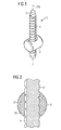
- FIG. 1 shows a schematic perspective view of an adjusting device 1, which has a rotary member 2 in the form of a threaded spindle and a translation element 3 in the form of a threaded nut.
- adjusting device 1 is accordingly a spindle drive, which is for example used to allow a linear adjustment between two machine elements of a beverage filling plant.
- a cleaning recess 4 is provided, which in the in FIG. 1 shown embodiment in the form of a extending in the direction of the axis of rotation 200 of the rotary member 2 and is formed outwardly open groove.
- the cleaning recess 4 is configured such that during a rotation of the rotary element 2 the contact area present between the rotary element 2 and the translation element 3 is swept by the cleaning recess 4 within the translational element 3. This makes it possible, as in the in FIG. 1 shown embodiment, a cleaning liquid, a drying medium and / or a sterilization medium by the cleaning recess 4 also apply to all internal surfaces of the translation element 3, to allow complete cleaning of all surfaces. In other words, the internal thread of the translation element 3 can be cleaned, dried and sterilized.
- the adjusting device 1 for example, in an isolator of a beverage filling plant, in particular an aseptic beverage filling plant, since All surfaces can be cleaned and sterilized and accordingly no hidden areas can occur which could injure the sterile area.
- the cleaning recess 4 is preferably dimensioned so that it can receive or transport a volume of liquid or media volume which is sufficient for the proper rinsing, cleaning, drying and / or sterilization of the insides of the translation element 3.
- the cleaning recess is not necessarily over the entire length of the rotation element, such as in FIG. 1 shown must extend.
- the cleaning recess may also be arranged only on, for example, an upper or lower end of the rotation element.
- the length of the cleaning recess on the rotary element is advantageously chosen so that at least one revolution of the rotary element and each area of the inside of the translation element is swept over at least once by the cleaning recess.
- the cleaning recess 4 can also be formed in that the rotary member has a substantially non-circular cross-sectional area.
- one-sided flattenings can be arranged along the rotation element or even multi-sided flattenings can be arranged along the rotation element, which lead, for example, to a trigonal or hexagonal etc. cross-section.
- the flats can not only have a flat surface, but also be curved, for example, so that the cross section of the rotary element, for example, receives an ellipse-like shape.
- the materials of the translation element 3 and the rotation element 2 are preferably matched to one another such that lubrication of the contact surfaces can be dispensed with. Accordingly, even after cleaning and sterilization of the threaded portions of the translation element 3 and the rotary member 2, a reliable adjustment of the respective machine elements can be achieved without the operation of the adjustment lubricant or increased abrasion is introduced into the insulator of a beverage filling plant.
- FIG. 2 schematically is a cross section through the contact area between the translation element 3 and the rotary member 2 from FIG. 1 shown.
- the cleaning recess 4 in the form of a groove is particularly easy to recognize. Accordingly, a small portion of the inner wall 30 of the translation element 3 is shown in the region of the cleaning recess 4. During the rotation of the rotary element 2, the entire inner wall 30 is correspondingly scanned by the cleaning recess 4 and can be cleaned in this way. Furthermore, it is also possible to clean the internal thread 32 of the translation element 3.
- FIG. 3 is again the rotary member 2 in the form of a threaded spindle with the cleaning recess 4, which is in the form of a groove extending in the direction of the axis of rotation 200, shown.
- FIG. 4 shows a translation element 3 in the form of a threaded nut having inner walls 30 and an internal thread 32, which can be cleaned by means of the described cleaning recess 4 in the rotary member 2, without removing the rotary member 2 from the translation element 3.
- FIG. 5 shows an exemplary application example of the adjusting device 1 within a beverage filling plant.
- a container guide 5 for to be filled or filled beverage containers, for example as a container outer guide an inlet star or an outlet star, wherein the guide means 5 is formed adjustable in height via the adjustment device 1.
- the translation element 3 is fixedly connected to the container guide 5 and the rotation element 2 is supported on another, not shown here machine element. By rotation of the rotary member 2 can be adjusted according to the distance of the container guide to the not shown further machine element.
- the container guide 5 is slightly conical, so that different container diameters can be guided by means of the container guide 5.
- About the adjustment device 1 and the associated possible height adjustment can be adjusted according to the container guide 5 on different container sizes. Since the adjusting device 1 can be cleaned, dried and / or sterilized on all surfaces, it can also be used in an isolator of an aseptic beverage filling plant.
- the adjusting drive 1 is correspondingly moved during the flushing through of the respective system area, for example of the insulator, in that the rotary element 2 is rotated.
- the cleaning liquid present in the system, the drying medium or the sterilization medium is brought via the cleaning recess 4 of the rotary element 2 into the corresponding contact region between the rotary element 2 and the translation element 3.
- the direction of rotation of the rotary element 2 can also be changed, possibly several times, whereby the translation element 3, for example, performs an alternating up and down movement. This allows an even more effective cleaning can be achieved.
Landscapes
- Engineering & Computer Science (AREA)
- Mechanical Engineering (AREA)
- Filling Of Jars Or Cans And Processes For Cleaning And Sealing Jars (AREA)
Abstract
Description
- Die vorliegende Erfindung betrifft eine Verstellvorrichtung für eine Getränkeabfüllanlage zum Verstellen der Position von Maschinenelementen relativ zueinander, sowie ein Verfahren zur Reinigung einer solchen Verstellvorrichtung.
- Zum Verstellen von einzelnen Maschinenelementen relativ zueinander, insbesondere im Bereich von Getränkeabfüllanlagen, ist es bekannt, die Maschinenelemente gegeneinander über Verstelleinrichtungen zu verstellen. Als solche Verstelleinrichtungen dienen beispielsweise hydraulische oder pneumatische Zylinder, Motorzylinder oder Gewindetriebe, wie beispielsweise Spindeltriebe.
- Eine besonders einfache Verstellvorrichtung zum Aufbringen linearer Bewegungen auf Maschinenelemente wird durch eine Gewindespindel und eine dazu passende Gewindemutter realisiert. Hierbei wird, während sich die Gewindespindel dreht und sich die Gewindemutter nicht mitdreht, eine lineare Translation der Gewindemutter entlang der Gewindespindel erreicht. Diese Linearverschiebung der Gewindemutter entlang der Gewindespindel wird zur Übertragung der linearen Verstellbewegung verwendet.
- Bei Getränkeabfüllanlagen ist es erforderlich, dass die im Abfüllbereich und besonders die innerhalb eines Isolators einer Aseptikanlage aufgenommenen Verstellvorrichtungen den Vorgaben einer hygienischen und insbesondere einer aseptischen Abfüllung genügen. Hierzu werden bislang Linearantriebe aufwändig über Faltenbälge abgedichtet, derart, dass eine Reinigung und Sterilisierung in zufriedenstellender Weise durchgeführt werden kann.
- Bei einem Faltenbalg handelt es sich um ein äußerst sensibles Bauteil, dessen Dichtheit immer wieder überwacht werden muss. Weiterhin weisen Faltenbälge ein großes Bauvolumen auf und die Anbindung eines Faltenbalgs an die jeweiligen Maschinenelemente ist nur aufwändig in einer hygienisch einwandfreien Weise erreichbar. Bei einem Faltenbalg handelt es sich weiterhin um ein weiteres Bauteil, welches entsprechend einen Kostenpunkt darstellt.
- Als Material wird bei Faltenbälgen typischerweise Kunststoff verwendet, welcher aber schlecht trockenbar ist, was bei einer gasförmigen Isolatorsterilisation kritisch sein kann. Bei der Verwendung von Faltenbälgen aus Metall hingegen ist ein großer Einbauraum vonnöten.
- Beispielsweise aus der
DE 33 29 831 A1 ist eine Universalverschließmaschine für die Aufbringung von Verschlusskappen auf Behälter bekannt, bei welcher die Höhenverstellung eines oberen Teils der Universalverschließmaschine gegenüber einem unteren Teil über einen Spindelantrieb erreicht wird, welcher über einen Faltenbalg abgedichtet ist. - Ausgehend von dem bekannten Stand der Technik ist es daher eine Aufgabe der vorliegenden Erfindung, eine Verstellvorrichtung für eine Getränkeabfüllanlage anzugeben, welche bei einem vereinfachten Aufbau eine einwandfreie Reinigung erlaubt.
- Diese Aufgabe wird durch die Verstellvorrichtung mit den Merkmalen des Anspruchs 1 gelöst. Vorteilhafte Weiterbildungen ergeben sich aus den Unteransprüchen.
- Entsprechend umfasst die Verstellvorrichtung für eine Getränkeabfüllanlage ein Rotationselement und ein durch Rotation des Rotationselements relativ zu diesem translatorisch bewegbares Translationselement. Erfindungsgemäß weist das Rotationselement und/oder das Translationselement, bevorzugt das Rotationselement oder das Rotationselement und das Translationselement, mindestens eine Reinigungsausnehmung zur Reinigung eines Kontaktbereiches zwischen dem Translationselement und dem Rotationselement auf.
- Durch das Bereitstellen der Reinigungsausnehmung in dem Rotationselement und/oder dem Translationselement wird es möglich, auch den Kontaktbereich der Verstellvorrichtung, welcher zwischen dem Translationselement und dem Rotationselement liegt, zu spülen, zu reinigen, zu trocknen und/oder zu sterilisieren.
- In herkömmlichen Verstellvorrichtungen ist es zwar einfach möglich, das Rotationselement durchgehend zu reinigen, zu trocknen und/oder zu sterilisieren, da durch eine Rotation des Rotationselements das Translationselement auf dem Rotationselement entlang bewegt werden kann, und entsprechend jegliche Oberfläche des Rotationselements zur Beaufschlagung mit einem entsprechenden Reinigungs-, Trocknungs- und/oder Sterilisationsmedium zugänglich gemacht werden kann, in den herkömmlichen Verstellvorrichtungen ist es aber nicht möglich, die Kontaktfläche zwischen dem Translationselement und dem Rotationselement zuverlässig zu behandeln, da ein direkter Zugang zu dem Kontaktbereich nicht möglich ist, ohne das Rotationselement von dem Translationselement zu trennen.
- Durch die Bereitstellung der Reinigungsausnehmung in dem Translationselement und/oder dem Rotationselement kann nun eine einwandfreie Behandelbarkeit, insbesondere freie Durchspülbarkeit des Kontaktbereichs erreicht werden. Beispielsweise kann eine sich in Richtung der Rotationsachse erstreckende, nach außen offene Nut in dem Rotationselement eingebracht sein, mittels welcher erreicht wird, dass der Kontaktbereich zwischen dem Rotationselement und dem Translationselement bei einer Rotation des Rotationselements von der Nut vollständig und kontinuierlich überstrichen wird. Mittels der Nut kann ein Behandlungsmedium, beispielsweise ein Sterilisationsmedium, in den Kontaktbereich des Translationselements dringen, derart, dass das Translationselement auch im Kontaktbereich mit dem Rotationselement vollständig behandelt, bevorzugt gespült, gereinigt, getrocknet und sterilisiert werden kann.
- Auch in einer umgekehrten Anordnung, nämlich einer Anordnung der Reinigungsausnehmung am Translationselement, kann diese vollständige Behandlung der Oberflächen bei einer entsprechenden Ausbildung der Reinigungsausnehmung erreicht werden. Dies kann beispielsweise durch ein Mitnehmen der Behandlungsflüssigkeit durch die Kontaktfläche zwischen dem Translationselement und dem Rotationselement erreicht werden.
- In einer bevorzugten Variante ist das Rotationselement als Gewindespindel und das Translationselement als dazu komplementäre Gewindemutter ausgebildet. Eine solche Ausbildung eines Verstellmechanismus ist im Bereich der Getränkeabfüllanlagen einfach einsetzbar, da die bisherigen Spindelantriebe einfach durch den erfindungsgemäßen Spindelantrieb ersetzt werden können, wobei dann auf die Abdichtung mittels eines Faltenbalges verzichtet werden kann. Insbesondere wird die mindestens eine Reinigungsausnehmung bei der Ausbildung eines Spindelantriebes bevorzugt als radial nach außen offene Nut in der Gewindespindel vorgesehen. Diese offene Nut überstreicht dann bei der Rotation des Rotationselements den gesamten Innenbereich der Gewindemutter derart, dass nicht nur die Gewindespindel selbst durch ein Verschieben der Gewindemutter entlang der Rotationsachse eine vollständige Behandlung erfahren kann, sondern auch das Innere der Gewindemutter vollständig sterilisiert werden kann.
- Wenn die offene Nut beispielsweise als sich geradlinig entlang der Rotationsachse erstreckende Nut ausgebildet ist, überstreicht die Nut die Innenfläche beziehungsweise das Innengewinde der Gewindemutter vollständig, ähnlich dem Lichtstrahl eines Leuchtturms.
- In weiteren bevorzugten Varianten sind jedoch auch andere Ausprägungen der Reinigungsausnehmung denkbar, beispielsweise in Form einer Wendel, welche bevorzugt eine andere Steigung aufweist, als die Steigung des eigentlichen Gewindes, wobei bei einer solchen Ausprägung der Reinigungsausnehmung entsprechend eine vorteilhafte Wirkung bezüglich des Förderns des Sterilisationsmediums durch die Gewindemutter hindurch erreicht werden kann. Die Steigung einer solchen Wendel kann sowohl gleichsinnig mit dem Gewinde des Rotationselementes sein, oder auch gegensinnig (Links-, Rechtsgewinde).
- Weiterhin ist es auch denkbar, senkrecht zur Rotationsachse des Rotationselements angeordnete Reinigungsausnehmungen vorzusehen, welche dann die Reinigungsflüssigkeit beziehungsweise das Sterilisationsmedium durch die Gewindemutter hindurch transportieren, wobei hier besonders bevorzugt Reinigungsmedien verwendet werden, welche eine entsprechende Adhäsion in den jeweiligen Reinigungsausnehmungen zeigen, um einen entsprechenden Transport durch die Gewindemutter hindurch zu ermöglichen.
- Bei Verwendung einer Gewindemutter als Translationselement ist es ebenso denkbar, dass das Innengewinde neben den eigentlichen Gewindegängen zusätzlich noch eine Reinigungsausnehmung aufweist, welche beispielsweise wendelförmig eingeprägt ist, und welche es ermöglicht, die Reinigungsflüssigkeit beziehungsweise das Sterilisationsmedium während der Rotation zwischen Rotationselement und Translationselement zu bringen. Auch auf diese Weise kann erreicht werden, dass über eine Mitnahme der entsprechenden Reinigungs- beziehungsweise Sterilisationsmedien durch die Rotation des Rotationselements sämtliche Kontaktflächen beziehungsweise Kontaktbereiche zwischen den sich gegeneinander bewegenden Elementen mit den Medien beaufschlagt und damit gereinigt beziehungsweise sterilisiert werden.
- Besonders bevorzugt sind Innen- und Außenkanten von Gewindegängen gerundet oder wenigstens abgeschrägt ausgeführt. Dadurch wird die Reinigbarkeit erhöht, aufgebrachte Medien können nicht so leicht anhaften und den Anforderungen nationaler bzw. internationaler Hygienestandards, wie beispielsweise EHEDG- oder 3A Designanforderungen kann Genüge getan werden.
- In einer bevorzugten Weiterbildung ist das Rotationselement beziehungsweise das Translationselement mit einem nicht konstanten Durchmesser versehen und beispielsweise ellipsenförmig oder mit mindestens einer Abflachung versehen, so dass ein Durchströmen des Kontaktbereichs zwischen Translationselement und Rotationselement mit Reinigungsflüssigkeit beziehungsweise Sterilisationsmedium möglich wird.
- Die oben genannte Aufgabe wird weiterhin durch ein Reinigungsverfahren für eine Verstellvorrichtung mit den Merkmalen des Anspruchs 10 gelöst. Vorteilhafte Weiterbildungen ergeben sich aus den Unteransprüchen.
- Entsprechend umfasst das Verfahren zur Reinigung einer vorbeschriebenen Verstellvorrichtung das Beaufschlagen der Verstellvorrichtung mit einer Reinigungsflüssigkeit, einem Trocknungsmedium und/oder einem Sterilisationsmedium. Erfindungsgemäß wird das Rotationselement während der Beaufschlagung der Verstellvorrichtung mit Reinigungsflüssigkeit, Trocknungsmedium und/oder Sterilisationsmedium rotiert.
- Dadurch, dass während der Rotation des Rotationselements relativ zum Translationselement über die Reinigungsausnehmung Reinigungsflüssigkeit beziehungsweise Sterilisationsmedium in den entsprechenden Kontaktbereich eingebracht wird, wird eine vollständige und zuverlässige Sterilisierung auch des Kontaktbereiches erreicht.
- Die vorgeschlagene Verstellvorrichtung kann entsprechend als eine offene Konstruktion in einem Reinraum beziehungsweise einem Isolator einer Getränkeabfüllanlage verwendet werden und insbesondere auch in einer aseptischen Getränkeabfüllanlage, da sich sämtliche Komponenten und sämtliche mit dem Reinraum beziehungsweise dem Isolator in Wechselwirkung stehenden Kontaktflächen zuverlässig reinigen beziehungsweise sterilisieren lassen. Gegebenenfalls notwendige Antriebe für die Verstellvorrichtung können außerhalb des Isolators angeordnet sein, wobei lediglich eine Abdichtung der Rotationsbewegung, beispielsweise durch einen einfachen Wellendichtring, notwendig ist.
- Darüber hinaus kann auf die Verwendung von Faltenbälgen verzichtet werden, so dass die mit den Faltenbälgen einhergehenden zusätzlichen Kosten und konstruktiven Probleme, wie beispielsweise eine sterilisierbare Anbindung an die entsprechenden, sich gegeneinander bewegenden Maschinenelemente, verzichtet werden kann.
- Entsprechend stellt die vorgeschlagene Verstellvorrichtung einen effizienten Weg dar, eine Linearverstellung innerhalb einer Getränkeabfüllanlage oder insbesondere einer aseptischen Getränkeabfüllanlage bereitzustellen. Weiterhin kann die entsprechende Linearverstellung auch auf kleinstem Bauraum bewerkstelligt werden, da die voluminösen Anbauten, welche zur Anbindung der Faltenbälge notwendig sind, sowie auf die voluminösen Faltenbälge selbst verzichtet werden kann.
- Bevorzugte weitere Ausführungsformen und Aspekte der vorliegenden Erfindung werden durch die nachfolgende Beschreibung der Figuren näher erläutert. Dabei zeigen:
- Figur 1
- eine schematische Darstellung einer Verstellvorrichtung für eine Getränkeabfüllanlage in einer perspektivischen Ansicht;
- Figur 2
- eine schematische Schnittdarstellung durch das Rotationselement und das Translationselement in der
Figur 1 ; - Figur 3
- ein Rotationselement in Form einer Gewindespindel in einer perspektivischen Darstellung;
- Figur 4
- ein Translationselement in Form einer Gewindemutter in einer perspektivischen Darstellung; und
- Figur 5
- ein Aspekt einer Getränkeabfüllanlage in Form einer mit einer Verstellvorrichtung verbundenen Behälterführung in einer schematischen perspektivischen Darstellung.
- Im Folgenden werden bevorzugte Ausführungsbeispiele anhand der Figuren beschrieben. Dabei werden gleiche, ähnliche oder gleichwirkende Elemente in den unterschiedlichen Figuren mit identischen Bezugszeichen bezeichnet und auf eine wiederholte Beschreibung dieser Elemente wird in der nachfolgenden Beschreibung teilweise verzichtet, um Redundanzen zu vermeiden.
-
Figur 1 zeigt in einer schematischen perspektivischen Darstellung eine Verstellvorrichtung 1, welche ein Rotationselement 2 in Form einer Gewindespindel und ein Translationselement 3 in Form einer Gewindemutter aufweist. Bei der inFigur 1 schematisch gezeigten Verstellvorrichtung 1 handelt es sich entsprechend um einen Spindeltrieb, welcher beispielsweise dazu verwendet wird, eine lineare Verstellung zwischen zwei Maschinenelementen einer Getränkeabfüllanlage zu ermöglichen. - In dem Rotationselement 2 ist eine Reinigungsausnehmung 4 vorgesehen, welche in dem in
Figur 1 gezeigten Ausführungsbeispiel in Form einer sich in Richtung der Rotationsachse 200 des Rotationselements 2 erstreckenden und nach außen hin offenen Nut ausgebildet ist. - Die Reinigungsausnehmung 4 ist so ausgestaltet, dass bei einer Rotation des Rotationselements 2 der zwischen dem Rotationselement 2 und dem Translationselement 3 vorliegende Kontaktbereich innerhalb des Translationselements 3 von der Reinigungsausnehmung 4 überstrichen wird. Hierdurch wird es möglich, wie beispielsweise in dem in
Figur 1 gezeigten Ausführungsbeispiel zu erkennen ist, eine Reinigungsflüssigkeit, ein Trocknungsmedium und/oder ein Sterilisationsmedium durch die Reinigungsausnehmung 4 auch auf sämtliche innen liegenden Flächen des Translationselements 3 aufzubringen, um eine vollständige Reinigung sämtlicher Oberflächen zu ermöglichen. Mit anderen Worten kann das Innengewinde des Translationselements 3 gereinigt, getrocknet und sterilisiert werden. - Entsprechend wird es möglich, die Verstellvorrichtung 1 beispielsweise in einem Isolator einer Getränkeabfüllanlage, insbesondere einer aseptischen Getränkeabfüllanlage, anzuwenden, da sämtliche Oberflächen reinigbar und sterilisierbar sind und entsprechend keine versteckten Bereiche auftreten können, welche den Sterilbereich verletzen könnten.
- Die Reinigungsausnehmung 4 ist bevorzugt so dimensioniert, dass sie ein Flüssigkeitsvolumen beziehungsweise Medienvolumen aufnehmen beziehungsweise transportieren kann, welches für die ordnungsgemäße Spülung, Reinigung, Trocknung und/oder Sterilisierung der Innenseiten des Translationselements 3 ausreichend ist. Zu diesem Punkt wird explizit darauf hingewiesen, dass sich die Reinigungsausnehmung nicht zwingend über die gesamte Länge des Rotationselementes, wie beispielsweise in
Figur 1 gezeigt, erstrecken muss. Alternativ dazu kann die Reinigungsausnehmung auch lediglich an beispielsweise einem oberen oder unteren Ende des Rotationselementes angeordnet sein. Die Länge der Reinigungsausnehmung am Rotationselement ist vorteilhaft so gewählt, dass bei wenigstens einer Umdrehung des Rotationselementes auch jeder Bereich der Innenseite des Translationselementes mindestens einmal von der Reinigungsausnehmung überstrichen wird. - Alternativ zu der in
Figur 1 gezeigten Nut kann die Reinigungsausnehmung 4 auch dadurch gebildet werden, dass das Rotationselement eine im Wesentlichen nicht kreisförmige Querschnittsfläche aufweist. So können beispielsweise einseitig Abflachungen entlang des Rotationselementes angeordnet sein oder auch mehrseitig Abflachungen entlang des Rotationselementes angeordnet sein, die beispielsweise zu einem trigonalen oder hexagonalen etc. Querschnitt führen. Ebenso können die Abflachungen nicht nur eine ebene Fläche aufweisen, sondern auch beispielsweise gewölbt sein, so dass der Querschnitt des Rotationselementes beispielsweise eine ellipsenähnliche Form erhält. Selbstverständlich ist bei der Wahl der Querschnittsfläche darauf zu achten, dass auf dem Umkreis der Querschnittsfläche noch ausreichend Platz für die dort angeordneten Gewindegänge ist. Für eine am Translationselement angeordnete Reinigungsausnehmung gilt das gleiche bezüglich der Innenseite des Translationselementes. - Die Materialien des Translationselements 3 und des Rotationselements 2 sind bevorzugt so aufeinander abgestimmt, dass auf eine Schmierung der Kontaktflächen verzichtet werden kann. Entsprechend kann auch nach einer Reinigung und Sterilisierung der Gewindebereiche des Translationselements 3 und des Rotationselements 2 eine zuverlässige Verstellung der jeweiligen Maschinenelemente erreicht werden, ohne dass durch den Betrieb der Verstellvorrichtung Schmiermittel oder verstärkter Abrieb in den Isolator einer Getränkeabfüllanlage eingebracht wird.
- In
Figur 2 ist schematisch ein Querschnitt durch den Kontaktbereich zwischen dem Translationselement 3 und dem Rotationselement 2 ausFigur 1 gezeigt. Die Reinigungsausnehmung 4 in Form einer Nut ist besonders gut zu erkennen. Entsprechend ist im Bereich der Reinigungsausnehmung 4 ein kleiner Abschnitt der Innenwand 30 des Translationselements 3 gezeigt. Bei der Rotation des Rotationselements 2 wird entsprechend von der Reinigungsausnehmung 4 die gesamte Innenwand 30 überstrichen und kann auf diese Weise gereinigt werden. Weiterhin gereinigt werden kann auch das Innengewinde 32 des Translationselements 3. - Hierbei ist zu beachten, dass es unproblematisch ist, das Außengewinde beziehungsweise die Außenseiten des Rotationselements 2 zu reinigen, da durch ein einfaches Rotieren des Rotationselements 2 eine Verschiebung des Translationselements 3 hervorgerufen wird, so dass eine Reinigung, Trocknung und/oder Sterilisierung des gesamten Rotationselements 2 erreicht werden kann. Durch das Aufbringen der Reinigungsausnehmung 4 jedoch wird es möglich, auch die innenliegenden Oberflächen des Translationselements 3 zu reinigen, besonders im Kontaktbereich zwischen dem Rotationselement 2 und dem Translationselement 3. Mit anderen Worten kann auch der Innengewindebereich einer Gewindemutter gereinigt werden, ohne die Gewindespindel aus der Gewindemutter entnehmen zu müssen.
- In der
Figur 3 wird noch einmal das Rotationselement 2 in Form einer Gewindespindel mit der Reinigungsausnehmung 4, welche in Form einer sich in Richtung der Rotationsachse 200 erstreckenden Nut ausgebildet ist, gezeigt.Figur 4 zeigt ein Translationselement 3 in Form einer Gewindemutter, welche Innenwände 30 und ein Innengewinde 32 aufweist, welche mittels der beschriebenen Reinigungsausnehmung 4 in dem Rotationselement 2 gereinigt werden können, ohne das Rotationselement 2 aus dem Translationselement 3 zu entnehmen. -
Figur 5 zeigt ein exemplarisches Anwendungsbeispiel für die Verstellvorrichtung 1 innerhalb einer Getränkeabfüllanlage. Vorgesehen ist hier eine Behälterführung 5 für zu befüllende oder befüllte Getränkebehälter, beispielsweise als Behälteraußenführung eines Einlaufsternes oder eines Auslaufsternes, wobei die Führungseinrichtung 5 über die Verstellvorrichtung 1 höhenverstellbar ausgebildet ist. Hierzu ist das Translationselement 3 fest mit der Behälterführung 5 verbunden und das Rotationselement 2 stützt sich an einem anderen, hier nicht gezeigten Maschinenelement ab. Durch Rotation des Rotationselements 2 kann entsprechend der Abstand der Behälterführung zu dem nicht gezeigten weiteren Maschinenelement verstellt werden. - In einer besonderen Ausführung ist die Behälterführung 5 leicht konisch ausgebildet, so dass unterschiedliche Behälterdurchmesser mittels der Behälterführung 5 geführt werden können. Über die Verstellvorrichtung 1 und die damit einhergehende mögliche Höhenverstellung kann entsprechend die Behälterführung 5 auf unterschiedlichen Behältergrößen eingestellt werden. Da die Verstellvorrichtung 1 an allen Oberflächen gereinigt, getrocknet und/oder sterilisiert werden kann, kann sie auch in einem Isolator einer aseptischen Getränkeabfüllanlage verwendet werden.
- Zur eigentlichen Reinigung beziehungsweise Sterilisierung wird während des Durchspülens des jeweiligen Anlagenbereiches, beispielsweise des Isolators, der Verstellantrieb 1 entsprechend dadurch bewegt, dass das Rotationselement 2 rotiert wird. Dadurch wird die in der Anlage befindliche Reinigungsflüssigkeit, das Trocknungsmedium beziehungsweise das Sterilisationsmedium über die Reinigungsausnehmung 4 des Rotationselements 2 auch in den entsprechenden Kontaktbereich zwischen dem Rotationselement 2 und dem Translationselement 3 gebracht. Dadurch kann eine vollständige Reinigung und/oder Sterilisation erreicht werden, so dass der in
Figur 5 gezeigte Anlagenabschnitt vollständig gereinigt und sterilisiert werden kann. Dabei kann die Rotationsrichtung des Rotationselementes 2 auch - gegebenenfalls mehrmals - gewechselt werden, wodurch das Translationselement 3 beispielsweise eine wechselnde Auf- und Abbewegung durchführt. Dadurch kann eine noch effektivere Reinigung erreicht werden. - Soweit anwendbar können alle einzelnen Merkmale, die in den einzelnen Ausführungsbeispielen dargestellt sind, miteinander kombiniert und/oder ausgetauscht werden, ohne den Bereich der Erfindung zu verlassen.
-
- 1
- Verstellvorrichtung
- 2
- Rotationselement
- 200
- Rotationsachse des Rotationselements
- 3
- Translationselement
- 30
- Innenwand
- 32
- Innengewinde
- 4
- Reinigungsausnehmung
- 5
- Behälterführung
Claims (11)
- Verstellvorrichtung (1) für eine Getränkeabfüllanlage, umfassend ein Rotationselement (2) und ein durch Rotation des Rotationselements (2) relativ zu diesem translatorisch bewegbares Translationselement (3),
dadurch gekennzeichnet, dass
das Rotationselement (2) und/oder das Translationselement (3) eine Reinigungsausnehmung (4) zur Reinigung eines Kontaktbereiches zwischen dem Translationselement (3) und dem Rotationselement (2) aufweist. - Verstellvorrichtung (1) gemäß Anspruch 1, dadurch gekennzeichnet, dass das Rotationselement (2) eine Gewindespindel ist und das Translationselement (3) eine Gewindemutter ist.
- Verstellvorrichtung (1) gemäß Anspruch 1 oder 2, dadurch gekennzeichnet, dass die Reinigungsausnehmung (4) als mindestens eine offene Nut in dem Rotationselement (2) ausgebildet ist, bevorzugt als sich in Richtung der Rotationsachse (200) des Rotationselements (2) erstreckende offene Nut.
- Verstellvorrichtung (1) gemäß einem der vorstehenden Ansprüche, dadurch gekennzeichnet, dass die Reinigungsausnehmung (4) wendelförmig ausgebildet ist, bevorzugt mit einer von der Steigung einer Gewindespindel verschiedenen Steigung.
- Verstellvorrichtung (1) gemäß einem der vorstehenden Ansprüche, dadurch gekennzeichnet, dass die Reinigungsausnehmung (4) als mindestens eine sich senkrecht zur Rotationsachse (200) des Rotationselements (2) erstreckende Nut ausgebildet ist.
- Verstellvorrichtung (1) gemäß einem der vorstehenden Ansprüche, dadurch gekennzeichnet, dass mindestens zwei Reinigungsausnehmungen (4) an dem Rotationselement (2) und/oder dem Translationselement (3) vorgesehen sind.
- Verstellvorrichtung (1) gemäß einem der vorstehenden Ansprüche, dadurch gekennzeichnet, dass das Translationselement (3) oder das Rotationselement (2) mit einer Behälterführung (5) einer aseptischen Getränkeabfüllanlage verbunden ist, bevorzugt mit einer Behälteraußenführung eines Behälterfördersterns.
- Verstellvorrichtung (1) gemäß einem der vorstehenden Ansprüche, dadurch gekennzeichnet, dass das Rotationselement (2) und/oder das Translationselement (3) einen nicht konstanten Durchmesser aufweisen, bevorzugt ellipsenförmig und/oder mit einer Abflachung versehen sind.
- Verstellvorrichtung (1) gemäß einem der vorstehenden Ansprüche, dadurch gekennzeichnet, dass das Material des Rotationselements (2) und des Translationselements (3) so gewählt ist, dass im Kontaktbereich eine Selbstschmierung vorliegt.
- Verfahren zur Reinigung einer Verstellvorrichtung (1) gemäß einem der vorstehenden Ansprüche, umfassend das Beaufschlagen der Verstellvorrichtung (2) mit einer Reinigungsflüssigkeit, einem Trocknungsmedium und/oder einem Sterilisationsmedium,
dadurch gekennzeichnet, dass
das Rotationselement (2) während der Beaufschlagung der Verstellvorrichtung (1) mit Reinigungsflüssigkeit, Trocknungsmedium und/oder Sterilisationsmedium rotiert wird. - Verfahren gemäß Anspruch 10, dadurch gekennzeichnet, dass das Rotieren des Rotationselements (2) bis zur Erreichung der Sterilisierung wiederholt wird.
Applications Claiming Priority (1)
| Application Number | Priority Date | Filing Date | Title |
|---|---|---|---|
| DE102012107763.0A DE102012107763A1 (de) | 2012-08-23 | 2012-08-23 | Verstellvorrichtung für eine Getränkeabfüllanlage sowie Verfahren zur Reinigung einer Verstellvorrichtung |
Publications (3)
| Publication Number | Publication Date |
|---|---|
| EP2700613A1 true EP2700613A1 (de) | 2014-02-26 |
| EP2700613B1 EP2700613B1 (de) | 2016-02-24 |
| EP2700613B2 EP2700613B2 (de) | 2019-05-29 |
Family
ID=49084764
Family Applications (1)
| Application Number | Title | Priority Date | Filing Date |
|---|---|---|---|
| EP13181546.6A Active EP2700613B2 (de) | 2012-08-23 | 2013-08-23 | Getränkeabfüllanlage umfassend eine Verstellvo0rrichtung sowie Verfahren zur Reiniung einer Getränkeabfüllanlage |
Country Status (3)
| Country | Link |
|---|---|
| EP (1) | EP2700613B2 (de) |
| CN (1) | CN103626097B (de) |
| DE (1) | DE102012107763A1 (de) |
Cited By (3)
| Publication number | Priority date | Publication date | Assignee | Title |
|---|---|---|---|---|
| EP3831456A1 (de) | 2019-12-05 | 2021-06-09 | Krones AG | Vorrichtung zur herstellung und bereitstellung von sterilwasser und verfahren zum betreiben der vorrichtung |
| WO2021151647A1 (de) | 2020-01-30 | 2021-08-05 | Khs Gmbh | Hygienische gewinde-verstellvorrichtung für eine behälterbehandlungsmaschine und verfahren zur reinigung der gewinde-verstellvorrichtung |
| DE102024120619A1 (de) * | 2024-07-19 | 2026-01-22 | Khs Gmbh | Verstellvorrichtung für eine Behälterbehandlungsanlage sowie Behand-lungsanlage für Behälter |
Citations (4)
| Publication number | Priority date | Publication date | Assignee | Title |
|---|---|---|---|---|
| CH311905A (de) * | 1954-03-24 | 1955-12-15 | Dreyfuss Gustav | Schraubenmutter, insbesondere für Bau-, Gerüst-, Verschalungsstützen und Spanner. |
| DE1548295A1 (de) * | 1966-09-30 | 1970-02-19 | Phoenix Gummiwerke Ag | Dorn mit Gewinde |
| DE2340796A1 (de) * | 1972-11-13 | 1974-05-22 | Industrial Automation Corp | Behaelter-transportvorrichtung |
| EP2368835A1 (de) * | 2010-03-26 | 2011-09-28 | Krones AG | Vorrichtung zum Behandeln von Behältnissen mit höhenverstellbarem Isolator |
Family Cites Families (12)
| Publication number | Priority date | Publication date | Assignee | Title |
|---|---|---|---|---|
| AU2214077A (en) * | 1977-02-09 | 1978-08-17 | Hill R D | Self-cleaning bolt and nut |
| DD130874B1 (de) † | 1977-05-12 | 1980-10-01 | Eberhard Mohr | Spindelmutter mit formgebung zum reinigen von verschmutztem spindelgewinde |
| US4559760A (en) | 1982-11-02 | 1985-12-24 | Continental White Cap, Inc. | Universal capping machine |
| DE19603266A1 (de) † | 1996-01-30 | 1997-07-31 | Zambelli Stahlmoebel Gmbh & Co | Mit einer Gewindepaarung ausgestattetes zweiteiliges Verbindungsmittel |
| DE29617148U1 (de) * | 1996-10-02 | 1997-10-30 | Krones Ag Hermann Kronseder Maschinenfabrik, 93073 Neutraubling | Transportvorrichtung mit Führungsgeländern |
| IT1321315B1 (it) † | 2000-07-06 | 2004-01-08 | Tonazzi S R L | Macchina per il riempimento e la chiusura di contenitori, inparticolare tubetti. |
| US20030108403A1 (en) † | 2001-12-14 | 2003-06-12 | Scoyoc James E. Van | Fluid flow bolt system |
| DE10342237B4 (de) † | 2003-09-11 | 2005-09-22 | Bht Hygienetechnik Gmbh | Vorrichtung zum Reinigen von Luer-Lock-Anschlüssen |
| DE102004050362A1 (de) † | 2004-10-15 | 2006-04-27 | BSH Bosch und Siemens Hausgeräte GmbH | Verstellvorrichtung, insbesondere für einen Stellfuß eines Haushaltsgeräts |
| NO323942B1 (no) † | 2005-09-30 | 2007-07-23 | Wellquip As | Anordning ved rense- og smoreutstyr for gjenger |
| DE102008056242A1 (de) * | 2008-11-06 | 2010-05-12 | Krones Ag | Verschlussvorrichtung für Behältnisse mit Sterilraum |
| CN202199555U (zh) † | 2011-08-22 | 2012-04-25 | 浙江耐乐铜业有限公司 | 一种内螺纹铜管的清洗装置 |
-
2012
- 2012-08-23 DE DE102012107763.0A patent/DE102012107763A1/de not_active Withdrawn
-
2013
- 2013-08-21 CN CN201310366293.0A patent/CN103626097B/zh active Active
- 2013-08-23 EP EP13181546.6A patent/EP2700613B2/de active Active
Patent Citations (4)
| Publication number | Priority date | Publication date | Assignee | Title |
|---|---|---|---|---|
| CH311905A (de) * | 1954-03-24 | 1955-12-15 | Dreyfuss Gustav | Schraubenmutter, insbesondere für Bau-, Gerüst-, Verschalungsstützen und Spanner. |
| DE1548295A1 (de) * | 1966-09-30 | 1970-02-19 | Phoenix Gummiwerke Ag | Dorn mit Gewinde |
| DE2340796A1 (de) * | 1972-11-13 | 1974-05-22 | Industrial Automation Corp | Behaelter-transportvorrichtung |
| EP2368835A1 (de) * | 2010-03-26 | 2011-09-28 | Krones AG | Vorrichtung zum Behandeln von Behältnissen mit höhenverstellbarem Isolator |
Cited By (4)
| Publication number | Priority date | Publication date | Assignee | Title |
|---|---|---|---|---|
| EP3831456A1 (de) | 2019-12-05 | 2021-06-09 | Krones AG | Vorrichtung zur herstellung und bereitstellung von sterilwasser und verfahren zum betreiben der vorrichtung |
| WO2021151647A1 (de) | 2020-01-30 | 2021-08-05 | Khs Gmbh | Hygienische gewinde-verstellvorrichtung für eine behälterbehandlungsmaschine und verfahren zur reinigung der gewinde-verstellvorrichtung |
| DE102020102211A1 (de) | 2020-01-30 | 2021-08-05 | Khs Gmbh | Hygienische Gewinde-Verstellvorrichtung für eine Behälterbehandlungsmaschine und Verfahren zur Reinigung der Gewinde-Verstellvorrichtung |
| DE102024120619A1 (de) * | 2024-07-19 | 2026-01-22 | Khs Gmbh | Verstellvorrichtung für eine Behälterbehandlungsanlage sowie Behand-lungsanlage für Behälter |
Also Published As
| Publication number | Publication date |
|---|---|
| CN103626097A (zh) | 2014-03-12 |
| EP2700613B2 (de) | 2019-05-29 |
| DE102012107763A1 (de) | 2014-02-27 |
| EP2700613B1 (de) | 2016-02-24 |
| CN103626097B (zh) | 2016-08-10 |
Similar Documents
| Publication | Publication Date | Title |
|---|---|---|
| EP2054088B1 (de) | Vorrichtung zum behandeln von behältern | |
| DE102005046838A1 (de) | Vorrichtung zum Heben und Drehen von Behältern in einer Reinraumumgebung | |
| DE102008026632A1 (de) | Verschließmaschine | |
| EP3517226A3 (de) | Reinigungsvorrichtung | |
| EP2700613B1 (de) | Verstellvorrichtung für eine Getränkeabfüllanlage sowie Verfahren zur Reinigung einer Verstellvorrichtung | |
| EP2485848B1 (de) | Düsenanordnung | |
| EP2328829B1 (de) | Behälterbehandlungsmachine, insbesondere verschliessmaschine | |
| EP2719655A1 (de) | Vorrichtung zum Behandeln von Behältern und Reinigungsverfahren für eine solche Vorrichtung | |
| DE102013108295B4 (de) | Reinigungsvorrichtung | |
| DE19841478B4 (de) | Dosiervorrichtung mit ausziehbarer Dichtung | |
| EP3354619A1 (de) | Entnahmesystem | |
| DE102012107361A1 (de) | Abdichteinrichtung mit Kompensationsmöglichkeit für mehrere Bewegungsrichtungen | |
| EP3331812B1 (de) | Verfahren zur reinigung und/oder desinfektion von verschliesselementen sowie verschliessmaschine | |
| DE102015115729A1 (de) | Behältertransporteur | |
| WO2001085545A1 (de) | Drehtisch | |
| DE102013212885A1 (de) | Reinigungsvorrichtung | |
| DE2453296A1 (de) | Pumpvorrichtung fuer medizinische zwecke | |
| EP2647443B1 (de) | Vorrichtung zum Reinigen von Behältnissen | |
| EP2034300B1 (de) | Vorrichtung zur Messung eines Strömungspotentials | |
| DE19833023A1 (de) | Vorrichtung zur Desinfektion bzw. Sterilisation von kontaminierten, insbesondere infizierten Materialien | |
| EP4606761A1 (de) | Vorrichtung zum behandeln und/oder zum transportieren von behältern | |
| AT515380B1 (de) | Verfahren zur Sanierung eines Schneckenförderers und Schneckenförderer | |
| WO2021151647A1 (de) | Hygienische gewinde-verstellvorrichtung für eine behälterbehandlungsmaschine und verfahren zur reinigung der gewinde-verstellvorrichtung | |
| EP1249314A2 (de) | Schraubeinrichtung zum Einsatz in schwer zugänglichen Bereichen | |
| DE102023109009A1 (de) | Greifereinrichtung zum Greifen von Behältern |
Legal Events
| Date | Code | Title | Description |
|---|---|---|---|
| PUAI | Public reference made under article 153(3) epc to a published international application that has entered the european phase |
Free format text: ORIGINAL CODE: 0009012 |
|
| AK | Designated contracting states |
Kind code of ref document: A1 Designated state(s): AL AT BE BG CH CY CZ DE DK EE ES FI FR GB GR HR HU IE IS IT LI LT LU LV MC MK MT NL NO PL PT RO RS SE SI SK SM TR |
|
| AX | Request for extension of the european patent |
Extension state: BA ME |
|
| 17P | Request for examination filed |
Effective date: 20140804 |
|
| RBV | Designated contracting states (corrected) |
Designated state(s): AL AT BE BG CH CY CZ DE DK EE ES FI FR GB GR HR HU IE IS IT LI LT LU LV MC MK MT NL NO PL PT RO RS SE SI SK SM TR |
|
| 17Q | First examination report despatched |
Effective date: 20150128 |
|
| GRAP | Despatch of communication of intention to grant a patent |
Free format text: ORIGINAL CODE: EPIDOSNIGR1 |
|
| INTG | Intention to grant announced |
Effective date: 20150810 |
|
| GRAS | Grant fee paid |
Free format text: ORIGINAL CODE: EPIDOSNIGR3 |
|
| GRAA | (expected) grant |
Free format text: ORIGINAL CODE: 0009210 |
|
| AK | Designated contracting states |
Kind code of ref document: B1 Designated state(s): AL AT BE BG CH CY CZ DE DK EE ES FI FR GB GR HR HU IE IS IT LI LT LU LV MC MK MT NL NO PL PT RO RS SE SI SK SM TR |
|
| REG | Reference to a national code |
Ref country code: GB Ref legal event code: FG4D Free format text: NOT ENGLISH |
|
| REG | Reference to a national code |
Ref country code: CH Ref legal event code: EP |
|
| REG | Reference to a national code |
Ref country code: AT Ref legal event code: REF Ref document number: 776589 Country of ref document: AT Kind code of ref document: T Effective date: 20160315 |
|
| REG | Reference to a national code |
Ref country code: IE Ref legal event code: FG4D Free format text: LANGUAGE OF EP DOCUMENT: GERMAN |
|
| REG | Reference to a national code |
Ref country code: DE Ref legal event code: R096 Ref document number: 502013001979 Country of ref document: DE |
|
| REG | Reference to a national code |
Ref country code: LT Ref legal event code: MG4D |
|
| REG | Reference to a national code |
Ref country code: NL Ref legal event code: MP Effective date: 20160224 |
|
| REG | Reference to a national code |
Ref country code: FR Ref legal event code: PLFP Year of fee payment: 4 |
|
| PG25 | Lapsed in a contracting state [announced via postgrant information from national office to epo] |
Ref country code: ES Free format text: LAPSE BECAUSE OF FAILURE TO SUBMIT A TRANSLATION OF THE DESCRIPTION OR TO PAY THE FEE WITHIN THE PRESCRIBED TIME-LIMIT Effective date: 20160224 Ref country code: FI Free format text: LAPSE BECAUSE OF FAILURE TO SUBMIT A TRANSLATION OF THE DESCRIPTION OR TO PAY THE FEE WITHIN THE PRESCRIBED TIME-LIMIT Effective date: 20160224 Ref country code: HR Free format text: LAPSE BECAUSE OF FAILURE TO SUBMIT A TRANSLATION OF THE DESCRIPTION OR TO PAY THE FEE WITHIN THE PRESCRIBED TIME-LIMIT Effective date: 20160224 Ref country code: NO Free format text: LAPSE BECAUSE OF FAILURE TO SUBMIT A TRANSLATION OF THE DESCRIPTION OR TO PAY THE FEE WITHIN THE PRESCRIBED TIME-LIMIT Effective date: 20160524 Ref country code: GR Free format text: LAPSE BECAUSE OF FAILURE TO SUBMIT A TRANSLATION OF THE DESCRIPTION OR TO PAY THE FEE WITHIN THE PRESCRIBED TIME-LIMIT Effective date: 20160525 |
|
| PG25 | Lapsed in a contracting state [announced via postgrant information from national office to epo] |
Ref country code: RS Free format text: LAPSE BECAUSE OF FAILURE TO SUBMIT A TRANSLATION OF THE DESCRIPTION OR TO PAY THE FEE WITHIN THE PRESCRIBED TIME-LIMIT Effective date: 20160224 Ref country code: PT Free format text: LAPSE BECAUSE OF FAILURE TO SUBMIT A TRANSLATION OF THE DESCRIPTION OR TO PAY THE FEE WITHIN THE PRESCRIBED TIME-LIMIT Effective date: 20160624 Ref country code: NL Free format text: LAPSE BECAUSE OF FAILURE TO SUBMIT A TRANSLATION OF THE DESCRIPTION OR TO PAY THE FEE WITHIN THE PRESCRIBED TIME-LIMIT Effective date: 20160224 Ref country code: PL Free format text: LAPSE BECAUSE OF FAILURE TO SUBMIT A TRANSLATION OF THE DESCRIPTION OR TO PAY THE FEE WITHIN THE PRESCRIBED TIME-LIMIT Effective date: 20160224 Ref country code: LT Free format text: LAPSE BECAUSE OF FAILURE TO SUBMIT A TRANSLATION OF THE DESCRIPTION OR TO PAY THE FEE WITHIN THE PRESCRIBED TIME-LIMIT Effective date: 20160224 Ref country code: LV Free format text: LAPSE BECAUSE OF FAILURE TO SUBMIT A TRANSLATION OF THE DESCRIPTION OR TO PAY THE FEE WITHIN THE PRESCRIBED TIME-LIMIT Effective date: 20160224 Ref country code: SE Free format text: LAPSE BECAUSE OF FAILURE TO SUBMIT A TRANSLATION OF THE DESCRIPTION OR TO PAY THE FEE WITHIN THE PRESCRIBED TIME-LIMIT Effective date: 20160224 |
|
| PG25 | Lapsed in a contracting state [announced via postgrant information from national office to epo] |
Ref country code: DK Free format text: LAPSE BECAUSE OF FAILURE TO SUBMIT A TRANSLATION OF THE DESCRIPTION OR TO PAY THE FEE WITHIN THE PRESCRIBED TIME-LIMIT Effective date: 20160224 Ref country code: EE Free format text: LAPSE BECAUSE OF FAILURE TO SUBMIT A TRANSLATION OF THE DESCRIPTION OR TO PAY THE FEE WITHIN THE PRESCRIBED TIME-LIMIT Effective date: 20160224 |
|
| REG | Reference to a national code |
Ref country code: DE Ref legal event code: R026 Ref document number: 502013001979 Country of ref document: DE |
|
| PLBI | Opposition filed |
Free format text: ORIGINAL CODE: 0009260 |
|
| PG25 | Lapsed in a contracting state [announced via postgrant information from national office to epo] |
Ref country code: SM Free format text: LAPSE BECAUSE OF FAILURE TO SUBMIT A TRANSLATION OF THE DESCRIPTION OR TO PAY THE FEE WITHIN THE PRESCRIBED TIME-LIMIT Effective date: 20160224 Ref country code: RO Free format text: LAPSE BECAUSE OF FAILURE TO SUBMIT A TRANSLATION OF THE DESCRIPTION OR TO PAY THE FEE WITHIN THE PRESCRIBED TIME-LIMIT Effective date: 20160224 Ref country code: SK Free format text: LAPSE BECAUSE OF FAILURE TO SUBMIT A TRANSLATION OF THE DESCRIPTION OR TO PAY THE FEE WITHIN THE PRESCRIBED TIME-LIMIT Effective date: 20160224 Ref country code: CZ Free format text: LAPSE BECAUSE OF FAILURE TO SUBMIT A TRANSLATION OF THE DESCRIPTION OR TO PAY THE FEE WITHIN THE PRESCRIBED TIME-LIMIT Effective date: 20160224 |
|
| 26 | Opposition filed |
Opponent name: KHS GMBH Effective date: 20161124 |
|
| PG25 | Lapsed in a contracting state [announced via postgrant information from national office to epo] |
Ref country code: BE Free format text: LAPSE BECAUSE OF NON-PAYMENT OF DUE FEES Effective date: 20160831 |
|
| PLAX | Notice of opposition and request to file observation + time limit sent |
Free format text: ORIGINAL CODE: EPIDOSNOBS2 |
|
| PG25 | Lapsed in a contracting state [announced via postgrant information from national office to epo] |
Ref country code: BG Free format text: LAPSE BECAUSE OF FAILURE TO SUBMIT A TRANSLATION OF THE DESCRIPTION OR TO PAY THE FEE WITHIN THE PRESCRIBED TIME-LIMIT Effective date: 20160524 Ref country code: SI Free format text: LAPSE BECAUSE OF FAILURE TO SUBMIT A TRANSLATION OF THE DESCRIPTION OR TO PAY THE FEE WITHIN THE PRESCRIBED TIME-LIMIT Effective date: 20160224 |
|
| PG25 | Lapsed in a contracting state [announced via postgrant information from national office to epo] |
Ref country code: MC Free format text: LAPSE BECAUSE OF FAILURE TO SUBMIT A TRANSLATION OF THE DESCRIPTION OR TO PAY THE FEE WITHIN THE PRESCRIBED TIME-LIMIT Effective date: 20160224 |
|
| REG | Reference to a national code |
Ref country code: CH Ref legal event code: PL |
|
| PG25 | Lapsed in a contracting state [announced via postgrant information from national office to epo] |
Ref country code: CH Free format text: LAPSE BECAUSE OF NON-PAYMENT OF DUE FEES Effective date: 20160831 Ref country code: LI Free format text: LAPSE BECAUSE OF NON-PAYMENT OF DUE FEES Effective date: 20160831 |
|
| PLBB | Reply of patent proprietor to notice(s) of opposition received |
Free format text: ORIGINAL CODE: EPIDOSNOBS3 |
|
| REG | Reference to a national code |
Ref country code: IE Ref legal event code: MM4A |
|
| REG | Reference to a national code |
Ref country code: FR Ref legal event code: PLFP Year of fee payment: 5 |
|
| PG25 | Lapsed in a contracting state [announced via postgrant information from national office to epo] |
Ref country code: IE Free format text: LAPSE BECAUSE OF NON-PAYMENT OF DUE FEES Effective date: 20160823 |
|
| PG25 | Lapsed in a contracting state [announced via postgrant information from national office to epo] |
Ref country code: LU Free format text: LAPSE BECAUSE OF NON-PAYMENT OF DUE FEES Effective date: 20160823 |
|
| GBPC | Gb: european patent ceased through non-payment of renewal fee |
Effective date: 20170823 |
|
| PG25 | Lapsed in a contracting state [announced via postgrant information from national office to epo] |
Ref country code: HU Free format text: LAPSE BECAUSE OF FAILURE TO SUBMIT A TRANSLATION OF THE DESCRIPTION OR TO PAY THE FEE WITHIN THE PRESCRIBED TIME-LIMIT; INVALID AB INITIO Effective date: 20130823 Ref country code: CY Free format text: LAPSE BECAUSE OF FAILURE TO SUBMIT A TRANSLATION OF THE DESCRIPTION OR TO PAY THE FEE WITHIN THE PRESCRIBED TIME-LIMIT Effective date: 20160224 |
|
| PG25 | Lapsed in a contracting state [announced via postgrant information from national office to epo] |
Ref country code: MK Free format text: LAPSE BECAUSE OF FAILURE TO SUBMIT A TRANSLATION OF THE DESCRIPTION OR TO PAY THE FEE WITHIN THE PRESCRIBED TIME-LIMIT Effective date: 20160224 Ref country code: IS Free format text: LAPSE BECAUSE OF FAILURE TO SUBMIT A TRANSLATION OF THE DESCRIPTION OR TO PAY THE FEE WITHIN THE PRESCRIBED TIME-LIMIT Effective date: 20160224 Ref country code: TR Free format text: LAPSE BECAUSE OF FAILURE TO SUBMIT A TRANSLATION OF THE DESCRIPTION OR TO PAY THE FEE WITHIN THE PRESCRIBED TIME-LIMIT Effective date: 20160224 Ref country code: MT Free format text: LAPSE BECAUSE OF FAILURE TO SUBMIT A TRANSLATION OF THE DESCRIPTION OR TO PAY THE FEE WITHIN THE PRESCRIBED TIME-LIMIT Effective date: 20160224 |
|
| REG | Reference to a national code |
Ref country code: FR Ref legal event code: PLFP Year of fee payment: 6 |
|
| PG25 | Lapsed in a contracting state [announced via postgrant information from national office to epo] |
Ref country code: GB Free format text: LAPSE BECAUSE OF NON-PAYMENT OF DUE FEES Effective date: 20170823 |
|
| PG25 | Lapsed in a contracting state [announced via postgrant information from national office to epo] |
Ref country code: AL Free format text: LAPSE BECAUSE OF FAILURE TO SUBMIT A TRANSLATION OF THE DESCRIPTION OR TO PAY THE FEE WITHIN THE PRESCRIBED TIME-LIMIT Effective date: 20160224 |
|
| PUAH | Patent maintained in amended form |
Free format text: ORIGINAL CODE: 0009272 |
|
| STAA | Information on the status of an ep patent application or granted ep patent |
Free format text: STATUS: PATENT MAINTAINED AS AMENDED |
|
| REG | Reference to a national code |
Ref country code: DE Ref legal event code: R082 Ref document number: 502013001979 Country of ref document: DE Representative=s name: DF-MP DOERRIES FRANK-MOLNIA & POHLMAN PATENTAN, DE |
|
| 27A | Patent maintained in amended form |
Effective date: 20190529 |
|
| AK | Designated contracting states |
Kind code of ref document: B2 Designated state(s): AL AT BE BG CH CY CZ DE DK EE ES FI FR GB GR HR HU IE IS IT LI LT LU LV MC MK MT NL NO PL PT RO RS SE SI SK SM TR |
|
| REG | Reference to a national code |
Ref country code: DE Ref legal event code: R102 Ref document number: 502013001979 Country of ref document: DE |
|
| REG | Reference to a national code |
Ref country code: AT Ref legal event code: MM01 Ref document number: 776589 Country of ref document: AT Kind code of ref document: T Effective date: 20180823 |
|
| PG25 | Lapsed in a contracting state [announced via postgrant information from national office to epo] |
Ref country code: AT Free format text: LAPSE BECAUSE OF NON-PAYMENT OF DUE FEES Effective date: 20180823 |
|
| P01 | Opt-out of the competence of the unified patent court (upc) registered |
Effective date: 20230523 |
|
| REG | Reference to a national code |
Ref country code: DE Ref legal event code: R082 Ref document number: 502013001979 Country of ref document: DE Representative=s name: MAUCHER JENKINS PATENTANWAELTE & RECHTSANWAELT, DE |
|
| PGFP | Annual fee paid to national office [announced via postgrant information from national office to epo] |
Ref country code: DE Payment date: 20250702 Year of fee payment: 13 |
|
| PGFP | Annual fee paid to national office [announced via postgrant information from national office to epo] |
Ref country code: IT Payment date: 20250722 Year of fee payment: 13 |
|
| PGFP | Annual fee paid to national office [announced via postgrant information from national office to epo] |
Ref country code: FR Payment date: 20250703 Year of fee payment: 13 |