EP2700619A1 - Dispositif de séchage notamment de boues d'épuration - Google Patents
Dispositif de séchage notamment de boues d'épuration Download PDFInfo
- Publication number
- EP2700619A1 EP2700619A1 EP13178350.8A EP13178350A EP2700619A1 EP 2700619 A1 EP2700619 A1 EP 2700619A1 EP 13178350 A EP13178350 A EP 13178350A EP 2700619 A1 EP2700619 A1 EP 2700619A1
- Authority
- EP
- European Patent Office
- Prior art keywords
- scrapers
- conveying
- conveying direction
- elements
- sludge
- Prior art date
- Legal status (The legal status is an assumption and is not a legal conclusion. Google has not performed a legal analysis and makes no representation as to the accuracy of the status listed.)
- Granted
Links
Images

Classifications
-
- F—MECHANICAL ENGINEERING; LIGHTING; HEATING; WEAPONS; BLASTING
- F26—DRYING
- F26B—DRYING SOLID MATERIALS OR OBJECTS BY REMOVING LIQUID THEREFROM
- F26B25/00—Details of general application not covered by group F26B21/00 or F26B23/00
- F26B25/04—Agitating, stirring, or scraping devices
-
- C—CHEMISTRY; METALLURGY
- C02—TREATMENT OF WATER, WASTE WATER, SEWAGE, OR SLUDGE
- C02F—TREATMENT OF WATER, WASTE WATER, SEWAGE, OR SLUDGE
- C02F11/00—Treatment of sludge; Devices therefor
- C02F11/12—Treatment of sludge; Devices therefor by de-watering, drying or thickening
- C02F11/13—Treatment of sludge; Devices therefor by de-watering, drying or thickening by heating
-
- F—MECHANICAL ENGINEERING; LIGHTING; HEATING; WEAPONS; BLASTING
- F26—DRYING
- F26B—DRYING SOLID MATERIALS OR OBJECTS BY REMOVING LIQUID THEREFROM
- F26B2200/00—Drying processes and machines for solid materials characterised by the specific requirements of the drying goods
- F26B2200/18—Sludges, e.g. sewage, waste, industrial processes, cooling towers
Definitions
- the invention relates to a device for drying in particular sewage sludge having the features of the preamble of claim 1. It is generally suitable for drying pourable biomass or mass.
- Such a device is known from the European patent specification EP 2 013 148 B1 ,
- the known device has a dry surface, which can also be understood as the bottom of the device and to which the sewage sludge can be applied for drying.
- a beam is arranged transversely to a conveying direction, which is movable in the conveying direction. From the beam tines are pointing down to the dry surface. The beam with the tines forms a conveyor for loosening, turning and distributing the sewage sludge on the drying surface and for conveying in the conveying direction.
- the tines projecting downwards from the beam pass through the sewage sludge on the drying surface, the sludge being loosened and turned over each pass and moved a little way in the conveying direction and at several passes on the Distributed dry area, the distribution is not necessarily uniform.
- pins are upwards.
- the pins are arranged on an imaginary, straight line obliquely to the conveying direction and over the width of the dry surface at a distance next to each other and between the projecting from the beam of the conveyor down tines when the beam with the tine is at the level of the pins.
- the tines of the beam move between the pins upstanding from the dry surface.
- adhering to the tines sewage sludge is stripped and large Klärschlammissempen that are larger than a distance of the pins from each other, are crushed. If the tines projecting downwards from the beam do not "hit" the pins standing up from the dry surface, but strike the tines against the pins, damage can occur at immense heights and cause the device to stop.
- the object of the invention is to improve the wiping action of the bottom-fixed pins of a device of the type described above.
- the device according to the invention has scrapers extending in the conveying direction instead of pins. This means that the scrapers in the conveying direction are longer than they are transverse to the conveying direction wide. Preferably, the length of the scrapers in the conveying direction is a multiple of its width transversely to the conveying direction.
- the scrapers are arranged standing in the conveying direction and on the dry surface. The scrapers at the same time form a guide that guides the tines or generally conveying elements of the conveyor in the conveying direction when the conveying elements are located between the scrapers. A distance of the scrapers from each other is as large or slightly larger than a diameter or a width of the conveying elements of the conveyor.
- the wiping action in the conveying direction extending scraper is better than the wiping action of pins, at least in cooperation with pin-shaped conveying elements, the wiping effect also depends on the type of sludge.
- the crushing effect of sewage sludge lumps is improved because the lumps do not or at least not so easily pass through between the scrapers and As a result, it is possible to avoid what is possible with pin-shaped scrapers.
- the scrapers are preferably brackets, for example U-shaped brackets, legs of the U-shaped brackets standing upwards from the dry surface and a yoke extending in the conveying direction, so that the legs are arranged one behind the other in the conveying direction; the legs may also have a lateral offset, whereby a blocking effect of the wiper against the sewage sludge and thus a crushing effect are increased.
- the straps can be bent and / or resilient, for example, from steel rods or similar material.
- Another embodiment of the invention provides plates as scrapers before.
- the conveyor of the device according to the invention has a traverse, which is located above the drying surface and extending transversely to the conveying direction, wherein transversely not necessarily means at right angles, the traverse can also extend obliquely to the conveying direction.
- the traverse may be a beam, in general it is an element which, as described, extends transversely to the conveying direction over the drying surface and has the downwardly projecting conveying elements.
- These conveying elements can be tines, ie pin-shaped elements, as in the prior art, they can also be transverse or inclined paddles or plow bodies.
- the list is exemplary and not exhaustive.
- the conveyor of the device according to the invention on pin-shaped conveying elements which protrude from the traverse downwards, because they are simple and sufficient in their effect.
- the scrapers and / or the conveying elements offset from one another in the conveying direction.
- not all conveying elements arrive simultaneously when moving the traverse, but successively between the plate-shaped or in the conveying direction extending scraper.
- This has the advantage of a lower necessary maximum conveying force, because at the scrapers stagnant sewage sludge is not promoted simultaneously but successively between the scrapers. The pumping of sewage sludge between the scrapers is thus distributed over a longer conveying path, the maximum force is reduced to a fraction.
- An embodiment of the invention provides that the offset of individual scrapers and / or conveying elements is smaller than a length of the plate-shaped scrapers or smaller than an extension of the scrapers in the conveying direction. If both the scrapers and the conveyor elements are offset, the total offset of scrapers and conveyor elements associated with each other is meant.
- This embodiment of the invention causes at least one conveying element between the scrapers, thereby guiding the traverse, when another conveying element enters between two scrapers, so that the other conveying element is guided on entry between the scrapers.
- This embodiment of the invention avoids that conveyor elements bounce against scrapers.
- a suitable length of the plate-shaped scrapers or their extent in the conveying direction a multiple, for example, three to five times the diameter of the conveying elements is considered when they are pin-shaped.
- a further development provides that the conveying elements and / or the wipers are always offset in the same direction from one side to the other of the dry surface.
- the conveying elements and / or the scrapers are thus arranged, for example, on an imaginary straight line oblique to the conveying direction.
- adjacent conveying elements enter from one side of the dry surface, one after the other, between the scrapers, being guided by an adjacent conveying element located between the scrapers.
- This embodiment of the invention improves a "meeting" of the conveying elements between the scraper because distance tolerances between adjacent conveyor elements and scrapers are smaller than between more distant conveyor elements and scrapers.
- An embodiment of the invention provides that the device has, at least in the amount of the scrapers and, if the scrapers offset in the conveying direction to each other, at least in the amount of a foremost scraper, a guide of the traverse in the conveying direction.
- the guide of the traverse aligns the conveyor elements so that they "hit" between the scrapers and do not bounce against the scrapers. This is particularly the case when the conveying element, which is close to the guide, first enters between the scrapers.
- the subsequent displacement between the scrapers at offset conveyor elements are guided at the entrance between the scrapers of at least one conveying element, which is located between scrapers.
- the guide can also extend over a greater length, even over an entire length of the dry area.
- the device may have on both sides of the dry surface guides, for example in the form of rails in the manner of iron or other railway tracks.
- One or more guides may also be located inside the dry area, even above the dry area.
- the traverse can be moved back and forth on the dry surface, in a return, the conveyor elements must be raised in order not to promote the sewage sludge back again.
- the traverse is circumferentially moved in particular in the manner of a conveyor belt or a rope or chain conveyor.
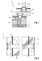
- FIG. 1 and 2 illustrated device 1 according to the invention is used for drying sewage sludge 2, which can be applied to a bottom plate of the device 1, which is referred to here as a dry surface 3.
- the dry surface 3 forming bottom plate is provided with heating pipes 4.
- the device 1 For conveying the sewage sludge 2 and distributing it to the drying surface 3, the device 1 has a conveyor 5, which in the exemplary embodiment is designed as a circulating endless conveyor.
- the conveyor 5 has a number of rectangular tubes as traverses 6, which are located above the drying surface 3 and extend across the drying surface 3.
- the trusses 6 are guided with rollers 7 on rails that form guides 8 of the traverses 6.
- a sliding guide with runners or the like can be provided (not shown).
- the rails extend in a longitudinal direction of the drying surface 3, which is a conveying direction of the device 1.
- the trusses 6 are connected, for example, with chains or steel cables 9, with which they are moved.
- the traverses 6 move in a lower plane in the conveying direction over the drying surface 3 and in an upper plane back. Deflection devices for the chains or steel cables 9 and the trusses 6 at the ends of the dry surface 3 are not shown.
- the conveyor 5 can, as shown, have a plurality of traverses 6, in principle a traverse 6. In FIG. 2 only a lower cross member 6 is drawn, which is moved in the conveying direction.
- the trusses 6 can be moved continuously or occasionally.
- the conveyor elements 10 form.
- the conveying elements 10 end over the drying surface 3, they do not streak.
- the conveyor elements 10 are upwards.
- a reversing operation in which the trusses 6 are moved not only in the conveying direction, but back and forth on the dry surface 3, possibly even only back and forth over part of a length of the dry surface 3. So that the sewage sludge 2 is conveyed in a reversing operation from one to the other end of the drying surface 3, the trusses 6 are lifted during the return movement (not shown).
- the conveying elements 10 In the lateral direction, ie in the longitudinal direction of the trusses 6 and transversely to the conveying direction, the conveying elements 10 at equal distances from each other. In the exemplary embodiment, they are arranged on an imaginary zig-zag line, ie the conveying elements 10 are arranged alternately near a front and a rear side of the trusses 6. However, this is not mandatory for the invention, the conveying elements 10 may also be arranged side by side on an imaginary straight line.
- scraper 11 From the dry surface are scraper 11 from above, which ends at a distance below the trusses 6.
- the scrapers are 11 U-shaped spring clips made of steel, with the "U” is upside down, a closed side of the "U” is located above.
- the strippers 11 forming the spring clip have a yoke which extends horizontally below the trusses 6 in the conveying direction. From the yoke two legs of the U-shaped spring clip protrude vertically downwards, with a forward leg in the conveying direction ends above the drying surface 3. The other leg merges into a coil spring and continues at the other end with a horizontal and fixed in the dry surface 3 leg.
- the two vertical legs of the U-shaped spring clip which form the scrapers 11, are in succession.
- the two vertical legs and thus the spring clip are higher than the horizontal yoke is long.
- the wipers 11 deviate from the conveyor elements 10 when the conveyor elements 10 do not reach their intended movement between the wipers 11, but instead to push against them. Wear is reduced and damage is avoided.
- FIGS. 3 and 4 are the scrapers 11 plates, which are aligned in the conveying direction of the device 1 according to the invention of the drying surface 3 vertically upwards and end under the trusses 6. Moreover, both devices 1 are the same.
- the scrapers 11 extend in the longitudinal direction of the drying surface 3, ie in the conveying direction. Their lateral distance from each other is greater than, for example, at least twice as large as a diameter of the conveyor elements 10 and the scrapers 11 are arranged between the conveyor elements 10, ie such that upon movement of the trusses 6, the conveyor elements 10 pass between the scrapers 11.
- the scrapers 11 are offset in the conveying direction to each other, from one side of the drying surface 3 to the other side always in the same direction.
- the plate-shaped scrapers 11 are arranged on an imaginary straight line, which runs obliquely to the conveying direction.
- the scrapers 11 extending in the conveying direction guide the conveying elements 10 in the conveying direction when the conveying elements 10 are located between the scrapers 11.
- the offset of the plate-shaped scrapers 11 in the conveying direction and their length are chosen so that always at least one conveying element 10, preferably two to three conveying elements 10, are located between the scrapers 11 and thereby the cross member 6 and the traverse 6 lead the other conveyor elements 10 when the next conveyor element 10 enters between the scrapers 11.
- the first conveying element 10, which enters between the scrapers 11, is located at one end of the traverse 6 on one side of the drying surface 3, where the traverse 6 is guided with the rail 8 forming the guide.
- the conveyor element 10 is guided with a small tolerance, so that it does not bounce against one of the plate-shaped scraper 11. If, nevertheless, a delivery element 10 strikes against a scraper 11, this deviates if it is designed as a spring clip or in another way resilient or movable, whereby, as already stated, reduces wear and damage is avoided.
- the scrapers 11 have a multiple, for example, three to five times the length of the diameter of the conveyor elements 10 formed as pins.
- the scrapers 11 reliably shred sewage sludge lumps to a maximum size, which is determined above all by the spacing of the scrapers 11 from one another, but also by the conveying elements 10.
- the plates Due to their extent in the conveying direction, the plates have a scraper 11 in the conveying direction sufficiently long friction surface to clean the conveying elements 10 of adhering sewage sludge. They do not necessarily clean the conveyor elements 10 completely from the Klärstamm, but sufficiently.
- the spring clips as scrapers 11, the vertical legs, which are arranged one behind the other in the conveying direction, effect a good stripping and comminution effect better than isolated pins.
- the conveying elements 10 move through the sewage sludge 2. They move the sewage sludge 2 a little way in the conveying direction, distribute the sewage sludge 2 - not necessarily evenly 3 and turn and loosen the sewage sludge.
- the trusses 6 can be moved continuously, provided is a movement from time to time.
Landscapes
- Engineering & Computer Science (AREA)
- Mechanical Engineering (AREA)
- Life Sciences & Earth Sciences (AREA)
- Hydrology & Water Resources (AREA)
- Environmental & Geological Engineering (AREA)
- Water Supply & Treatment (AREA)
- Chemical & Material Sciences (AREA)
- Organic Chemistry (AREA)
- General Engineering & Computer Science (AREA)
- Drying Of Solid Materials (AREA)
- Treatment Of Sludge (AREA)
Applications Claiming Priority (1)
| Application Number | Priority Date | Filing Date | Title |
|---|---|---|---|
| DE102012107806.8A DE102012107806A1 (de) | 2012-08-24 | 2012-08-24 | Vorrichtung zum Trocknen von insbesondere Klärschlamm |
Publications (2)
| Publication Number | Publication Date |
|---|---|
| EP2700619A1 true EP2700619A1 (fr) | 2014-02-26 |
| EP2700619B1 EP2700619B1 (fr) | 2015-01-07 |
Family
ID=48877111
Family Applications (1)
| Application Number | Title | Priority Date | Filing Date |
|---|---|---|---|
| EP13178350.8A Not-in-force EP2700619B1 (fr) | 2012-08-24 | 2013-07-29 | Dispositif de séchage notamment de boues d'épuration |
Country Status (2)
| Country | Link |
|---|---|
| EP (1) | EP2700619B1 (fr) |
| DE (1) | DE102012107806A1 (fr) |
Cited By (1)
| Publication number | Priority date | Publication date | Assignee | Title |
|---|---|---|---|---|
| CN107585999A (zh) * | 2017-10-19 | 2018-01-16 | 安徽池州瑞恩能源有限公司 | 一种搅拌式污泥烘干装置 |
Citations (2)
| Publication number | Priority date | Publication date | Assignee | Title |
|---|---|---|---|---|
| DE202008005798U1 (de) * | 2007-07-09 | 2008-07-17 | Bilfinger Berger Umwelttechnik Gmbh | Vorrichtung zum Trocknen von Schlamm |
| EP2013148B1 (fr) | 2006-05-04 | 2011-12-14 | Passavant-Geiger GmbH | Dispositif et procédé pour le séchage de boues de curage |
Family Cites Families (1)
| Publication number | Priority date | Publication date | Assignee | Title |
|---|---|---|---|---|
| CH583404A5 (fr) * | 1975-03-18 | 1976-12-31 | Patelhold Patentverwertung |
-
2012
- 2012-08-24 DE DE102012107806.8A patent/DE102012107806A1/de not_active Withdrawn
-
2013
- 2013-07-29 EP EP13178350.8A patent/EP2700619B1/fr not_active Not-in-force
Patent Citations (2)
| Publication number | Priority date | Publication date | Assignee | Title |
|---|---|---|---|---|
| EP2013148B1 (fr) | 2006-05-04 | 2011-12-14 | Passavant-Geiger GmbH | Dispositif et procédé pour le séchage de boues de curage |
| DE202008005798U1 (de) * | 2007-07-09 | 2008-07-17 | Bilfinger Berger Umwelttechnik Gmbh | Vorrichtung zum Trocknen von Schlamm |
Cited By (1)
| Publication number | Priority date | Publication date | Assignee | Title |
|---|---|---|---|---|
| CN107585999A (zh) * | 2017-10-19 | 2018-01-16 | 安徽池州瑞恩能源有限公司 | 一种搅拌式污泥烘干装置 |
Also Published As
| Publication number | Publication date |
|---|---|
| EP2700619B1 (fr) | 2015-01-07 |
| DE102012107806A1 (de) | 2014-02-27 |
Similar Documents
| Publication | Publication Date | Title |
|---|---|---|
| DE102018133070B4 (de) | Vorrichtung zum Trocknen von Klärschlamm | |
| EP3420150B1 (fr) | Dispositif de tamisage | |
| DE2047131A1 (de) | Richtungswandler fur Behalterfbr dereinnchtungen | |
| DE202012010693U1 (de) | Tunnel-Trocknungsvorrichtung für Schüttgut | |
| DE102012020044A1 (de) | Vorrichtung und Verfahren zum Trocknen von Biomasse | |
| DE69206614T2 (de) | Trenngitter. | |
| EP3095924A1 (fr) | Dispositif de séparation et d'élimination de produit à tamiser dans un liquide s'écoulant, contaminé par des produits à tamiser | |
| AT512704B1 (de) | Vorrichtung mit einer Abscheidefläche und einem beweglichen Zusatzrost zum Entfernen von Siebgut aus einer strömenden Flüssigkeit | |
| EP3066928B1 (fr) | Installation des machines de boulangerie pour convoyer de la pâte | |
| AT516456B1 (de) | Holzauftauanlage | |
| EP2013148B1 (fr) | Dispositif et procédé pour le séchage de boues de curage | |
| EP2700619B1 (fr) | Dispositif de séchage notamment de boues d'épuration | |
| DE102007032117A1 (de) | Vorrichtung zum Trocknen von Schlamm | |
| DE102015112599B4 (de) | Aufgabevorrichtung zur Aufgabe von Fördergut auf ein Förderband | |
| DE102010023249A1 (de) | Feinsiebrechen mit einer Reinigungseinrichtung zum Entfernen von Rechengut | |
| AT15559U1 (de) | Scheitholzreinigung | |
| DE3021860C2 (de) | Entmistungsförderer für Geflügel-Batterienestanlagen | |
| DE102016014448A1 (de) | Tubenfüllmaschine mit einer Tubenkörper-Übergabevorrichtung und Verfahren zur Übergabe von Tubenkörpern | |
| EP1655246B1 (fr) | Dispositif et procédure pour diviser un flot des produits à l'aide d'un glissoir | |
| DE102012011028A1 (de) | Einfüllbehälter für Formsteine mit einer Formsteinentnahmeeinrichtung | |
| DE1904578A1 (de) | Kettenfoerderer | |
| EP2123579A1 (fr) | Dispositif de déviation d'un flux de produits vrac à partir d'une trajectoire de transport | |
| EP3538455A1 (fr) | Système de transport constitué de plusieurs segments de bande transporteuse juxtaposés | |
| EP1568630B1 (fr) | Dispositif de formation de piles | |
| EP2586733A1 (fr) | Convoyeur pour transporter des pièces moulées et installation équipée d'un tel convoyeur |
Legal Events
| Date | Code | Title | Description |
|---|---|---|---|
| PUAI | Public reference made under article 153(3) epc to a published international application that has entered the european phase |
Free format text: ORIGINAL CODE: 0009012 |
|
| AK | Designated contracting states |
Kind code of ref document: A1 Designated state(s): AL AT BE BG CH CY CZ DE DK EE ES FI FR GB GR HR HU IE IS IT LI LT LU LV MC MK MT NL NO PL PT RO RS SE SI SK SM TR |
|
| AX | Request for extension of the european patent |
Extension state: BA ME |
|
| 17P | Request for examination filed |
Effective date: 20140207 |
|
| RBV | Designated contracting states (corrected) |
Designated state(s): AL AT BE BG CH CY CZ DE DK EE ES FI FR GB GR HR HU IE IS IT LI LT LU LV MC MK MT NL NO PL PT RO RS SE SI SK SM TR |
|
| GRAP | Despatch of communication of intention to grant a patent |
Free format text: ORIGINAL CODE: EPIDOSNIGR1 |
|
| INTG | Intention to grant announced |
Effective date: 20140725 |
|
| GRAS | Grant fee paid |
Free format text: ORIGINAL CODE: EPIDOSNIGR3 |
|
| GRAP | Despatch of communication of intention to grant a patent |
Free format text: ORIGINAL CODE: EPIDOSNIGR1 |
|
| INTG | Intention to grant announced |
Effective date: 20141114 |
|
| GRAA | (expected) grant |
Free format text: ORIGINAL CODE: 0009210 |
|
| AK | Designated contracting states |
Kind code of ref document: B1 Designated state(s): AL AT BE BG CH CY CZ DE DK EE ES FI FR GB GR HR HU IE IS IT LI LT LU LV MC MK MT NL NO PL PT RO RS SE SI SK SM TR |
|
| REG | Reference to a national code |
Ref country code: GB Ref legal event code: FG4D Free format text: NOT ENGLISH |
|
| REG | Reference to a national code |
Ref country code: CH Ref legal event code: EP |
|
| REG | Reference to a national code |
Ref country code: IE Ref legal event code: FG4D Free format text: LANGUAGE OF EP DOCUMENT: GERMAN |
|
| REG | Reference to a national code |
Ref country code: AT Ref legal event code: REF Ref document number: 705570 Country of ref document: AT Kind code of ref document: T Effective date: 20150215 |
|
| REG | Reference to a national code |
Ref country code: DE Ref legal event code: R096 Ref document number: 502013000289 Country of ref document: DE Effective date: 20150226 |
|
| REG | Reference to a national code |
Ref country code: NL Ref legal event code: VDEP Effective date: 20150107 |
|
| REG | Reference to a national code |
Ref country code: LT Ref legal event code: MG4D |
|
| PG25 | Lapsed in a contracting state [announced via postgrant information from national office to epo] |
Ref country code: HR Free format text: LAPSE BECAUSE OF FAILURE TO SUBMIT A TRANSLATION OF THE DESCRIPTION OR TO PAY THE FEE WITHIN THE PRESCRIBED TIME-LIMIT Effective date: 20150107 Ref country code: BG Free format text: LAPSE BECAUSE OF FAILURE TO SUBMIT A TRANSLATION OF THE DESCRIPTION OR TO PAY THE FEE WITHIN THE PRESCRIBED TIME-LIMIT Effective date: 20150407 Ref country code: NO Free format text: LAPSE BECAUSE OF FAILURE TO SUBMIT A TRANSLATION OF THE DESCRIPTION OR TO PAY THE FEE WITHIN THE PRESCRIBED TIME-LIMIT Effective date: 20150407 Ref country code: LT Free format text: LAPSE BECAUSE OF FAILURE TO SUBMIT A TRANSLATION OF THE DESCRIPTION OR TO PAY THE FEE WITHIN THE PRESCRIBED TIME-LIMIT Effective date: 20150107 Ref country code: SE Free format text: LAPSE BECAUSE OF FAILURE TO SUBMIT A TRANSLATION OF THE DESCRIPTION OR TO PAY THE FEE WITHIN THE PRESCRIBED TIME-LIMIT Effective date: 20150107 Ref country code: FI Free format text: LAPSE BECAUSE OF FAILURE TO SUBMIT A TRANSLATION OF THE DESCRIPTION OR TO PAY THE FEE WITHIN THE PRESCRIBED TIME-LIMIT Effective date: 20150107 Ref country code: ES Free format text: LAPSE BECAUSE OF FAILURE TO SUBMIT A TRANSLATION OF THE DESCRIPTION OR TO PAY THE FEE WITHIN THE PRESCRIBED TIME-LIMIT Effective date: 20150107 |
|
| PG25 | Lapsed in a contracting state [announced via postgrant information from national office to epo] |
Ref country code: PL Free format text: LAPSE BECAUSE OF FAILURE TO SUBMIT A TRANSLATION OF THE DESCRIPTION OR TO PAY THE FEE WITHIN THE PRESCRIBED TIME-LIMIT Effective date: 20150107 Ref country code: LV Free format text: LAPSE BECAUSE OF FAILURE TO SUBMIT A TRANSLATION OF THE DESCRIPTION OR TO PAY THE FEE WITHIN THE PRESCRIBED TIME-LIMIT Effective date: 20150107 Ref country code: IS Free format text: LAPSE BECAUSE OF FAILURE TO SUBMIT A TRANSLATION OF THE DESCRIPTION OR TO PAY THE FEE WITHIN THE PRESCRIBED TIME-LIMIT Effective date: 20150507 Ref country code: GR Free format text: LAPSE BECAUSE OF FAILURE TO SUBMIT A TRANSLATION OF THE DESCRIPTION OR TO PAY THE FEE WITHIN THE PRESCRIBED TIME-LIMIT Effective date: 20150408 Ref country code: NL Free format text: LAPSE BECAUSE OF FAILURE TO SUBMIT A TRANSLATION OF THE DESCRIPTION OR TO PAY THE FEE WITHIN THE PRESCRIBED TIME-LIMIT Effective date: 20150107 Ref country code: RS Free format text: LAPSE BECAUSE OF FAILURE TO SUBMIT A TRANSLATION OF THE DESCRIPTION OR TO PAY THE FEE WITHIN THE PRESCRIBED TIME-LIMIT Effective date: 20150107 |
|
| REG | Reference to a national code |
Ref country code: DE Ref legal event code: R097 Ref document number: 502013000289 Country of ref document: DE |
|
| PG25 | Lapsed in a contracting state [announced via postgrant information from national office to epo] |
Ref country code: DK Free format text: LAPSE BECAUSE OF FAILURE TO SUBMIT A TRANSLATION OF THE DESCRIPTION OR TO PAY THE FEE WITHIN THE PRESCRIBED TIME-LIMIT Effective date: 20150107 Ref country code: RO Free format text: LAPSE BECAUSE OF FAILURE TO SUBMIT A TRANSLATION OF THE DESCRIPTION OR TO PAY THE FEE WITHIN THE PRESCRIBED TIME-LIMIT Effective date: 20150107 Ref country code: EE Free format text: LAPSE BECAUSE OF FAILURE TO SUBMIT A TRANSLATION OF THE DESCRIPTION OR TO PAY THE FEE WITHIN THE PRESCRIBED TIME-LIMIT Effective date: 20150107 Ref country code: CZ Free format text: LAPSE BECAUSE OF FAILURE TO SUBMIT A TRANSLATION OF THE DESCRIPTION OR TO PAY THE FEE WITHIN THE PRESCRIBED TIME-LIMIT Effective date: 20150107 Ref country code: SK Free format text: LAPSE BECAUSE OF FAILURE TO SUBMIT A TRANSLATION OF THE DESCRIPTION OR TO PAY THE FEE WITHIN THE PRESCRIBED TIME-LIMIT Effective date: 20150107 |
|
| PLBE | No opposition filed within time limit |
Free format text: ORIGINAL CODE: 0009261 |
|
| STAA | Information on the status of an ep patent application or granted ep patent |
Free format text: STATUS: NO OPPOSITION FILED WITHIN TIME LIMIT |
|
| 26N | No opposition filed |
Effective date: 20151008 |
|
| PG25 | Lapsed in a contracting state [announced via postgrant information from national office to epo] |
Ref country code: IT Free format text: LAPSE BECAUSE OF FAILURE TO SUBMIT A TRANSLATION OF THE DESCRIPTION OR TO PAY THE FEE WITHIN THE PRESCRIBED TIME-LIMIT Effective date: 20150107 |
|
| REG | Reference to a national code |
Ref country code: DE Ref legal event code: R119 Ref document number: 502013000289 Country of ref document: DE |
|
| PG25 | Lapsed in a contracting state [announced via postgrant information from national office to epo] |
Ref country code: MC Free format text: LAPSE BECAUSE OF FAILURE TO SUBMIT A TRANSLATION OF THE DESCRIPTION OR TO PAY THE FEE WITHIN THE PRESCRIBED TIME-LIMIT Effective date: 20150107 Ref country code: SI Free format text: LAPSE BECAUSE OF FAILURE TO SUBMIT A TRANSLATION OF THE DESCRIPTION OR TO PAY THE FEE WITHIN THE PRESCRIBED TIME-LIMIT Effective date: 20150107 |
|
| PG25 | Lapsed in a contracting state [announced via postgrant information from national office to epo] |
Ref country code: LU Free format text: LAPSE BECAUSE OF FAILURE TO SUBMIT A TRANSLATION OF THE DESCRIPTION OR TO PAY THE FEE WITHIN THE PRESCRIBED TIME-LIMIT Effective date: 20150729 |
|
| REG | Reference to a national code |
Ref country code: IE Ref legal event code: MM4A |
|
| PG25 | Lapsed in a contracting state [announced via postgrant information from national office to epo] |
Ref country code: DE Free format text: LAPSE BECAUSE OF NON-PAYMENT OF DUE FEES Effective date: 20160202 |
|
| REG | Reference to a national code |
Ref country code: FR Ref legal event code: ST Effective date: 20160331 |
|
| PG25 | Lapsed in a contracting state [announced via postgrant information from national office to epo] |
Ref country code: FR Free format text: LAPSE BECAUSE OF NON-PAYMENT OF DUE FEES Effective date: 20150731 |
|
| PG25 | Lapsed in a contracting state [announced via postgrant information from national office to epo] |
Ref country code: IE Free format text: LAPSE BECAUSE OF NON-PAYMENT OF DUE FEES Effective date: 20150729 |
|
| REG | Reference to a national code |
Ref country code: CH Ref legal event code: PL |
|
| PG25 | Lapsed in a contracting state [announced via postgrant information from national office to epo] |
Ref country code: MT Free format text: LAPSE BECAUSE OF FAILURE TO SUBMIT A TRANSLATION OF THE DESCRIPTION OR TO PAY THE FEE WITHIN THE PRESCRIBED TIME-LIMIT Effective date: 20150107 |
|
| PG25 | Lapsed in a contracting state [announced via postgrant information from national office to epo] |
Ref country code: LI Free format text: LAPSE BECAUSE OF NON-PAYMENT OF DUE FEES Effective date: 20160731 Ref country code: CH Free format text: LAPSE BECAUSE OF NON-PAYMENT OF DUE FEES Effective date: 20160731 |
|
| PG25 | Lapsed in a contracting state [announced via postgrant information from national office to epo] |
Ref country code: HU Free format text: LAPSE BECAUSE OF FAILURE TO SUBMIT A TRANSLATION OF THE DESCRIPTION OR TO PAY THE FEE WITHIN THE PRESCRIBED TIME-LIMIT; INVALID AB INITIO Effective date: 20130729 |
|
| PG25 | Lapsed in a contracting state [announced via postgrant information from national office to epo] |
Ref country code: CY Free format text: LAPSE BECAUSE OF FAILURE TO SUBMIT A TRANSLATION OF THE DESCRIPTION OR TO PAY THE FEE WITHIN THE PRESCRIBED TIME-LIMIT Effective date: 20150107 |
|
| PG25 | Lapsed in a contracting state [announced via postgrant information from national office to epo] |
Ref country code: BE Free format text: LAPSE BECAUSE OF NON-PAYMENT OF DUE FEES Effective date: 20150731 |
|
| GBPC | Gb: european patent ceased through non-payment of renewal fee |
Effective date: 20170729 |
|
| PG25 | Lapsed in a contracting state [announced via postgrant information from national office to epo] |
Ref country code: GB Free format text: LAPSE BECAUSE OF NON-PAYMENT OF DUE FEES Effective date: 20170729 |
|
| PG25 | Lapsed in a contracting state [announced via postgrant information from national office to epo] |
Ref country code: SM Free format text: LAPSE BECAUSE OF FAILURE TO SUBMIT A TRANSLATION OF THE DESCRIPTION OR TO PAY THE FEE WITHIN THE PRESCRIBED TIME-LIMIT Effective date: 20150107 |
|
| PG25 | Lapsed in a contracting state [announced via postgrant information from national office to epo] |
Ref country code: PT Free format text: LAPSE BECAUSE OF FAILURE TO SUBMIT A TRANSLATION OF THE DESCRIPTION OR TO PAY THE FEE WITHIN THE PRESCRIBED TIME-LIMIT Effective date: 20150107 Ref country code: TR Free format text: LAPSE BECAUSE OF FAILURE TO SUBMIT A TRANSLATION OF THE DESCRIPTION OR TO PAY THE FEE WITHIN THE PRESCRIBED TIME-LIMIT Effective date: 20150107 Ref country code: MK Free format text: LAPSE BECAUSE OF FAILURE TO SUBMIT A TRANSLATION OF THE DESCRIPTION OR TO PAY THE FEE WITHIN THE PRESCRIBED TIME-LIMIT Effective date: 20150107 |
|
| PG25 | Lapsed in a contracting state [announced via postgrant information from national office to epo] |
Ref country code: AL Free format text: LAPSE BECAUSE OF FAILURE TO SUBMIT A TRANSLATION OF THE DESCRIPTION OR TO PAY THE FEE WITHIN THE PRESCRIBED TIME-LIMIT Effective date: 20150107 |
|
| REG | Reference to a national code |
Ref country code: AT Ref legal event code: MM01 Ref document number: 705570 Country of ref document: AT Kind code of ref document: T Effective date: 20180729 |
|
| PG25 | Lapsed in a contracting state [announced via postgrant information from national office to epo] |
Ref country code: AT Free format text: LAPSE BECAUSE OF NON-PAYMENT OF DUE FEES Effective date: 20180729 |