EP2700706B1 - Homogénéisateur - Google Patents
Homogénéisateur Download PDFInfo
- Publication number
- EP2700706B1 EP2700706B1 EP13180841.2A EP13180841A EP2700706B1 EP 2700706 B1 EP2700706 B1 EP 2700706B1 EP 13180841 A EP13180841 A EP 13180841A EP 2700706 B1 EP2700706 B1 EP 2700706B1
- Authority
- EP
- European Patent Office
- Prior art keywords
- blender
- crushing
- tissue sample
- homogenizer
- crushing part
- Prior art date
- Legal status (The legal status is an assumption and is not a legal conclusion. Google has not performed a legal analysis and makes no representation as to the accuracy of the status listed.)
- Active
Links
Images






Classifications
-
- G—PHYSICS
- G01—MEASURING; TESTING
- G01N—INVESTIGATING OR ANALYSING MATERIALS BY DETERMINING THEIR CHEMICAL OR PHYSICAL PROPERTIES
- G01N1/00—Sampling; Preparing specimens for investigation
- G01N1/28—Preparing specimens for investigation including physical details of (bio-)chemical methods covered elsewhere, e.g. G01N33/50, C12Q
-
- C—CHEMISTRY; METALLURGY
- C12—BIOCHEMISTRY; BEER; SPIRITS; WINE; VINEGAR; MICROBIOLOGY; ENZYMOLOGY; MUTATION OR GENETIC ENGINEERING
- C12M—APPARATUS FOR ENZYMOLOGY OR MICROBIOLOGY; APPARATUS FOR CULTURING MICROORGANISMS FOR PRODUCING BIOMASS, FOR GROWING CELLS OR FOR OBTAINING FERMENTATION OR METABOLIC PRODUCTS, i.e. BIOREACTORS OR FERMENTERS
- C12M45/00—Means for pre-treatment of biological substances
- C12M45/02—Means for pre-treatment of biological substances by mechanical forces; Stirring; Trituration; Comminuting
-
- G—PHYSICS
- G01—MEASURING; TESTING
- G01N—INVESTIGATING OR ANALYSING MATERIALS BY DETERMINING THEIR CHEMICAL OR PHYSICAL PROPERTIES
- G01N1/00—Sampling; Preparing specimens for investigation
- G01N1/28—Preparing specimens for investigation including physical details of (bio-)chemical methods covered elsewhere, e.g. G01N33/50, C12Q
- G01N1/286—Preparing specimens for investigation including physical details of (bio-)chemical methods covered elsewhere, e.g. G01N33/50, C12Q involving mechanical work, e.g. chopping, disintegrating, compacting, homogenising
Definitions
- the present invention relates to a homogenizer for crushing tissue samples collected from human beings, animals, or plants.
- a genetic test is a test that examines, for clinical purposes, whether there is a mutation or karyotype that is relevant to a genetic disease by analyzing nucleic acids or chromosomes.
- Examples of a genetic test include a test that determines whether there is a nucleic acid derived from cancer cells in a tissue sample resected from an organism.
- the test process includes three major process steps of preprocessing, nucleic acid amplification, and detection.
- a crushing process to crush (homogenize) a tissue sample is performed.
- a crushing method in which a crushing tool called a blender is brought, while being rotated, into contact with a tissue sample.
- US Patent No. 8216528 discloses a sample processing device which crushes a tissue sample by the above crushing method.
- the sample processing device disclosed in US Patent No. 8216528 includes a crushing tool composed of an inner crushing member and an outer side crushing member which is a tubular body capable of housing the inner crushing member therein.
- the sample processing device is configured such that a tissue sample (lymph node) is crushed to a predetermined size, by the inner crushing member of the crushing tool being repeatedly moved upward and downward while being rotated by a motor.
- WO 2005/047866 A1 is concerned with a sample homogenizer.
- An object of the present invention is to provide a homogenizer that can suppress occurrence of a crushing failure of the tissue sample and can promote crushing of the tissue sample, compared with conventional homogenizers.
- a homogenizer according to an aspect of the present invention is a homogenizer as defined in claim 1.
- the homogenizer when crushing a tissue sample by rotating the blender, an excessive pressing force from the blender applied to the tissue sample can be absorbed.
- an excessive pressing force from the blender applied to the tissue sample can be absorbed.
- crushing of the tissue sample can be promoted.
- the absorbing means includes an elastic member that contracts when the blender is pressed against the tissue sample in the container.
- the absorbing means can be configured in a simple manner.
- the homogenizer further comprises a support part supporting the crushing part and a second driver configured to move the support part in a direction to insert the crushing part into the container.
- the crushing part can be inserted into the container.
- the crushing part is attached, via the elastic member, to the support part so as to be movable relative to the support part, and the elastic member may be provided between the support part and the crushing part so as to contract when the crushing part moves relative to the support part.
- the absorbing means may absorb a pressure such that the pressure applied from the blender to the tissue sample does not exceed a predetermined magnitude.
- the second driver is configured so as to reciprocate the support part in the direction and in an opposite direction thereof.
- the homogenizer may further comprise a controlling means for controlling an operation of homogenizer, and characterized in that the controlling means controls the second driver such that the blender reciprocates in the container with maintaining the blender to be rotated.
- the controlling means may be configured to control the second driver to move the crushing part in the opposite direction, and to control the rotation driver to rotate the blender at a position away from the tissue sample in the container when crushing of the tissue sample by the blender is terminated.
- the homogenizer may further comprise a container holder including a plurality of holders each capable of holding a container, and may be characterized in that a pair of the crushing part and the rotation driver is provided for each of the plurality of holders, and the absorbing means is provided for each of the plurality of the crushing parts.
- a pressing force applied by each of the plurality of the crushing parts to a tissue sample can be independently adjusted in accordance with hardness of each tissue sample.
- the blender may have an inner blade and an outer blade, and the rotation driver rotates either one of the inner blade and the outer blade relative to the other.
- the tissue sample can be efficiently crushed by using the two blades.
- the homogenizer may further comprise a controlling means for controlling an operation of the homogenizer; and a detecting means for detecting the number of rotations of the blender, and may be characterized in that the controlling means controls the rotation driver to stop rotation of the blender when the number of the rotations is outside a predetermined range.
- the homogenizer may further comprises a container holder including a plurality of holders each capable of holding a container, and may be characterized in that a plurality of pairs of the crushing part and the rotation driver are provided so as to correspond to the container holder, and in a case where the number of rotations of a blender driven by one of the rotation drivers is outside the predetermined range, the controlling means stops the rotation driver and causes the other rotation drivers to continue driving.
- the homogenizer may further comprise a notification means for making a notification of an abnormality, and characterized in that in a case where the number of rotations of the blender is smaller than a lower limit value of the predetermined range, the controlling means causes the blender to continue rotating and controls the notification means to output a notification of an abnormality after completion of the rotation.
- the homogenizer may be characterized in that the blender is attached at a tip end of the crushing part in a longitudinal direction and is biased toward its tip end by the absorbing means, and the crushing part is configured to contract when a force exceeding a tension of the bias is applied to the crushing part in an opposite direction to a moving direction of the crushing part, while the force is absorbed by the absorbing means.
- the blender may be detachably attached to a body of the crushing part.
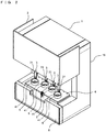
- FIG. 1 is a perspective view showing an outer view of a homogenizer according to the present embodiment.
- a homogenizer 1 according to the present embodiment is an apparatus that is installed mainly in a pathological laboratory of a hospital and that is configured to crush, in a buffer solution, a tissue sample collected from a patient in an operating room.
- the homogenizer 1 includes an apparatus body 10 having a substantially rectangular parallelepiped shape, and a cool box 4 (see FIG. 2 ) detachable from the apparatus body 10.
- the apparatus body 10 is provided with a cover 2 which covers a part of the front face thereof.
- the cover 2 is slidable in the up-down direction so as to be able to be opened and closed.
- FIG. 1 shows a state where the cover 2 is closed.
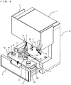
- FIG. 2 is a perspective view showing an outer view of the apparatus body 10 with the cover 2 open.
- a middle portion in the up-down direction of the apparatus body 10 is exposed.
- This middle portion has a shape whose front side is recessed.
- four crushing parts 3 are provided.
- Each crushing part 3 includes a rotation mechanism section provided in the ceiling portion for the recess, and a blender 31 which is a crushing tool for crushing a tissue sample.
- Each blender 31 is detachable from the rotation mechanism section and disposable, in order to prevent contamination.
- FIG. 3 is a fragmentary side sectional view showing a structure of a blender 31.
- the blender 31 has a double structure, and includes an inner part 31a and an outer part 31b, each having a cylindrical shape.
- the lower ends of the inner part 31a and the outer part 31b are provided with blades 31p and 31q for crushing a tissue sample, respectively.
- the rotation mechanism section has built therein a blade rotating motor 32 being a brushless DC motor (see FIG. 8 ).
- the blade 31p (hereinafter, referred to as “inner blade”) of the inner part 31a and the blade 31 q (hereinafter, referred to as “outer blade”) of the outer part 31b are rotated coaxially relative to each other, whereby the tissue sample which is brought into contact with the inner blade 31p and the outer blade 31q is cut.
- the cool box 4 is capable of holding four sample containers 5. Each sample container 5 contains a buffer and a tissue sample collected from a subject. At positions on the upper surface of the cool box 4 and immediately below the crushing parts 3, four openings 41 are provided, respectively.
- the apparatus body 10 includes a blade raising/lowering motor 33 (see FIG. 8 ) being a brushless DC motor. When the blade raising/lowering motor 33 is driven, the crushing parts 3 are raised/lowered. When the crushing parts 3 are lowered due to the blade raising/lowering motor 33, the blenders 31 are inserted into the openings 41 respectively.
- FIG. 4 is a fragmentary side sectional view of a blender 31 for describing crushing of a tissue sample performed by the blender 31.
- the tip of the blender 31 is lowered to the vicinity of a bottom portion of the sample container 5.
- the tissue sample in the sample container 5 is crushed.
- FIG. 5 is a perspective view showing a state where the lower part of the apparatus body 10 is drawn out.
- the lower part of the apparatus body 10 serves as a setting part 6 in which a user sets the cool box 4.
- the setting part 6 is slidable by means of a rail in the front-rear direction.
- the cool box 4 has a rectangular parallelepiped shape which is long in the substantially left-right direction.
- the cool box 4 includes handles 42 at respective side ends thereof.
- the setting part 6 is provided with a mounting part 61 on which to mount the cool box 4.
- the mounting part 61 has a quadrangle-dish-like shape slightly larger than the bottom portion of the cool box 4. On the mounting part 61, the cool box 4 can be mounted.
- the cool box 4 has a rectangular parallelepiped box shape. On the upper surface of the cool box 4, the four openings 41 are provided. Outer two openings 41 are arranged further forward than inner two openings 41. That is, the inner two openings 41 are arranged side by side along the left-right direction, and the rightmost opening 41 and the leftmost opening 41 are arranged at positions further forward than those of the inner two openings 41.
- the cool box 4 is configured to hold therein crushed ice (ice crushed into particles having diameter of about 1 mm to 1 cm) as a refrigerant, and four sample containers 5 can be held in the cool box 4 as described above. Accordingly, the tissue sample and the lysate inside the sample containers 5 can be kept cool in the cool box 4.
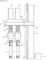
- FIG. 6 is a side view showing the structure of the crushing part 3.
- the crushing part 3 includes a rotation mechanism section 38 and the blender 31 detachable to the lower end of the rotation mechanism section 38.
- the blade rotating motor 32 is provided at the upper end of the rotation mechanism section 38.
- the blade rotating motor 32 By the blade rotating motor 32 being driven, the inner blade 31p of the blender 31 connected to the rotation mechanism section 38 is rotated.
- the four crushing parts 3 are supported by one plate-like support part 30.
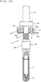
- FIG. 7A is a fragmentary side sectional view showing the structure of the crushing part 3.
- the rotation mechanism section 38 includes a shaft part 34 having a cylindrical shape.
- the support part 30 is provided with four support blocks 36 each having an annular shape.
- a hole 36a is provided in a center portion of each support block 36, and the shaft parts 34 pass through these holes 36a, respectively.
- the diameter of the shaft part 34 is slightly smaller than the diameter of the hole 36a, which allows the rotation mechanism section 38 to move in the up-down direction relative to the support part 30.
- a stopper 35 having a disk-like shape is provided below the blade rotating motor 32.
- the shaft part 34 described above is provided so as to extend downward from this stopper 35.
- the stopper 35 is arranged on the upper side of the support block 36.
- the support block 36 is provided with another hole 36b passing therethrough in the up-down direction, and a guide pin 37 extended downward from the lower surface of the stopper 35 is inserted into this hole 36b. Accordingly, the crushing part 3 is prevented from rotating relative to the support part 30.
- a spring 39 is wound around the shaft part 34.
- an attachment part 34a having a diameter larger than that of the shaft part 34 is provided below the shaft part 34.
- the attachment part 34a is configured such that the blender 31 is detachable from the attachment part 34a.
- the upper end of the spring 39 abuts against the lower surface of the support part 30, and the lower end of the spring 39 abuts against the upper end surface of the attachment part 34a.
- the spring 39 biases the attachment part 34a in the lower side. Accordingly, when the blender 31 is attached to the attachment part 34, the blender 31 is biased to the side of its tip end.
- the apparatus body 10 includes a raising/lowering mechanism section 18 (see Fig. 6 ) which moves the support part 30 in the up-down direction.
- the raising/lowering mechanism section 18 is provided on the side opposite to the crushing parts 3 relative to a wall part 19 of the apparatus body 10, that is, the raising/lowering mechanism section 18 is provided at the rear of the wall part 19.
- the raising/lowering mechanism section 18 includes a belt and a pulley which is driven by the blade raising/lowering motor 33.
- a coupling member 30a is extended to the rear of the support part 30.
- the coupling member 30a is connected to the raising/lowering mechanism section 18 through an opening that is long in the up-down direction provided in the wall part 19.
- the support part 30 is coupled to the raising/lowering mechanism section 18 via the coupling member 30a.
- the blade raising/lowering motor 33 being driven, the support part 30 can be moved in the up-down direction.
- a rail 20 being a direct-acting guide is attached to the wall part 19, and a moving element 20a of the direct-acting guide movable along the rail is attached to the support part 30. Accordingly, movement of the support part 30 in the up-down direction is guided.
- the four crushing parts 3 supported by the support part 30 are also moved in the up-down direction, along with the support part 30. Therefore, when the support part 30 is moved downward from a state where the crushing parts 3 are located above the sample containers 5, the blenders 31 are inserted into the sample containers 5, the blade tips of the blenders 31 are pressed against the tissue samples, and then the tissue samples are crushed, respectively.
- FIG. 7A shows a state where the crushing part 3 is at the lowest position relative to the support part 30.
- the compression spring 39 is applying a force in directions in which the support part 30 and the attachment part 34a are repelled from each other, whereby the lower surface of the stopper 35 is pressed against the upper surface of the support block 36. Accordingly, the crushing part 3 is as a whole biased to expand in longitudinal direction.
- FIG. 7B is a fragmentary side sectional view of the crushing part 3 showing a state where the crushing part 3 has been moved upward relative to the support part 30.
- the spring 39 is compressed and the shaft part 34 slides inside the hole 36a of the support block 36, whereby the stopper 35 is separated from the support block 36.
- F k ⁇ T.
- k is the spring constant of the spring 39. That is, by the distance T in proportion to the pressing force F applied to the blender 31, the spring 39 is compressed and the crushing part 3 is moved upward.
- the blender 31 comes into contact with the tissue sample 91 contained in the sample container 5. Then further the crushing part 3 is lowered.
- the tissue sample is soft, the tissue sample 91 deforms by being pressed by the blender 31. Accordingly, the blade tip of the blender 31 deeply bites into the tissue sample 91 without the crushing part 3 being moved upward relative to the support part 30, and the tissue sample 91 is crushed by rotation of the inner blade 31p of the blender 31.
- the spring constant k of the spring 39 is set so as not to be excessive such that the pressing force F does not impede the rotation of the blender 31.
- a pressure applied to the tissue sample caused by lowering the blender 31 is absorbed by the spring 39. This can avoid the situation where the blender 31 is strongly pressed to the tissue sample and stuck with the tissue sample.
- the blender 31 is pressed against the tissue sample 92 with the pressing force F, the rotation of the inner blade 31p is maintained. Accordingly, crushing of the tissue sample 92 is promoted and the tissue sample 92 is assuredly crushed.
- FIG. 8 is a block diagram showing a configuration of an electric circuit of the homogenizer 1 according to the present embodiment.
- the apparatus body 10 of the homogenizer 1 includes a controller 7 implemented by an FPGA. To the controller 7, the blade rotating motors 32 and the blade raising/lowering motor 33 are connected. The controller 7 can control the blade rotating motors 32 and the blade raising/lowering motor 33. Further, the blade rotating motors 32 are respectively provided with rotation speed sensors 32a. Each rotation speed sensor 32a is configured to detect a rotation speed of a corresponding blade rotating motor 32. Each rotation speed sensor 32a is connected to the controller 7, and can output a detection signal of a rotation speed to the controller 7.
- the housing of the apparatus body 10 is provided with a cover open/close sensor 21 being a photo interrupter for detecting that the cover 2 is closed.
- the cover open/close sensor 21 is connected to the controller 7, and can output a detection signal to the controller 7.
- the apparatus body 10 is provided with a cool box mount sensor 62 being a photo interrupter for detecting that the cool box 4 is mounted on the setting part 6.
- the cool box mount sensor 62 is connected to the controller 7, and can output a detection signal to the controller 7.
- the housing of the apparatus body 10 is provided with a start switch 72 and an emergency stop switch 73.
- the start switch 72 and the emergency stop switch 73 are button switches provided on the front face of the apparatus body 10, and are operable by an operator.
- the start switch 72 and the emergency stop switch 73 are connected to the controller 7 and can provide output signals thereof to the controller 7.
- the start switch 72 is operated, the homogenizer 1 starts a crushing process.
- the emergency stop switch 73 is operated during the crushing process, the crushing process is suspended.
- the raising/lowering mechanism section 18 of the apparatus body 10 is provided with a plurality of photo interrupters for detecting positions in the up-down direction of each crushing part 3 supported by the support part 30.
- An origin sensor 14 is a photo interrupter for detecting whether each crushing part 3 is at an origin position
- a waiting position sensor 15 is a photo interrupter for detecting whether the crushing part 3 is at a waiting position.
- the origin position is a position above each sample container 5 held in the cool box 4, and is used for initial position setting of the crushing part 3 in an initialization operation for the homogenizer 1.
- the waiting position is a position lower than the origin position, and is a position for causing the crushing part 3 to wait before performing a crushing operation of the tissue sample.
- An upper position sensor 16 is a photo interrupter for detecting whether the crushing part 3 is at a second position.
- a lower position sensor 17 is a photo interrupter for detecting whether the crushing part 3 is at a first position.
- the first position is a position of the crushing part 3 where the tip of the blender 31 is located near the bottom portion of the sample container 5.
- the second position is a position higher than the first position and lower than the waiting position. In the crushing operation of a tissue sample by the blender 31, the crushing part 3 reciprocates between the first position and the second position.
- Each of the origin sensor 14, the waiting position sensor 15, the upper position sensor 16, and the lower position sensor 17 is connected to the controller 7 and can output a detection signal to the controller 7.
- LEDs 13 are attached to the wall part 19 of the apparatus body 10, in a line along the left-right direction (see FIG. 5 ). These LEDs 13 are for making notifications of abnormalities in the crushing parts 3, and respectively correspond to the crushing parts 3.
- the leftmost LED 13 is for making a notification of an abnormality in the leftmost crushing part 3.
- the LED 13 second from the left is for making a notification of an abnormality in the crushing part 3 second from the left.
- the LED 13 third from the left is for making a notification of an abnormality in the crushing part 3 third from the left.
- the rightmost LED 13 is for making a notification of an abnormality in the rightmost crushing part 3. As shown in FIG. 8 , these LEDs 13 are connected to the controller 7, and can be controlled by the controller 7.
- a buzzer BZ is provided inside the apparatus body 10 (see FIG. 8 ).
- the homogenizer 1 sounds the buzzer when the crushing process has been completed and also when an error has occurred.
- the apparatus body 10 is provided with a cover lock solenoid CS for locking the cover 2 closed.
- the cover lock solenoid CS locks the cover 2 when the start switch 72 is operated, and it unlocks the cover 2 when the crushing process is completed. Accordingly, the cover 2 is prevented from being opened during the crushing process, and thus, safety is improved.
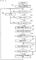
- FIG. 9 is a flow chart showing the procedure of operations performed by the homogenizer 1 according to the present embodiment.
- the controller 7 drives the blade raising/lowering motor 33 to raise/lower the crushing parts 3.
- the processing is started.
- the controller 7 controls the blade raising/lowering motor 33 to perform an initial operation (step S101).
- the initial operation the crushing parts 3 are raised first, until the origin sensor 14 is turned on.
- the origin sensor 14 is turned on
- the crushing parts 3 are lowered until the waiting position sensor 15 is turned on.
- the crushing parts 3 are raised again until the origin sensor 14 is turned on.
- the initial operation confirms that the raising/lowering operation of the crushing parts 3 can be performed normally.
- the controller 7 determines whether the start switch 72 has been turned on (step S102). When an operator turns on the start switch 72, the start switch 72 provides an output signal to the controller 7, whereby the controller 7 detects that the start switch 72 has been turned on. When the start switch 72 is not turned on (NO in step S102), the controller 7 repeats step S102.
- step S102 when it is detected that the start switch 72 has been turned on (YES in step S102), the controller 7 detects whether the cover 2 is closed (step S103). When it is not detected that the cover 2 is closed (NO in step S103), the controller 7 sounds the buzzer BZ in order to notify the operator that the cover 2 is not closed (step S105), and returns the processing to step S102. When it is detected that the cover 2 is closed in step S103 (YES in step S103), the controller 7 advances the processing to step S104.
- the controller 7 determines whether the cool box 4 is mounted (step S104). As described above, when the setting part 6 is moved toward the apparatus body 10 side with the cool box 4 mounted on the setting part 6, the cool box mount sensor 62 detects the cool box 4, and outputs a detection signal corresponding to this detection. By receiving this detection signal, the controller 7 detects that the cool box 4 is mounted on the apparatus body 10. In step S104, when it not detected that the cool box 4 is mounted (NO in step S104), the controller 7 sounds the buzzer BZ in order to notify the operator that the cool box 4 is not mounted (step S105), and returns the processing to step S102. When the cool box 4 is mounted, the controller 7 advances the processing to step S106, and performs a crush control process for driving the crushing parts 3 in order to crush the tissue samples (step S106).
- FIG. 10 is a flow chart showing the procedure of the crush control process.
- the controller 7 controls the cover lock solenoid CS to lock the cover 2 first, and then causes the crushing parts 3 to be lowered (step S201).
- the controller 7 determines whether the waiting position sensor 15 has been turned on (step S202). When the waiting position sensor 15 is off (NO in step S202), i.e., the crushing parts 3 are not at the waiting position, the controller 7 returns the processing to step S201 to continue lowering of the crushing parts 3.
- the waiting position sensor 15 is turned on in step S202 (YES in step S202), i.e., the crushing parts 3 reaches the waiting position, the controller 7 controls the blade raising/lowering motor 33 to stop lowering of the crushing parts 3 (step S203).
- the controller 7 controls the four blade rotating motors 32 respectively to start rotation of the inner blades 31p of the corresponding blenders 31 (step S204).
- the inner blades 31p of the blenders 31 rotate at a predetermined rotation speed.
- step S205 Upon the start of rotation of each crushing part 3 in step S204, the controller 7 starts a rotation monitoring process (step S205) described below.
- the rotation monitoring process (see, Fig. 11 ) is performed in parallel with the crush control process.
- the rotation monitoring process will be described later with reference to Fig. 11 . Accordingly, while monitoring whether the inner blade 31p of each blender 31 is normally rotating, the crush control process is performed.
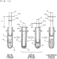
- FIG. 12 is a schematic diagram for describing the operation performed by each crushing part 3.
- the blender 31 is provided with a flange 311a having an annular shape and protruding outward.
- the outer diameter of the flange 311 a is greater than the outer diameter of the opening of the sample container 5.
- the blender 31 is held for three seconds in a state where the flange 311a is positioned at the waiting position which is higher than the upper end of the sample container 5 by a distance A.
- the tip portion of the blender 31 is located near the center portion in the longitudinal direction of the sample container 5, and is above the liquid surface of a lysate 81.
- step S207 the controller 7 determines whether the number of raising/lowering times of the crushing part 3 has reached a predetermined value. In the present embodiment, this predetermined value is 15. When the number of raising/lowering times has not reached the predetermined value (NO in step S207), the controller 7 advances the processing to step S208. In step S208, the controller 7 controls the blade raising/lowering motor 33 to lower the crushing part 3 (step S208). The crushing part 3 is lowered while the inner blade 31p of the blender 31 is rotated. The controller 7 determines whether the lower position sensor 17 has been turned on (step S209).
- step S209 When the crushing part 3 is not at the first position and the lower position sensor 17 is still off (NO in step S209), the controller 7 returns the processing to step S208 to continue lowering of the crushing part 3. On the other hand, when the crushing part 3 has reached the first position and the lower position sensor 17 has been turned on in step S209 (YES in step S209), the controller 7 controls the blade raising/lowering motor 33 to stop lowering of the crushing part 3 (step S210). Then, the controller 7 waits in that state for one second (step S211).
- the tip of the blender 31 is located near the bottom portion of the sample container 5. Accordingly, the inner blade 31p and the outer blade 31q of the blender 31 come into contact with the tissue sample 82, and by the inner blade 31p and the outer blade 31q rotating relative to each other, the tissue sample 82 is crushed.
- the flange 311a of the blender 31 abuts against the upper end of the sample container 5. That is, the opening of the sample container 5 is closed with the flange 311 a, and thus, scatter of a mixture of the tissue sample and the lysate from the sample container 5 is prevented.
- the controller 7 controls the blade raising/lowering motor 33 to raise the crushing part 3 (step S212). That is, while the inner blade 31p of the blender 31 rotating, the crushing part 3 is raised.
- the controller 7 determines whether the upper position sensor 16 has been turned on (step S213). When the crushing part 3 is not at the second position and the upper position sensor 16 is still off (NO in step S213), the controller 7 returns the processing to step S212 to continue raising of the crushing part 3.
- the controller 7 controls the blade raising/lowering motor 33 to stop raising of the crushing part 3 (step S214). Further, the controller 7 waits in that state for one second (step S215).
- the above operation is described with reference to FIG. 12 .
- the tip of the blender 31 is located above the bottom portion of the sample container 5 and below the liquid surface of the lysate. Accordingly, pieces of the crushed tissue sample and the lysate are mixed together, and thus, clogging of the tissue sample between the inner blade 31p and the outer blade 31q is prevented.
- the blender 31 is provided with a flange 311b having an annular shape, below the flange 311a.
- the outer diameter of the flange 311b is set to be slightly smaller than the inner diameter of the sample container 5.
- the flange 311b is located at the upper end of the sample container 5. That is, the opening of the sample container 5 is substantially closed with the flange 311b, and thus, scatter of a mixture of the tissue sample and the lysate from the sample container 5 is prevented.
- step S207 After waiting for one second in step S215, the controller 7 returns the processing to step S207, and determines again whether the number of raising/lowering times of the crushing part 3 has reached the predetermined value (step S207). Until the number of raising/lowering times of the crushing part 3 reaches the predetermined value (15 times), the processes of step S208 to S215 are repeated.
- step S207 the controller 7 ends the rotation monitoring process being performed in parallel with the crush control process (step S216), controls the blade rotating motors 32 to stop rotation of the inner blades 31p of the blenders 31 (step S217), and then returns the processing to the main routine.
- FIG. 13 is a graph for describing raising/lowering of the crushing part 3 in the crushing operation.
- the vertical axis represents position of the blender 31, and the horizontal axis represents time.
- the blender 31 is held at the first position being the lowest point for about one second, and then is moved to the second position, which is higher than the first position by a distance B.
- the blender 31 is held at the second position being the highest point for about one second, and then is lowered to the first position.
- such raising/lowering of the crushing part 3 is repeated a predetermined times (15 times). During this time, the inner blade 31p of the blender 31 continues to rotate. Such a crushing operation is performed for 60 seconds.
- each blender 31 performs the rotating operation while reciprocating between the first position and the second position as described above.
- the inner blade 31p and the outer blade 31q of the blender 31 do not stay at a certain position, and accordingly, the mixture of the tissue sample and the lysate is stirred well. Further, pieces of the tissue sample are prevented from being attached to the inner wall of the sample container 5 and held there, and thus, the size of the pieces of the crushed tissue sample becomes uniform.
- the crushing part 3 When the crushing part 3 is at the first position and the inner blade 31p of the blender 31 rotates while being pressed against the tissue sample, there may be a case where the inner blade 31p is stuck to the tissue sample. If the inner blade 31p is stuck to the tissue sample, not only the inner blade 31p but also the tissue sample rotate in an integrated manner. This may cause a crushing failure.
- raising/lowering of the crushing part 3 As described above, when the crushing part 3 is lowered, the blender 31 is pressed against the tissue sample, and when the crushing part 3 is raised, the blender 31 is separated from the tissue sample.
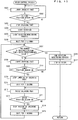
- FIG. 11 is a flow chart showing the procedure of the rotation monitoring process.
- the rotation monitoring process is a process for monitoring that rotation of each crushing part in the crush control process is normally being performed. This process is performed in parallel with the crush control process. It should be noted that the rotation monitoring process is individually performed for each of the four blade rotating motors 32.
- the controller 7 has four rotation abnormality flags in an area of a memory included therein. The rotation abnormality flags respectively correspond to the blade rotating motors 32. The flags are used for storing information indicating presence/absence of an abnormality in their corresponding blade rotating motors 32. Each rotation abnormality flag is set to OFF, as an initial value, which indicates that there is no abnormality. When an abnormality in a corresponding blade rotating motor 32 has been detected, the rotation abnormality flag is set to ON, which indicates that an abnormality has occurred.
- the controller 7 determines, based on an output signal from each rotation speed sensor 32a, whether the rotation speed of its corresponding blade rotating motor 32 is less than or equal to a first reference value (step S301).
- the first reference value is 9500 rotations/second in the present embodiment.
- the controller 7 determines that an abnormality has occurred in the blade rotating motor 32.
- the controller sets the rotation abnormality flag corresponding to this blade rotating motor to ON (step S302), and returns the processing to step S301.
- step S303 determines, based on the output signal from the rotation speed sensor 32a, whether the rotation speed of the blade rotating motor 32 is greater than or equal to a second reference value (step S303).
- the second reference value is 10500 rotations/second in the present embodiment.
- the controller 7 determines that an abnormality has occurred in the blade rotating motor 32.
- the controller 7 controls the blade rotating motor 32 to stop rotation of the corresponding crushing part 3 (step S304).
- the controller 7 sets the rotation abnormality flag corresponding to this blade rotating motor to ON (step S305) and suspends the crush control process being performed in parallel with this process (step S306). Then this process ends.
- step S303 When the rotation speed of the blade rotating motor 32 is less than the second reference value (NO in step S303), the controller 7 returns the processing to step S301 to continue monitoring of rotation of the inner blade 31p of the blender 31. Thus, until the rotation monitoring process ends in step S216 of the crush control process, or until the rotation monitoring process and the crush control process are compulsorily terminated in step S306, the monitoring in steps S301 to 303 is continued.
- step SI07 the controller 7 controls the blade rotating motors 32 and the blade raising/lowering motor 33 to perform a liquid removing operation.
- the controller 7 controls the blade rotating motors 32 and the blade raising/lowering motor 33 to perform a liquid removing operation (step SI07).
- the liquid removing operation each crushing part 3 is raised to be positioned at the waiting position, and in this state, the inner blade 31p of its corresponding blender 31 is rotated (see FIG. 12 ).
- the tip portion of the blender 31 is located near the center portion in the longitudinal direction of the sample container 5, and above the liquid surface of the lysate.
- the controller 7 determines whether there is a rotation abnormality flag(s) set to ON (step S108).
- the controller 7 controls an LED(s) 13 corresponding to the rotation abnormality flag(s) set to ON, to lit the LED(s) 13 (step S109). That is, for example, when the rotation abnormality flag corresponding to the rightmost blade rotating motor 32 is set to ON, the rightmost LED 13 is lit, whereby the abnormality of this blade rotating motor is notified of.
- the controller 7 advances the processing step S110. Also when all the rotation abnormality flags are set to be OFF in step S108 (NO in step S108), the controller 7 advances the processing to step S110.
- step S110 the controller 7 controls the blade raising/lowering motor 33 to raise the crushing part 3 (step S110).
- the controller 7 determines whether the origin sensor 14 has been turned on (step S111). When the crushing part 3 is not at the origin and the origin sensor 14 is still off (NO in step S111), the controller 7 returns the processing to step S110 to continue raising of the crushing part 3.
- the controller 7 controls the blade raising/lowering motor 33 to stop raising of the crushing part 3 (step S112).
- the controller 7 sounds the buzzer BZ in order to notify the operator that the crushing process have been completed, releases the lock by the cover lock solenoid CS, and returns the processing to step S102.
- the spring 39 is provided between the support part 30 and each crushing part 3 to absorb the pressing force of the blender 31 onto the tissue sample, thereby adjusting the pressing force.
- the present invention is not limited thereto.
- a rubber elastic body may be provided between the support part 30 and the crushing part 3, and when the blender 31 is pressed against the tissue sample, the rubber elastic body expands or contracts, thereby adjusting the pressing force of the blender 31 applied on the tissue sample.
- a tension spring may be provided between the support part 30 and the crushing part 3, and when the blender 31 is pressed against the tissue sample, the tension spring expands, thereby adjusting the pressing force of the blender 31 applied on the tissue sample.
- a configuration may be employed in which the pressing force is controlled by a microprocessor.
- a pressure sensor which detects a pressure acting on the blender 31 may be provided, and based on the pressure detected by this pressure sensor, the operation of the blade raising/lowering motor 33 may be controlled. Then, when a pressure greater than a predetermined value is detected, the blade raising/lowering motor 33 may be controlled so as to raise the blender 31, and when a pressure less than the predetermined value is detected, the blade raising/lowering motor 33 may be controlled so as to lower or stop the blender 31.
- the pressing force of the blender 31 applied on the tissue sample may be adjusted by the weight of the crushing part 3 itself, without providing the spring 39.
- the blade tip of the blender 31 bites into the tissue sample under the weight of the crushing part 3 itself, and the tissue sample deforms. Accordingly, occurrence of an excessive pressing force in the crushing part 3 is prevented.
- the crushing part 3 is raised relative to the support part 30 against the weight of the crushing part 3 itself, and the blender 31 will be pressed against the tissue sample, not under an excessive pressing force from the blade raising/lowering motor, but under the weight of the crushing part 3 itself.
- the crushing parts 3 are individually provided with the springs 39, respectively, but the present invention is not limited thereto.
- a configuration may be employed in which: the crushing parts 3 are fixed together; a unit of the crushing parts 3 fixed together is supported so as to be movable in the up-down direction by means of the support part; and an elastic body is provided between the unit of the crushing parts 3 and the support part.
- the elastic body deforms and thus the unit of the crushing parts 3 is raised relative to the support part. Accordingly, the pressing force of the crushing parts 3 is adjusted.
- an elastic body may be provided between the sample containers 5 and the apparatus body 10, whereby the pressing force of the crushing parts 3 may be adjusted.
- the relative positional relationship between the sample containers 5 and the apparatus body 10 changes (i.e., the sample containers 5 are lowered relative to the apparatus body 10), and the elastic body deforms, whereby the pressing force of the crushing parts 3 is adjusted.
- the cool box 4 vertically holds the sample containers 5; and the crushing parts 3 are lowered in the vertical direction to enter the inside of the sample containers 5.
- the cool box may hold the sample containers in a direction inclined relative to the vertical direction, and the crushing parts may be configured to be able to move along a direction inclined by the same angle as the inclined angle of the sample containers. Then, the crushing parts may be caused to enter the inside of the inclined sample containers.
Landscapes
- Health & Medical Sciences (AREA)
- Life Sciences & Earth Sciences (AREA)
- Chemical & Material Sciences (AREA)
- Engineering & Computer Science (AREA)
- General Health & Medical Sciences (AREA)
- Biochemistry (AREA)
- Wood Science & Technology (AREA)
- Organic Chemistry (AREA)
- Zoology (AREA)
- Bioinformatics & Cheminformatics (AREA)
- General Physics & Mathematics (AREA)
- Immunology (AREA)
- Pathology (AREA)
- Analytical Chemistry (AREA)
- Physics & Mathematics (AREA)
- Biomedical Technology (AREA)
- Microbiology (AREA)
- Sustainable Development (AREA)
- Biotechnology (AREA)
- Molecular Biology (AREA)
- General Engineering & Computer Science (AREA)
- Genetics & Genomics (AREA)
- Mechanical Engineering (AREA)
- Food-Manufacturing Devices (AREA)
- Apparatus Associated With Microorganisms And Enzymes (AREA)
- Crushing And Pulverization Processes (AREA)
- Sampling And Sample Adjustment (AREA)
- Mixers Of The Rotary Stirring Type (AREA)
Claims (13)
- Homogénéisateur comprenant:une partie d'écrasement (3) comportant un mélangeur (31) destiné à écraser un échantillon de tissu dans un contenant (5) ;un premier organe d'entraînement (32) configuré pour faire tourner le mélangeur (31) en contact avec l'échantillon de tissu ; etun moyen d'absorption (39) destiné à absorber une pression appliquée à l'échantillon de tissu, qui est provoquée lorsque le mélangeur (31) vient en contact avec l'échantillon de tissu,le moyen d'absorption (39) inclut un organe élastique (39) qui se contracte lorsque le mélangeur (31) est pressé contre l'échantillon de tissu dans le contenant, caractérisé en ce que :
l'homogénéisateur comprend en outre :une partie de support (30) supportant la partie d'écrasement (13) etun second organe d'entraînement (18) configuré pour déplacer la partie de support (30) dans une direction pour insérer la partie d'écrasement (3) dans le contenant (5),et en ce quela partie d'écrasement (3) est attachée, via l'organe élastique (39), à la partie de support (30) de manière à pouvoir se déplacer par rapport à la partie de support (30), etl'organe élastique (39) est ménagé entre la partie de support (30) et la partie d'écrasement (3) de manière à se contracter lorsque la partie d'écrasement (3) se déplace par rapport à la partie de support (30) ; et en ce que : le second organe d'entraînement (18) anime la partie de support (30) d'un mouvement de va-et-vient dans la direction et dans une direction opposée, de sorte que le mélangeur (31) est pressé contre l'échantillon de tissu dans le contenant avec une force élastique de l'organe élastique (39) contracté. - Homogénéisateur selon la revendication 1, dans lequel
le moyen d'absorption (39) absorbe une pression de telle sorte que la pression appliquée du mélangeur à l'échantillon de tissu ne dépasse pas une grandeur prédéterminée. - Homogénéisateur selon la revendication 2, comprenant en outre :
un moyen de commande (7) destiné à commander un fonctionnement de l'homogénéisateur, dans lequel le moyen de commande (7) commande le second organe d'entraînement (18) de telle sorte que le mélangeur (31) est animé d'un mouvement de va-et-vient dans le contenant tout en maintenant le mélangeur en rotation. - Homogénéisateur selon la revendication 3, dans lequel lorsque le broyage de l'échantillon de tissu par le mélangeur (31) est terminé, le moyen de commande (7) commande le second organe d'entraînement (18) pour qu'il déplace la partie d'écrasement (3) dans la direction opposée, et commande le premier organe d'entraînement (32) pour qu'il fasse tourner le mélangeur (31) à une position éloignée de l'échantillon de tissu dans le contenant (5).
- Homogénéisateur selon l'une quelconque des revendications 1 à 4, comprenant en outre :un porte-contenant (4) incluant une pluralité de porte-contenants chacun capable de porter un contenant (5), etdans lequelune paire de la partie d'écrasement (31) et du premier organe d'entraînement (32) est ménagée pour chacun de la pluralité de porte-contenants, etle moyen d'absorption (39) est prévu pour chacun de la pluralité des parties d'écrasement (3).
- Homogénéisateur selon l'une quelconque des revendications 1 à 5, dans lequel le mélangeur (31) comporte une lame interne (31p) et une lame externe (31q), et le premier organe d'entraînement (32) fait tourner l'une de la lame interne (31p) et de la lame externe (31q) par rapport à l'autre.
- Homogénéisateur selon la revendication 1 ou 2, comprenant en outre :un moyen de commande (7) destiné à commander un fonctionnement de l'homogénéisateur ; etun moyen de détection (32a) destiné à détecter le nombre de rotations du mélangeur (31), dans lequelle moyen de commande (7) commande le premier organe d'entraînement (32) pour arrêter la rotation du mélangeur (31) lorsque le nombre de rotations est en dehors d'une plage prédéterminée.
- Homogénéisateur selon la revendication 7, comprenant en outre :un porte-contenant (4) incluant une pluralité de porte-contenants chacun capable de contenir un contenant (15), etdans lequelune pluralité de paires de la partie d'écrasement (3) et du premier organe d'entraînement (32) sont prévues de manière à correspondre au porte-contenant, etdans un cas où le nombre de rotations d'un mélangeur (31) entraîné par l'un des premiers organes d'entraînement (32) est en dehors de la plage prédéterminée, le moyen de commande (7) arrête le premier organe d'entraînement (32) et amène l'autre premier organe d'entraînement (32) à continuer à entraîner.
- Homogénéisateur selon la revendication 7, comprenant en outre :un moyen de notification (13) destiné à faire une notification d'une anomalie, dans lequeldans un cas où le nombre de rotations du mélangeur (31) est plus petit qu'une valeur limite inférieure de la plage prédéterminée, le moyen de commande (7) amène le mélangeur (31) à continuer la rotation et commande le moyen de notification (13) pour produire une notification d'une anomalie après achèvement de la rotation.
- Homogénéisateur selon l'une quelconque des revendications 1 à 9, dans lequel
le mélangeur (31) est attaché à une extrémité d'embout de la partie d'écrasement (3) dans une direction longitudinale et est sollicité vers son extrémité d'embout par le moyen d'absorption (39), et
la partie d'écrasement (13) est configurée pour se contracter lorsqu'une force dépassant une tension de la polarisation est appliquée à la partie d'écrasement (3) dans une direction opposée à une direction de déplacement de la partie d'écrasement (39), pendant que la force est absorbée par le moyen d'absorption (39). - Homogénéisateur selon la revendication 10, dans lequel le mélangeur (31) est attaché de façon détachable à un corps de la partie d'écrasement (3).
- Homogénéisateur selon l'une quelconque des revendications 1 à 11, comprenant en outre une boîte de refroidissement (4) destinée à garder l'échantillon de tissu froid.
- Homogénéisateur selon la revendication 12, dans lequel l'homogénéisateur inclut un corps d'appareil (10) et dans lequel la boîte de refroidissement (4) est détachable du corps d'appareil (10).
Applications Claiming Priority (1)
| Application Number | Priority Date | Filing Date | Title |
|---|---|---|---|
| JP2012182320A JP5970293B2 (ja) | 2012-08-21 | 2012-08-21 | 破砕処理装置 |
Publications (2)
| Publication Number | Publication Date |
|---|---|
| EP2700706A1 EP2700706A1 (fr) | 2014-02-26 |
| EP2700706B1 true EP2700706B1 (fr) | 2019-11-13 |
Family
ID=49033827
Family Applications (1)
| Application Number | Title | Priority Date | Filing Date |
|---|---|---|---|
| EP13180841.2A Active EP2700706B1 (fr) | 2012-08-21 | 2013-08-19 | Homogénéisateur |
Country Status (5)
| Country | Link |
|---|---|
| US (1) | US9228924B2 (fr) |
| EP (1) | EP2700706B1 (fr) |
| JP (1) | JP5970293B2 (fr) |
| CN (1) | CN103627630B (fr) |
| ES (1) | ES2760005T3 (fr) |
Families Citing this family (14)
| Publication number | Priority date | Publication date | Assignee | Title |
|---|---|---|---|---|
| JP5883812B2 (ja) * | 2012-03-29 | 2016-03-15 | シスメックス株式会社 | 破砕処理装置及び保冷庫 |
| CN104630021A (zh) * | 2015-01-16 | 2015-05-20 | 李郝 | 微生物检验用匀浆装置 |
| CN105112284B (zh) * | 2015-08-21 | 2017-03-29 | 山东省农业科学院生物技术研究中心 | 动物皮张dna检测排式样品处理仪 |
| CN105344284B (zh) * | 2015-11-12 | 2017-09-01 | 大唐洛阳热电有限责任公司 | 双侧拍击式螺旋均质器 |
| JP6694714B2 (ja) | 2016-01-12 | 2020-05-20 | 日本光電工業株式会社 | 細胞単離器具 |
| SG11201806647VA (en) * | 2016-03-15 | 2018-09-27 | Dots Tech Corp | Systems and methods for allergen detection |
| CN107400655B (zh) * | 2016-05-20 | 2021-02-09 | 台湾粒线体应用技术股份有限公司 | 自细胞提取胞器的方法 |
| TWI598150B (zh) * | 2016-09-30 | 2017-09-11 | 財團法人工業技術研究院 | 硏磨機及微旋迴轉裝置 |
| CN106423482A (zh) * | 2016-11-01 | 2017-02-22 | 长兴化学工业(广东)有限公司 | 树脂微米级均质机 |
| CN108940486A (zh) * | 2017-05-26 | 2018-12-07 | 中国农业科学院农业质量标准与检测技术研究所 | 平行研磨仪 |
| JP7160563B2 (ja) * | 2018-05-30 | 2022-10-25 | シスメックス株式会社 | 細胞取得方法および細胞取得装置 |
| CN110567768A (zh) * | 2018-06-05 | 2019-12-13 | 安徽省农业科学院蚕桑研究所 | 家蚕微粒子病母蛾检测的单蛾研磨器 |
| KR102234849B1 (ko) * | 2019-03-27 | 2021-04-01 | 주식회사 바이오뱅크힐링 | 대변세균총이식액을 제조하기 위한 대변 전처리용 키트 |
| US20230160791A1 (en) * | 2020-04-06 | 2023-05-25 | Camillo Ricordi | Device and method for tissue processing |
Family Cites Families (13)
| Publication number | Priority date | Publication date | Assignee | Title |
|---|---|---|---|---|
| US4084757A (en) * | 1976-08-05 | 1978-04-18 | Vladimir Jurievich Rakitin | Apparatus for continuous disintegration of cells of microorganisms |
| JPS5827652A (ja) * | 1981-08-07 | 1983-02-18 | 三菱重工業株式会社 | ロ−ラミル |
| JPH046825Y2 (fr) * | 1987-02-10 | 1992-02-25 | ||
| JP2001179121A (ja) * | 1999-12-27 | 2001-07-03 | Nippon Riiingu Kk | 粉砕機 |
| JP4043275B2 (ja) * | 2002-04-19 | 2008-02-06 | シスメックス株式会社 | 試料破砕具とそれを用いた試料調製装置 |
| JP3101030U (ja) * | 2003-10-15 | 2004-06-03 | 株式会社日伸理化 | 破砕及び均質化の並列処理装置 |
| IE20030856A1 (en) * | 2003-11-14 | 2005-06-15 | Enfer Technology Ltd | Sample homogeniser |
| JP4692183B2 (ja) * | 2005-09-26 | 2011-06-01 | パナソニック電工株式会社 | ディスポーザおよびディスポーザを備えた流し台 |
| US8216528B2 (en) | 2005-09-29 | 2012-07-10 | Sysmex Corporation | Sample preparation kit, sample preparation container, and sample processing device |
| JP4795765B2 (ja) * | 2005-09-29 | 2011-10-19 | シスメックス株式会社 | 試料処理装置 |
| JP4813140B2 (ja) * | 2005-09-29 | 2011-11-09 | シスメックス株式会社 | 試料調製容器および試料調製キット |
| JP2008212019A (ja) * | 2007-03-01 | 2008-09-18 | Olympus Corp | 生体組織分解装置および生体組織分解方法 |
| JP2010234272A (ja) * | 2009-03-31 | 2010-10-21 | Toto Ltd | 厨芥処理装置 |
-
2012
- 2012-08-21 JP JP2012182320A patent/JP5970293B2/ja active Active
-
2013
- 2013-08-19 EP EP13180841.2A patent/EP2700706B1/fr active Active
- 2013-08-19 ES ES13180841T patent/ES2760005T3/es active Active
- 2013-08-20 CN CN201310363163.1A patent/CN103627630B/zh active Active
- 2013-08-20 US US13/971,451 patent/US9228924B2/en active Active
Non-Patent Citations (1)
| Title |
|---|
| None * |
Also Published As
| Publication number | Publication date |
|---|---|
| CN103627630A (zh) | 2014-03-12 |
| EP2700706A1 (fr) | 2014-02-26 |
| US20140056783A1 (en) | 2014-02-27 |
| JP2014041018A (ja) | 2014-03-06 |
| CN103627630B (zh) | 2017-04-26 |
| US9228924B2 (en) | 2016-01-05 |
| ES2760005T3 (es) | 2020-05-12 |
| JP5970293B2 (ja) | 2016-08-17 |
Similar Documents
| Publication | Publication Date | Title |
|---|---|---|
| EP2700706A1 (fr) | Homogénéisateur | |
| US9556410B2 (en) | Homogenizer and storage cooler | |
| EP3404398B1 (fr) | Isolation de cellules automatique et système de collecte | |
| EP3680332B1 (fr) | Système de préparation d'échantillons et cartouche | |
| EP2423301B1 (fr) | Appareil d'isolation de cellules à partir de tissue cellulaire. | |
| EP1770158B1 (fr) | Trousse pour la préparation d'un échantillon | |
| KR101089882B1 (ko) | 분주용 실린더, 대용량 분주장치 및 대용량 분주장치의사용방법 | |
| JP2013509264A (ja) | 赤外線通信を伴った生検システム | |
| EP1652478B1 (fr) | Dispositif de découpe, équipé d'une assistance pour découper le tissu et d'un bâti pour abriter l'appareil | |
| KR20200013698A (ko) | 접근 가능한 분쇄 요소를 가진 뼈 분쇄기 | |
| KR20210026013A (ko) | 다기능 체외진단기기 | |
| ZA200305036B (en) | Device for disintegrating bioligical samples. | |
| JP4964547B2 (ja) | 自動分析装置 | |
| JP4813140B2 (ja) | 試料調製容器および試料調製キット | |
| CN213749833U (zh) | 一种具有快速检测的动物兽药残留用检测台 | |
| JP4795765B2 (ja) | 試料処理装置 | |
| US12436076B2 (en) | Viscosity measuring apparatus | |
| EP3534140B1 (fr) | Dispositif de mélange d'échantillon à l'aide d'un tube sans bouchon | |
| JP2024151280A (ja) | 生体関連物質の溶液採取装置 | |
| CN118973774A (zh) | 操纵或加工脐带的方法 | |
| CN120078451A (zh) | 一种具有防止交叉污染结构的肠道菌群检测装置 |
Legal Events
| Date | Code | Title | Description |
|---|---|---|---|
| PUAI | Public reference made under article 153(3) epc to a published international application that has entered the european phase |
Free format text: ORIGINAL CODE: 0009012 |
|
| AK | Designated contracting states |
Kind code of ref document: A1 Designated state(s): AL AT BE BG CH CY CZ DE DK EE ES FI FR GB GR HR HU IE IS IT LI LT LU LV MC MK MT NL NO PL PT RO RS SE SI SK SM TR |
|
| AX | Request for extension of the european patent |
Extension state: BA ME |
|
| 17P | Request for examination filed |
Effective date: 20140819 |
|
| RBV | Designated contracting states (corrected) |
Designated state(s): AL AT BE BG CH CY CZ DE DK EE ES FI FR GB GR HR HU IE IS IT LI LT LU LV MC MK MT NL NO PL PT RO RS SE SI SK SM TR |
|
| STAA | Information on the status of an ep patent application or granted ep patent |
Free format text: STATUS: EXAMINATION IS IN PROGRESS |
|
| 17Q | First examination report despatched |
Effective date: 20181212 |
|
| GRAP | Despatch of communication of intention to grant a patent |
Free format text: ORIGINAL CODE: EPIDOSNIGR1 |
|
| STAA | Information on the status of an ep patent application or granted ep patent |
Free format text: STATUS: GRANT OF PATENT IS INTENDED |
|
| INTG | Intention to grant announced |
Effective date: 20190709 |
|
| GRAS | Grant fee paid |
Free format text: ORIGINAL CODE: EPIDOSNIGR3 |
|
| GRAA | (expected) grant |
Free format text: ORIGINAL CODE: 0009210 |
|
| STAA | Information on the status of an ep patent application or granted ep patent |
Free format text: STATUS: THE PATENT HAS BEEN GRANTED |
|
| AK | Designated contracting states |
Kind code of ref document: B1 Designated state(s): AL AT BE BG CH CY CZ DE DK EE ES FI FR GB GR HR HU IE IS IT LI LT LU LV MC MK MT NL NO PL PT RO RS SE SI SK SM TR |
|
| REG | Reference to a national code |
Ref country code: CH Ref legal event code: EP Ref country code: AT Ref legal event code: REF Ref document number: 1201666 Country of ref document: AT Kind code of ref document: T Effective date: 20191115 |
|
| REG | Reference to a national code |
Ref country code: DE Ref legal event code: R096 Ref document number: 602013062807 Country of ref document: DE |
|
| REG | Reference to a national code |
Ref country code: IE Ref legal event code: FG4D |
|
| REG | Reference to a national code |
Ref country code: NL Ref legal event code: MP Effective date: 20191113 |
|
| REG | Reference to a national code |
Ref country code: LT Ref legal event code: MG4D |
|
| PG25 | Lapsed in a contracting state [announced via postgrant information from national office to epo] |
Ref country code: PT Free format text: LAPSE BECAUSE OF FAILURE TO SUBMIT A TRANSLATION OF THE DESCRIPTION OR TO PAY THE FEE WITHIN THE PRESCRIBED TIME-LIMIT Effective date: 20200313 Ref country code: LV Free format text: LAPSE BECAUSE OF FAILURE TO SUBMIT A TRANSLATION OF THE DESCRIPTION OR TO PAY THE FEE WITHIN THE PRESCRIBED TIME-LIMIT Effective date: 20191113 Ref country code: SE Free format text: LAPSE BECAUSE OF FAILURE TO SUBMIT A TRANSLATION OF THE DESCRIPTION OR TO PAY THE FEE WITHIN THE PRESCRIBED TIME-LIMIT Effective date: 20191113 Ref country code: PL Free format text: LAPSE BECAUSE OF FAILURE TO SUBMIT A TRANSLATION OF THE DESCRIPTION OR TO PAY THE FEE WITHIN THE PRESCRIBED TIME-LIMIT Effective date: 20191113 Ref country code: GR Free format text: LAPSE BECAUSE OF FAILURE TO SUBMIT A TRANSLATION OF THE DESCRIPTION OR TO PAY THE FEE WITHIN THE PRESCRIBED TIME-LIMIT Effective date: 20200214 Ref country code: NO Free format text: LAPSE BECAUSE OF FAILURE TO SUBMIT A TRANSLATION OF THE DESCRIPTION OR TO PAY THE FEE WITHIN THE PRESCRIBED TIME-LIMIT Effective date: 20200213 Ref country code: LT Free format text: LAPSE BECAUSE OF FAILURE TO SUBMIT A TRANSLATION OF THE DESCRIPTION OR TO PAY THE FEE WITHIN THE PRESCRIBED TIME-LIMIT Effective date: 20191113 Ref country code: BG Free format text: LAPSE BECAUSE OF FAILURE TO SUBMIT A TRANSLATION OF THE DESCRIPTION OR TO PAY THE FEE WITHIN THE PRESCRIBED TIME-LIMIT Effective date: 20200213 Ref country code: FI Free format text: LAPSE BECAUSE OF FAILURE TO SUBMIT A TRANSLATION OF THE DESCRIPTION OR TO PAY THE FEE WITHIN THE PRESCRIBED TIME-LIMIT Effective date: 20191113 Ref country code: NL Free format text: LAPSE BECAUSE OF FAILURE TO SUBMIT A TRANSLATION OF THE DESCRIPTION OR TO PAY THE FEE WITHIN THE PRESCRIBED TIME-LIMIT Effective date: 20191113 |
|
| REG | Reference to a national code |
Ref country code: ES Ref legal event code: FG2A Ref document number: 2760005 Country of ref document: ES Kind code of ref document: T3 Effective date: 20200512 |
|
| PG25 | Lapsed in a contracting state [announced via postgrant information from national office to epo] |
Ref country code: RS Free format text: LAPSE BECAUSE OF FAILURE TO SUBMIT A TRANSLATION OF THE DESCRIPTION OR TO PAY THE FEE WITHIN THE PRESCRIBED TIME-LIMIT Effective date: 20191113 Ref country code: HR Free format text: LAPSE BECAUSE OF FAILURE TO SUBMIT A TRANSLATION OF THE DESCRIPTION OR TO PAY THE FEE WITHIN THE PRESCRIBED TIME-LIMIT Effective date: 20191113 Ref country code: IS Free format text: LAPSE BECAUSE OF FAILURE TO SUBMIT A TRANSLATION OF THE DESCRIPTION OR TO PAY THE FEE WITHIN THE PRESCRIBED TIME-LIMIT Effective date: 20200313 |
|
| PG25 | Lapsed in a contracting state [announced via postgrant information from national office to epo] |
Ref country code: AL Free format text: LAPSE BECAUSE OF FAILURE TO SUBMIT A TRANSLATION OF THE DESCRIPTION OR TO PAY THE FEE WITHIN THE PRESCRIBED TIME-LIMIT Effective date: 20191113 |
|
| PG25 | Lapsed in a contracting state [announced via postgrant information from national office to epo] |
Ref country code: EE Free format text: LAPSE BECAUSE OF FAILURE TO SUBMIT A TRANSLATION OF THE DESCRIPTION OR TO PAY THE FEE WITHIN THE PRESCRIBED TIME-LIMIT Effective date: 20191113 Ref country code: DK Free format text: LAPSE BECAUSE OF FAILURE TO SUBMIT A TRANSLATION OF THE DESCRIPTION OR TO PAY THE FEE WITHIN THE PRESCRIBED TIME-LIMIT Effective date: 20191113 Ref country code: RO Free format text: LAPSE BECAUSE OF FAILURE TO SUBMIT A TRANSLATION OF THE DESCRIPTION OR TO PAY THE FEE WITHIN THE PRESCRIBED TIME-LIMIT Effective date: 20191113 Ref country code: CZ Free format text: LAPSE BECAUSE OF FAILURE TO SUBMIT A TRANSLATION OF THE DESCRIPTION OR TO PAY THE FEE WITHIN THE PRESCRIBED TIME-LIMIT Effective date: 20191113 |
|
| REG | Reference to a national code |
Ref country code: DE Ref legal event code: R097 Ref document number: 602013062807 Country of ref document: DE |
|
| REG | Reference to a national code |
Ref country code: AT Ref legal event code: MK05 Ref document number: 1201666 Country of ref document: AT Kind code of ref document: T Effective date: 20191113 |
|
| PG25 | Lapsed in a contracting state [announced via postgrant information from national office to epo] |
Ref country code: SM Free format text: LAPSE BECAUSE OF FAILURE TO SUBMIT A TRANSLATION OF THE DESCRIPTION OR TO PAY THE FEE WITHIN THE PRESCRIBED TIME-LIMIT Effective date: 20191113 Ref country code: SK Free format text: LAPSE BECAUSE OF FAILURE TO SUBMIT A TRANSLATION OF THE DESCRIPTION OR TO PAY THE FEE WITHIN THE PRESCRIBED TIME-LIMIT Effective date: 20191113 |
|
| PLBE | No opposition filed within time limit |
Free format text: ORIGINAL CODE: 0009261 |
|
| STAA | Information on the status of an ep patent application or granted ep patent |
Free format text: STATUS: NO OPPOSITION FILED WITHIN TIME LIMIT |
|
| 26N | No opposition filed |
Effective date: 20200814 |
|
| PG25 | Lapsed in a contracting state [announced via postgrant information from national office to epo] |
Ref country code: SI Free format text: LAPSE BECAUSE OF FAILURE TO SUBMIT A TRANSLATION OF THE DESCRIPTION OR TO PAY THE FEE WITHIN THE PRESCRIBED TIME-LIMIT Effective date: 20191113 Ref country code: AT Free format text: LAPSE BECAUSE OF FAILURE TO SUBMIT A TRANSLATION OF THE DESCRIPTION OR TO PAY THE FEE WITHIN THE PRESCRIBED TIME-LIMIT Effective date: 20191113 |
|
| PG25 | Lapsed in a contracting state [announced via postgrant information from national office to epo] |
Ref country code: IT Free format text: LAPSE BECAUSE OF FAILURE TO SUBMIT A TRANSLATION OF THE DESCRIPTION OR TO PAY THE FEE WITHIN THE PRESCRIBED TIME-LIMIT Effective date: 20191113 |
|
| PG25 | Lapsed in a contracting state [announced via postgrant information from national office to epo] |
Ref country code: MC Free format text: LAPSE BECAUSE OF FAILURE TO SUBMIT A TRANSLATION OF THE DESCRIPTION OR TO PAY THE FEE WITHIN THE PRESCRIBED TIME-LIMIT Effective date: 20191113 |
|
| REG | Reference to a national code |
Ref country code: CH Ref legal event code: PL |
|
| GBPC | Gb: european patent ceased through non-payment of renewal fee |
Effective date: 20200819 |
|
| PG25 | Lapsed in a contracting state [announced via postgrant information from national office to epo] |
Ref country code: LU Free format text: LAPSE BECAUSE OF NON-PAYMENT OF DUE FEES Effective date: 20200819 Ref country code: CH Free format text: LAPSE BECAUSE OF NON-PAYMENT OF DUE FEES Effective date: 20200831 Ref country code: LI Free format text: LAPSE BECAUSE OF NON-PAYMENT OF DUE FEES Effective date: 20200831 |
|
| REG | Reference to a national code |
Ref country code: BE Ref legal event code: MM Effective date: 20200831 |
|
| PG25 | Lapsed in a contracting state [announced via postgrant information from national office to epo] |
Ref country code: FR Free format text: LAPSE BECAUSE OF NON-PAYMENT OF DUE FEES Effective date: 20200831 |
|
| PG25 | Lapsed in a contracting state [announced via postgrant information from national office to epo] |
Ref country code: IE Free format text: LAPSE BECAUSE OF NON-PAYMENT OF DUE FEES Effective date: 20200819 Ref country code: GB Free format text: LAPSE BECAUSE OF NON-PAYMENT OF DUE FEES Effective date: 20200819 Ref country code: BE Free format text: LAPSE BECAUSE OF NON-PAYMENT OF DUE FEES Effective date: 20200831 |
|
| PG25 | Lapsed in a contracting state [announced via postgrant information from national office to epo] |
Ref country code: TR Free format text: LAPSE BECAUSE OF FAILURE TO SUBMIT A TRANSLATION OF THE DESCRIPTION OR TO PAY THE FEE WITHIN THE PRESCRIBED TIME-LIMIT Effective date: 20191113 Ref country code: MT Free format text: LAPSE BECAUSE OF FAILURE TO SUBMIT A TRANSLATION OF THE DESCRIPTION OR TO PAY THE FEE WITHIN THE PRESCRIBED TIME-LIMIT Effective date: 20191113 Ref country code: CY Free format text: LAPSE BECAUSE OF FAILURE TO SUBMIT A TRANSLATION OF THE DESCRIPTION OR TO PAY THE FEE WITHIN THE PRESCRIBED TIME-LIMIT Effective date: 20191113 |
|
| PG25 | Lapsed in a contracting state [announced via postgrant information from national office to epo] |
Ref country code: MK Free format text: LAPSE BECAUSE OF FAILURE TO SUBMIT A TRANSLATION OF THE DESCRIPTION OR TO PAY THE FEE WITHIN THE PRESCRIBED TIME-LIMIT Effective date: 20191113 |
|
| PGFP | Annual fee paid to national office [announced via postgrant information from national office to epo] |
Ref country code: ES Payment date: 20250901 Year of fee payment: 13 |
|
| PGFP | Annual fee paid to national office [announced via postgrant information from national office to epo] |
Ref country code: DE Payment date: 20250702 Year of fee payment: 13 |