EP2700749A2 - Tragstruktur eines Offshore-Bauwerks, insbesondere einer Windenergieanlage - Google Patents
Tragstruktur eines Offshore-Bauwerks, insbesondere einer Windenergieanlage Download PDFInfo
- Publication number
- EP2700749A2 EP2700749A2 EP13075051.6A EP13075051A EP2700749A2 EP 2700749 A2 EP2700749 A2 EP 2700749A2 EP 13075051 A EP13075051 A EP 13075051A EP 2700749 A2 EP2700749 A2 EP 2700749A2
- Authority
- EP
- European Patent Office
- Prior art keywords
- support
- support structure
- modules
- struts
- structure according
- Prior art date
- Legal status (The legal status is an assumption and is not a legal conclusion. Google has not performed a legal analysis and makes no representation as to the accuracy of the status listed.)
- Granted
Links
Images


Classifications
-
- E—FIXED CONSTRUCTIONS
- E02—HYDRAULIC ENGINEERING; FOUNDATIONS; SOIL SHIFTING
- E02B—HYDRAULIC ENGINEERING
- E02B17/00—Artificial islands mounted on piles or like supports, e.g. platforms on raisable legs or offshore constructions; Construction methods therefor
- E02B17/02—Artificial islands mounted on piles or like supports, e.g. platforms on raisable legs or offshore constructions; Construction methods therefor placed by lowering the supporting construction to the bottom, e.g. with subsequent fixing thereto
- E02B17/027—Artificial islands mounted on piles or like supports, e.g. platforms on raisable legs or offshore constructions; Construction methods therefor placed by lowering the supporting construction to the bottom, e.g. with subsequent fixing thereto steel structures
-
- E—FIXED CONSTRUCTIONS
- E02—HYDRAULIC ENGINEERING; FOUNDATIONS; SOIL SHIFTING
- E02B—HYDRAULIC ENGINEERING
- E02B17/00—Artificial islands mounted on piles or like supports, e.g. platforms on raisable legs or offshore constructions; Construction methods therefor
- E02B17/0017—Means for protecting offshore constructions
- E02B17/0026—Means for protecting offshore constructions against corrosion
-
- E—FIXED CONSTRUCTIONS
- E02—HYDRAULIC ENGINEERING; FOUNDATIONS; SOIL SHIFTING
- E02B—HYDRAULIC ENGINEERING
- E02B17/00—Artificial islands mounted on piles or like supports, e.g. platforms on raisable legs or offshore constructions; Construction methods therefor
- E02B2017/0056—Platforms with supporting legs
- E02B2017/006—Platforms with supporting legs with lattice style supporting legs
-
- E—FIXED CONSTRUCTIONS
- E02—HYDRAULIC ENGINEERING; FOUNDATIONS; SOIL SHIFTING
- E02B—HYDRAULIC ENGINEERING
- E02B17/00—Artificial islands mounted on piles or like supports, e.g. platforms on raisable legs or offshore constructions; Construction methods therefor
- E02B2017/0091—Offshore structures for wind turbines
Definitions
- the present invention relates to the support structure of an offshore structure, in particular a wind turbine according to the preamble of patent claim 1.
- Previous offshore wind turbines can be divided into two construction areas.
- the first part is the highly fatigued load-bearing structure. This begins at the seabed and reaches its end at the flange connection to the tower of the wind turbine.
- the flange connection carries the tower and the turbine and dissipates the resulting loads and impacts.
- the second part is the actual foundation, which e.g. is designed as a foundation element that can be anchored to the seabed or as a gravity foundation.
- the foundation absorbs the loads caused by the supporting structure, the tower and the wind turbine, discharges them into the seabed.
- the entire construction, consisting of foundation with foundation and supporting structure as well as tower and turbine, is called offshore wind energy plant (OWEA).
- lattice mast constructions are known from the prior art as support structures (EP 2 067 913 A2 or DE 20 2011 101 599 U 1 ), which are formed as three-dimensional frameworks.
- lattice structure When in the EP 2 067 913 A2 described lattice structure consists of the lattice structure of several truss frames, which in turn consist of vertical or slightly inclined support struts in the edge or corner areas and preferably diagonal struts to stiffen. Since the individual supporting stiffening struts of the truss frame collide at one point, separately manufactured knot parts are provided, with which the branching in different directions of the truss struts can be interconnected. In this case, the entire assembled from individual parts construction is designed for each specific case.
- the struts of the individual truss frames are also by means of separate node parts together connected.
- a disadvantage of these known lattice mast constructions is on the one hand the complex design, in which the struts of the individual truss frames must be connected to each other by means of separately manufactured knot parts.
- a further disadvantage is the complex adaptation of the construction to different static requirements, i. each individual productions are necessary, which require high planning, manufacturing and assembly costs and thus are not optimally designed from an economic point of view.
- the object of the invention is to provide a support structure of an offshore structure, in particular a wind turbine, which is easily and inexpensively adaptable to different static requirements and significantly reduces the planning, production and assembly costs.
- the teaching of the invention comprises a support structure of an offshore structure, in particular a wind turbine, consisting of at least one base module with a predetermined static load capacity, wherein the base module consists of at least two modular-like sub-modules with a predetermined static load capacity and the sub-modules of support plates with support struts arranged therebetween and between the support struts arranged stiffening struts are composed and wherein the stiffening struts are arranged with the support struts outside the connection points of the support struts with the support plates and thus node-free.
- the support structure consists of at least two modularly stacked and / or juxtaposed and interconnected basic modules with a predetermined static load capacity in order to realize so various forms of foundation structures can.
- the invention is advantageously suitable for offshore wind turbines, it is not limited thereto. Also conceivable is an advantageous use, e.g. as a support structure for drilling platforms.
- the invention involves a cost effective and time saving design which is flexible to different static requirements reacts and can be dispensed with separately prepared node parts.
- the main benefit lies in the fact that can be significantly reduced by the modular assembly of the support structure of statically predetermined submodules to a statically predetermined basic module and the juxtaposition of the individual basic modules ultimately to a support structure of the planning and production costs.
- the individual basic modules are stacked one on the other up to the required height, or e.g. for drilling platforms juxtaposed and connected to each other.
- the sub-modules can be easily prefabricated according to the static requirements as a standard module and factory assembled into a basic module, the manufacturing cost and installation time is significantly reduced on the site, which significantly reduces the overall cost of manufacturing and assembly of the support structure.
- stiffening struts of the individual submodules of the support structure are arranged knot-free outside the joints of the support struts with the support plates, so no branches are required at the joints for static reasons, can be dispensed with node parts, which significantly reduces manufacturing costs.
- the support structure according to the invention is therefore much easier to implement faster and cheaper.
- the floor plan of the basic modules can be flexibly adapted to the respective requirements.
- hexagonal, octagonal or polygonal base areas can also be realized.
- the sub-modules in plan view are also arbitrarily designed, which are advantageously triangular, rectangular or square, so that they can be assembled as required to differently designed base surfaces of the basic module. It is thus possible, for example, to create a hexagonal, octagonal or polygon as a plan view of the basic module of the supporting structure from a plurality of substructures that are triangular in plan view, so that a diverse geometrical ground plan configuration of the supporting structure which can be adapted to the requirements is made possible.
- the support plates of the sub-modules e.g. can be made of heavy plate steel
- the supporting and reinforcing struts are preferably made of seamless or welded steel tubes whose geometry (diameter, wall thickness) and material are adapted to the different static requirements.
- the individual support struts are not formed from one, the static requirements correspondingly dimensioned single tube, but from a bamboo-like composite tube bundle.
- the individual tubes of the tube bundle are arranged like a bamboo, e.g. with a central tube with arranged over the circumference of other tubes.
- annular structures conceivable in which pipes are fixedly arranged and connected to one another on a circular ring or on a plurality of concentric circles.
- all components of the supporting structure may advantageously be provided with a coating and / or with cathodic corrosion protection (KKS).
- KKS cathodic corrosion protection
- the basic modules are made from already prefabricated sub-modules, which significantly reduces the construction time and thus the production costs.
- the support plates are cut according to the floor plan of the basic modules or the support structure to be produced for the individual sub-modules and then arranged the supporting and reinforcing struts between the support plates and welded.
- the prefabricated sub-modules are then assembled according to the required floor plan of the basic module.
- a basic module already have the required floor plan of the entire support structure or the floor plan of the support structure is generated by joining together several basic modules in a plane.
- sleeve-like receptacles by means of which the support struts are quasi connected with positive guidance with the support plates.
- These sleeve-like receptacles may be, for example, with the support plates welded pipe sections which have a slightly larger diameter than the support struts to be introduced therein.
- the support struts then the stiffening struts are arranged in such a way that they are outside the joints of support struts and support plates of the stacked basic modules , so that can be dispensed on node parts.
- the stiffening struts are advantageously oriented diagonally in the vertical direction and connect each two support struts of a sub-module.
- the required total height of the supporting structure is achieved by a stacking of the individual basic modules, wherein the support plates of the assembled from the submodules basic module, which is placed on the respective lower, act as intermediate plates.
- these intermediate plates advantageously on both the top and on the bottom sleeve-like receptacles for the respectively above and below the support plates to be connected support struts.
- the basic modules to be stacked on each have a decreasing base area.
- the support struts of the sub-modules are not arranged one above the other, but offset in the plane, as this advantageously contributes to increasing the rigidity of the overall construction.
- connection points of the support struts with the support plate with the sleeve-like receptacles can be additionally protected separately.
- FIG. 1 shows a schematic representation of a sub-module according to the invention of a support structure in triangular shape.
- the sub-module 1 according to the invention consists of support plates 4, 4 ', between which support struts 2 and stiffening struts 3 are arranged.
- the stiffening struts 3 with the support struts 2 are knot-free outside the connection points of the support struts 2 with the support plates 4, 4 '.
- FIG. 2 shows, as an example, a schematic representation of a rectangular base module 5 composed of triangular submodules 1, which is joined together with another basic module 5 to form a supporting structure which can be used, for example, for a drilling platform.
- FIG. 3 shows as a further application example, the top view of a 3-tier support structure of stacked basic modules 5 ', 5 ", 5'” of a wind turbine, consisting of circularly arranged and basic modules 5 ', 5 “, 5"' assembled triangular sub-modules 1.
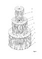
- the essentially circular basic modules 5 ', 5 “, 5'” are stacked in tiers, wherein the base areas of each stacked basic modules 5 ', 5 ", 5"' are smaller, so that there is a pyramidal shape, as shown in the 3-D View in FIG. 4 can be seen.
- the lowermost base module 5 'at the top and bottom each have the same size support plates 4, 4', wherein the upper support plates 4 of the base module 5 'as the lower support plates
- the support struts 2 are then arranged in a circle in such a way that a smaller base area of the basic module 5" placed on the basic module 5 'results on the tra plates 4 of the basic module 5'.
- the support plates 4 "arranged on the support struts 2 of the basic module 5" then again form the lower support plates of the basic module 5 "'provided with an even smaller base area.
- the support struts 2 of the sub-modules 1 are not arranged one above the other, but are offset angularly in the plane, which advantageously contributes to increasing the rigidity of the overall construction.
- the FIG. 4 can be seen that the support struts 2 in sleeve-like receptacles 6, which are arranged on or below the support plates, positioned and thus firmly connected.
Landscapes
- Engineering & Computer Science (AREA)
- General Engineering & Computer Science (AREA)
- Mechanical Engineering (AREA)
- Civil Engineering (AREA)
- Structural Engineering (AREA)
- Wind Motors (AREA)
- Foundations (AREA)
Abstract
Description
- Die vorliegende Erfindung betrifft die Tragstruktur eines Offshore-Bauwerks, insbesondere einer Windenergieanlage gemäß dem Oberbegriff des Patentanspruchs 1.
- Bisherige Offshore Windenergieanlagen können in zwei Konstruktionsbereiche unterteilt werden. Der erste Teil ist die hochgradig ermüdungsbeanspruchte Tragstruktur. Diese beginnt am Meeresboden und erreicht ihr Ende an der Flanschverbindung zum Turm der Windenergieanlage. Die Flanschverbindung trägt den Turm und die Turbine und leitet die dadurch hervorgerufenen Lasten und Einwirkungen ab.
- Der zweite Teil ist das eigentliche Fundament, welches z.B. als ein mit dem Meeresboden verankerbares Gründungselement oder als Schwerkraftfundament ausgebildet ist. Das Fundament nimmt die durch die Tragstruktur, den Turm und die Windturbine hervorgerufenen Lasten auf, trägt diese in den Meeresboden ab. Die gesamte Konstruktion, bestehend aus Gründung mit Fundament und Tragstruktur sowie Turm und Turbine, wird als Offshore-Windenergieanlage (OWEA) bezeichnet.
- Aus dem Stand der Technik sind als Tragstrukturen z.B. Gittermastkonstruktionen bekannt (
EP 2 067 913 A2 oderDE 20 2011 101 599 U 1 ), die als dreidimensionale Rahmentragwerke ausgebildet sind. - Bei der in der
EP 2 067 913 A2 beschriebenen Gittermastkonstruktion besteht die Gitterstruktur aus mehreren Fachwerkrahmen, die ihrerseits aus senkrechten oder leicht geneigten Tragstreben in den Kanten- bzw. Eckbereichen und vorzugsweise diagonal gerichteten Streben zur Versteifung bestehen. Da die einzelnen Trag-Versteifungsstreben des Fachwerkrahmens an einem Punkt zusammenstoßen, sind separat gefertigte Knotenteile vorgesehen, mit denen die sich in unterschiedliche Richtungen des Fachwerks verzweigenden Streben miteinander verbunden werden können. Dabei ist die gesamte aus Einzelteilen zusammengesetzte Konstruktion für den jeweiligen spezifischen Einzelfall ausgelegt. - Auch bei der aus der
DE 20 2011 101 599 U1 bekannten Gitterkonstruktion sind die Streben der einzelnen Fachwerkrahmen ebenfalls mittels separater Knotenteile miteinander verbunden. - Nachteilig bei diesen bekannten Gittermastkonstruktionen ist zum Einen die aufwändige Bauweise, bei der mittels separat herzustellenden Knotenteilen die Streben der einzelnen Fachwerkrahmen miteinander verbunden werden müssen. Nachteilig ist weiterhin die aufwändige Anpassung der Konstruktion an unterschiedliche statische Erfordernisse, d.h. es sind jeweils Einzelanfertigungen notwendig, die hohen Planungs-, Fertigungs- und Montageaufwand erfordern und damit unter wirtschaftlichen Gesichtspunkten noch nicht optimal ausgelegt sind.
- Aufgabe der Erfindung ist es, eine Tragstruktur eines Offshore-Bauwerks insbesondere einer Windenergieanlage anzugeben, die einfach und kostengünstig an unterschiedliche statische Erfordernisse anpassbar ist und den Planungs-, Fertigungs- und Montageaufwand deutlich reduziert.
- Die Lehre der Erfindung umfasst eine Tragstruktur eines Offshore-Bauwerks, insbesondere einer Windenergieanlage, bestehend aus mindestens einem Grundmodul mit vorbestimmter statischer Tragfähigkeit, wobei das Grundmodul aus mindestens zwei baukastenartig zusammengesetzten Teilmodulen mit vorbestimmter statischer Tragfähigkeit besteht und die Teilmodule aus Tragplatten mit dazwischen angeordneten Tragstreben und zwischen den Tragstreben angeordneten Versteifungsstreben zusammengesetzt sind und wobei die Versteifungsstreben mit den Tragstreben außerhalb der Verbindungsstellen der Tragstreben mit den Tragplatten und damit knotenfrei angeordnet sind.
- Eine Ausgestaltung der Erfindung sieht vor, dass die Tragstruktur aus mindestens zwei baukastenartig aufeinandergesetzten und/oder nebeneinander angeordneten und miteinander verbundenen Grundmodulen mit vorbestimmter statischer Tragfähigkeit besteht, um so verschiedenste Formen von Gründungskonstruktionen realisieren zu können.
- Wenngleich die Erfindung vorteilhaft für Offshore Windenergieanlagen geeignet ist, ist sie jedoch nicht hierauf beschränkt. Vorstellbar ist auch eine vorteilhafte Verwendung z.B. als Tragstruktur für Bohrplattformen.
- Mit der vorgeschlagenen Tragstruktur beinhaltet die Erfindung eine kostengünstige und zeitsparende Konstruktion, mit der flexibel auf unterschiedliche statische Erfordernisse reagiert und auf separat hergestellte Knotenteile verzichtet werden kann.
- Gemäß der Lehre der Erfindung liegt der Hauptnutzen vor allem darin, dass durch das baukastenartige Zusammensetzen der Tragstruktur aus statisch vorbestimmten Teilmodulen zu einem statisch vorbestimmten Grundmodul und das Aufeinandersetzen der einzelnen Grundmodule letztendlich zu einer Tragstruktur der Planungs- und Fertigungsaufwand deutlich reduziert werden kann. Die einzelnen Grundmodule werden dabei erfindungsgemäß etagenweise bis zur erforderlichen Höhe aufeinandergesetzt oder z.B. für Bohrplattformen nebeneinandergesetzt und mit einander verbunden.
- Da die Teilmodule sehr einfach entsprechend den statischen Erfordernissen als Standardmodul vorgefertigt und bereits werksseitig zu einem Grundmodul zusammengesetzt werden können, ist der Fertigungsaufwand und die Montagedauer auf der Baustelle deutlich verkürzt, was die Gesamtkosten der Herstellung und Montage der Tragkonstruktion deutlich reduziert.
- Da die Versteifungsstreben der einzelnen Teilmodule der Tragstruktur außerhalb der Verbindungsstellen der Tragstreben mit den Tragplatten knotenfrei angeordnet sind, also aus statischen Gründen keine Abzweigungen an den Verbindungsstellen erforderlich sind, kann auf Knotenteile verzichtet werden, was die Fertigungskosten erheblich reduziert.
- Im Vergleich zu bekannten Lösungen ist die erfindungsgemäße Tragkonstruktion daher wesentlich einfacher, schneller und kostengünstiger zu realisieren.
- Der Grundriss der Grundmodule kann den jeweiligen Erfordernissen flexibel angepasst werden. Neben runden, dreieckigen, rechteckigen oder quadratischen Grundflächen können auch sechs-, achteckige oder polygonale Grundflächen realisiert werden. Zur flexiblen Gestaltung unterschiedlicher Grundflächen der Grundmodule sind die Teilmodule im Grundriss ebenfalls beliebig gestaltbar, wobei diese vorteilhaft dreieckförmig, rechteckig oder quadratisch ausgebildet sind, so dass sie je nach Erfordernis zu unterschiedlich ausgebildeten Grundflächen des Grundmoduls zusammengesetzt werden können. So ist es beispielsweise möglich, aus mehreren im Grundriss dreieckförmigen Teilmodulen, ein Sechs-, Acht- oder Vieleck als Grundriss für das Grundmodul der Tragkonstruktion zu erzeugen, so dass eine vielfältige, den Erfordernissen anpassbare geometrische Grundrissgestaltung der Tragkonstruktion ermöglicht wird.
- Während die Tragplatten der Teilmodule z.B. aus Grobblechstahl gefertigt sein können, sind die Trag- und Versteifungsstreben vorzugsweise aus nahtlosen oder geschweißten Stahlrohren hergestellt, deren Geometrie (Durchmesser, Wanddicke) und Werkstoff den unterschiedlichen statischen Erfordernissen angepasst sind.
- In einer vorteilhaften Weiterbildung der Erfindung werden die einzelnen Tragstreben nicht aus einem, den statischen Erfordernissen entsprechend dimensionierten Einzelrohr gebildet, sondern aus einem bambusartig zusammengesetzten Rohrbündel. Die einzelnen Rohre des Rohrbündels sind wie bei einem Bambus angeordnet, z.B. mit einem Zentralrohr mit über den Umfang angeordneten weiteren Rohren. Es sind auch ringförmige Strukturen denkbar, bei denen auf einem Kreisring oder auf mehreren konzentrischen Kreisen Rohre fest angeordnet und miteinander verbunden sind. Hierdurch wird eine extrem hohe statische und dynamische Biegesteifigkeit der Tragkonstruktion bei kleineren Abmessungen und vergleichsweise geringem Eigengewicht erreicht. Dies spart Material- und Herstellkosten. Gerade bei den bei Offshore-Bauwerken auftretenden dynamischen Beanspruchungen durch Windstöße und Wellenschläge haben sich derartige Strukturen als sehr vorteilhaft erwiesen.
- Zum Schutz vor Korrosionseinflüssen können alle Komponenten der Tragkonstruktion vorteilhaft mit einer Beschichtung und/oder mit kathodischem Korrosionsschutz (KKS) versehen sein.
- In einer weiteren vorteilhaften Ausgestaltung der Erfindung werden die Grundmodule aus bereits vorgefertigten Teilmodulen hergestellt, was die Bauzeit und damit die Herstellkosten erheblich reduziert. Dazu werden für die einzelnen Teilmodule zunächst die Tragplatten entsprechend dem herzustellenden Grundriss der Grundmodule bzw. der Tragkonstruktion zugeschnitten und anschließend die Trag- und Versteifungsstreben zwischen den Tragplatten angeordnet und verschweißt.
- Die so vorgefertigten Teilmodule werden dann entsprechend dem geforderten Grundriss des Grundmoduls zusammengefügt. Hierbei kann ein Grundmodul bereits den geforderten Grundriss der gesamten Tragkonstruktion aufweisen oder der Grundriss der Tragkonstruktion wird durch Zusammenfügen mehrerer Grundmodule in einer Ebene erzeugt.
- Zur Vereinfachung der Positionierung und Verbindung der Tragstreben mit den Tragplatten ist es vorteilhaft, die Tragplatten an den entsprechenden Stellen mit hülsenartigen Aufnahmen zu versehen, mittels derer die Tragstreben quasi mit Zwangsführung mit den Tragplatten verbunden werden. Diese hülsenartigen Aufnahmen können z.B. mit den Tragplatten verschweißte Rohrabschnitte sein, die einen geringfügig größeren Durchmesser aufweisen als die darin einzuführenden Tragstreben.An den Tragstreben werden dann die Versteifungsstreben in der Weise angeordnet, dass sich diese außerhalb der Verbindungsstellen von Tragstreben und Tragplatten der aufeinandergesetzten Grundmodule befinden, so dass auf Knotenteile verzichtet werden kann. Die Versteifungsstreben sind in vertikaler Richtung gesehen vorteilhaft diagonal ausgerichtet und verbinden jeweils zwei Tragstreben eines Teilmoduls.
- Die erforderliche Gesamthöhe der Tragkonstruktion wird durch ein etagenweises Aufeinandersetzen der einzelnen Grundmodule erreicht, wobei die Tragplatten des aus den Teilmodulen zusammengesetzten Grundmoduls, welches auf das jeweils untere aufgesetzt wird, als Zwischenplatten fungieren.
- Zur Vereinfachung der Montage weisen diese Zwischenplatten vorteilhaft sowohl auf der Ober- wie auf der Unterseite hülsenartige Aufnahmen für die jeweils oberhalb und unterhalb der Tragplatten anzuschließenden Tragstreben auf.
- Zur Realisierung einer pyramidalen also einer vom Meeresboden bis zum Turm sich verjüngenden Struktur der Gesamtkonstruktion weisen die aufeinanderzusetzenden Grundmodule jeweils eine sich verringernde Grundfläche auf.
- Beim Aufeinandersetzen der Grundmodule ist es vorteilhaft, wenn in vertikaler Richtung gesehen die Tragstreben der Teilmodule nicht fluchtend übereinander angeordnet sind, sondern in der Ebene versetzt sind, da dies vorteilhaft zur Erhöhung der Steifigkeit der Gesamtkonstruktion beiträgt.
- Neben einem aktiven oder passiven Korrosionsschutz der Tragkonstruktion können die Verbindungsstellen der Tragstreben mit der Tragplatte mit den hülsenartigen Aufnahmen zusätzlich separat geschützt werden. Dazu weisen die Tragplatten derTeilmodule bzw. des Grundmoduls nach einer vorteilhaften Ausgestaltung der Erfindung in den Randbereichen einen Kragen auf, wodurch eine Wanne entsteht, die z.B. mit Zementmörtel gefüllt werden kann, der die Verbindungsstellen umschließt und so vor Korrosion schützt.
- Es ist aber auch möglich, nur einen begrenzten Bereich um die jeweiligen Verbindungsstellen der Tragstreben mit der Tragplatte mit einem zusätzlichen Korrosionsschutz zu versehen.
- Die vorliegende Erfindung wird anhand von Ausführungsformen und weiteren Aspekten und in Verbindung mit den nachfolgenden Figuren weiter erläutert, ohne jedoch darauf beschränkt zu sein. Die Ausführungsformen samt ihrer Varianten sowie die weiteren Aspekte der Erfindung können beliebig miteinander kombiniert werden, sofern sich aus dem Zusammenhang nicht eindeutig das Gegenteil ergibt.
- Es zeigen:
- Figur 1:
- eine schematische Darstellung eines erfindungsgemäßen Teilmoduls einer Tragstruktur in dreieckiger Form,
- Figur 2:
- eine schematische Darstellung rechteckförmiger, aus dreieckförmigen Teilmodulen baukastenartig zusammengesetzter Grundmodule einer Tragstruktur,
- Figur 3:
- eine schematische Darstellung der Draufsicht einer 3-etagigen Tragstruktur aus aufeinandergesetzten Grundmodulen für eine Windenergieanlage, bestehend aus kreisförmig angeordneten und zu Grundmodulen zusammengesetzten dreieckförmigen Teilmodulen,
- Figur 4:
- wie
Figur 3 jedoch in einer 3-D-Ansicht. -
Figur 1 zeigt eine schematische Darstellung eines erfindungsgemäßen Teilmoduls einer Tragstruktur in dreieckiger Form. Das Teilmodul 1 besteht erfindungsgemäß aus Tragplatten 4, 4', zwischen denen Tragstreben 2 und Versteifungsstreben 3 angeordnet sind. Erfindungsgemäß sind die Versteifungsstreben 3 mit den Tragstreben 2 knotenfrei außerhalb der Verbindungsstellen der Tragstreben 2 mit den Tragplatten 4, 4'angeordnet. -
Figur 2 zeigt als Beispiel eine schematische Darstellung eines aus dreieckförmigen Teilmodulen 1 zusammengesetzten rechteckförmigen Grundmoduls 5, welches mit einem weiteren Grundmodul 5 zu einer Tragstruktur zusammengefügt ist, welche z.B. für eine Bohrplattform einsetzbar ist. -
Figur 3 zeigt als weiteres Anwendungsbeispiel die Draufsicht einer 3-etagigen Tragstruktur aus aufeinandergesetzten Grundmodulen 5', 5", 5'" einer Windenergieanlage, bestehend aus kreisförmig angeordneten und zu Grundmodulen 5', 5", 5"' zusammengesetzten dreieckförmigen Teilmodulen 1. Die im Wesentlichen kreisförmigen Grundmodule 5', 5", 5'" sind dabei etagenweise aufeinandergesetzt, wobei die Grundflächen der jeweils aufeinandergesetzten Grundmodule 5', 5", 5"'kleiner werden, so dass sich eine pyramidale Form ergibt, wie sie in der 3-D-Ansicht inFigur 4 zu erkennen ist. Bei den aufeinandergesetzten Grundmodulen 5', 5", 5'" ist zu erkennen, dass das unterste Grundmodul 5' an der Ober- und Unterseite jeweils gleichgroße Tragplatten 4, 4' aufweist, wobei die oberen Tragplatten 4 des Grundmoduls 5' als untere Tragplatten für das Grundmodul 5" dienen. Auf die Traplatten 4 des Grundmoduls 5' sind dann die Tragstreben 2 kreisförmig so angeordnet, dass sich eine kleinere Grundfläche des auf das Grundmodul 5' aufgesetzten Grundmoduls 5" ergibt. Die auf den Tragstreben 2 des Grundmoduls 5" angeordneten Tragplatten 4" bilden dann wieder die unteren Tragplatten des mit einer nochmals kleineren Grundfläche versehenen Grundmoduls 5"'. - Zu erkennen ist in
Figur 4 außerdem, dass in vertikaler Richtung gesehen, die Tragstreben 2 der Teilmodule 1 nicht fluchtend übereinander angeordnet sind, sondern in der Ebene winklig versetzt sind, was vorteilhaft zur Erhöhung der Steifigkeit der Gesamtkonstruktion beiträgt. Weiterhin ist derFigur 4 zu entnehmen, dass die Tragstreben 2 in hülsenartigen Aufnahmen 6, die auf bzw. unter den Tragplatten angeordnet sind, positioniert und damit fest verbunden sind. - Zusammenfassend sind folgende Vorteile der erfindungsgemäßen Gründungskonstruktion zu nennen:
- a) gegenüber dem heutigen Stand der Technik deutlich geringere Planungs- und Montagezeiten,
- b) kostengünstige werkseitige Vorfertigung von statisch vorbestimmten Teil- und Grundmodulen, was die Gesamtkosten der Herstellung und Montage der Tragkonstruktion deutlich reduziert,
- c) Materialersparnis durch einwirkungsoptimierte Struktur der Tragkonstruktion.
-
- 1
- Teilmodul
- 2
- Tragstrebe
- 3
- Versteifungsstrebe
- 4, 4', 4", 4'"
- Tragplatte
- 5, 5', 5", 5'"
- Grundmodul
- 6
- hülsenartige Aufnahme
Claims (13)
- Tragstruktur eines Offshore-Bauwerks, insbesondere einer Windenergieanlage
dadurch gekennzeichnet,
dass die Tragstruktur aus mindestens einem Grundmodul (5, 5', 5", 5"') mit vorbestimmter statischer Tragfähigkeit und das Grundmodul (5, 5', 5", 5"') aus mindestens zwei baukastenartig zusammengesetzten Teilmodulen (1) mit vorbestimmter statischer Tragfähigkeit besteht, wobei die Teilmodule (1) aus Tragplatten (4, 4', 4", 4'") mit dazwischen angeordneten Tragstreben (2) und zwischen den Tragstreben (2) angeordneten Versteifungsstreben (3) zusammengesetzt sind und wobei die Versteifungsstreben (3) außerhalb der Verbindungsstelle der Tragstreben (2) mit der Tragplatte (4, 4', 4", 4"') und damit knotenfrei angeordnet sind. - Tragstruktur nach Anspruch 1
dadurch gekennzeichnet,
dass die Tragstruktur aus mindestens zwei baukastenartig aufeinandergesetzten und/oder nebeneinander angeordneten und miteinander verbundenen Grundmodulen (5, 5', 5", 5"') mit vorbestimmter statischer Tragfähigkeit besteht. - Tragstruktur nach Anspruch 1
dadurch gekennzeichnet,
dass die Grundmodule (5, 5', 5", 5'") aus bereits vorgefertigten Teilmodulen (1) zusammengesetzt sind. - Tragstruktur nach Anspruch 1 und 2
dadurch gekennzeichnet,
dass die Tragplatten (4, 4', 4", 4"') hülsenartige Aufnahmen zur Befestigung der Tragstreben (2) der Teilmodule (1) aufweisen. - Tragstruktur nach einem der Ansprüche 1 bis 3
dadurch gekennzeichnet,
dass das Teilmodul (1) eine dreieck- oder rechteckförmige oder quadratische Grundfläche aufweist. - Tragstruktur nach einem der Ansprüche 1 bis 4
dadurch gekennzeichnet,
dass das Grundmodul (5, 5', 5", 5"') eine dreieck- oder rechteckförmige, quadratische oder polygonale Grundfläche aufweist. - Tragstruktur nach einem der Ansprüche 1 bis 5
dadurch gekennzeichnet,
dass die Tragplatte (4, 4', 4", 4"') aus Grobblechstahl und die Tragstreben (2) und die Versteifungsstreben (3) aus nahtlosen oder geschweißten Stahlrohren hergestellt sind. - Tragstruktur nach Anspruch 6
dadurch gekennzeichnet,
dass die einzelnen Tragstreben (2) aus Bündeln mehrerer Rohre bestehen. - Tragstruktur nach einem der Ansprüche 1 bis 7
dadurch gekennzeichnet,
dass die Tragplatte (4, 4', 4", 4"') wannenartig ausgebildet ist und mit einem die Verbindungsstellen mit den Tragstreben (2) vor Korrosion schützenden Verguss gefüllt ist. - Tragstruktur nach einem der Ansprüche 1 bis 8
dadurch gekennzeichnet,
dass zur Realisierung einer pyramidalen Anordnung der aufeinandergesetzten einzelnen Grundmodule (5, 5', 5", 5"') diese eine jeweils sich verringernde Grundfläche aufweisen. - Tragstruktur nach einem der Ansprüche 1 bis 9
dadurch gekennzeichnet,
dass diese mit einem passiven und/oder aktiven Korrosionsschutz versehen ist. - Verwendung einer Tragstruktur gemäß einem oder mehrerer der Ansprüche 1 bis 10 für Windenergieanlagen oder Bohrplattformen.
- Verfahren zur Herstellung einer Tragstruktur für ein Offshore-Bauwerk gemäß einem oder mehrerer der Ansprüche 1 bis 11,
umfassend den Schritt der Produktion von vorgefertigten statisch bestimmten Teilmodulen, Zusammensetzen der Teilmodule zu einem oder mehreren statisch bestimmten Grundmodulen, Aufeinander- oder Aneinandersetzen und knotenfreies Verbinden der Grundmodule untereinander bis zur vorgesehenen Höhe der Tragstruktur.
Priority Applications (1)
| Application Number | Priority Date | Filing Date | Title |
|---|---|---|---|
| PL13075051T PL2700749T3 (pl) | 2012-08-22 | 2013-08-01 | Struktura nośna budowli przybrzeżnej, zwłaszcza turbiny wiatrowej |
Applications Claiming Priority (1)
| Application Number | Priority Date | Filing Date | Title |
|---|---|---|---|
| DE102012016915.9A DE102012016915B4 (de) | 2012-08-22 | 2012-08-22 | Tragstruktur eines Offshore-Bauwerks, insbesondere einer Windenergieanlage, Verwendung einer derartigen Tragstruktur, sowie Verfahren zu deren Herstellung |
Publications (3)
| Publication Number | Publication Date |
|---|---|
| EP2700749A2 true EP2700749A2 (de) | 2014-02-26 |
| EP2700749A3 EP2700749A3 (de) | 2016-08-24 |
| EP2700749B1 EP2700749B1 (de) | 2017-10-04 |
Family
ID=49035261
Family Applications (1)
| Application Number | Title | Priority Date | Filing Date |
|---|---|---|---|
| EP13075051.6A Active EP2700749B1 (de) | 2012-08-22 | 2013-08-01 | Tragstruktur eines Offshore-Bauwerks, insbesondere einer Windenergieanlage |
Country Status (6)
| Country | Link |
|---|---|
| EP (1) | EP2700749B1 (de) |
| DE (1) | DE102012016915B4 (de) |
| DK (1) | DK2700749T3 (de) |
| LT (1) | LT2700749T (de) |
| NO (1) | NO2841675T3 (de) |
| PL (1) | PL2700749T3 (de) |
Citations (2)
| Publication number | Priority date | Publication date | Assignee | Title |
|---|---|---|---|---|
| EP2067913A2 (de) | 2007-12-04 | 2009-06-10 | WeserWind GmbH | Gitterstruktur eines Offshore-Bauwerks, insbesondere einer Offshore-Windenergieanlage |
| DE202011101599U1 (de) | 2011-05-12 | 2011-09-23 | Emilio Reales Bertomeo | Offshore-Fundament für Windenergieanlagen |
Family Cites Families (3)
| Publication number | Priority date | Publication date | Assignee | Title |
|---|---|---|---|---|
| US3906734A (en) * | 1973-08-23 | 1975-09-23 | Texaco Inc | Fixed marine platform with dispersed base |
| JPS61501860A (ja) * | 1984-04-12 | 1986-08-28 | プロエクトヌイ イ ナウクノ−イススレドワテルスキイ インスチトウト“ロストフスキイ プロムストロイニイプロエクト” | 強化コンクリ−ト製海上プラットホ−ム |
| FR2760474B1 (fr) * | 1997-03-07 | 1999-05-28 | Technip Geoproduction | Procede d'assemblage de troncons de jambes de support d'une plate-forme petroliere |
-
2012
- 2012-08-22 DE DE102012016915.9A patent/DE102012016915B4/de not_active Expired - Fee Related
-
2013
- 2013-04-26 NO NO13780628A patent/NO2841675T3/no unknown
- 2013-08-01 LT LTEP13075051.6T patent/LT2700749T/lt unknown
- 2013-08-01 EP EP13075051.6A patent/EP2700749B1/de active Active
- 2013-08-01 DK DK13075051.6T patent/DK2700749T3/en active
- 2013-08-01 PL PL13075051T patent/PL2700749T3/pl unknown
Patent Citations (2)
| Publication number | Priority date | Publication date | Assignee | Title |
|---|---|---|---|---|
| EP2067913A2 (de) | 2007-12-04 | 2009-06-10 | WeserWind GmbH | Gitterstruktur eines Offshore-Bauwerks, insbesondere einer Offshore-Windenergieanlage |
| DE202011101599U1 (de) | 2011-05-12 | 2011-09-23 | Emilio Reales Bertomeo | Offshore-Fundament für Windenergieanlagen |
Also Published As
| Publication number | Publication date |
|---|---|
| PL2700749T3 (pl) | 2018-03-30 |
| DE102012016915B4 (de) | 2017-10-19 |
| DE102012016915A1 (de) | 2014-02-27 |
| EP2700749A3 (de) | 2016-08-24 |
| EP2700749B1 (de) | 2017-10-04 |
| NO2841675T3 (de) | 2018-05-05 |
| LT2700749T (lt) | 2017-11-27 |
| DK2700749T3 (en) | 2018-01-02 |
Similar Documents
| Publication | Publication Date | Title |
|---|---|---|
| EP2932095B1 (de) | Übergangskörper zur anordnung zwischen unterschiedlich ausgeführten abschnitten eines windkraftanlagenturms und windkraftanlagenturm mit einem solchen übergangskörper | |
| EP2109704B1 (de) | Windkraftanlage | |
| EP2522780B1 (de) | Offshore-Fundament für Windenergieanlagen | |
| DE602005002760T2 (de) | Windkraftanlageturm, vorgefertigtes metallisches Wandteil zum Gebrauch in diesem Turm, und Verfahren zur Herstellung dieses Turms | |
| DE102012106772A1 (de) | Modularer Turm einer Windkraftanlage | |
| EP0960986A2 (de) | Verfahren und Vorrichtung zum Herstellen von hohen, hohlen, turmartigen Bauwerken von zweihundert Metern Höhe und mehr, insbesondere von Türmen für Windkraftanlagen | |
| EP1631722A2 (de) | Fundament für eine windenergieanlage | |
| EP2839098B1 (de) | Gitterturm für windenergieanlagen und verfahren zur errichtung eines solchen gitterturmes | |
| EP3208405B1 (de) | Vorrichtung und verfahren zur errichtung von turmartigen bauwerken aus fertigteilelementen | |
| EP3491239B1 (de) | Verbindungselement zum verbinden von turmabschnitten, turmabschnitt, turm, windenergieanlage sowie verfahren zum herstellen eines turmabschnitts und zum verbinden von turmabschnitten | |
| EP3230539B1 (de) | Verfahren zum errichten eines rohrturmbauwerks und rohrturmbauwerk | |
| DE102010012094B3 (de) | Gitterstruktur einer turmförmigen Gründung einer Offshore-Windenergieanlage sowie modulare Offshore-WEA-Gründung mit derselben | |
| DE102015115645A1 (de) | Verfahren zur Herstellung und zum Errichten eines Rohrturmbauwerks | |
| EP3320161B1 (de) | Turm einer windkraftanlage | |
| EP2692967A2 (de) | Verfahren zum Errichten eines Turmes aus Stahl einer Windenergieanlage und Turm aus Stahl für eine Windenergieanlage | |
| WO2016026603A1 (de) | Betonkonstruktion in modulbauweise | |
| EP3467236B1 (de) | Turm, insbesondere für eine windenergieanlage | |
| EP2828523B1 (de) | Offshore-tragstruktur für windenergieanlagen, sowie stabwerkelement für selbige | |
| DE102014118251B4 (de) | Verfahren zur Herstellung und zum Errichten eines Rohrturmbauwerks | |
| EP2700749B1 (de) | Tragstruktur eines Offshore-Bauwerks, insbesondere einer Windenergieanlage | |
| EP4051854A1 (de) | Holzfachwerkturm für windkraftanlagen | |
| DE102005014025A1 (de) | Als Stahlfachwerkkonstruktion ausgebildeter Turm, vorzugsweise für Windkraftanlagen | |
| EP0659952B1 (de) | Rohrspindeltreppe sowie Anordnung aus mehreren Rohrspindeltreppen | |
| DE102019218687A1 (de) | Übergangsstück für einen Turm einer Windenergieanlage und Turm einer Windenergieanlage | |
| EP3208385A1 (de) | Tragwerk |
Legal Events
| Date | Code | Title | Description |
|---|---|---|---|
| PUAI | Public reference made under article 153(3) epc to a published international application that has entered the european phase |
Free format text: ORIGINAL CODE: 0009012 |
|
| AK | Designated contracting states |
Kind code of ref document: A2 Designated state(s): AL AT BE BG CH CY CZ DE DK EE ES FI FR GB GR HR HU IE IS IT LI LT LU LV MC MK MT NL NO PL PT RO RS SE SI SK SM TR |
|
| AX | Request for extension of the european patent |
Extension state: BA ME |
|
| PUAL | Search report despatched |
Free format text: ORIGINAL CODE: 0009013 |
|
| AK | Designated contracting states |
Kind code of ref document: A3 Designated state(s): AL AT BE BG CH CY CZ DE DK EE ES FI FR GB GR HR HU IE IS IT LI LT LU LV MC MK MT NL NO PL PT RO RS SE SI SK SM TR |
|
| AX | Request for extension of the european patent |
Extension state: BA ME |
|
| RIC1 | Information provided on ipc code assigned before grant |
Ipc: E02B 17/00 20060101ALI20160718BHEP Ipc: E02B 17/02 20060101AFI20160718BHEP |
|
| 17P | Request for examination filed |
Effective date: 20170223 |
|
| RBV | Designated contracting states (corrected) |
Designated state(s): AL AT BE BG CH CY CZ DE DK EE ES FI FR GB GR HR HU IE IS IT LI LT LU LV MC MK MT NL NO PL PT RO RS SE SI SK SM TR |
|
| GRAP | Despatch of communication of intention to grant a patent |
Free format text: ORIGINAL CODE: EPIDOSNIGR1 |
|
| INTG | Intention to grant announced |
Effective date: 20170410 |
|
| GRAS | Grant fee paid |
Free format text: ORIGINAL CODE: EPIDOSNIGR3 |
|
| GRAA | (expected) grant |
Free format text: ORIGINAL CODE: 0009210 |
|
| AK | Designated contracting states |
Kind code of ref document: B1 Designated state(s): AL AT BE BG CH CY CZ DE DK EE ES FI FR GB GR HR HU IE IS IT LI LT LU LV MC MK MT NL NO PL PT RO RS SE SI SK SM TR |
|
| REG | Reference to a national code |
Ref country code: GB Ref legal event code: FG4D Free format text: NOT ENGLISH |
|
| REG | Reference to a national code |
Ref country code: CH Ref legal event code: EP |
|
| REG | Reference to a national code |
Ref country code: AT Ref legal event code: REF Ref document number: 934171 Country of ref document: AT Kind code of ref document: T Effective date: 20171015 |
|
| REG | Reference to a national code |
Ref country code: IE Ref legal event code: FG4D Free format text: LANGUAGE OF EP DOCUMENT: GERMAN |
|
| REG | Reference to a national code |
Ref country code: DE Ref legal event code: R096 Ref document number: 502013008466 Country of ref document: DE |
|
| REG | Reference to a national code |
Ref country code: SE Ref legal event code: TRGR |
|
| REG | Reference to a national code |
Ref country code: DK Ref legal event code: T3 Effective date: 20171221 |
|
| REG | Reference to a national code |
Ref country code: NL Ref legal event code: FP |
|
| REG | Reference to a national code |
Ref country code: EE Ref legal event code: FG4A Ref document number: E014788 Country of ref document: EE Effective date: 20171102 |
|
| REG | Reference to a national code |
Ref country code: NO Ref legal event code: T2 Effective date: 20171004 |
|
| PG25 | Lapsed in a contracting state [announced via postgrant information from national office to epo] |
Ref country code: ES Free format text: LAPSE BECAUSE OF FAILURE TO SUBMIT A TRANSLATION OF THE DESCRIPTION OR TO PAY THE FEE WITHIN THE PRESCRIBED TIME-LIMIT Effective date: 20171004 |
|
| PG25 | Lapsed in a contracting state [announced via postgrant information from national office to epo] |
Ref country code: BG Free format text: LAPSE BECAUSE OF FAILURE TO SUBMIT A TRANSLATION OF THE DESCRIPTION OR TO PAY THE FEE WITHIN THE PRESCRIBED TIME-LIMIT Effective date: 20180104 Ref country code: RS Free format text: LAPSE BECAUSE OF FAILURE TO SUBMIT A TRANSLATION OF THE DESCRIPTION OR TO PAY THE FEE WITHIN THE PRESCRIBED TIME-LIMIT Effective date: 20171004 Ref country code: GR Free format text: LAPSE BECAUSE OF FAILURE TO SUBMIT A TRANSLATION OF THE DESCRIPTION OR TO PAY THE FEE WITHIN THE PRESCRIBED TIME-LIMIT Effective date: 20180105 Ref country code: HR Free format text: LAPSE BECAUSE OF FAILURE TO SUBMIT A TRANSLATION OF THE DESCRIPTION OR TO PAY THE FEE WITHIN THE PRESCRIBED TIME-LIMIT Effective date: 20171004 |
|
| REG | Reference to a national code |
Ref country code: DE Ref legal event code: R097 Ref document number: 502013008466 Country of ref document: DE |
|
| PG25 | Lapsed in a contracting state [announced via postgrant information from national office to epo] |
Ref country code: CZ Free format text: LAPSE BECAUSE OF FAILURE TO SUBMIT A TRANSLATION OF THE DESCRIPTION OR TO PAY THE FEE WITHIN THE PRESCRIBED TIME-LIMIT Effective date: 20171004 Ref country code: SK Free format text: LAPSE BECAUSE OF FAILURE TO SUBMIT A TRANSLATION OF THE DESCRIPTION OR TO PAY THE FEE WITHIN THE PRESCRIBED TIME-LIMIT Effective date: 20171004 |
|
| PLBE | No opposition filed within time limit |
Free format text: ORIGINAL CODE: 0009261 |
|
| STAA | Information on the status of an ep patent application or granted ep patent |
Free format text: STATUS: NO OPPOSITION FILED WITHIN TIME LIMIT |
|
| REG | Reference to a national code |
Ref country code: FR Ref legal event code: PLFP Year of fee payment: 6 |
|
| PG25 | Lapsed in a contracting state [announced via postgrant information from national office to epo] |
Ref country code: IT Free format text: LAPSE BECAUSE OF FAILURE TO SUBMIT A TRANSLATION OF THE DESCRIPTION OR TO PAY THE FEE WITHIN THE PRESCRIBED TIME-LIMIT Effective date: 20171004 Ref country code: RO Free format text: LAPSE BECAUSE OF FAILURE TO SUBMIT A TRANSLATION OF THE DESCRIPTION OR TO PAY THE FEE WITHIN THE PRESCRIBED TIME-LIMIT Effective date: 20171004 Ref country code: SM Free format text: LAPSE BECAUSE OF FAILURE TO SUBMIT A TRANSLATION OF THE DESCRIPTION OR TO PAY THE FEE WITHIN THE PRESCRIBED TIME-LIMIT Effective date: 20171004 |
|
| 26N | No opposition filed |
Effective date: 20180705 |
|
| PG25 | Lapsed in a contracting state [announced via postgrant information from national office to epo] |
Ref country code: MT Free format text: LAPSE BECAUSE OF FAILURE TO SUBMIT A TRANSLATION OF THE DESCRIPTION OR TO PAY THE FEE WITHIN THE PRESCRIBED TIME-LIMIT Effective date: 20171004 |
|
| PG25 | Lapsed in a contracting state [announced via postgrant information from national office to epo] |
Ref country code: SI Free format text: LAPSE BECAUSE OF FAILURE TO SUBMIT A TRANSLATION OF THE DESCRIPTION OR TO PAY THE FEE WITHIN THE PRESCRIBED TIME-LIMIT Effective date: 20171004 |
|
| PG25 | Lapsed in a contracting state [announced via postgrant information from national office to epo] |
Ref country code: MC Free format text: LAPSE BECAUSE OF FAILURE TO SUBMIT A TRANSLATION OF THE DESCRIPTION OR TO PAY THE FEE WITHIN THE PRESCRIBED TIME-LIMIT Effective date: 20171004 |
|
| REG | Reference to a national code |
Ref country code: CH Ref legal event code: PL |
|
| PG25 | Lapsed in a contracting state [announced via postgrant information from national office to epo] |
Ref country code: LI Free format text: LAPSE BECAUSE OF NON-PAYMENT OF DUE FEES Effective date: 20180831 Ref country code: LU Free format text: LAPSE BECAUSE OF NON-PAYMENT OF DUE FEES Effective date: 20180801 Ref country code: CH Free format text: LAPSE BECAUSE OF NON-PAYMENT OF DUE FEES Effective date: 20180831 |
|
| REG | Reference to a national code |
Ref country code: BE Ref legal event code: MM Effective date: 20180831 |
|
| PG25 | Lapsed in a contracting state [announced via postgrant information from national office to epo] |
Ref country code: BE Free format text: LAPSE BECAUSE OF NON-PAYMENT OF DUE FEES Effective date: 20180831 |
|
| REG | Reference to a national code |
Ref country code: AT Ref legal event code: MM01 Ref document number: 934171 Country of ref document: AT Kind code of ref document: T Effective date: 20180801 |
|
| PG25 | Lapsed in a contracting state [announced via postgrant information from national office to epo] |
Ref country code: AT Free format text: LAPSE BECAUSE OF NON-PAYMENT OF DUE FEES Effective date: 20180801 |
|
| PG25 | Lapsed in a contracting state [announced via postgrant information from national office to epo] |
Ref country code: TR Free format text: LAPSE BECAUSE OF FAILURE TO SUBMIT A TRANSLATION OF THE DESCRIPTION OR TO PAY THE FEE WITHIN THE PRESCRIBED TIME-LIMIT Effective date: 20171004 |
|
| PG25 | Lapsed in a contracting state [announced via postgrant information from national office to epo] |
Ref country code: PT Free format text: LAPSE BECAUSE OF FAILURE TO SUBMIT A TRANSLATION OF THE DESCRIPTION OR TO PAY THE FEE WITHIN THE PRESCRIBED TIME-LIMIT Effective date: 20171004 Ref country code: HU Free format text: LAPSE BECAUSE OF FAILURE TO SUBMIT A TRANSLATION OF THE DESCRIPTION OR TO PAY THE FEE WITHIN THE PRESCRIBED TIME-LIMIT; INVALID AB INITIO Effective date: 20130801 |
|
| PG25 | Lapsed in a contracting state [announced via postgrant information from national office to epo] |
Ref country code: MK Free format text: LAPSE BECAUSE OF NON-PAYMENT OF DUE FEES Effective date: 20171004 Ref country code: CY Free format text: LAPSE BECAUSE OF FAILURE TO SUBMIT A TRANSLATION OF THE DESCRIPTION OR TO PAY THE FEE WITHIN THE PRESCRIBED TIME-LIMIT Effective date: 20171004 |
|
| PG25 | Lapsed in a contracting state [announced via postgrant information from national office to epo] |
Ref country code: AL Free format text: LAPSE BECAUSE OF FAILURE TO SUBMIT A TRANSLATION OF THE DESCRIPTION OR TO PAY THE FEE WITHIN THE PRESCRIBED TIME-LIMIT Effective date: 20171004 |
|
| REG | Reference to a national code |
Ref country code: EE Ref legal event code: HC1A Ref document number: E014788 Country of ref document: EE |
|
| PGFP | Annual fee paid to national office [announced via postgrant information from national office to epo] |
Ref country code: NL Payment date: 20240821 Year of fee payment: 12 |
|
| PGFP | Annual fee paid to national office [announced via postgrant information from national office to epo] |
Ref country code: IS Payment date: 20240814 Year of fee payment: 12 |
|
| PGFP | Annual fee paid to national office [announced via postgrant information from national office to epo] |
Ref country code: DE Payment date: 20240821 Year of fee payment: 12 Ref country code: FI Payment date: 20240821 Year of fee payment: 12 Ref country code: IE Payment date: 20240827 Year of fee payment: 12 Ref country code: LT Payment date: 20240724 Year of fee payment: 12 |
|
| PGFP | Annual fee paid to national office [announced via postgrant information from national office to epo] |
Ref country code: DK Payment date: 20240829 Year of fee payment: 12 |
|
| PGFP | Annual fee paid to national office [announced via postgrant information from national office to epo] |
Ref country code: GB Payment date: 20240826 Year of fee payment: 12 |
|
| PGFP | Annual fee paid to national office [announced via postgrant information from national office to epo] |
Ref country code: FR Payment date: 20240829 Year of fee payment: 12 |
|
| PGFP | Annual fee paid to national office [announced via postgrant information from national office to epo] |
Ref country code: EE Payment date: 20240821 Year of fee payment: 12 |
|
| PGFP | Annual fee paid to national office [announced via postgrant information from national office to epo] |
Ref country code: PL Payment date: 20240718 Year of fee payment: 12 |
|
| PGFP | Annual fee paid to national office [announced via postgrant information from national office to epo] |
Ref country code: LV Payment date: 20240819 Year of fee payment: 12 |
|
| PGFP | Annual fee paid to national office [announced via postgrant information from national office to epo] |
Ref country code: NO Payment date: 20240829 Year of fee payment: 12 Ref country code: SE Payment date: 20240821 Year of fee payment: 12 |
|
| REG | Reference to a national code |
Ref country code: LT Ref legal event code: MM4D Effective date: 20250801 |
|
| REG | Reference to a national code |
Ref country code: DE Ref legal event code: R119 Ref document number: 502013008466 Country of ref document: DE |
|
| REG | Reference to a national code |
Ref country code: DK Ref legal event code: EBP Effective date: 20250831 |
|
| REG | Reference to a national code |
Ref country code: NL Ref legal event code: MM Effective date: 20250901 |
|
| PG25 | Lapsed in a contracting state [announced via postgrant information from national office to epo] |
Ref country code: LT Free format text: LAPSE BECAUSE OF NON-PAYMENT OF DUE FEES Effective date: 20250801 |
|
| PG25 | Lapsed in a contracting state [announced via postgrant information from national office to epo] |
Ref country code: NO Free format text: LAPSE BECAUSE OF NON-PAYMENT OF DUE FEES Effective date: 20250831 |
|
| PG25 | Lapsed in a contracting state [announced via postgrant information from national office to epo] |
Ref country code: FI Free format text: LAPSE BECAUSE OF NON-PAYMENT OF DUE FEES Effective date: 20250801 |
|
| PG25 | Lapsed in a contracting state [announced via postgrant information from national office to epo] |
Ref country code: LV Free format text: LAPSE BECAUSE OF NON-PAYMENT OF DUE FEES Effective date: 20250801 Ref country code: EE Free format text: LAPSE BECAUSE OF NON-PAYMENT OF DUE FEES Effective date: 20250831 |