EP2700809A1 - Elektrifizierungssteuerungsvorrichtung für eine zündkerze - Google Patents
Elektrifizierungssteuerungsvorrichtung für eine zündkerze Download PDFInfo
- Publication number
- EP2700809A1 EP2700809A1 EP12773846.6A EP12773846A EP2700809A1 EP 2700809 A1 EP2700809 A1 EP 2700809A1 EP 12773846 A EP12773846 A EP 12773846A EP 2700809 A1 EP2700809 A1 EP 2700809A1
- Authority
- EP
- European Patent Office
- Prior art keywords
- energization
- glow
- glow plugs
- wire breakage
- plugs
- Prior art date
- Legal status (The legal status is an assumption and is not a legal conclusion. Google has not performed a legal analysis and makes no representation as to the accuracy of the status listed.)
- Granted
Links
Images


Classifications
-
- F—MECHANICAL ENGINEERING; LIGHTING; HEATING; WEAPONS; BLASTING
- F02—COMBUSTION ENGINES; HOT-GAS OR COMBUSTION-PRODUCT ENGINE PLANTS
- F02P—IGNITION, OTHER THAN COMPRESSION IGNITION, FOR INTERNAL-COMBUSTION ENGINES; TESTING OF IGNITION TIMING IN COMPRESSION-IGNITION ENGINES
- F02P19/00—Incandescent ignition, e.g. during starting of internal combustion engines; Combination of incandescent and spark ignition
- F02P19/02—Incandescent ignition, e.g. during starting of internal combustion engines; Combination of incandescent and spark ignition electric, e.g. layout of circuits of apparatus having glowing plugs
- F02P19/025—Incandescent ignition, e.g. during starting of internal combustion engines; Combination of incandescent and spark ignition electric, e.g. layout of circuits of apparatus having glowing plugs with means for determining glow plug temperature or glow plug resistance
-
- F—MECHANICAL ENGINEERING; LIGHTING; HEATING; WEAPONS; BLASTING
- F02—COMBUSTION ENGINES; HOT-GAS OR COMBUSTION-PRODUCT ENGINE PLANTS
- F02P—IGNITION, OTHER THAN COMPRESSION IGNITION, FOR INTERNAL-COMBUSTION ENGINES; TESTING OF IGNITION TIMING IN COMPRESSION-IGNITION ENGINES
- F02P19/00—Incandescent ignition, e.g. during starting of internal combustion engines; Combination of incandescent and spark ignition
- F02P19/02—Incandescent ignition, e.g. during starting of internal combustion engines; Combination of incandescent and spark ignition electric, e.g. layout of circuits of apparatus having glowing plugs
- F02P19/027—Safety devices, e.g. for diagnosing the glow plugs or the related circuits
-
- F—MECHANICAL ENGINEERING; LIGHTING; HEATING; WEAPONS; BLASTING
- F23—COMBUSTION APPARATUS; COMBUSTION PROCESSES
- F23Q—IGNITION; EXTINGUISHING-DEVICES
- F23Q7/00—Incandescent ignition; Igniters using electrically-produced heat, e.g. lighters for cigarettes; Electrically-heated glowing plugs
-
- F—MECHANICAL ENGINEERING; LIGHTING; HEATING; WEAPONS; BLASTING
- F02—COMBUSTION ENGINES; HOT-GAS OR COMBUSTION-PRODUCT ENGINE PLANTS
- F02P—IGNITION, OTHER THAN COMPRESSION IGNITION, FOR INTERNAL-COMBUSTION ENGINES; TESTING OF IGNITION TIMING IN COMPRESSION-IGNITION ENGINES
- F02P19/00—Incandescent ignition, e.g. during starting of internal combustion engines; Combination of incandescent and spark ignition
- F02P19/02—Incandescent ignition, e.g. during starting of internal combustion engines; Combination of incandescent and spark ignition electric, e.g. layout of circuits of apparatus having glowing plugs
-
- F—MECHANICAL ENGINEERING; LIGHTING; HEATING; WEAPONS; BLASTING
- F02—COMBUSTION ENGINES; HOT-GAS OR COMBUSTION-PRODUCT ENGINE PLANTS
- F02P—IGNITION, OTHER THAN COMPRESSION IGNITION, FOR INTERNAL-COMBUSTION ENGINES; TESTING OF IGNITION TIMING IN COMPRESSION-IGNITION ENGINES
- F02P19/00—Incandescent ignition, e.g. during starting of internal combustion engines; Combination of incandescent and spark ignition
- F02P19/02—Incandescent ignition, e.g. during starting of internal combustion engines; Combination of incandescent and spark ignition electric, e.g. layout of circuits of apparatus having glowing plugs
- F02P19/021—Incandescent ignition, e.g. during starting of internal combustion engines; Combination of incandescent and spark ignition electric, e.g. layout of circuits of apparatus having glowing plugs characterised by power delivery controls
- F02P19/022—Incandescent ignition, e.g. during starting of internal combustion engines; Combination of incandescent and spark ignition electric, e.g. layout of circuits of apparatus having glowing plugs characterised by power delivery controls using intermittent current supply
-
- F—MECHANICAL ENGINEERING; LIGHTING; HEATING; WEAPONS; BLASTING
- F02—COMBUSTION ENGINES; HOT-GAS OR COMBUSTION-PRODUCT ENGINE PLANTS
- F02P—IGNITION, OTHER THAN COMPRESSION IGNITION, FOR INTERNAL-COMBUSTION ENGINES; TESTING OF IGNITION TIMING IN COMPRESSION-IGNITION ENGINES
- F02P19/00—Incandescent ignition, e.g. during starting of internal combustion engines; Combination of incandescent and spark ignition
- F02P19/02—Incandescent ignition, e.g. during starting of internal combustion engines; Combination of incandescent and spark ignition electric, e.g. layout of circuits of apparatus having glowing plugs
- F02P19/026—Glow plug actuation during engine operation
-
- G—PHYSICS
- G01—MEASURING; TESTING
- G01R—MEASURING ELECTRIC VARIABLES; MEASURING MAGNETIC VARIABLES
- G01R31/00—Arrangements for testing electric properties; Arrangements for locating electric faults; Arrangements for electrical testing characterised by what is being tested not provided for elsewhere
- G01R31/005—Testing of electric installations on transport means
- G01R31/006—Testing of electric installations on transport means on road vehicles, e.g. automobiles or trucks
- G01R31/007—Testing of electric installations on transport means on road vehicles, e.g. automobiles or trucks using microprocessors or computers
-
- G—PHYSICS
- G01—MEASURING; TESTING
- G01R—MEASURING ELECTRIC VARIABLES; MEASURING MAGNETIC VARIABLES
- G01R31/00—Arrangements for testing electric properties; Arrangements for locating electric faults; Arrangements for electrical testing characterised by what is being tested not provided for elsewhere
- G01R31/50—Testing of electric apparatus, lines, cables or components for short-circuits, continuity, leakage current or incorrect line connections
- G01R31/54—Testing for continuity
-
- G—PHYSICS
- G01—MEASURING; TESTING
- G01R—MEASURING ELECTRIC VARIABLES; MEASURING MAGNETIC VARIABLES
- G01R31/00—Arrangements for testing electric properties; Arrangements for locating electric faults; Arrangements for electrical testing characterised by what is being tested not provided for elsewhere
- G01R31/50—Testing of electric apparatus, lines, cables or components for short-circuits, continuity, leakage current or incorrect line connections
- G01R31/58—Testing of lines, cables or conductors
Definitions
- the present invention relates to an energization (electrification) control device for a glow plug which is used so as to assist startup or operation of a diesel engine.
- a glow plug including a heat generation resistor which generates heat upon energization has been used so as to assist startup of a diesel engine or to stably operate the diesel engine.
- Examples of conventionally performed energization for such a glow plug are pre-glow energization which is performed for pre-heating of an engine so as to assist startup of the engine, and energization which is performed in a wait state in order to maintain the preheat temperature (hereinafter also referred to as "temperature-maintaining energization").
- temperature-maintaining energization energization
- after-glow energization is performed so as to stabilize combustion during operation of the engine.
- an energization control device which controls electric power supplied from an external power supply such as a battery. Further, in order to perform more accurate energization control, there is also employed a configuration in which electricity supply harness wires from an energization control device are connected individually and directly to a plurality of glow plugs and different control operations are performed for the individual glow plugs (see, for example, Patent Document 1).
- OBD On-Board-Diagnosis
- a wire breakage detection method developed under such circumstances is known.
- a wire breakage detection method is proposed in Patent Document 2.
- a conduction path between a semiconductor switch for switching turn on and off electricity and a glow plug is pulled up to a predetermined voltage (specifically, a voltage supplied from a battery), and wire breakage of the glow plug is detected on the basis of the voltage of the conduction path.
- a predetermined voltage specifically, a voltage supplied from a battery
- the present invention proposes a wire breakage detection method for an energization control device to which a plurality of glow plugs are electrically connected in parallel, the method enabling the energization control device to detect wire breakage of the glow plugs connected thereto.
- the present invention also provides an energization control device for a glow plug which has a wire breakage detection function.
- An energization control device for a glow plug of the present configuration is disposed between a power supply for supplying electric power to a plurality of glow plugs mounted on an engine and the glow plugs, and controls the energization of the glow plugs.
- the energization control device comprises:
- Glow plugs to be mounted on each engine are specified by the specifications and model number of the glow plugs. Accordingly, when the glow plugs to be used are specified, the combined resistance of the glow plugs connected to the glow plug connection portion of the energization control device can be calculated and known in advance. Also, the glow plugs, which are mounted on the engine having a plurality of cylinders, are electrically connected in parallel. Therefore, if wire breakage occurs in the glow plugs, the combined resistance increases. Accordingly, this combined resistance is compared with a predetermined threshold value, and if the combined resistance exceeds the threshold value, it can be determined that wire breakage has occurred in one of the plurality of glow plugs.
- each glow plug has specifications such as resistance, which are specified by its model number.
- glow plugs are industrial products, they have some variation (tolerance). Accordingly, merely setting the threshold on the basis of the resistance (the center value of the resistance) of each glow plug indicated on a specification sheet does not mach necessarily the real situation, and proper performance of wire breakage detection is difficult.
- the combined resistance of the glow plugs used for wire breakage determination is obtained (calculated) from the voltage (value) applied to the glow plugs and the current (value) flowing therethrough, the output of the power supply (e.g., the amount of power generated by a battery or an alternator) changes.
- the resistance of a heat generation resistor which constitutes each glow plug changes, at a rate determined by the temperature coefficient of resistance of a material from which the heat generation resistor is formed, due to heat generation of the heat generation resistor itself and heat transmitted from the engine.
- the positive electrodes of the glow plugs connected to the glow plug connection portion are connected together through an electricity supply harness or an electrode plate, and the negative electrodes of the glow plugs are grounded through a cylinder head to which the glow plugs are fixed, an engine block, or the like. Therefore, the combined resistance of the glow plugs obtained by the energization control device includes these resistances (hereinafter collectively referred to "harness resistance” for convenience), and is not equal to the actual combined resistance of the plurality of glow plugs. In view of this as well, setting of the above-mentioned threshold value is considered to be important.
- the threshold value is set on the basis of the state of energization of the glow plugs, and the comparison between the combined resistance of the glow plugs and the threshold value is performed in the energization state in which the threshold value is set, to thereby determine whether or not wire breakage has occurred in the glow plugs.
- the threshold value is set in accordance with the state of energization of the glow plugs, for example, at the time of completion of pre-glow energization, after elapse of a predetermined period of time after start of temperature-maintaining energization, immediately before cranking at the time of startup of the engine, or during a relatively stable state during after-glow energization.
- the glow plugs are energized in different energization states (for example, a pre-glow energization state, a temperature-maintaining energization state, etc.) in accordance with the values of engine parameters (e.g., the rotational speed of the engine, the temperature of cooling water, the amount of fuel injection, etc.) which affect the temperatures of the glow plugs.
- energization states for example, a pre-glow energization state, a temperature-maintaining energization state, etc.
- the engine is assumed to have four cylinders.
- the combined resistance of the glow plugs becomes 1.3 times.
- the combined resistance of the glow plugs becomes 2 times.
- the resistance of each glow plug which may change among glow plugs of different model numbers, is about 250 m ⁇ when the glow plug is cold, and becomes about 600 m ⁇ when the glow plug reaches the saturated temperature during use in a diesel engine.
- the resistance of the above-mentioned harness which changes in accordance with the type, configuration, etc.
- the threshold value is set under the assumption that wire breakages has occurred in a plurality of glow plugs, whose number is small enough so that wire breakage of the glow plugs does not affect emission or drivability.
- An energization control device for a glow plug of the present configuration is characterized in that the threshold value setting section sets the threshold value when the temperatures of the glow plugs become stable in each energization state; and the resistance obtaining section obtains the combined resistance of the glow plugs when the temperatures of the glow plugs become stable in each energization state.
- the threshold value is set and the combined resistance of the glow plugs is obtained in a state in which the temperatures of the glow plugs are stable. Therefore, the determination as to whether or not wire breakage has occurred in the glow plugs can be made accurately.
- An energization control device for a glow plug of the present configuration is characterized in that in the case where the energization state determination section determines that the energization state is after-glow energization, the threshold value setting section sets the threshold value when the engine is in an idle state, and the resistance obtaining section obtains the combined resistance of the glow plugs when the engine is in the idle state.
- the above-described configuration 3 is employed. Specifically, in the case where the determination as to whether or not wire breakage has occurred in the glow plugs is made during the after-glow energization, the threshold value is set and the combined resistance of the glow plugs is obtained when the engine is in an idle state in which the environment around the glow plugs is relatively stable. Thus, the determination as to whether or not wire breakage has occurred in the glow plugs can be made accurately even during the after-glow energization.
- An energization control device for a glow plug of the present configuration is characterized in that the threshold value setting section sets a plurality of threshold values corresponding to a plurality of different energization states; and the wire breakage detection section determines whether or not wire breakage has occurred in the glow plugs on the basis of the result of comparison between the combined resistance obtained in each energization state and the corresponding threshold value.
- the determination as to whether or not wire breakage has occurred in the glow plugs is performed on the base of the result of comparison between the combined resistance obtained in each of a plurality of different energization states (e.g., at the time of the pre-glow energization and at the time of the after-glow energization) and the corresponding threshold value. Therefore, the determination as to whether or not wire breakage has occurred in the glow plugs can be made more accurately.
- An energization control device for a glow plug of the present configuration is disposed between a power supply for supplying electric power to a plurality of glow plugs mounted on an engine and the glow plugs, and controls the energization of the glow plugs.
- the energization control device comprises:
- the glow plugs mounted on a diesel engine when the glow plugs mounted on a diesel engine is energized first time, the combined resistance of the glow plugs is obtained, and the determination as to whether or not wire breakage has occurred in the glow plugs is made while the obtained combined resistance is used as a reference.
- the term "first time” is used so as to encompass the case where the combined resistance of the glow plugs is obtained when a vehicle completed in a production line is caused to travel by itself for transportation thereof and the case where a manufacturer who produces the vehicle or a dealer who sells the vehicle arbitrary sets the first-time resistance.
- the first-time resistance may be re-obtained by a resetting operation. Accordingly, immediately after replacement of the glow plugs, the first-time resistance can be set again by performing the resetting operation.
- the harness resistance depends on the type, configuration, etc. of the engine, and the harness resistance can be univocally determined for cases where the same engine configuration and the same glow plug attachment configuration are employed. Accordingly, the first-time resistance can be set by performing an experiment, analysis, or calculation in advance for each vehicle model.
- the combined resistance obtained in advance may differ from the combined resistance obtained through actual measurement performed after the glow plugs are attached to the engine. Such difference may be produced due to individual differences produced during manufacture of the engine, the state of connection with the terminal of the electricity supply harness, the contact resistance between the electrode plate or the like and the glow plugs.
- the combined resistance of the glow plugs is obtained and stored before an ordinary engine operation is performed, and wire breakage determination is performed while the stored combined resistance is used as a reference, whereby wire breakage determination for the glow plugs can be performed in a state suitable for each engine.
- the first-time resistance which is actually measured and stored, will be described.
- the glow plugs are energized in different energization states such as pre-glow energization, temperature-maintaining energization, etc.
- the energization state changes, the environment and state of each glow plug, including the temperature thereof, change. Accordingly, when the combined resistance of the glow plugs is compared with the first-time resistance (reference value), obtainment of the combined resistance of the glow plugs must be performed in the same state as the state in which the combined resistance was stored as the first-time resistance.
- the vehicle is manufactured in a production line, and a predetermined number (e.g. 4) of glow plugs are attached to the engine in that process.
- a common electricity supply part such as an electrode plate is connected to the glow plugs, whereby the glow plugs are electrically connected in parallel.
- An energization control device for the glow plugs is mounted in, for example, the engine compartment, and is connected to a battery. Also, a conduction path for supplying electricity to the glow plugs is formed.
- the vehicle manufactured through such a process is caused to travel by itself to a predetermined parking area for shipment.
- pre-heating of the glow plugs (pre-glow energization) is performed so as to start the engine.
- the pre-glow energization is performed over a short period of time (about 2 sec) such that the temperatures of the glow plugs reach 1000°C.
- the key switch is then turned to a start position, the engine starts cranking.
- temperature-maintaining energization is performed for a predetermined period of time so as to enable the glow plugs to maintain the high-temperature state, to thereby enable the engine to start cranking immediately.
- the first-time resistance is obtained in these steps.
- Examples of the preferred timing of obtaining the first-time resistance include a point in time at which the pre-glow energization is completed, a point in time after the temperature-maintaining energization is performed for a predetermined period of time (e.g. 5 sec), a point in time immediately before cranking is started, a point in time during the after-glow energization, and a point in time after the vehicle is stopped.
- timings have a common point that the electric power supplied to the glow plugs under the control corresponding to each state and the temperature of heat generation of the glow plugs as a result of supply of electric power are relatively stable.
- the first-time resistance be a stable value whose fluctuation is minimum.
- the environment within each combustion chamber tends to become instable due to injection of fuel, intake of air and exhaust of gas, explosion of combustion gas, etc. Therefore, it is desirable to monitor these states, select a state suitable for obtaining the first-time resistance, and obtain the first-time resistance in the selected state. Meanwhile, at other points in time, basically, the vehicle and the engine are stopped. Accordingly, the environment surrounding each glow plug is relatively stable, and it can be said that the glow plug is in a state in which disturbances are small; namely, a state in which the same environment can be readily reproduced.
- the first-time resistance may be obtained in any state, when the first-time resistance is obtained, it is stored such that the state in which the first-time resistance was obtained can be identified or distinguished from other states (e.g., RF1, RF2, RF3, etc.).
- the (current) combined resistance of the glow plugs obtained at the time of determination is compared with the above-mentioned first-time resistance.
- This comparison may be performed by simply comparing the magnitudes of the two values, or may be performed by calculating the difference between the two values and using the difference as an index for determination.
- this comparison is performed under the premise that the energization state in which the current combined resistance used for the comparison is obtained is the same energization state in which the first-time resistance, which is the reference for the comparison, was obtained.
- the current combined resistance obtained at the time of completion of the pre-glow energization is used.
- the current combined resistance obtained immediately before the start of cranking is used as the current combined resistance to be compared with the first-time resistance.
- the state (i.e., the energization state) in which the first-time resistance is obtained is the same as the state in which it is compared with the current combined resistance. Therefore, the comparison of the combined resistance of the glow plugs only with the first-time resistance can be readily performed without being affected by the variation of the combined resistance of the glow plugs due to disturbances.
- the combined resistance of the glow plugs which the energization control device obtains from the glow plug connection portion contains various variations and error components.
- the wire breakage determination for the glow plugs can be performed, while at least variations caused by individual differences, harness resistance, etc. are cancelled out.
- the above-described configuration can determine that wire breakage has occurred only when wire breakage has occurred in a large number of glow lugs (three or more glow plugs in the case where the engine has four cylinders). In contrast, according to the present configuration, it becomes possible to determine that wire breakage has occurred even when wire breakage has occurred in a fewer number of glow lugs, whereby more accurate detection can be performed.
- An energization control device for a glow plug of the present configuration is characterized in that the storage section sets the first-time resistance when the temperatures of the glow plugs become stable in each energization state; and the resistance obtaining section obtains the combined resistance of the glow plugs when the temperatures of the glow plugs become stable in each energization state.
- the first-time resistance is set and the combined resistance of the glow plugs is obtained in a state in which the temperatures of the glow plugs are stable. Therefore, the determination as to whether or not wire breakage has occurred in the glow plugs can be made accurately.
- An energization control device for a glow plug of the present configuration is characterized in that in the case where the energization state determination section determines that the energization state is after-glow energization, the storage section sets the first-time resistance when the engine is in an idle state, and the resistance obtaining section obtains the combined resistance of the glow plugs when the engine is in the idle state.
- the environment around the glow plugs may change continuously and remarkably due to a change in the operating condition of the engine. Therefore, it is difficult to accurately determine whether or not wire breakage has occurred in the glow plugs, when the operating condition of the engine changes.
- the above-described configuration 7 is employed. Specifically, in the case where the determination as to whether or not wire breakage has occurred in the glow plugs is made during the after-glow energization, the first-time resistance is set and the combined resistance of the glow plugs is obtained when the engine is in an idle state in which the environment around the glow plugs is relatively stable. Thus, the determination as to whether or not wire breakage has occurred in the glow plugs can be made accurately even during the after-glow energization.
- An energization control device for a glow plug of the present configuration is characterized in that the storage section sets a plurality of first-time resistances corresponding to a plurality of different energization states; and the wire breakage detection section determines whether or not wire breakage has occurred in the glow plugs on the basis of the result of comparison between the combined resistance obtained in each energization state and the corresponding first-time resistance.
- the determination as to whether or not wire breakage has occurred in the glow plugs is performed on the base of the result of comparison between the combined resistance obtained in each of a plurality of different energization states (e.g., during the pre-glow energization and during the after-glow energization) and the corresponding first-time resistance. Therefore, the determination as to whether or not wire breakage has occurred in the glow plugs can be made more accurately.
- An energization control device for a glow plug of the present configuration is characterized in that in the case where the wire breakage detection section determines that wire breakage has occurred in the glow plugs when the state of energization of the glow plug is after-glow energization, when the engines is started next time, the wire breakage detection section determines whether or not wire breakage has occurred in the glow plugs when the state of energization of the glow plug is at least one of pre-glow energization and temperature-maintaining energization, and finally determines whether or not wire breakage has occurred in the glow plugs on the basis of the result of the determination.
- the wire breakage detection section determines, during the after-glow energization, that wire breakage has occurred in the glow plugs, when the engine is started next time, at least one of the pre-glow energization and the temperature-maintaining energization is executed so as to energize the glow plugs, and the breakage detection section determines whether or not wire breakage has occurred in the glow plugs at that time.
- the breakage detection section finally determines whether or not wire breakage has occurred in the glow plugs on the basis of the result of that determination.
- the determination as to whether or not wire breakage has occurred in the glow plugs can be performed more accurately.
- an energization control device to which a plurality of glow plugs are electrically connected in parallel can detect wire breakage of the glow plugs connected thereto, which detection has been difficult heretofore.
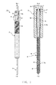
- FIG. 1(a) is a partially cutaway front view showing an example of the glow plug
- FIG. 1(b) is a cross-sectional view of a forward end portion of the glow plug.
- the glow plug 1 includes a tubular metallic shell 2, and a sheath heater 3 attached to the metallic shell 2.
- the metallic shell 2 has an axial hole 4 which extends therethrough in the direction of an axis CL1.
- the metallic shell 2 has a thread portion 5 and a tool engagement portion 6 formed on the outer circumferential surface thereof.
- the thread portion 5 is used for attaching the glow plug 1 to a diesel engine.
- the tool engagement portion 6 has a hexagonal cross section, and a tool such as a torque wrench is engaged with the tool engagement portion 6.
- the sheath heater 3 is constituted by uniting a tube 7 and a center rod 8 in the direction of the axis CL1.
- the tube 7 which is closed at the forward end thereof, is a tube containing iron (Fe) or nickel (Ni) as a main component.
- the rear end of the tube 7 is sealed by an annular rubber member 17 disposed between the tube 7 and the center rod 8.
- a heat generation coil 9 joined to the forward end of the tube 7 and a control coil 10 connected in series to the rear end of the heat generation coil 9 are enclosed in the tube 7, together with insulating powder 11 such as magnesium oxide (MgO) powder.
- insulating powder 11 such as magnesium oxide (MgO) powder.
- the heat generation coil 9 is formed from a resistance heating wire formed of, for example, an Fe - chromium (Cr) - aluminum (Al) alloy.
- the control coil 10 is formed from a resistance heating wire formed of a metallic material which is greater in the temperature coefficient of electrical resistivity than the material of the heat generation coil 9 (e.g., a metallic material which contains Co or Ni as a main component, such as cobalt (Co) - Ni - Fe alloy).
- the control coil 10 increases its electrical resistance upon receipt of heat from the heat generation coil 9 and the control coil 10 itself to thereby control the amount of electric power supplied to the heat generation coil 9 (so-called self-regulation function).
- the sheath heater 3 has a temperature rising characteristic in which after the quick temperature rise at the beginning of energization, the electric power supplied to the heat generation coil 9 is restrained by the action of the control coil 10, whereby the temperature becomes saturated. Namely, through provision of the control coil 10, excessive temperature rise (overshoot) of the heat generation coil 9 is suppressed, while the performance of quickly raising temperature is enhanced.
- the glow plug need not be a glow plug having the above-described self-regulation function, and no problem arises even when a material which is smaller in temperature coefficient than the above-described material (e.g., pure Ni or an Ni alloy containing a small amount of yttrium (Y)) may be properly selected as a material for the control coil 10.
- a material which is smaller in temperature coefficient than the above-described material e.g., pure Ni or an Ni alloy containing a small amount of yttrium (Y)
- Y yttrium
- the tube 7 has a small diameter portion 7a which is formed at the forward end thereof and which accommodates the heat generation coil 9, etc., and a large diameter portion 7b which is formed rearward of the small diameter portion 7a and which has a diameter greater than that of the small diameter portion 7a.
- the small diameter portion 7a and the large diameter portion 7b are formed by swaging or the like.
- This large diameter portion 7b is press-fitted into a small diameter portion 4a of the axial hole 4 of the metallic shell 2, whereby the tube 7 is held in a state in which it projects from the forward end of the metallic shell 2.
- a forward end portion of the center rod 8 is inserted into the tube 7 and is electrically connected to the rear end of the control coil 10.
- the center rod 8 extends through the axial hole 4 of the metallic shell 2.
- the rear end of the center rod 8 projects from the rear end of the metallic shell 2.
- an O-ring 12 formed of rubber or the like, an insulating bushing 13 formed of resin or the like, a press ring 14 for preventing coming off of the insulating bushing 13, and a nut 15 for connecting an electricity supply cable to the center rod 8 are fitted onto the center rod 8 in this order from the forward end side.
- an energization control device 30 for controlling energization of a plurality of glow plugs 1, which is the feature of the present invention, will be described with reference to FIG. 2 .
- the plurality of glow plugs 1 are mounted on an internal combustion engine (not shown in the drawings), and are electrically connected to the earth (ground).
- the energization control device 30 receives an energization signal from an unillustrated external vehicle controller (ECU), etc., and controls the supply of electricity to the glow plugs 1.
- ECU unillustrated external vehicle controller
- the energization control device 30 which operates by using electrical power supplied from a power supply 44 composed of a battery, an alternator, etc., includes a microcomputer 31 including a CPU 32, ROM 33, RAM 34, etc.
- the energization control device 30 has an output terminal A, which serves as a glow plug connection portion for connection with the plurality of glow plugs 1.
- the plurality of glow plugs 1 are connected to this output terminal A through a conduction path 40 such as a conduction harness, an electrode plate, or the like.
- the electric power supplied from the power supply 44 to the plurality of glow plugs 1 through the energization control device 30 passes through a switching section 36 for controlling the effective voltage supplied to the plurality of glow plugs 1, a current obtaining section 37 for obtaining the amount of current supplied to the glow plugs 1 (current value), and a voltage obtaining section 38 for obtaining the voltage of the output terminal A (output voltage).
- the switching section 36 receives the energization signal from the above-mentioned microcomputer 31, and controls, on the basis of this energization signal, the effective voltage of electric power supplied from the power supply 44 to the glow plugs 1.
- the switching section 36 includes an FET (field effect transistor) for ON/OFF control of energization, and a drive circuit which is composed of a plurality of resistors, a transistor, etc. and which drives the FET on the basis of the energization signal.
- the current obtaining section 37 has a shunt resistor B provided, for example, between the switching section 36 and the output terminal A, and obtains the current supplied to the glow plugs 1 by measuring the current flowing through the shunt resistor B.
- the current obtaining section 37 may be realized by an FET having a current detection function which constitutes the switching section 36.
- the voltage obtaining section 38 obtains the voltage applied to the glow plugs 1; i.e., the voltage at the glow plug connection portion A.
- the voltage obtaining section 38 may include unillustrated resistors for voltage division. Notably, when the above-mentioned current value and voltage value are obtained, unillustrated A/D converters which are provided within the microcomputer 31 or are provided separately are used.
- the energization control device 30 includes an energization state determination section 35.
- the energization state determination section 35 is also realized as one function of the microcomputer 31. Accordingly, whereas the energization control device 30 controls the energization of the glow plugs 1 on the basis of the energization signal received from the unillustrated ECU, the energization state determination section 35 determines whether the energization is pre-glow energization or after-glow energization. Also, the energization state determination section 35 receives information representing the rotational speed of the engine, information representing the temperature of cooling water, etc., and determines whether or not the state of the engine is stable.
- the microcomputer 31 Upon receipt of the energization signal from the ECU, etc., the microcomputer 31 outputs a signal for ON/OFF switching to the switching section 36 so as to perform duty control using a PWM control, to thereby control the supply of electric power to the glow plugs 1.
- the energization control device 30 of the present invention determines whether or not wire breakage has occurred in the glow plugs 1, while controlling the supply of electric power to the glow plugs 1.
- the method of detecting wire breakage will be described in detail with reference to FIG. 3 .
- the wire breakage detection in the present invention is performed independently of the supply of electric power to the glow plugs 1 for heat generation, although the state of electric power supply is referred to.
- step S1 When an unillustrated key switch is turned from an OFF position to an ON position at the time of startup of the diesel engine, electric power is supplied to the energization control device 30, whereby the system of the device 30 starts (step S1). Notably, necessary initialization processing may be performed along with step S1.
- the energization control device 30 operates in accordance with an instruction (energization signal) from the ECU.
- the ECU In the case where the engine is in a cold state, for startup of the engine, the ECU outputs an energization signal to the energization control device 30.
- the microcomputer 31 controls the ON/OFF state of the switching section 36 so as to enable the glow plugs 1 to quickly raise temperature for startup of the engine.
- pre-glow energization heating of the glow plugs 1 with the duty ratio set to 100%
- the energization control device 30 obtains the state of the vehicle in step S2.
- the energization control device 30 obtains, as vehicle information, the fact that the engine is in a state before being started; i.e., the engine is stopped.
- the energization control device 30 obtains the voltage and current of the electric power applied to the glow plugs 1.
- the energization control device 30 obtains the voltage from the voltage obtaining section 38 shown in FIG. 2 , and the current from the current obtaining section 37 shown in FIG. 2 (step S3).
- the energization control device 30 determines the state of energization of the glow plugs 1 (step S4). Since pre-glow energization is currently performed, the energization control device 30 performs the processing for the period of pre-glow energization so as to perform wire breakage determination during the period of pre-glow energization (to step S5).
- step S5 the energization control device 30 determines whether or not the pre-glow energization is completed.
- the pre-glow energization is performed until the key switch is returned to the OFF position or the temperatures of the glow plugs 1 reach a temperature suitable for starting the engine. Accordingly, in the case where the temperatures of the glow plugs 1 have not increased sufficiently although the key switch is in the ON position, the energization control device 30 makes a "No" determination in step S5, and repeatedly performs steps S2 to S5 (waits) until the pre-glow energization is completed. Meanwhile, when the temperatures of the glow plugs 1 have increased sufficiently and the pre-glow energization is completed, the energization control device 30 makes a "Yes" determination in step S5, and proceeds to step S6.
- step S6 the energization control device 30 performs wire breakage determination for the glow plugs 1 at the time of completion of the pre-glow energization.
- the wire breakage determination at the time of completion of the pre-glow energization is performed through comparison between a threshold value which is used at the time of completion of the pre-glow energization and the combined resistance of the plurality of glow plugs 1 at the present.
- the combined resistance is calculated from the voltage and current obtained by the voltage obtaining section 38 and the current obtaining section 37, respectively. Setting of the threshold value and the comparison will be described later.
- the state of energization of the glow plugs 1 is switched to temperature-maintaining energization for maintaining the glow plugs 1 at a temperature determined such that the engine can be started when cranking is started.
- the energization control device 30 determines in step S4 that the energization of the glow plugs 1 is the temperature-maintaining energization
- the energization control device 30 proceeds to step S7 so as to perform the wire breakage determination processing for the temperature-maintaining energization.
- the energization control device 30 determines in step S7 whether or not the temperature-maintaining energization is completed.
- the temperature-maintaining energization is performed so as to maintain the heating temperature at the time of completion of the pre-glow energization in the case where cranking is not started (namely, the key switch is not turned to the start position) after the key switch has been turned to the ON position. Accordingly, the temperature-maintaining energization over a long period of time may shorten the life of the glow plugs.
- the energization control device 30 performs a control of ending the temperature-maintaining energization, and entering a vehicle-stopped state which is similar to a state in which the key switch is in the OFF position. Through such a control, the energization control device 30 determines in step S7 whether or not the temperature-maintaining energization is completed. In the case where the energization control device 30 makes a "No" determination in step S7; i.e., determines that it waits the start of cranking, the energization control device 30 proceeds to step S8.
- a period of time e.g. 30 sec
- step S8 the energization control device 30 determines whether or not cranking is started.
- cranking is started (Yes in step S8), the engine starts to rotate, fuel is injected, and intake of air and exhaust of gas are started, whereby the ambient environment of the glow plugs 1 changes. Accordingly, large disturbances act on the glow plugs 1, and, in such a state, accurate determination of wire breakage is difficult.
- wire breakage determination can be performed at the time of cranking or a point in time immediately after the time of cranking (desirably, at a point in time immediately before cranking), because even if disturbances start, the influence of the disturbances on the temperatures of the glow plugs 1 is very small (or such influence does not exist). Meanwhile, in the case where cranking is not started (No in step S8), the energization control device 30 continuously waits for the start of cranking.
- the energization control device 30 makes a further determination when it performs wire breakage determination upon making "Yes" determination in step S8; i.e., upon start of cranking. Namely, in step S9, the energization control device 30 determines whether or not the temperature-maintaining energization has been performed for a predetermined period of time (e.g., 5 sec). The temperature-maintaining energization is started immediately after the completion of the pre-glow energization. However, immediately after the start of the temperature-maintaining energization (within 5 sec in the present example), the influence of the pre-glow energization remains, and the state of the glow plugs 1 cannot be said to be stable.
- a predetermined period of time e.g. 5 sec
- the energization control device 30 makes a "Yes" determination in step S9 only after elapse of a predetermined period of time, and proceeds to step S10 so as to determine whether or not wire breakage has occurred in the glow plugs. Meanwhile, in the case where the energization control device 30 determines that the predetermined period of time has not yet elapsed (No in step S9), the energization control device 30 determines that the chance of performing wire breakage determination during the temperature-maintaining energization is lost. Although not shown in the flowchart of FIG.
- the energization control device 30 may set a flag to indicate that it failed to perform wire breakage determination during the temperature-maintaining energization, and subsequently perform a process of wire breakage determination during the after-glow energization.
- the content of the flag is also set properly.
- step S10 the energization control device 30 performs wire breakage determination at the time of completion of the temperature-maintaining energization.
- the environment of the glow plugs 1 can be said to be most stable. This is because disturbances, such as fuel injection, intake of air and exhaust of gas, etc., do not exist, and energization is performed for a sufficiently long period of time, whereby the temperatures (resistances) of the glow plugs 1 are saturated.
- the after-glow energization will be described before description of wire breakage determination at the time of the after-glow energization.
- the after-glow energization is energization which is performed after the engine is started. Therefore, unlike the pre-glow energization and the temperature-maintaining energization, its chance (the chance of the after-glow energization being performed) is obtained relatively easily because the engine is operating. If a driver quickly performs cranking at the time of the pre-glow energization or at the time of the temperature-maintaining energization, these energization processes are skipped. Meanwhile, the engine has already started its operation, and disturbances are relatively large.
- the energization control device 30 first determines whether or not the temperatures of the glow plugs 1 are saturated (step S11). This is because since the combined resistance of the glow plugs is unstable when the glow plugs 1 are not in a saturated state, it is difficult to perform determination through comparison between the combined resistance and a threshold value. Also, in order to perform accurate wire breakage determination, the energization control device 30 determines whether or not the engine in a stable state (step S12).
- the energization control device 30 determines whether or not the engine is in an operation state suitable for performing wire breakage determination. For example, the energization control device 30 determines whether or not the engine is in an idle state.
- step S13 the energization control device 30 performs wire breakage determination during the after-glow energization. Setting of the threshold value and the comparison will be described later.
- the threshold value which is used for the wire breakage determination at the time of completion of the pre-glow energization is set as follows.
- the threshold value to be compared with the combined resistance of the glow plugs is determined in consideration of the fact that the resistances of the glow plugs are not saturated and are rising. In the above-described step S6, the combined resistance of the glow plugs is compared with this threshold value.
- the threshold value to be compared with the combined resistance of the glow plugs is determined from the saturated resistances.
- the combined resistance of the glow plugs is compared with this threshold value.
- the threshold value used for wire breakage determination be set to a value greater than the threshold value at the time of the pre-glow energization and less than the threshold value at the time of the after-glow energization.
- the threshold value used for the wire breakage determination performed during the temperature-maintaining energization is set to a value which is around the middle between the threshold value at the time of the pre-glow energization and the threshold value at the time of the after-glow energization.
- the above-mentioned threshold values are set, and wire breakage determination is performed in each energization state.
- the energization control device 30 When the energization control device 30 finally determines that wire breakage has occurred, it reports the wire breakage to the ECU, etc. In such a case, the energization control device 30 may make such a report immediately after it determines that wire breakage has occurred in any of the above-mentioned energization states.
- the energization control device 30 may be configured to count the number of times which it determines that wire breakage has occurred (wire breakage count), and make such a report when the counted number reaches a predetermined count number.
- the energization control device 30 may be configured to make such a report only after it determines that wire breakage has occurred in all the energization states.
Landscapes
- Engineering & Computer Science (AREA)
- Chemical & Material Sciences (AREA)
- Combustion & Propulsion (AREA)
- Mechanical Engineering (AREA)
- General Engineering & Computer Science (AREA)
- Combined Controls Of Internal Combustion Engines (AREA)
Applications Claiming Priority (2)
| Application Number | Priority Date | Filing Date | Title |
|---|---|---|---|
| JP2011092481 | 2011-04-18 | ||
| PCT/JP2012/002635 WO2012144191A1 (ja) | 2011-04-18 | 2012-04-17 | グロープラグの通電制御装置 |
Publications (3)
| Publication Number | Publication Date |
|---|---|
| EP2700809A1 true EP2700809A1 (de) | 2014-02-26 |
| EP2700809A4 EP2700809A4 (de) | 2015-03-25 |
| EP2700809B1 EP2700809B1 (de) | 2021-10-20 |
Family
ID=47041325
Family Applications (1)
| Application Number | Title | Priority Date | Filing Date |
|---|---|---|---|
| EP12773846.6A Not-in-force EP2700809B1 (de) | 2011-04-18 | 2012-04-17 | Elektrifizierungssteuerungsvorrichtung für eine zündkerze |
Country Status (4)
| Country | Link |
|---|---|
| EP (1) | EP2700809B1 (de) |
| JP (1) | JP5571797B2 (de) |
| KR (1) | KR101541990B1 (de) |
| WO (1) | WO2012144191A1 (de) |
Cited By (3)
| Publication number | Priority date | Publication date | Assignee | Title |
|---|---|---|---|---|
| EP2947310A1 (de) * | 2014-05-19 | 2015-11-25 | NGK Spark Plug Co., Ltd. | Energieversorgungssteuervorrichtung für eine zündkerze |
| CN106939869A (zh) * | 2015-11-18 | 2017-07-11 | 罗伯特·博世有限公司 | 用于运行数量为n的预热塞的方法和装置 |
| EP3998426A4 (de) * | 2019-10-15 | 2023-07-26 | Chongqing Le-Mark Technology Co., Ltd. | Steuerungsstrategie für heissoberflächenzünder |
Families Citing this family (2)
| Publication number | Priority date | Publication date | Assignee | Title |
|---|---|---|---|---|
| KR20220030652A (ko) * | 2020-09-03 | 2022-03-11 | 현대자동차주식회사 | 엔진의 글로우플러그 단선 검출 방법 |
| CN116950796A (zh) * | 2023-07-18 | 2023-10-27 | 上海夏雪科技有限公司 | 内燃机 |
Family Cites Families (15)
| Publication number | Priority date | Publication date | Assignee | Title |
|---|---|---|---|---|
| US4552102A (en) * | 1981-05-04 | 1985-11-12 | Egle Edward J | System for improving the starting of diesel engines in cold weather |
| JPS5825586A (ja) * | 1981-08-06 | 1983-02-15 | Isuzu Motors Ltd | ディ−ゼルエンジンの始動補助装置 |
| JPS58172472A (ja) * | 1982-04-02 | 1983-10-11 | Nippon Denso Co Ltd | 加熱体の断線検出方法 |
| JPS58176475A (ja) * | 1982-04-09 | 1983-10-15 | Isuzu Motors Ltd | 予熱栓断線検出装置 |
| JPS6153462A (ja) * | 1984-08-21 | 1986-03-17 | Nippon Denso Co Ltd | 加熱体の断線検出方法 |
| US4858576A (en) * | 1986-11-28 | 1989-08-22 | Caterpillar Inc. | Glow plug alternator control |
| JPH02199274A (ja) | 1989-01-27 | 1990-08-07 | Fujitsu Ten Ltd | グロープラグ電圧検知方法 |
| JPH03105043A (ja) * | 1989-09-14 | 1991-05-01 | Mazda Motor Corp | ディーゼルエンジンのグロープラグ通電制御装置 |
| JP3952562B2 (ja) * | 1997-12-18 | 2007-08-01 | いすゞ自動車株式会社 | グロープラグの断線検出システム |
| JP2002013461A (ja) * | 2000-06-28 | 2002-01-18 | Isuzu Motors Ltd | グロープラグ故障診断装置および方法 |
| JP4064295B2 (ja) * | 2002-05-14 | 2008-03-19 | 日本特殊陶業株式会社 | グロープラグの制御装置 |
| JP2004190659A (ja) | 2002-11-28 | 2004-07-08 | Ngk Spark Plug Co Ltd | グロープラグの取付け構造、グロープラグ及びソケット端子付き配線コード |
| JP5475219B2 (ja) * | 2006-03-29 | 2014-04-16 | 日本特殊陶業株式会社 | グロープラグ通電制御装置 |
| JP4956486B2 (ja) * | 2008-05-30 | 2012-06-20 | 日本特殊陶業株式会社 | グロープラグ通電制御装置及びグロープラグ通電制御システム |
| JP2010085058A (ja) * | 2008-10-02 | 2010-04-15 | Ngk Spark Plug Co Ltd | グロープラグ短絡検知装置及び発熱システム |
-
2012
- 2012-04-17 WO PCT/JP2012/002635 patent/WO2012144191A1/ja not_active Ceased
- 2012-04-17 KR KR1020137029489A patent/KR101541990B1/ko active Active
- 2012-04-17 JP JP2012535271A patent/JP5571797B2/ja not_active Expired - Fee Related
- 2012-04-17 EP EP12773846.6A patent/EP2700809B1/de not_active Not-in-force
Cited By (3)
| Publication number | Priority date | Publication date | Assignee | Title |
|---|---|---|---|---|
| EP2947310A1 (de) * | 2014-05-19 | 2015-11-25 | NGK Spark Plug Co., Ltd. | Energieversorgungssteuervorrichtung für eine zündkerze |
| CN106939869A (zh) * | 2015-11-18 | 2017-07-11 | 罗伯特·博世有限公司 | 用于运行数量为n的预热塞的方法和装置 |
| EP3998426A4 (de) * | 2019-10-15 | 2023-07-26 | Chongqing Le-Mark Technology Co., Ltd. | Steuerungsstrategie für heissoberflächenzünder |
Also Published As
| Publication number | Publication date |
|---|---|
| EP2700809A4 (de) | 2015-03-25 |
| JPWO2012144191A1 (ja) | 2014-07-28 |
| WO2012144191A1 (ja) | 2012-10-26 |
| JP5571797B2 (ja) | 2014-08-13 |
| KR101541990B1 (ko) | 2015-08-05 |
| KR20130140865A (ko) | 2013-12-24 |
| EP2700809B1 (de) | 2021-10-20 |
Similar Documents
| Publication | Publication Date | Title |
|---|---|---|
| US9074575B2 (en) | Energization control apparatus for glow plug | |
| US8847118B2 (en) | Energization control apparatus for glow plug | |
| EP2700809B1 (de) | Elektrifizierungssteuerungsvorrichtung für eine zündkerze | |
| US8775051B2 (en) | Apparatus for diagnosing temperature state of carrier of catalyst converter | |
| US7711498B2 (en) | Glow plug degradation determination device | |
| US8217310B2 (en) | Glow plug electrification control apparatus and glow plug electrification control system | |
| US7487753B2 (en) | Glow plug energization control apparatus and method | |
| US8583344B2 (en) | Method for controlling glow plugs in a diesel engine, particularly for motor-vehicles | |
| KR101188072B1 (ko) | 글로 플러그의 통전 제어장치 및 발열 시스템 | |
| US5752493A (en) | Apparatus for controlling a heater for heating an air-fuel ratio sensor | |
| JP2010175116A (ja) | グロープラグの通電制御装置及びその制御方法 | |
| JP2009250182A (ja) | 発熱体制御装置 | |
| JP6833264B2 (ja) | 内燃機関の制御装置 | |
| KR20150018379A (ko) | 예열플러그 교체 감지방법 및 예열플러그 제어장치 | |
| US11248550B2 (en) | Internal combustion engine control device | |
| JP4442614B2 (ja) | グロープラグの異常診断装置 | |
| JP5988805B2 (ja) | 内燃機関の制御装置 | |
| JPH1182271A (ja) | ディーゼルエンジンの異常検出装置 | |
| JP5537280B2 (ja) | グロープラグの通電制御装置 | |
| KR101642127B1 (ko) | 내구 수명 보강을 위한 고온 발열이 가능한 글로우 플러그, 이를 제어하는 제어 유닛 및 제어 유닛의 제어 방법 | |
| BR102019027485B1 (pt) | Vela de incandescência ou aquecimento para motores de combustão interna | |
| CN110582629A (zh) | 内燃机控制装置 | |
| JP2010002192A (ja) | ガスセンサのヒータ劣化検出装置 |
Legal Events
| Date | Code | Title | Description |
|---|---|---|---|
| PUAI | Public reference made under article 153(3) epc to a published international application that has entered the european phase |
Free format text: ORIGINAL CODE: 0009012 |
|
| 17P | Request for examination filed |
Effective date: 20131004 |
|
| AK | Designated contracting states |
Kind code of ref document: A1 Designated state(s): AL AT BE BG CH CY CZ DE DK EE ES FI FR GB GR HR HU IE IS IT LI LT LU LV MC MK MT NL NO PL PT RO RS SE SI SK SM TR |
|
| DAX | Request for extension of the european patent (deleted) | ||
| A4 | Supplementary search report drawn up and despatched |
Effective date: 20150220 |
|
| RIC1 | Information provided on ipc code assigned before grant |
Ipc: F02P 19/02 20060101AFI20150216BHEP |
|
| GRAP | Despatch of communication of intention to grant a patent |
Free format text: ORIGINAL CODE: EPIDOSNIGR1 |
|
| STAA | Information on the status of an ep patent application or granted ep patent |
Free format text: STATUS: GRANT OF PATENT IS INTENDED |
|
| INTG | Intention to grant announced |
Effective date: 20210526 |
|
| GRAS | Grant fee paid |
Free format text: ORIGINAL CODE: EPIDOSNIGR3 |
|
| GRAA | (expected) grant |
Free format text: ORIGINAL CODE: 0009210 |
|
| STAA | Information on the status of an ep patent application or granted ep patent |
Free format text: STATUS: THE PATENT HAS BEEN GRANTED |
|
| AK | Designated contracting states |
Kind code of ref document: B1 Designated state(s): AL AT BE BG CH CY CZ DE DK EE ES FI FR GB GR HR HU IE IS IT LI LT LU LV MC MK MT NL NO PL PT RO RS SE SI SK SM TR |
|
| REG | Reference to a national code |
Ref country code: GB Ref legal event code: FG4D |
|
| REG | Reference to a national code |
Ref country code: CH Ref legal event code: EP |
|
| REG | Reference to a national code |
Ref country code: DE Ref legal event code: R096 Ref document number: 602012076960 Country of ref document: DE |
|
| REG | Reference to a national code |
Ref country code: IE Ref legal event code: FG4D |
|
| REG | Reference to a national code |
Ref country code: AT Ref legal event code: REF Ref document number: 1440149 Country of ref document: AT Kind code of ref document: T Effective date: 20211115 |
|
| REG | Reference to a national code |
Ref country code: LT Ref legal event code: MG9D |
|
| REG | Reference to a national code |
Ref country code: NL Ref legal event code: MP Effective date: 20211020 |
|
| REG | Reference to a national code |
Ref country code: AT Ref legal event code: MK05 Ref document number: 1440149 Country of ref document: AT Kind code of ref document: T Effective date: 20211020 |
|
| PG25 | Lapsed in a contracting state [announced via postgrant information from national office to epo] |
Ref country code: RS Free format text: LAPSE BECAUSE OF FAILURE TO SUBMIT A TRANSLATION OF THE DESCRIPTION OR TO PAY THE FEE WITHIN THE PRESCRIBED TIME-LIMIT Effective date: 20211020 Ref country code: LT Free format text: LAPSE BECAUSE OF FAILURE TO SUBMIT A TRANSLATION OF THE DESCRIPTION OR TO PAY THE FEE WITHIN THE PRESCRIBED TIME-LIMIT Effective date: 20211020 Ref country code: FI Free format text: LAPSE BECAUSE OF FAILURE TO SUBMIT A TRANSLATION OF THE DESCRIPTION OR TO PAY THE FEE WITHIN THE PRESCRIBED TIME-LIMIT Effective date: 20211020 Ref country code: BG Free format text: LAPSE BECAUSE OF FAILURE TO SUBMIT A TRANSLATION OF THE DESCRIPTION OR TO PAY THE FEE WITHIN THE PRESCRIBED TIME-LIMIT Effective date: 20220120 Ref country code: AT Free format text: LAPSE BECAUSE OF FAILURE TO SUBMIT A TRANSLATION OF THE DESCRIPTION OR TO PAY THE FEE WITHIN THE PRESCRIBED TIME-LIMIT Effective date: 20211020 |
|
| PG25 | Lapsed in a contracting state [announced via postgrant information from national office to epo] |
Ref country code: IS Free format text: LAPSE BECAUSE OF FAILURE TO SUBMIT A TRANSLATION OF THE DESCRIPTION OR TO PAY THE FEE WITHIN THE PRESCRIBED TIME-LIMIT Effective date: 20220220 Ref country code: SE Free format text: LAPSE BECAUSE OF FAILURE TO SUBMIT A TRANSLATION OF THE DESCRIPTION OR TO PAY THE FEE WITHIN THE PRESCRIBED TIME-LIMIT Effective date: 20211020 Ref country code: PT Free format text: LAPSE BECAUSE OF FAILURE TO SUBMIT A TRANSLATION OF THE DESCRIPTION OR TO PAY THE FEE WITHIN THE PRESCRIBED TIME-LIMIT Effective date: 20220221 Ref country code: PL Free format text: LAPSE BECAUSE OF FAILURE TO SUBMIT A TRANSLATION OF THE DESCRIPTION OR TO PAY THE FEE WITHIN THE PRESCRIBED TIME-LIMIT Effective date: 20211020 Ref country code: NO Free format text: LAPSE BECAUSE OF FAILURE TO SUBMIT A TRANSLATION OF THE DESCRIPTION OR TO PAY THE FEE WITHIN THE PRESCRIBED TIME-LIMIT Effective date: 20220120 Ref country code: NL Free format text: LAPSE BECAUSE OF FAILURE TO SUBMIT A TRANSLATION OF THE DESCRIPTION OR TO PAY THE FEE WITHIN THE PRESCRIBED TIME-LIMIT Effective date: 20211020 Ref country code: LV Free format text: LAPSE BECAUSE OF FAILURE TO SUBMIT A TRANSLATION OF THE DESCRIPTION OR TO PAY THE FEE WITHIN THE PRESCRIBED TIME-LIMIT Effective date: 20211020 Ref country code: HR Free format text: LAPSE BECAUSE OF FAILURE TO SUBMIT A TRANSLATION OF THE DESCRIPTION OR TO PAY THE FEE WITHIN THE PRESCRIBED TIME-LIMIT Effective date: 20211020 Ref country code: GR Free format text: LAPSE BECAUSE OF FAILURE TO SUBMIT A TRANSLATION OF THE DESCRIPTION OR TO PAY THE FEE WITHIN THE PRESCRIBED TIME-LIMIT Effective date: 20220121 Ref country code: ES Free format text: LAPSE BECAUSE OF FAILURE TO SUBMIT A TRANSLATION OF THE DESCRIPTION OR TO PAY THE FEE WITHIN THE PRESCRIBED TIME-LIMIT Effective date: 20211020 |
|
| REG | Reference to a national code |
Ref country code: DE Ref legal event code: R097 Ref document number: 602012076960 Country of ref document: DE |
|
| PG25 | Lapsed in a contracting state [announced via postgrant information from national office to epo] |
Ref country code: SM Free format text: LAPSE BECAUSE OF FAILURE TO SUBMIT A TRANSLATION OF THE DESCRIPTION OR TO PAY THE FEE WITHIN THE PRESCRIBED TIME-LIMIT Effective date: 20211020 Ref country code: SK Free format text: LAPSE BECAUSE OF FAILURE TO SUBMIT A TRANSLATION OF THE DESCRIPTION OR TO PAY THE FEE WITHIN THE PRESCRIBED TIME-LIMIT Effective date: 20211020 Ref country code: RO Free format text: LAPSE BECAUSE OF FAILURE TO SUBMIT A TRANSLATION OF THE DESCRIPTION OR TO PAY THE FEE WITHIN THE PRESCRIBED TIME-LIMIT Effective date: 20211020 Ref country code: EE Free format text: LAPSE BECAUSE OF FAILURE TO SUBMIT A TRANSLATION OF THE DESCRIPTION OR TO PAY THE FEE WITHIN THE PRESCRIBED TIME-LIMIT Effective date: 20211020 Ref country code: DK Free format text: LAPSE BECAUSE OF FAILURE TO SUBMIT A TRANSLATION OF THE DESCRIPTION OR TO PAY THE FEE WITHIN THE PRESCRIBED TIME-LIMIT Effective date: 20211020 Ref country code: CZ Free format text: LAPSE BECAUSE OF FAILURE TO SUBMIT A TRANSLATION OF THE DESCRIPTION OR TO PAY THE FEE WITHIN THE PRESCRIBED TIME-LIMIT Effective date: 20211020 |
|
| PLBE | No opposition filed within time limit |
Free format text: ORIGINAL CODE: 0009261 |
|
| STAA | Information on the status of an ep patent application or granted ep patent |
Free format text: STATUS: NO OPPOSITION FILED WITHIN TIME LIMIT |
|
| 26N | No opposition filed |
Effective date: 20220721 |
|
| PG25 | Lapsed in a contracting state [announced via postgrant information from national office to epo] |
Ref country code: AL Free format text: LAPSE BECAUSE OF FAILURE TO SUBMIT A TRANSLATION OF THE DESCRIPTION OR TO PAY THE FEE WITHIN THE PRESCRIBED TIME-LIMIT Effective date: 20211020 |
|
| PG25 | Lapsed in a contracting state [announced via postgrant information from national office to epo] |
Ref country code: SI Free format text: LAPSE BECAUSE OF FAILURE TO SUBMIT A TRANSLATION OF THE DESCRIPTION OR TO PAY THE FEE WITHIN THE PRESCRIBED TIME-LIMIT Effective date: 20211020 |
|
| REG | Reference to a national code |
Ref country code: CH Ref legal event code: PL |
|
| GBPC | Gb: european patent ceased through non-payment of renewal fee |
Effective date: 20220417 |
|
| REG | Reference to a national code |
Ref country code: BE Ref legal event code: MM Effective date: 20220430 |
|
| PG25 | Lapsed in a contracting state [announced via postgrant information from national office to epo] |
Ref country code: MC Free format text: LAPSE BECAUSE OF FAILURE TO SUBMIT A TRANSLATION OF THE DESCRIPTION OR TO PAY THE FEE WITHIN THE PRESCRIBED TIME-LIMIT Effective date: 20211020 Ref country code: LU Free format text: LAPSE BECAUSE OF NON-PAYMENT OF DUE FEES Effective date: 20220417 Ref country code: LI Free format text: LAPSE BECAUSE OF NON-PAYMENT OF DUE FEES Effective date: 20220430 Ref country code: GB Free format text: LAPSE BECAUSE OF NON-PAYMENT OF DUE FEES Effective date: 20220417 Ref country code: CH Free format text: LAPSE BECAUSE OF NON-PAYMENT OF DUE FEES Effective date: 20220430 |
|
| PG25 | Lapsed in a contracting state [announced via postgrant information from national office to epo] |
Ref country code: BE Free format text: LAPSE BECAUSE OF NON-PAYMENT OF DUE FEES Effective date: 20220430 |
|
| PG25 | Lapsed in a contracting state [announced via postgrant information from national office to epo] |
Ref country code: IE Free format text: LAPSE BECAUSE OF NON-PAYMENT OF DUE FEES Effective date: 20220417 |
|
| PGFP | Annual fee paid to national office [announced via postgrant information from national office to epo] |
Ref country code: FR Payment date: 20230309 Year of fee payment: 12 |
|
| PG25 | Lapsed in a contracting state [announced via postgrant information from national office to epo] |
Ref country code: IT Free format text: LAPSE BECAUSE OF FAILURE TO SUBMIT A TRANSLATION OF THE DESCRIPTION OR TO PAY THE FEE WITHIN THE PRESCRIBED TIME-LIMIT Effective date: 20211020 |
|
| PGFP | Annual fee paid to national office [announced via postgrant information from national office to epo] |
Ref country code: DE Payment date: 20230228 Year of fee payment: 12 |
|
| REG | Reference to a national code |
Ref country code: DE Ref legal event code: R081 Ref document number: 602012076960 Country of ref document: DE Owner name: NITERRA CO., LTD., NAGOYA-SHI, JP Free format text: FORMER OWNER: NGK SPARK PLUG CO., LTD., NAGOYA-SHI, AICHI, JP |
|
| PG25 | Lapsed in a contracting state [announced via postgrant information from national office to epo] |
Ref country code: HU Free format text: LAPSE BECAUSE OF FAILURE TO SUBMIT A TRANSLATION OF THE DESCRIPTION OR TO PAY THE FEE WITHIN THE PRESCRIBED TIME-LIMIT; INVALID AB INITIO Effective date: 20120417 |
|
| PG25 | Lapsed in a contracting state [announced via postgrant information from national office to epo] |
Ref country code: MK Free format text: LAPSE BECAUSE OF FAILURE TO SUBMIT A TRANSLATION OF THE DESCRIPTION OR TO PAY THE FEE WITHIN THE PRESCRIBED TIME-LIMIT Effective date: 20211020 Ref country code: CY Free format text: LAPSE BECAUSE OF FAILURE TO SUBMIT A TRANSLATION OF THE DESCRIPTION OR TO PAY THE FEE WITHIN THE PRESCRIBED TIME-LIMIT Effective date: 20211020 |
|
| PG25 | Lapsed in a contracting state [announced via postgrant information from national office to epo] |
Ref country code: TR Free format text: LAPSE BECAUSE OF FAILURE TO SUBMIT A TRANSLATION OF THE DESCRIPTION OR TO PAY THE FEE WITHIN THE PRESCRIBED TIME-LIMIT Effective date: 20211020 |
|
| PG25 | Lapsed in a contracting state [announced via postgrant information from national office to epo] |
Ref country code: MT Free format text: LAPSE BECAUSE OF FAILURE TO SUBMIT A TRANSLATION OF THE DESCRIPTION OR TO PAY THE FEE WITHIN THE PRESCRIBED TIME-LIMIT Effective date: 20211020 |
|
| REG | Reference to a national code |
Ref country code: DE Ref legal event code: R119 Ref document number: 602012076960 Country of ref document: DE |
|
| PG25 | Lapsed in a contracting state [announced via postgrant information from national office to epo] |
Ref country code: DE Free format text: LAPSE BECAUSE OF NON-PAYMENT OF DUE FEES Effective date: 20241105 |
|
| PG25 | Lapsed in a contracting state [announced via postgrant information from national office to epo] |
Ref country code: FR Free format text: LAPSE BECAUSE OF NON-PAYMENT OF DUE FEES Effective date: 20240430 |
|
| PG25 | Lapsed in a contracting state [announced via postgrant information from national office to epo] |
Ref country code: FR Free format text: LAPSE BECAUSE OF NON-PAYMENT OF DUE FEES Effective date: 20240430 Ref country code: DE Free format text: LAPSE BECAUSE OF NON-PAYMENT OF DUE FEES Effective date: 20241105 |