EP2700899A2 - Dispositif d'accélération pour l'accélération d'un projectile - Google Patents
Dispositif d'accélération pour l'accélération d'un projectile Download PDFInfo
- Publication number
- EP2700899A2 EP2700899A2 EP13180830.5A EP13180830A EP2700899A2 EP 2700899 A2 EP2700899 A2 EP 2700899A2 EP 13180830 A EP13180830 A EP 13180830A EP 2700899 A2 EP2700899 A2 EP 2700899A2
- Authority
- EP
- European Patent Office
- Prior art keywords
- acceleration
- sabot
- projectile
- tube
- receptacle
- Prior art date
- Legal status (The legal status is an assumption and is not a legal conclusion. Google has not performed a legal analysis and makes no representation as to the accuracy of the status listed.)
- Granted
Links
- 230000001133 acceleration Effects 0.000 title claims abstract description 160
- 229910052751 metal Inorganic materials 0.000 claims description 17
- 239000002184 metal Substances 0.000 claims description 17
- 239000004033 plastic Substances 0.000 claims description 4
- 239000000463 material Substances 0.000 claims description 3
- 239000006261 foam material Substances 0.000 claims description 2
- 230000006835 compression Effects 0.000 abstract 1
- 238000007906 compression Methods 0.000 abstract 1
- 239000007789 gas Substances 0.000 description 33
- 238000000034 method Methods 0.000 description 5
- 239000003380 propellant Substances 0.000 description 4
- 239000004793 Polystyrene Substances 0.000 description 3
- 229910052782 aluminium Inorganic materials 0.000 description 3
- XAGFODPZIPBFFR-UHFFFAOYSA-N aluminium Chemical compound [Al] XAGFODPZIPBFFR-UHFFFAOYSA-N 0.000 description 3
- 230000001066 destructive effect Effects 0.000 description 3
- 239000012634 fragment Substances 0.000 description 3
- 229920002223 polystyrene Polymers 0.000 description 3
- 239000006260 foam Substances 0.000 description 2
- 238000011835 investigation Methods 0.000 description 2
- 229910001092 metal group alloy Inorganic materials 0.000 description 2
- 239000011248 coating agent Substances 0.000 description 1
- 238000000576 coating method Methods 0.000 description 1
- 230000001419 dependent effect Effects 0.000 description 1
- 239000004744 fabric Substances 0.000 description 1
- 230000002349 favourable effect Effects 0.000 description 1
- 238000010304 firing Methods 0.000 description 1
- 238000013467 fragmentation Methods 0.000 description 1
- 238000006062 fragmentation reaction Methods 0.000 description 1
- 230000001788 irregular Effects 0.000 description 1
- 230000014759 maintenance of location Effects 0.000 description 1
- 238000004519 manufacturing process Methods 0.000 description 1
- 239000007769 metal material Substances 0.000 description 1
- 239000000203 mixture Substances 0.000 description 1
- 230000004048 modification Effects 0.000 description 1
- 238000012986 modification Methods 0.000 description 1
- 229920000642 polymer Polymers 0.000 description 1
- 230000000717 retained effect Effects 0.000 description 1
- 239000007787 solid Substances 0.000 description 1
- 230000001360 synchronised effect Effects 0.000 description 1
- 238000011144 upstream manufacturing Methods 0.000 description 1
Images


Classifications
-
- F—MECHANICAL ENGINEERING; LIGHTING; HEATING; WEAPONS; BLASTING
- F42—AMMUNITION; BLASTING
- F42B—EXPLOSIVE CHARGES, e.g. FOR BLASTING, FIREWORKS, AMMUNITION
- F42B14/00—Projectiles or missiles characterised by arrangements for guiding or sealing them inside barrels, or for lubricating or cleaning barrels
- F42B14/06—Sub-calibre projectiles having sabots; Sabots therefor
- F42B14/064—Sabots enclosing the rear end of a kinetic energy projectile, i.e. having a closed disk shaped obturator base and petals extending forward from said base
-
- F—MECHANICAL ENGINEERING; LIGHTING; HEATING; WEAPONS; BLASTING
- F41—WEAPONS
- F41A—FUNCTIONAL FEATURES OR DETAILS COMMON TO BOTH SMALLARMS AND ORDNANCE, e.g. CANNONS; MOUNTINGS FOR SMALLARMS OR ORDNANCE
- F41A21/00—Barrels; Gun tubes; Muzzle attachments; Barrel mounting means
- F41A21/16—Barrels or gun tubes characterised by the shape of the bore
-
- F—MECHANICAL ENGINEERING; LIGHTING; HEATING; WEAPONS; BLASTING
- F41—WEAPONS
- F41A—FUNCTIONAL FEATURES OR DETAILS COMMON TO BOTH SMALLARMS AND ORDNANCE, e.g. CANNONS; MOUNTINGS FOR SMALLARMS OR ORDNANCE
- F41A21/00—Barrels; Gun tubes; Muzzle attachments; Barrel mounting means
- F41A21/46—Barrels having means for separating sabots from projectiles
-
- F—MECHANICAL ENGINEERING; LIGHTING; HEATING; WEAPONS; BLASTING
- F41—WEAPONS
- F41B—WEAPONS FOR PROJECTING MISSILES WITHOUT USE OF EXPLOSIVE OR COMBUSTIBLE PROPELLANT CHARGE; WEAPONS NOT OTHERWISE PROVIDED FOR
- F41B11/00—Compressed-gas guns, e.g. air guns; Steam guns
- F41B11/60—Compressed-gas guns, e.g. air guns; Steam guns characterised by the supply of compressed gas
- F41B11/62—Compressed-gas guns, e.g. air guns; Steam guns characterised by the supply of compressed gas with pressure supplied by a gas cartridge
-
- F—MECHANICAL ENGINEERING; LIGHTING; HEATING; WEAPONS; BLASTING
- F41—WEAPONS
- F41B—WEAPONS FOR PROJECTING MISSILES WITHOUT USE OF EXPLOSIVE OR COMBUSTIBLE PROPELLANT CHARGE; WEAPONS NOT OTHERWISE PROVIDED FOR
- F41B11/00—Compressed-gas guns, e.g. air guns; Steam guns
- F41B11/70—Details not provided for in F41B11/50 or F41B11/60
- F41B11/72—Valves; Arrangement of valves
- F41B11/723—Valves; Arrangement of valves for controlling gas pressure for firing the projectile only
Definitions
- the invention relates to an acceleration device for accelerating a projectile with an acceleration tube and a sabot.
- projectiles are accelerated in an acceleration tube and fired at high speed onto a component or target object to be tested.
- the projectiles in the acceleration tube are usually taken up in a so-called sabot and accelerated by gas pressure, which is set in a reservoir depending on the desired target speed and reproducibly applied to the projectile or the sabot via a valve.
- the present invention is therefore based on the object to provide an improved acceleration device with which non-rotationally symmetrical projectiles can be fired.
- the acceleration device for accelerating a projectile comprises an acceleration tube having a longitudinal axis defining an acceleration direction and a sabot having a projectile receiver at its forward end in the direction of acceleration for receiving a projectile.
- the accelerator tube is provided with a sabot stopper for stopping the sabot in its accelerating direction front end portion and coupled with a pressure generating device at its rear end in the accelerating direction.
- the projectile receiver of the sabot for picking up a projectile with a polygonal cross-sectional area is configured transversely to the acceleration direction, the acceleration tube has a polygonal inner lateral surface and the sabot has a polygonal outer lateral surface such that the sabot can slide along the inner circumferential surface of the acceleration tube.
- the sabot of the accelerator device has a special projectile mount, which is designed to receive a projectile with a polygonal cross-sectional area transversely to the direction of acceleration. With the aid of this sabot, non-rotationally symmetrical projectiles with a polygonal cross-sectional area can thus be shot against rotation.
- the acceleration tube has a polygonal inner lateral surface and the sabot has a polygonal outer lateral surface in such a way that the sabot can slide along the inner lateral surface of the acceleration tube.
- the geometries of the sabot and the acceleration tube are also adapted to the (non-round) cross-sectional shape of the projectile to be fired. It is therefore possible to use a sabot and an acceleration tube each with the smallest possible cross-sectional area for accelerating a non-rotationally symmetrical projectile. As a result, lower gas pressures are needed to accelerate the projectile or higher projectile velocities can be achieved with the same gas pressure or more massive projectiles can be fired.
- By adapting the geometries of acceleration tube and sabot to a non-rotationally symmetrical projectile also more accurate and better reproducible speeds, attitudes and orientations for such a projectile can be ensured.
- polygonal cross-sectional area and "polygonal inner / outer lateral surface” in this context include regular and irregular polygons (polygons), equilateral polygons and polygons with different lengths edges, polygonal equations and polygons with different internal angles, polygons with pointed and with rounded corners, polygons with rectilinear and with convex or concave curved edges.
- the most preferred polygons in this context include squares and rectangles.
- the outer surface of the acceleration tube is basically arbitrary.
- the outer circumferential surface of the acceleration tube is polygonal and corresponds to the inner circumferential surface, so that the acceleration tube has a substantially uniform wall thickness over its entire circumference.
- the acceleration tube preferably has a substantially uniform wall thickness over its entire length.
- the acceleration tube preferably has a substantially uniform cross-sectional shape over its entire length.
- the "projectile receptacle” is a component of the sabot or a separate component which is fixedly or detachably connected to the sabot.
- the projectile mount is configured to at least partially receive a desired projectile and to hold it in position during acceleration in the accelerator tube.
- the projectile is easily clamped or fixed in the projectile receptacle, optionally along the entire circumference transversely to the direction of acceleration or only in sections, to the projectile during the Accelerate exactly to position and to achieve a clean detachment of the projectile from the sabot when hitting themaschineLitestopper.
- the projectile receptacle preferably has a recess in which the projectile can be arranged. The depth of the recess in the direction of acceleration may be less than, equal to or greater than the length of the projectile in the direction of acceleration.
- any type of device is to be understood, which is used between projectile and propellant and is suitable to seal the accelerating tube against the propellant gases and to separate the projectile from the propellant gases.
- the geometry of the outer surface of the sabot is accordingly adapted to the geometry of the inner circumferential surface of the acceleration tube.
- the aforementioned lateral surfaces are designed so that the sabot in the acceleration tube in the direction of acceleration can be moved by the gas pressure of the propellant gases.
- the outer surface of the sabot may extend over its entire length, but it is preferably provided only in sections in the direction of acceleration on the sabot, so that the sliding contact surfaces between the sabot and the acceleration tube are as small as possible.
- the inner lateral surface of the acceleration tube and / or the outer lateral surface of the sabot are preferably machined and / or coated such that the frictional resistance between the two lateral surfaces is as small as possible.
- the sabot is formed in one piece or in several parts. In one embodiment of the invention, the sabot is composed of several layers that are stacked in the direction of acceleration and firmly joined together, preferably glued, vulcanized, welded or the like.
- the sabot is a solid body or hollow designed.
- the sabot has a projectile mount to guide a projectile at least partially received therein in the desired orientation or attitude.
- the projectile recording is adapted for this purpose to the shape, dimension and attitude of the projectile to be fired or
- pressure generating device in this context, any type of device to be understood, which is suitable to build up in the acceleration direction behind the sabot in the acceleration tube pressure that accelerates the sabot with the projectile in the acceleration tube in the direction of acceleration.
- This is preferably a gas pressure which is introduced from corresponding compressed gas containers via valves in the acceleration tube.
- the "sabot stopper” is a stop in the front end region of the acceleration tube, which retains the accelerated sabot and the projectile recording in the acceleration tube during the acceleration process of the projectile and the projectile due to its inertia further fly out of the front end of the acceleration tube.
- the sabot stopper is provided in full or only in sections on or along the inner circumferential surface of the acceleration tube.
- the sabot stopper is preferably designed for nondestructive or destructive stopping of the sabot.
- the sabot stopper is preferably fixedly connected to the acceleration tube, preferably screwed or welded thereto.
- the sabot stopper is preferably in the direction of acceleration of the projectile substantially at the level of the open front end side of the acceleration tube, upstream of the front end side of the acceleration tube and thus inside the acceleration tube or the front end side of the acceleration tube and thus arranged outside of the acceleration tube.
- the passage opening of the sabot stopper is preferably made polygonal according to the projectile to be fired.
- the polygonal inner circumferential surface of the acceleration tube is configured substantially rectangular or square. These rectangular and square cross-sectional shapes are particularly easy to manufacture. The same applies of course to the polygonal outer lateral surface of the sabot.
- the acceleration tube is releasably connected to the pressure generating device.
- the acceleration device can thus be adapted in a simple manner to the respective projectile to be fired, without having to provide a separate acceleration device for each projectile geometry.
- the sabot is preferably also replaced and replaced by a sabot adapted to the projectile to be fired.
- the projectile receptacle is detachably connected to the sabot.
- the projectile mount can preferably be replaced after each acceleration operation or after a few acceleration events, if it is damaged by the stop against the sabot stopper.
- the sabot can also be easily adapted to the particular projectile to be fired without having to provide a separate sabot for each projectile geometry including projectile recording.
- At least one metal plate is arranged between the projectile receptacle and the sabot.
- the projectile received in the projectile receptacle can thus be supported in particular against this metal plate during the acceleration process. In this way it can be prevented that the projectile presses during the acceleration process in the acceleration tube in the sabot and possibly even deformed.
- the at least one metal plate is preferably dimensionally stable.
- a plate made of a light metal, preferably aluminum, or a light metal alloy is used for the at least one metal plate.
- a metal plate made of light metal increases the weight of the sabot only slightly, so that the mass to be accelerated by this measure is not excessively increased.
- the sabot where the sabot is to be more accelerated to achieve higher speeds of the projectile, can also be dispensed with such a metal plate. There is then the possibility of stopping the sabot by the appropriately designed sabot stopper in a destructive manner in the end region of the acceleration tube and thereby to produce smaller and lower-mass fragments of the sabot.
- the sabot and / or the projectile receptacle are essentially formed from a plastic material, in particular a hard foam material.
- the plastic material is preferably a polymer, preferably polystyrene.
- the sabot and / or the projectile mount can be made substantially of a metallic material, particularly a light metal or a light metal alloy.
- the pressure generating device has at least two valves, ie, two, three, four or more valves for introducing a gas into a drive chamber formed in the acceleration tube in the direction of acceleration behind the sabot. These at least two valves can be actuated by a control device essentially synchronously with one another.
- a higher gas pressure and / or a gas pressure can be introduced into the drive chamber in a shorter time. As a result, higher target speeds and / or target speeds can be achieved with higher reproducibility for the projectile.
- projectile speeds in the range from about 20 m / s to about 250 m / s and more can be achieved, in particular in the case of non-metallic slosh mirrors of even 500 m / s and more.
- larger and heavier projectiles can be accelerated, preferably with cross-sectional areas of up to 500 mm ⁇ 500 mm and more and / or with masses of up to about 10 kg and more.
- the projectile receptacle is configured at least partially deformable, so that it at least partially deforms when striking against themaschineLitestopper to release the recorded projectile.
- the partial deformation of the projectile recording is preferably carried out by a plastic deformation, pivoting or folding away of sections, a breaking away of sections and the like.
- the invention also relates to a sabot which can be used in particular for an acceleration device of the invention described above.
- the sabot according to the invention has a polygonal outer lateral surface and a projectile receptacle at its front end in the direction of acceleration for receiving a projectile having a polygonal cross-sectional area.
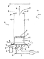
- Fig. 1 an acceleration device for accelerating non-rotationally symmetrical projectiles is shown in a highly simplified manner.
- This accelerator device can be used, for example, to study structure components in the aerospace industry, without it being restricted to this application.
- the acceleration device 10 has, in particular, an acceleration tube 12 whose longitudinal axis defines an acceleration direction 14.
- a projectile 16 can be accelerated in the direction of acceleration 14 by means of a sabot 18.
- the acceleration tube 12 has a rear end 20 and a front outlet 22 open in the acceleration direction 14.
- the cross-sectional shapes of the inner circumferential surface 24 of the acceleration tube 12 and the outer circumferential surface 26 of the sabot 18 are each configured polygonal, preferably substantially rectangular.
- the geometries of the inner circumferential surface 24 of the acceleration tube 12 and the outer circumferential surface 26 of the sabot 18 are selected so that the sabot 18 along the inner circumferential surface 24 of the acceleration tube 12 can slide.
- an inwardly projecting stop 28 (full or in sections).
- the stop 28 is screwed or welded to the accelerating tube 12, for example.
- the sabot 18 can move against the direction of acceleration 14 (to the left in FIG Fig. 1 ) are pushed into this stop 28 in the acceleration tube 12.
- a further inwardly projecting stop (full or in sections) is provided as the sabot stopper 30.
- This Squeegee stopper 30 is bolted or welded to the accelerator tube 12, for example.
- the sabot 18 has at its / in the direction of acceleration 14 front end / front side (right in Fig. 1 ) on a projectile 32 recording.
- This projectile receptacle 32 has a recess in which the projectile 16 to be fired can be accommodated (at least partially) and accurately positioned.
- one or more metal plates 33 are arranged between the sabot 18 and the projectile receptacle 32.
- the metal plates may also be arranged on the rear end of the sabot 18 in the acceleration direction. These metal plates are to protect the sabot 18 against disassembly by the abruptly applied pressure during pressure build-up by the pressure generating device 34 to be described later and when striking the sabot stopper 30.
- the open rear end 20 of the acceleration tube 12 is coupled to a pressure generating device 34.
- a mounting flange 36 is provided at the rear end 20 of the acceleration tube 12, which can extend transversely to the direction of acceleration 14 selectively inward and / or outward.
- a valve connection plate 40 for example by means of screw connection 42, is mounted on this attachment flange 36 of the acceleration tube 12.
- the pressure generating device 34 is releasably connected to the acceleration tube 12.
- the accelerator tube may therefore be provided as an exchangeable tube, so that acceleration tubes 12 having different cross-sectional shapes and sizes can be used with one and the same pressure generating device 34.
- valve connection plate 40 two openings 44 are provided, in each of which a compressed gas line 46 opens.
- the compressed gas lines 46 are each with a compressed gas tank 48 connected.
- a valve 50 is arranged in each case, preferably in each case a pneumatic coaxial valve.
- the valves 50 in the compressed gas lines 46 are driven by a control device 52.
- the valves 50 and the control device 52 are designed such that the two valves 50 can be opened synchronously.
- Fig. 1 two openings 44, two compressed gas lines 46, two compressed gas tank 48 and two valves 50 are provided.
- the pressure generating device 34 may also have three, four or more openings 44, compressed gas lines 46, compressed gas container 48 and valves 50.
- the valves 50 can be controlled synchronously in each case.
- a substantially gas-tight closed drive chamber 54 is formed in this drive chamber 54.
- a corresponding gas pressure can be established by opening the valves 50 by means of the pressurized gas or gas mixture provided in the compressed gas containers 48.
- the projectile receptacle 32 is attached to the sabot 18 or provided a unit of sabot 18 with integrated projectile recording 32. Subsequently, a projectile 16 to be fired is inserted into the projectile receptacle 32 with a slight clamping action.
- the equipped with the projectile 16 sabot 18 is in his in Fig. 1 shown starting position on the stop 28 introduced into the acceleration tube 12.
- the sabot stopper 30 is released from the acceleration tube 12 and then attached again.
- the pressure generating device 34 may, before or after the introduction of the sabot 18 in the acceleration tube 12 to the rear end 20 of the Acceleration tube 12 are connected.
- the valves 50 are closed.
- control device 52 opens the valves 50 in the compressed gas lines 46 synchronously, so that in the drive chamber 54 behind the sabot 18, a gas pressure builds up, which is determined by the preset pressure in the gas cylinders 48.
- the projectile 16 disengages from the projectile receptacle 32 of the sabot 18 and continues to fly in the direction of acceleration 14 out of the outlet 22 of the accelerator tube 12 out to a target object 56 to be examined.
- the sabot 30 When braking the sabot 18 at the Treibaptstopper 30 prevents the metal plate 33 fragmenting the sabot 18 and a departure from corresponding sections in the direction of acceleration 14.
- the sabot 30 is designed so that the projectile receptacle 32 is retained and only the projectile 16 from the acceleration tube 12 flies out without it being disturbed by the sabot 18 or its projectile recording 32 in its attitude.
- the projectile receptacle 32 is configured to receive non-rotationally symmetric projectiles 16.
- it has a recess with a polygonal cross-sectional shape transversely to the direction of acceleration 14.
- the inner circumferential surface 24 of the acceleration tube 12 also has a polygonal cross-sectional shape. This is adapted to the cross-sectional shape of the projectile 16 and selected as small as possible.
- the outer circumferential surface 26 of the sabot 18 has a polygonal cross-sectional shape corresponding to that of the inner circumferential surface 24 of the acceleration tube 12.
- FIGS. 2A and 2B should be fired as the projectile 16 is an approximately square tire part with an area of up to about 500 mm ⁇ 500 mm with the accelerator 10.
- the tire part is intended to be fired so that it impinges flat on the target object 56.
- the sabot 18 has a rear edge part 58 and a front edge part 60, between which a body 62 with a smaller cross-sectional area extends. Due to the intermediate body 26 with a smaller cross-sectional area, the outer lateral surface 26 of the sabot 18 is formed relatively small overall and thus forms only a smaller frictional resistance to the inner circumferential surface 24 of the Acceleration tube 12.
- the sabot 18 (58-62) is made in this embodiment of a rigid foam, for example polystyrene, and thus of relatively low weight.
- the sabot 18 is preferably composed in the direction of acceleration 14 of several layers, which are firmly connected to each other.
- the rear and front edge portions 58, 60 of the sabot 18 are preferably wrapped with a fabric tape to achieve a favorable frictional resistance to the inner circumferential surface 24 of the acceleration tube.
- you can the edge parts 58, 60 may also be provided with a friction-reducing coating.
- the projectile 16 is completely accommodated in the projectile receptacle 32.
- the projectile 16 may protrude somewhat out of the projectile receptacle 32 in the direction of acceleration 14.
- the cutout in the projectile receptacle 32 is preferably somewhat smaller in cross-section transversely to the acceleration direction 14 than the projectile 16, so that the projectile 16 can be positioned precisely in the projectile receptacle 32 and easily clamped. In this way, an accurate and reproducible attitude of the projectile 32 can be ensured.
- the projectile receptacle 32 is preferably also made of a rigid foam, for example polystyrene.
- the cross-sectional shapes of the metal plate 33 and the projectile receptacle 32 respectively correspond substantially to the cross-sectional shape of the intermediate body 62 of the sabot 18.
- the cross-sectional area of the sabot 18 transverse to the direction of acceleration 14 is relatively small due to the choice of a polygonal basic shape corresponding to the polygonal cross-sectional area of the projectile 16 despite the rectangular tire portion 16. In particular, it is much smaller than in the case of a round sabot for firing in a round acceleration tube.
- the tire part 16 is to be shot edgewise and hit with a front edge flat on the target object 56.
- the projectile receptacle 32 is formed longer in the acceleration direction 14.
- the front edge portion 60 which forms part of the outer surface 26 of the sabot 18, now part of the projectile receptacle 32.
- the aluminum plate 33 in the direction of acceleration 14 behind the front edge portion 60th arranged.
- the intermediate body 62 of the sabot 18 in the acceleration direction can be made slightly shorter than in the above embodiment of Fig. 2A ,
- the projectile 32 is formed in the acceleration direction 14 significantly longer than in the above embodiment of Fig. 2A .
- the projectile recording 32 is designed so that they at least partially can deform so that it releases the projectile 16 at the stop against themaschineLitestopper 30.
- the projectile receptacle 32 is designed so that subregions of it when striking against themaschineLitestopper 30 to the outside and thus away from the projectile 16 unfold. Alternatively, such portions of the projectile 32 can also break away completely.
- the stopper 28 is mounted closer to the rear end 20 of the acceleration tube 12. In this way - with the same length of the acceleration tube 12 - a longer acceleration travel and thus a higher velocity of the projectile 16 can be achieved. In a further variant of the invention, it is also conceivable that the stop 28 is mounted substantially at the level of the rear end 20 of the acceleration tube 12 or is formed by the valve connection plate 40.
- the drive chamber 54 in the embodiment of Fig. 4 is significantly smaller dimensions.
- the compressed gas lines 70 are formed, for example, tubular. The caused during synchronous opening of the valves 50 pressure build-up can be homogenized in this way, despite the smaller drive chamber 54.
- FIG. 1 Another modification opposite Fig. 1 lies in the retention of the sabot 18 by the sabot stopper 72.
- Fig. 4 can be achieved due to the longer acceleration path, a non-destructive stopping of the sabot 18 by the trained as a stop sabot 30 is increasingly difficult.
- the sabot stopper 72 is configured, for example, with an angle 74 which projects from the (partially) circumferential stop in the direction of the accelerated sabot 18.
- the sabot 18 in this case is preferably non-metallic and configured without the metal plates described above. Due to the angled stop of the sabot stopper 72, the sabot 18 is destroyed when hitting them and broken down into small and possibly low-mass fragments. As in Fig. 4 indicated, a distance or gap 76 is provided between the open front outlet 22 of the acceleration tube 12 and thismaschineckstopper 72, so that at least a portion of the fragments of the sabot 18 can pass through this gap 76 from the acceleration tube 12 addition.
Landscapes
- Engineering & Computer Science (AREA)
- General Engineering & Computer Science (AREA)
- Investigating Strength Of Materials By Application Of Mechanical Stress (AREA)
- Diaphragms And Bellows (AREA)
Applications Claiming Priority (1)
| Application Number | Priority Date | Filing Date | Title |
|---|---|---|---|
| DE102012016667.2A DE102012016667B4 (de) | 2012-08-23 | 2012-08-23 | Beschleunigungsvorrichtung zum Beschleunigen eines Proiektils |
Publications (4)
| Publication Number | Publication Date |
|---|---|
| EP2700899A2 true EP2700899A2 (fr) | 2014-02-26 |
| EP2700899A3 EP2700899A3 (fr) | 2016-10-12 |
| EP2700899B1 EP2700899B1 (fr) | 2018-01-10 |
| EP2700899B8 EP2700899B8 (fr) | 2018-02-21 |
Family
ID=49003668
Family Applications (1)
| Application Number | Title | Priority Date | Filing Date |
|---|---|---|---|
| EP13180830.5A Not-in-force EP2700899B8 (fr) | 2012-08-23 | 2013-08-19 | Dispositif d'accélération pour l'accélération d'un projectile |
Country Status (3)
| Country | Link |
|---|---|
| EP (1) | EP2700899B8 (fr) |
| DE (1) | DE102012016667B4 (fr) |
| ES (1) | ES2659922T3 (fr) |
Cited By (1)
| Publication number | Priority date | Publication date | Assignee | Title |
|---|---|---|---|---|
| CN118857646A (zh) * | 2024-07-02 | 2024-10-29 | 陕西千山航空电子有限责任公司 | 一种高速强冲击试验用的弹托结构 |
Family Cites Families (3)
| Publication number | Priority date | Publication date | Assignee | Title |
|---|---|---|---|---|
| GB1223675A (en) * | 1967-06-23 | 1971-03-03 | Ether Eng Ltd | Improvements in or relating to guns |
| DE102008038258B8 (de) * | 2008-08-11 | 2010-06-10 | Deutsches Zentrum für Luft- und Raumfahrt e.V. | Projektil |
| JP5865247B2 (ja) * | 2009-09-09 | 2016-02-17 | エアロバイロメント, インコーポレイテッドAerovironment, Inc. | 可搬型rf透過性発射筒を有する遠隔操作無人航空機レポート抑制発射機のためのシステムおよび装置 |
-
2012
- 2012-08-23 DE DE102012016667.2A patent/DE102012016667B4/de not_active Expired - Fee Related
-
2013
- 2013-08-19 EP EP13180830.5A patent/EP2700899B8/fr not_active Not-in-force
- 2013-08-19 ES ES13180830.5T patent/ES2659922T3/es active Active
Non-Patent Citations (1)
| Title |
|---|
| None |
Cited By (1)
| Publication number | Priority date | Publication date | Assignee | Title |
|---|---|---|---|---|
| CN118857646A (zh) * | 2024-07-02 | 2024-10-29 | 陕西千山航空电子有限责任公司 | 一种高速强冲击试验用的弹托结构 |
Also Published As
| Publication number | Publication date |
|---|---|
| EP2700899B8 (fr) | 2018-02-21 |
| EP2700899B1 (fr) | 2018-01-10 |
| DE102012016667B4 (de) | 2016-12-01 |
| ES2659922T3 (es) | 2018-03-20 |
| EP2700899A3 (fr) | 2016-10-12 |
| DE102012016667A1 (de) | 2014-02-27 |
Similar Documents
| Publication | Publication Date | Title |
|---|---|---|
| DE69703042T2 (de) | Nichtletales geschoss | |
| DE2102252C3 (de) | Luftfreie Spritzpistole | |
| DE2936554C2 (de) | Einrichtung zum Verteilen von Störmaterial-Partikeln | |
| DE2458876C2 (de) | Rohrverbindung | |
| AT522084B1 (de) | Löschvorrichtung | |
| WO2019185603A1 (fr) | Dispositif d'application d'un fluide | |
| EP3773804A1 (fr) | Dispositif d'application de fluide | |
| DE602004000960T2 (de) | Bolzenschweißvorrichtung | |
| DE4002529C2 (fr) | ||
| EP2700898B1 (fr) | Dispositif d'accélération pour l'accélération d'un projectile | |
| EP2700899B1 (fr) | Dispositif d'accélération pour l'accélération d'un projectile | |
| WO2008071164A1 (fr) | Dispositif et procédé pour grenailler la surface d'une pièce de turbine à gaz | |
| DE102017213985A1 (de) | Schneidvorrichtung und Energieabsorptionsvorrichtung | |
| EP3083154A1 (fr) | Outil d'enfoncement | |
| DE102013006315A1 (de) | Kleinteil-Vereinzelungsverfahren und -vorrichtung | |
| DE1603808C3 (de) | Pulverkraftbetriebenes Bolzensetzgerät mit einem Bolzen und einem hülsenförmigen Teil | |
| AT517482B1 (de) | Einrichtung zur reinigung von gegenständen | |
| DE876323C (de) | Vorrichtung zum Eintreiben eines Dornes od. dgl. in Waende od. dgl. | |
| DE69409542T2 (de) | Düse zur oberflächenbehandlung sowie vorrichtung und verfahren zur oberflächenbehandlung mit einer solchen düse | |
| DE102005044403B3 (de) | Vorrichtung und Verfahren zur gasdruckbeaufschlagten Beschleunigung eines Projektils | |
| EP4313491B1 (fr) | Appareil d'enfoncement pyrotechnique | |
| DE2941059C2 (de) | Rohrspaltvorrichtung zum Ausschneiden von Rohrausschnitten aus einem kontinuierlich stranggepreßten thermoplastischem Kunststoffrohr | |
| DE202020100183U1 (de) | Aufnahme- und Absetzvorrichtung von Nutzlasten an einem Fluggerät | |
| DE531848C (de) | Doppelseitig wirkende, zur Erzeugung von Erschuetterungen dienende Vorrichtung | |
| DE102010044003B4 (de) | Positioniervorrichtung für ein Projektil |
Legal Events
| Date | Code | Title | Description |
|---|---|---|---|
| PUAI | Public reference made under article 153(3) epc to a published international application that has entered the european phase |
Free format text: ORIGINAL CODE: 0009012 |
|
| AK | Designated contracting states |
Kind code of ref document: A2 Designated state(s): AL AT BE BG CH CY CZ DE DK EE ES FI FR GB GR HR HU IE IS IT LI LT LU LV MC MK MT NL NO PL PT RO RS SE SI SK SM TR |
|
| AX | Request for extension of the european patent |
Extension state: BA ME |
|
| PUAL | Search report despatched |
Free format text: ORIGINAL CODE: 0009013 |
|
| AK | Designated contracting states |
Kind code of ref document: A3 Designated state(s): AL AT BE BG CH CY CZ DE DK EE ES FI FR GB GR HR HU IE IS IT LI LT LU LV MC MK MT NL NO PL PT RO RS SE SI SK SM TR |
|
| AX | Request for extension of the european patent |
Extension state: BA ME |
|
| RIC1 | Information provided on ipc code assigned before grant |
Ipc: F41B 11/723 20130101ALI20160905BHEP Ipc: F41B 11/62 20130101AFI20160905BHEP Ipc: F41A 21/16 20060101ALI20160905BHEP Ipc: F41A 21/46 20060101ALI20160905BHEP Ipc: F42B 14/06 20060101ALI20160905BHEP |
|
| 17P | Request for examination filed |
Effective date: 20170221 |
|
| RBV | Designated contracting states (corrected) |
Designated state(s): AL AT BE BG CH CY CZ DE DK EE ES FI FR GB GR HR HU IE IS IT LI LT LU LV MC MK MT NL NO PL PT RO RS SE SI SK SM TR |
|
| REG | Reference to a national code |
Ref country code: DE Ref legal event code: R079 Ref document number: 502013009240 Country of ref document: DE Free format text: PREVIOUS MAIN CLASS: F42B0014060000 Ipc: F41B0011620000 |
|
| GRAP | Despatch of communication of intention to grant a patent |
Free format text: ORIGINAL CODE: EPIDOSNIGR1 |
|
| RIC1 | Information provided on ipc code assigned before grant |
Ipc: F41B 11/62 20130101AFI20170704BHEP Ipc: F41B 11/723 20130101ALI20170704BHEP Ipc: F41A 21/46 20060101ALI20170704BHEP Ipc: F42B 14/06 20060101ALI20170704BHEP Ipc: F41A 21/16 20060101ALI20170704BHEP |
|
| INTG | Intention to grant announced |
Effective date: 20170718 |
|
| GRAS | Grant fee paid |
Free format text: ORIGINAL CODE: EPIDOSNIGR3 |
|
| REG | Reference to a national code |
Ref country code: DE Ref legal event code: R108 Ref document number: 502013009240 Country of ref document: DE |
|
| GRAA | (expected) grant |
Free format text: ORIGINAL CODE: 0009210 |
|
| GRAT | Correction requested after decision to grant or after decision to maintain patent in amended form |
Free format text: ORIGINAL CODE: EPIDOSNCDEC |
|
| AK | Designated contracting states |
Kind code of ref document: B1 Designated state(s): AL AT BE BG CH CY CZ DE DK EE ES FI FR GB GR HR HU IE IS IT LI LT LU LV MC MK MT NL NO PL PT RO RS SE SI SK SM TR |
|
| REG | Reference to a national code |
Ref country code: CH Ref legal event code: EP Ref country code: AT Ref legal event code: REF Ref document number: 962869 Country of ref document: AT Kind code of ref document: T Effective date: 20180115 |
|
| RBV | Designated contracting states (corrected) |
Designated state(s): AL AT BE BG CH CY CZ DK EE ES FI FR GB GR HR HU IE IS IT LI LT LU LV MC MK MT NL NO PL PT RO RS SE SI SK SM TR |
|
| REG | Reference to a national code |
Ref country code: IE Ref legal event code: FG4D Free format text: LANGUAGE OF EP DOCUMENT: GERMAN |
|
| REG | Reference to a national code |
Ref country code: NL Ref legal event code: FP |
|
| REG | Reference to a national code |
Ref country code: DE Ref legal event code: R107 Ref document number: 502013009240 Country of ref document: DE |
|
| REG | Reference to a national code |
Ref country code: ES Ref legal event code: FG2A Ref document number: 2659922 Country of ref document: ES Kind code of ref document: T3 Effective date: 20180320 |
|
| PG25 | Lapsed in a contracting state [announced via postgrant information from national office to epo] |
Ref country code: NO Free format text: LAPSE BECAUSE OF FAILURE TO SUBMIT A TRANSLATION OF THE DESCRIPTION OR TO PAY THE FEE WITHIN THE PRESCRIBED TIME-LIMIT Effective date: 20180410 Ref country code: LT Free format text: LAPSE BECAUSE OF FAILURE TO SUBMIT A TRANSLATION OF THE DESCRIPTION OR TO PAY THE FEE WITHIN THE PRESCRIBED TIME-LIMIT Effective date: 20180110 Ref country code: CY Free format text: LAPSE BECAUSE OF FAILURE TO SUBMIT A TRANSLATION OF THE DESCRIPTION OR TO PAY THE FEE WITHIN THE PRESCRIBED TIME-LIMIT Effective date: 20180110 Ref country code: HR Free format text: LAPSE BECAUSE OF FAILURE TO SUBMIT A TRANSLATION OF THE DESCRIPTION OR TO PAY THE FEE WITHIN THE PRESCRIBED TIME-LIMIT Effective date: 20180110 Ref country code: FI Free format text: LAPSE BECAUSE OF FAILURE TO SUBMIT A TRANSLATION OF THE DESCRIPTION OR TO PAY THE FEE WITHIN THE PRESCRIBED TIME-LIMIT Effective date: 20180110 |
|
| REG | Reference to a national code |
Ref country code: FR Ref legal event code: PLFP Year of fee payment: 6 |
|
| PG25 | Lapsed in a contracting state [announced via postgrant information from national office to epo] |
Ref country code: IS Free format text: LAPSE BECAUSE OF FAILURE TO SUBMIT A TRANSLATION OF THE DESCRIPTION OR TO PAY THE FEE WITHIN THE PRESCRIBED TIME-LIMIT Effective date: 20180510 Ref country code: GR Free format text: LAPSE BECAUSE OF FAILURE TO SUBMIT A TRANSLATION OF THE DESCRIPTION OR TO PAY THE FEE WITHIN THE PRESCRIBED TIME-LIMIT Effective date: 20180411 Ref country code: PL Free format text: LAPSE BECAUSE OF FAILURE TO SUBMIT A TRANSLATION OF THE DESCRIPTION OR TO PAY THE FEE WITHIN THE PRESCRIBED TIME-LIMIT Effective date: 20180110 Ref country code: RS Free format text: LAPSE BECAUSE OF FAILURE TO SUBMIT A TRANSLATION OF THE DESCRIPTION OR TO PAY THE FEE WITHIN THE PRESCRIBED TIME-LIMIT Effective date: 20180110 Ref country code: LV Free format text: LAPSE BECAUSE OF FAILURE TO SUBMIT A TRANSLATION OF THE DESCRIPTION OR TO PAY THE FEE WITHIN THE PRESCRIBED TIME-LIMIT Effective date: 20180110 Ref country code: SE Free format text: LAPSE BECAUSE OF FAILURE TO SUBMIT A TRANSLATION OF THE DESCRIPTION OR TO PAY THE FEE WITHIN THE PRESCRIBED TIME-LIMIT Effective date: 20180110 Ref country code: BG Free format text: LAPSE BECAUSE OF FAILURE TO SUBMIT A TRANSLATION OF THE DESCRIPTION OR TO PAY THE FEE WITHIN THE PRESCRIBED TIME-LIMIT Effective date: 20180410 |
|
| PG25 | Lapsed in a contracting state [announced via postgrant information from national office to epo] |
Ref country code: MT Free format text: LAPSE BECAUSE OF FAILURE TO SUBMIT A TRANSLATION OF THE DESCRIPTION OR TO PAY THE FEE WITHIN THE PRESCRIBED TIME-LIMIT Effective date: 20180110 |
|
| PG25 | Lapsed in a contracting state [announced via postgrant information from national office to epo] |
Ref country code: EE Free format text: LAPSE BECAUSE OF FAILURE TO SUBMIT A TRANSLATION OF THE DESCRIPTION OR TO PAY THE FEE WITHIN THE PRESCRIBED TIME-LIMIT Effective date: 20180110 Ref country code: AL Free format text: LAPSE BECAUSE OF FAILURE TO SUBMIT A TRANSLATION OF THE DESCRIPTION OR TO PAY THE FEE WITHIN THE PRESCRIBED TIME-LIMIT Effective date: 20180110 Ref country code: RO Free format text: LAPSE BECAUSE OF FAILURE TO SUBMIT A TRANSLATION OF THE DESCRIPTION OR TO PAY THE FEE WITHIN THE PRESCRIBED TIME-LIMIT Effective date: 20180110 |
|
| PGFP | Annual fee paid to national office [announced via postgrant information from national office to epo] |
Ref country code: IT Payment date: 20180827 Year of fee payment: 6 Ref country code: FR Payment date: 20180816 Year of fee payment: 6 Ref country code: ES Payment date: 20180903 Year of fee payment: 6 Ref country code: NL Payment date: 20180830 Year of fee payment: 6 |
|
| PLBE | No opposition filed within time limit |
Free format text: ORIGINAL CODE: 0009261 |
|
| STAA | Information on the status of an ep patent application or granted ep patent |
Free format text: STATUS: NO OPPOSITION FILED WITHIN TIME LIMIT |
|
| PG25 | Lapsed in a contracting state [announced via postgrant information from national office to epo] |
Ref country code: SK Free format text: LAPSE BECAUSE OF FAILURE TO SUBMIT A TRANSLATION OF THE DESCRIPTION OR TO PAY THE FEE WITHIN THE PRESCRIBED TIME-LIMIT Effective date: 20180110 Ref country code: SM Free format text: LAPSE BECAUSE OF FAILURE TO SUBMIT A TRANSLATION OF THE DESCRIPTION OR TO PAY THE FEE WITHIN THE PRESCRIBED TIME-LIMIT Effective date: 20180110 Ref country code: DK Free format text: LAPSE BECAUSE OF FAILURE TO SUBMIT A TRANSLATION OF THE DESCRIPTION OR TO PAY THE FEE WITHIN THE PRESCRIBED TIME-LIMIT Effective date: 20180110 |
|
| PGFP | Annual fee paid to national office [announced via postgrant information from national office to epo] |
Ref country code: BE Payment date: 20180827 Year of fee payment: 6 Ref country code: GB Payment date: 20180816 Year of fee payment: 6 Ref country code: CZ Payment date: 20180830 Year of fee payment: 6 |
|
| 26N | No opposition filed |
Effective date: 20181011 |
|
| PG25 | Lapsed in a contracting state [announced via postgrant information from national office to epo] |
Ref country code: SI Free format text: LAPSE BECAUSE OF FAILURE TO SUBMIT A TRANSLATION OF THE DESCRIPTION OR TO PAY THE FEE WITHIN THE PRESCRIBED TIME-LIMIT Effective date: 20180110 |
|
| PG25 | Lapsed in a contracting state [announced via postgrant information from national office to epo] |
Ref country code: MC Free format text: LAPSE BECAUSE OF FAILURE TO SUBMIT A TRANSLATION OF THE DESCRIPTION OR TO PAY THE FEE WITHIN THE PRESCRIBED TIME-LIMIT Effective date: 20180110 |
|
| REG | Reference to a national code |
Ref country code: CH Ref legal event code: PL |
|
| PG25 | Lapsed in a contracting state [announced via postgrant information from national office to epo] |
Ref country code: LU Free format text: LAPSE BECAUSE OF NON-PAYMENT OF DUE FEES Effective date: 20180819 Ref country code: CH Free format text: LAPSE BECAUSE OF NON-PAYMENT OF DUE FEES Effective date: 20180831 Ref country code: LI Free format text: LAPSE BECAUSE OF NON-PAYMENT OF DUE FEES Effective date: 20180831 |
|
| REG | Reference to a national code |
Ref country code: IE Ref legal event code: MM4A |
|
| PG25 | Lapsed in a contracting state [announced via postgrant information from national office to epo] |
Ref country code: IE Free format text: LAPSE BECAUSE OF NON-PAYMENT OF DUE FEES Effective date: 20180819 |
|
| REG | Reference to a national code |
Ref country code: AT Ref legal event code: MM01 Ref document number: 962869 Country of ref document: AT Kind code of ref document: T Effective date: 20180819 |
|
| PG25 | Lapsed in a contracting state [announced via postgrant information from national office to epo] |
Ref country code: AT Free format text: LAPSE BECAUSE OF NON-PAYMENT OF DUE FEES Effective date: 20180819 |
|
| PG25 | Lapsed in a contracting state [announced via postgrant information from national office to epo] |
Ref country code: TR Free format text: LAPSE BECAUSE OF FAILURE TO SUBMIT A TRANSLATION OF THE DESCRIPTION OR TO PAY THE FEE WITHIN THE PRESCRIBED TIME-LIMIT Effective date: 20180110 |
|
| REG | Reference to a national code |
Ref country code: NL Ref legal event code: MM Effective date: 20190901 |
|
| GBPC | Gb: european patent ceased through non-payment of renewal fee |
Effective date: 20190819 |
|
| PG25 | Lapsed in a contracting state [announced via postgrant information from national office to epo] |
Ref country code: PT Free format text: LAPSE BECAUSE OF FAILURE TO SUBMIT A TRANSLATION OF THE DESCRIPTION OR TO PAY THE FEE WITHIN THE PRESCRIBED TIME-LIMIT Effective date: 20180110 Ref country code: HU Free format text: LAPSE BECAUSE OF FAILURE TO SUBMIT A TRANSLATION OF THE DESCRIPTION OR TO PAY THE FEE WITHIN THE PRESCRIBED TIME-LIMIT; INVALID AB INITIO Effective date: 20130819 Ref country code: CZ Free format text: LAPSE BECAUSE OF NON-PAYMENT OF DUE FEES Effective date: 20190819 |
|
| REG | Reference to a national code |
Ref country code: BE Ref legal event code: MM Effective date: 20190831 |
|
| PG25 | Lapsed in a contracting state [announced via postgrant information from national office to epo] |
Ref country code: MK Free format text: LAPSE BECAUSE OF NON-PAYMENT OF DUE FEES Effective date: 20180110 |
|
| PG25 | Lapsed in a contracting state [announced via postgrant information from national office to epo] |
Ref country code: NL Free format text: LAPSE BECAUSE OF NON-PAYMENT OF DUE FEES Effective date: 20190901 Ref country code: FR Free format text: LAPSE BECAUSE OF NON-PAYMENT OF DUE FEES Effective date: 20190831 |
|
| PG25 | Lapsed in a contracting state [announced via postgrant information from national office to epo] |
Ref country code: IT Free format text: LAPSE BECAUSE OF NON-PAYMENT OF DUE FEES Effective date: 20190819 Ref country code: BE Free format text: LAPSE BECAUSE OF NON-PAYMENT OF DUE FEES Effective date: 20190831 Ref country code: GB Free format text: LAPSE BECAUSE OF NON-PAYMENT OF DUE FEES Effective date: 20190819 |
|
| REG | Reference to a national code |
Ref country code: ES Ref legal event code: FD2A Effective date: 20210107 |
|
| PG25 | Lapsed in a contracting state [announced via postgrant information from national office to epo] |
Ref country code: ES Free format text: LAPSE BECAUSE OF NON-PAYMENT OF DUE FEES Effective date: 20190820 |