EP2700903A1 - Dispositif de mesure de la forme de la surface d'un pneu et procédé de mesure de la forme de la surface d'un pneu - Google Patents
Dispositif de mesure de la forme de la surface d'un pneu et procédé de mesure de la forme de la surface d'un pneu Download PDFInfo
- Publication number
- EP2700903A1 EP2700903A1 EP12774229.4A EP12774229A EP2700903A1 EP 2700903 A1 EP2700903 A1 EP 2700903A1 EP 12774229 A EP12774229 A EP 12774229A EP 2700903 A1 EP2700903 A1 EP 2700903A1
- Authority
- EP
- European Patent Office
- Prior art keywords
- image
- tire
- capture area
- linear light
- image capturing
- Prior art date
- Legal status (The legal status is an assumption and is not a legal conclusion. Google has not performed a legal analysis and makes no representation as to the accuracy of the status listed.)
- Withdrawn
Links
- 238000000034 method Methods 0.000 title claims description 22
- 238000005259 measurement Methods 0.000 claims abstract description 19
- 239000000284 extract Substances 0.000 claims abstract description 10
- 238000012545 processing Methods 0.000 description 20
- 238000007689 inspection Methods 0.000 description 11
- 238000001514 detection method Methods 0.000 description 9
- 238000009826 distribution Methods 0.000 description 9
- 238000012546 transfer Methods 0.000 description 8
- 238000010586 diagram Methods 0.000 description 7
- 238000012360 testing method Methods 0.000 description 6
- 238000011161 development Methods 0.000 description 3
- 238000005520 cutting process Methods 0.000 description 1
- 238000013075 data extraction Methods 0.000 description 1
- 230000000694 effects Effects 0.000 description 1
- 238000005516 engineering process Methods 0.000 description 1
- 238000000605 extraction Methods 0.000 description 1
- 229910052736 halogen Inorganic materials 0.000 description 1
- 150000002367 halogens Chemical class 0.000 description 1
- 238000004519 manufacturing process Methods 0.000 description 1
- 230000004044 response Effects 0.000 description 1
- 238000004073 vulcanization Methods 0.000 description 1
Images


Classifications
-
- H—ELECTRICITY
- H04—ELECTRIC COMMUNICATION TECHNIQUE
- H04N—PICTORIAL COMMUNICATION, e.g. TELEVISION
- H04N7/00—Television systems
- H04N7/18—Closed-circuit television [CCTV] systems, i.e. systems in which the video signal is not broadcast
-
- G—PHYSICS
- G01—MEASURING; TESTING
- G01B—MEASURING LENGTH, THICKNESS OR SIMILAR LINEAR DIMENSIONS; MEASURING ANGLES; MEASURING AREAS; MEASURING IRREGULARITIES OF SURFACES OR CONTOURS
- G01B11/00—Measuring arrangements characterised by the use of optical techniques
- G01B11/24—Measuring arrangements characterised by the use of optical techniques for measuring contours or curvatures
-
- B—PERFORMING OPERATIONS; TRANSPORTING
- B60—VEHICLES IN GENERAL
- B60C—VEHICLE TYRES; TYRE INFLATION; TYRE CHANGING; CONNECTING VALVES TO INFLATABLE ELASTIC BODIES IN GENERAL; DEVICES OR ARRANGEMENTS RELATED TO TYRES
- B60C19/00—Tyre parts or constructions not otherwise provided for
-
- G—PHYSICS
- G01—MEASURING; TESTING
- G01B—MEASURING LENGTH, THICKNESS OR SIMILAR LINEAR DIMENSIONS; MEASURING ANGLES; MEASURING AREAS; MEASURING IRREGULARITIES OF SURFACES OR CONTOURS
- G01B11/00—Measuring arrangements characterised by the use of optical techniques
- G01B11/24—Measuring arrangements characterised by the use of optical techniques for measuring contours or curvatures
- G01B11/25—Measuring arrangements characterised by the use of optical techniques for measuring contours or curvatures by projecting a pattern, e.g. one or more lines, moiré fringes on the object
- G01B11/2518—Projection by scanning of the object
- G01B11/2522—Projection by scanning of the object the position of the object changing and being recorded
-
- G—PHYSICS
- G01—MEASURING; TESTING
- G01M—TESTING STATIC OR DYNAMIC BALANCE OF MACHINES OR STRUCTURES; TESTING OF STRUCTURES OR APPARATUS, NOT OTHERWISE PROVIDED FOR
- G01M17/00—Testing of vehicles
- G01M17/007—Wheeled or endless-tracked vehicles
- G01M17/02—Tyres
-
- G—PHYSICS
- G01—MEASURING; TESTING
- G01M—TESTING STATIC OR DYNAMIC BALANCE OF MACHINES OR STRUCTURES; TESTING OF STRUCTURES OR APPARATUS, NOT OTHERWISE PROVIDED FOR
- G01M17/00—Testing of vehicles
- G01M17/007—Wheeled or endless-tracked vehicles
- G01M17/02—Tyres
- G01M17/027—Tyres using light, e.g. infrared, ultraviolet or holographic techniques
Definitions
- the present invention relates to a tire surface shape measuring device and a tire surface shape measuring method that capture linear light emitted to the surface of a tire and measure the surface shape of the tire according to measurement signals extracted from a captured image including the linear light.
- the surface shape of the tire has been inspected in shape inspection carried out after a vulcanization process, which is a last process.
- this shape inspection is automated by using a shape measuring device that has sensor units that each includes a laser light source, a CCD camera or a CMOS camera that captures an image based on laser beams from the laser light source, and the like.
- sheet-like laser beams (linear light) are emitted to a tread surface or a sidewall surface, which is a tire surface, to form a light cutting-plane line on the surface.
- inspection is performed by capturing an image of the light cutting-plane line with the CCD camera, CMOS camera, or another image capturing means and applying a light cutting-plane method to the captured image of the light cutting-plane line to measure a three-dimensional shape of the tire surface.
- inspection is performed in such a way that normal concave and convex shapes caused by characters, logo marks, and the like are removed from a three-dimensional shape obtained in this way, so fine concave and convex failures on the sidewall surface are also accurately detected.
- tread surfaces tend to be wide and the sidewall surface tend to be thin when compared with conventional tires. That is, it can be said that the development is being pursed toward a direction in which a difference between the width of the tread surface and the thickness of the sidewall surface becomes large. Furthermore, in recent years, tire size expansion is diversified, so the tire sizes and shapes that shape measuring devices have to handle tend to increase.
- PTL 1 discloses an external appearance and shape detecting device used in the shape inspection described above.
- the external appearance and shape inspection device disclosed in PTL 1 is characterized by having a light emitting means for emitting slit light to a surface, to be inspected, of a test object, an area camera that photographs an area illuminated with the above slit light, a means for relatively moves the above light emitting means, photographing means, and test object, and a means for calculating the coordinates of the test object from pixel data obtained from the area camera, and also having a means for calculating the brightness of the test object from the pixel data obtained from the area camera and a means for detecting an external appearance of the test object according to the above calculated brightness so that the shape and external appearance of the test object can be concurrently detected.
- the lengths of light cutting-plane lines formed on the sidewall surface and tread surface also variously change.
- an image of the light cutting-plane line must be captured so that its length becomes a fixed length as much as possible within a captured image, regardless of the length of an actually formed light cutting-plane line.
- the present invention addresses the problem described above with the object of providing a tire surface shape measuring device and a tire surface shape measuring method that can detect surface shapes of tires with various different sidewall surface thicknesses and tread surface widths with the same high resolution.
- the present invention used the following technical means.
- the tire surface shape measuring device In a tire surface shape measuring device that captures an image of linear light emitted to the surface of a tire and measures the surface shape of the tire according to measurement signals extracted from the captured image of the linear light, the tire surface shape measuring device according to the present invention is characterized by having an image capturing means that has an image capturing surface used to capture an image of linear light emitted to the surface of the tire, an image capture area setting means that sets, on the image capturing surface, an effective image capture area having the longitudinal length of the image of the linear light so that all images of linear light formed on the image capturing surface are included, and a pixel data extracting means that extracts a prescribed number of measurement signals, the prescribed number being determined in advance, from the set effective image capture area.
- the image capture area setting means may be structured so as to set the effective image capture area on the image capturing surface as a rectangle and set the distance between both ends across the image of the linear light to the length of the long side of the rectangle.
- the tire surface shape measuring method is characterized by having an image capture area setting step of setting, on the image capturing surface, an effective image capture area having the longitudinal length of an image of linear light so that all images of linear light formed on the image capturing surface are included and a pixel data extracting step of extracting a prescribed number of measurement signals, the prescribed number being determined in advance, from the set effective image capture area.
- the image capture area setting step may set the effective image capture area on the image capturing surface as a rectangle and may set the distance between both ends across the linear light to the long side of the rectangle.
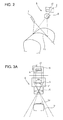
- the tire surface shape measuring device 1 uses an image capturing camera 6 to capture an image of a light cutting-plane line Ls formed by linear light emitted to the surfaces of rotating tires T (tire T 1 and tire T 2 ) and measures heights of various portions of each tire T by performing shape detection by a light cutting-plane method according to the captured image. In addition, the tire surface shape measuring device 1 replaces the measured heights of the various portions of the tire T with corresponding brightness values to obtain a two-dimensional image (inspection image) of the surfaces of the tire T.
- the tire surface shape measuring device 1 has a tire rotating machine 2, sensor units 3, an encoder 4, and an image processing device 5.
- Figs. 1A and 1B the same tire surface shape measuring device 1 is illustrated, but only tires T, which are measurement targets, differ.
- Fig. 1A illustrates a state in which a tire T 1 with a small size is being measured
- Fig. 1B illustrates a state in which a tire T 2 with a large size is being measured.
- the tire rotating machine 2 is a rotating device having a motor that rotates the tire T, which is a target the shape of which is to be detected, around its rotational axis and the like.
- the tire rotating machine rotates the tire T at a rotational speed of, for example, 60 rpm.
- the sensor units 3, described later detect (measure) the surface shape of the entire circumference of the tire T.
- Each sensor unit 3 which detects the surface shape of the tire T, is a unit that has a linear light emitting means 7 that emits linear light (light cutting-plane line) to the surface of the rotating tire T, an image capturing camera (image capturing means) 6 that captures an image of a light cutting-plane line reflected on the surface of the tire T, and the like.
- a sensor unit 3a used to detect the shape of the tread surface of the tire T and two sensor units 3b and 3c used to detect the shapes of two sidewall surfaces are included.
- the sensor unit 3a is disposed so as to face the tread surface, and the sensor units 3b and 3c are disposed so as to face the sidewall surfaces.
- the linear light emitting means 7 has a linear light source that emits sheet-like linear light.
- the linear light source is formed with, for example, an LED, a halogen lamp, or the like.
- the sheet-like linear light emitted from the linear light emitting means 7 forms a single light cutting-plane line Ls on the surface of the tire T.
- the image capturing camera 6 has a camera lens 8 and an image capturing element 9, which is an area image sensor formed with, for example, a CCD or CMOS.
- the image capturing element 9 has, for example, 1920 ⁇ 1080 pixels.
- the image capturing camera 6 obtains a captured image of the light cutting-plane line Ls by capturing an image v1 of the light cutting-plane line Ls projected on the image capturing surface of the image capturing element 9.
- the encoder 4 attached to the tire rotating machine 2 is a sensor that detects the rotational angle of the rotational axis of the tire rotating machine 2, that is, the rotational angle of the tire T and outputs the detected rotational angle as a detection signal.
- the detection signal is used to control the capturing timing of the image capturing camera 6 included in the sensor unit 3.
- the image processing device 5 receives a detection signal output from the encoder 4 each time the tire T, which rotates a rotational speed of, for example, 60 rpm, rotates through a prescribed angle, and controls the image capturing camera 6 included in the sensor unit 3 so that an image is captured according to the reception timing of the detection signal.
- images are captured at a prescribed image capturing rate (image capturing frequency) that matches the reception signals of detection signals.
- the image processing device 5 is a device that controls each sensor unit 3 and captures an image of the light cutting-plane line Ls.
- the image processing device 5 also fetches the captured image through a frame memory and obtains a distribution of tire surface heights from the light cutting-plane line Ls included in the fetched image.
- the image processing device 5 has an image capture area setting means 10 that sets an effective image capture area A, which is used to capture the image of the light cutting-plane line Ls, on the image capturing surface of the image capturing element 9 included in the image capturing camera 6, and also has a pixel data extracting means 11 that extracts only pixel data present in the set effective image capture area A from the image capturing element 9.
- the image processing device 5 has a shape detecting means 12 that extracts the light cutting-plane line Ls by, for example, applying binarization processing to the fetched image and obtains a distribution of tire surface heights from the obtained light cutting-plane line Ls according to the principle of the triangulation method.
- the image processing device 5 is formed with, for example, a personal computer having a frame memory or the like; the image capture area setting means 10 and pixel data extracting means 11 output commands to a control unit in the image capturing camera 6 incorporated into the sensor unit 3 for control purposes.
- the image capture area setting means 10 and pixel data extracting means 11 in the image processing device 5 will be described with reference to Figs. 3A to 5 .
- the image capture area setting means 10 sets the effective image capture area A on the image capturing surface so that images of linear light formed on the image capturing surface of the image capturing element 9, that is, all images v1 of light cutting-plane lines Ls projected on the image capturing surface are included.
- Fig. 3A schematically illustrates a correspondence between a light cutting-plane line Ls formed on a tread surface of a small tire T 1 and the image v1 of the light cutting-plane line Ls projected on the image capturing surface of the image capturing element 9.
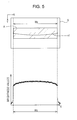
- Fig. 3B schematically illustrates a correspondence between a light cutting-plane line Ls formed on a tread surface of a large tire T 2 and the image v1 on the image capturing surface.
- FIGs. 3A and 3B the shooting distances (working distances) from the camera lens 8 to the tread surface of the tire T are almost the same.
- these drawings indicate that when the size of the tire T differs, the length of the light cutting-plane line Ls differs and thereby the length of the image v1 on the image capturing surface also differs.
- the light cutting-plane line Ls is short and the image v1 on the image capturing surface is also short (the width is W 1 ).
- the light cutting-plane line Ls is long and the image v1 on the image capturing surface is also long (the width is W 2 ).
- the image capture area setting means 10 sets the effective image capture area A that matches the length of the image v1 on the image capturing surface so as to include all images v1, the lengths of which vary with the tire T.
- the effective image capture area A is a set of pixels on the image capturing surface that are actually used to capture the image v1 of the light cutting-plane line Ls; the effective image capture area A is set so as to be a rectangle when the image capturing surface of the image capturing element 9 is viewed from the front. As illustrated in Figs.
- the ranges of the X coordinates and Y coordinates of pixels on the image capturing surface are determined, and a set of pixels having X coordinates and Y coordinates (pixel addresses) within these ranges are taken as the effective image capture area A, a rectangular effective image capture area A with its long side being along the longitudinal direction of the image v1 can be set.
- the upper limit and lower limit of this X coordinate range may be the X coordinates at both ends of the image v1 of the light cutting-plane line Ls.
- the upper limit of the Y coordinate range may determined so that it is adequately larger than the maximum value of the Y coordinates of the image v1
- lower limit of the Y coordinate range may be determined so that it is adequately smaller than the minimum value of the Y coordinates of the image v1.
- the effective image capture area A can be set according to the length of the image v1 and the image v1 can be reliably captured within the effective image capture area A.
- the pixel data extracting means 11 retrieves, from the image capturing element 9, pixel data (brightness data of pixels) present in the effective image capture area A set by the image capture area setting means 10.
- the pixel data extracting means 11 issues, to the control unit in the image capturing camera 6, a command to transfer horizontally scanned data for one pixel every three pixels, for example, along the Y axis from the pixel data in the effective image capture area A.
- the pixel data extracting means 11 issues, to the outside, a command to transfer pixel data for one pixel every two pixels, for example, along X axis in relation to the transferred horizontally scanned data. That is, the pixel data extracting means 11 sets 100 horizontal scanning lines and 600 vertical scanning lines for the effective image capture area A as a predetermined number of scanning lines, and extracts pixel data from the effective image capture area A as measurement signals.
- the pixel data extracting means 11 issues, to the control unit in the image capturing camera 6, a command to transfer horizontally scanned data for one pixel every four pixels, for example, along the Y axis from the pixel data in the effective image capture area A.
- the pixel data extracting means 11 issues, to the outside, a command to transfer pixel data for one pixel every three pixels, for example, along X axis in relation to the transferred horizontally scanned data.
- the pixel data extracting means 11 sets 100 horizontal scanning lines and 600 vertical scanning lines for the effective image capture area A, and extracts pixel data.
- the pixel data extracting means 11 issues, to the control unit in the image capturing camera 6, a command to transfer horizontally scanned data for one pixel every [P y /n] pixels along the Y axis from the pixel data in the effective image capture area A.
- the pixel data extracting means 11 also issues, to the outside, a command to transfer pixel data for one pixel every [P x /m] pixels along X axis in relation to the transferred horizontally scanned data.
- [P y /n] and [P x /m] are integers obtained by rounding off or cutting down P y /n and P x /m.
- a brightness value distribution over the width W 2 of the light cutting-plane line Ls, as illustrated in the lower portion in Fig. 5 is obtained from the pixel data extracted in this way.
- the number of horizontal scanning lines (100 in the above example) and the number of vertical scanning lines (600 in the above example) are not changed but are fixed. That is, the number of scanning lines remains the same regardless of whether the tread surface of the small tire T 1 or the tread surface of the large tire T 2 is measured. Accordingly, even if tires with different sidewall surface thicknesses or different tread surface widths are attached to the tire surface shape measuring device 1, surface shapes can be detected with the same image resolution and high precision, which are achieved by a fixed number of scanning lines.
- the number of scanning lines (lines to be extracted) is determined within a range in which the image capturing frequency of the image capturing element 9 can achieved.
- the shape detecting means 12 in the image processing device 5 applies the principle of the triangulation method to the image of the light cutting-plane line Ls, which is formed from the pixel data (brightness data) extracted by the pixel data extracting means 11, to obtain height distribution information about a portion (corresponding to one line on the tire surface) to which the light cutting-plane line Ls was emitted.
- the tire surface shape measuring device 1 in this embodiment, having the structure described above can set the effective image capture area A having an appropriate size through the image capture area setting means 10, and can set pixel data of a captured image from the effective image capture area A through the pixel data extracting means 11.
- the tire surface shape measuring device 1 has the sensor unit 3a used to detect the shape of the tread surface of the tire T 1 and the two sensor units 3b and 3c used to detect the shapes of its two sidewall surfaces.
- the sensor unit 3a is disposed so as to face the tread surface, and the sensor units 3b and 3c are disposed so as to face the sidewall surfaces.
- Each of the sensor units 3a, 3b, and 3c has the linear light emitting means 7, which emits linear light to the surface of the tire T 1 , and the image capturing means 6, which captures an image of a light cutting-plane line Ls reflected on the surface of the tire T 1 .
- Three linear light rays from the sensor units 3a, 3b, and 3c may be mutually linked and may be a single linear light ray that is continuous on the surface of the tire T 1 .
- these linear light rays may be discontinuous linear light rays.
- the image captured by the image capturing camera 6 disposed in each of the sensor units 3a, 3b, and 3c is sent to the image processing device 5.
- the sensor units 3a, 3b, and 3c may be operated at the same time or may be operated at different times. Either operation mode may be selected depending on the image capturing situation of the light cutting-plane line Ls, as described later.
- the linear light emitting means 7 in the sensor unit 3a first emits linear light to the tread surface of the tire T 1 .
- the emitted linear light forms a light cutting-plane line Ls on the tread surface of the tire T 1 .
- the image capturing camera 6 captures an image of the formed light cutting-plane line Ls, and forms the image v1 of the light cutting-plane line Ls on the image capturing surface of the image capturing element 9.
- the periphery of the light cutting-plane line Ls is dark, so almost nothing other than the image v1 of the light cutting-plane line Ls is captured. Accordingly, it can be thought that only the image v1 is captured by the image capturing camera 6 and the captured image v1 directly reflects the shape and width of the tread surface by itself.
- the image capture area setting means 10 in the image processing device 5 sets the rectangular effective image capture area A on the image capturing surface of the image capturing element 9 (image capture area setting step) so that the distance (width) W 1 between the X coordinates at both ends of the image v1 becomes the length of the long side in the longitudinal direction.
- the image processing device 5 After having set the effective image capture area A, the image processing device 5 captures an image of the light cutting-plane line Ls over the entire circumference of the tire T 1 by using only the effective image capture area A on the image capturing surface of the image capturing element 9 in the sensor unit 3a.
- the image processing device 5 receives a detection signal output from the encoder 4.
- the image processing device 5 captures an image of the light cutting-plane line Ls by using the image capturing camera 6 of the sensor unit 3a according to the reception timing of the detection signal.
- the image capturing camera 6 captures images of a plurality of light cutting-plane lines Ls formed at prescribed positions on the tread surface over the entire circumference of the tire T 1 at a prescribed image capturing frequency (2 kHz, for example) matching the reception timing of the detection signal, so a plurality of images v1 of light cutting-plane lines Ls formed on the image capturing surface of the image capturing element 9 are obtained.
- the pixel data extracting means 11 extracts pixel data (a predetermined number of measurement signals) corresponding to a prescribed number of scanning lines (600 lines ⁇ 100 lines, for example) from the image of the light cutting-plane line Ls, which has been captured in the effective image capture area A, and transfers the extracted pixel data to the frame memory (pixel data extraction step).
- the image processing device 5 Upon completion of image capturing on the tread surface, the image processing device 5 operates the sensor unit 3b to capture an image of the upper sidewall of the tire T 1 by the same method as when the sensor unit 3a captures an image of the tread surface. Images of a plurality of light cutting-plane lines Ls formed at prescribed positions on the upper sidewall surface are captured over the entire circumference of the tire T 1 by the image capturing by the sensor unit 3b, obtaining a plurality of images v1 of light cutting-plane lines Ls formed on the image capturing surface of the image capturing element 9.
- the image processing device 5 Upon completion of image capturing on the upper sidewall, the image processing device 5 operates the sensor unit 3c to capture an image of the lower sidewall of the tire T 1 by the same method. Images of a plurality of light cutting-plane lines Ls formed at prescribed positions on the lower sidewall surface are captured over the entire circumference of the tire T 1 by the image capturing by the sensor unit 3c, obtaining a plurality of image v1 of light cutting-plane lines Ls formed on the image capturing surface of the image capturing element 9.
- the shape detecting means 12 applies the principle of the triangulation method to the images v1 of the plurality of light cutting-plane lines Ls, which are formed from the pixel data (brightness data) extracted by the pixel data extracting means 11 and then transferred to the frame memory, for each of the tread surface and both sidewalls of the tire T 1 .
- Height distribution information about a portion (corresponding to one line on the tire surface) to which each light cutting-plane line Ls was emitted is obtained by applying the triangulation method to the image v1.
- the shape detecting means 12 links the height distribution information obtained from all images v1 for the entire circumference of the tire T 1 to obtain a two-dimensional image (inspection image) of the tread surface, upper sidewall surface, and lower sidewall surface of the tire T 1 .
- one light cutting-plane line Ls is formed on each of the tread surface, upper sidewall surface, and lower sidewall surface. If the positions of the light cutting-plane lines Ls formed on these tire surfaces are the same in the whole circumference direction of the tire T 1 , there is a possibility that an image of an end of a light cutting-plane line Ls formed on an adjacent tire surface is captured on the image capturing surface illustrated in Figs. 4 and 5 . If an image of an end of an adjacent light cutting-plane line Ls is captured, an image of the tire T 1 is captured by making a switchover among the sensor units 3a to 3c as described above.
- the sensor units 3a to 3c can be concurrently operated.
- These light cutting-plane lines Ls do not need to be formed at the same position in the whole circumference direction of the tire T 1 ; they may be formed at different positions in the whole circumference direction of the tire T 1 .
- the method of measuring the tire T 2 is the same as the method of measuring the tire T 1 .
- the image processing device 5 sequentially switches the sensor units 3a to 3c and captures the images v1 of light cutting-plane lines Ls formed on the tread surface, upper sidewall surface, and lower sidewall surface of the tire T 2 .
- the image capture area setting means 10 sets the effective image capture area A with the width W 2 , which is shorter than the width W 1 , according to the image v1, and the pixel data extracting means 11 extracts pixel data (a predetermined number of measurement signals) corresponding to a prescribed number of scanning lines (600 lines ⁇ 100 lines, for example) from the image of the light cutting-plane line Ls, which has been captured in the effective image capture area A, and transfers the extracted pixel data to the frame memory.
- a two-dimensional image (inspection image) of the tread surface, upper sidewall surface, and lower sidewall surface of the tire T 2 is obtained by the same method as the measuring method for the tire T 1 .
- the image v1 of the light cutting-plane line Ls can be captured by setting the effective image capture area A according to the length of the image v1 on the image capturing surface.
- the effective image capture area A had been first set on the image capturing surface of the image capturing element 9, after which pixel data extracted from the image of the light cutting-plane line Ls, the image being captured in the effective image capture area A, has been transferred to the frame memory.
- this is not a limitation; all images captured in the image capturing element 9 may be transferred to the frame memory before the effective image capture area A is set. Then, it is also possible to set the effective image capture area A for the captured images stored in the frame memory and then extract the pixel data.
Landscapes
- Physics & Mathematics (AREA)
- General Physics & Mathematics (AREA)
- Engineering & Computer Science (AREA)
- Computer Vision & Pattern Recognition (AREA)
- Multimedia (AREA)
- Signal Processing (AREA)
- Mechanical Engineering (AREA)
- Length Measuring Devices By Optical Means (AREA)
- Tires In General (AREA)
Applications Claiming Priority (2)
| Application Number | Priority Date | Filing Date | Title |
|---|---|---|---|
| JP2011094056A JP2012225795A (ja) | 2011-04-20 | 2011-04-20 | タイヤ表面形状測定装置及びタイヤ表面形状測定方法 |
| PCT/JP2012/060098 WO2012144430A1 (fr) | 2011-04-20 | 2012-04-13 | Dispositif de mesure de la forme de la surface d'un pneu et procédé de mesure de la forme de la surface d'un pneu |
Publications (2)
| Publication Number | Publication Date |
|---|---|
| EP2700903A1 true EP2700903A1 (fr) | 2014-02-26 |
| EP2700903A4 EP2700903A4 (fr) | 2014-10-22 |
Family
ID=47041538
Family Applications (1)
| Application Number | Title | Priority Date | Filing Date |
|---|---|---|---|
| EP12774229.4A Withdrawn EP2700903A4 (fr) | 2011-04-20 | 2012-04-13 | Dispositif de mesure de la forme de la surface d'un pneu et procédé de mesure de la forme de la surface d'un pneu |
Country Status (7)
| Country | Link |
|---|---|
| US (1) | US20140043472A1 (fr) |
| EP (1) | EP2700903A4 (fr) |
| JP (1) | JP2012225795A (fr) |
| KR (1) | KR20130137682A (fr) |
| CN (1) | CN103477183A (fr) |
| TW (1) | TW201250201A (fr) |
| WO (1) | WO2012144430A1 (fr) |
Families Citing this family (19)
| Publication number | Priority date | Publication date | Assignee | Title |
|---|---|---|---|---|
| US9805697B1 (en) | 2012-06-01 | 2017-10-31 | Hunter Engineering Company | Method for tire tread depth modeling and image annotation |
| JP6155038B2 (ja) * | 2013-02-08 | 2017-06-28 | リコーエレメックス株式会社 | 外観検査装置および外観検査方法 |
| US10063837B2 (en) * | 2013-07-25 | 2018-08-28 | TIREAUDIT.COM, Inc. | System and method for analysis of surface features |
| DE102014205515A1 (de) * | 2014-03-25 | 2015-10-01 | Robert Bosch Gmbh | Verfahren und Vorrichtung zum Überprüfen der Reifenmontage an einem Fahrzeug |
| JP6265864B2 (ja) * | 2014-08-12 | 2018-01-24 | 株式会社神戸製鋼所 | タイヤ試験装置 |
| CN107076549B (zh) | 2015-05-29 | 2019-05-10 | 新日铁住金株式会社 | 金属体的形状检查装置和金属体的形状检查方法 |
| EP3182060B1 (fr) | 2015-06-05 | 2023-07-26 | Nippon Steel Corporation | Appareil d'inspection de forme pour un corps métallique et procédé d'inspection de forme pour un corps métallique |
| JP6457894B2 (ja) * | 2015-06-24 | 2019-01-23 | 住友ゴム工業株式会社 | トレッド形状測定方法及びトレッド形状測定装置 |
| US11472234B2 (en) | 2016-03-04 | 2022-10-18 | TIREAUDIT.COM, Inc. | Mesh registration system and method for diagnosing tread wear |
| US10789773B2 (en) | 2016-03-04 | 2020-09-29 | TIREAUDIT.COM, Inc. | Mesh registration system and method for diagnosing tread wear |
| KR101867175B1 (ko) * | 2016-09-26 | 2018-06-12 | 금호타이어 주식회사 | 타이어 반제품의 결함 감지 방법 및 장치 |
| US11453259B2 (en) | 2018-02-01 | 2022-09-27 | Pixart Imaging Inc. | Object surface managing method and object surface managing system |
| CN109269566B (zh) * | 2018-10-22 | 2024-05-10 | 上海易清智觉自动化科技有限公司 | 轮胎检测系统 |
| CN110398214B (zh) * | 2019-08-01 | 2021-05-11 | 桂林梵玛科机械有限公司 | 轮胎胎体外轮廓尺寸快速测量方法 |
| CN110942444B (zh) * | 2019-09-30 | 2023-05-02 | 阿里巴巴集团控股有限公司 | 物体检测方法和装置 |
| CN111536903B (zh) * | 2020-04-29 | 2024-07-02 | 浙江大学 | 一种多个线激光传感器拼接测量轮胎形貌的装置及方法 |
| JP2023069113A (ja) * | 2021-11-05 | 2023-05-18 | 住友ゴム工業株式会社 | タイヤプロファイルの測定装置及び測定方法 |
| JP2024040819A (ja) * | 2022-09-13 | 2024-03-26 | 第一実業ビスウィル株式会社 | 環状製品の外観検査装置 |
| WO2024219298A1 (fr) * | 2023-04-17 | 2024-10-24 | 株式会社村田製作所 | Dispositif d'observation de pneu et procédé d'observation de pneu |
Family Cites Families (10)
| Publication number | Priority date | Publication date | Assignee | Title |
|---|---|---|---|---|
| JP3548465B2 (ja) * | 1999-09-08 | 2004-07-28 | キヤノン株式会社 | 撮像装置及び撮像方法 |
| JP2001280917A (ja) * | 2000-03-31 | 2001-10-10 | Minolta Co Ltd | 3次元計測装置 |
| JP3759584B2 (ja) * | 2001-11-30 | 2006-03-29 | 澁谷工業株式会社 | 物体の三次元高さ計測方法 |
| JP2003240521A (ja) | 2002-02-21 | 2003-08-27 | Bridgestone Corp | 被検体の外観・形状検査方法とその装置、及び、被検体の外観・形状検出装置 |
| JP2005286241A (ja) * | 2004-03-30 | 2005-10-13 | Fuji Mach Mfg Co Ltd | 電子回路製造関連作業機 |
| US7269997B2 (en) * | 2004-06-03 | 2007-09-18 | Snap-On Incorporated | Non-contact method and system for tire analysis |
| EP2172737B1 (fr) * | 2007-08-06 | 2013-04-24 | Kabushiki Kaisha Kobe Seiko Sho | Système de mesure de forme de pneu |
| JP5089286B2 (ja) * | 2007-08-06 | 2012-12-05 | 株式会社神戸製鋼所 | 形状測定装置,形状測定方法 |
| JP5245817B2 (ja) * | 2008-12-27 | 2013-07-24 | Jfeスチール株式会社 | 鋼板の形状計測方法及び形状計測装置 |
| JP5191055B2 (ja) * | 2009-02-20 | 2013-04-24 | パルステック工業株式会社 | 3次元形状測定装置および3次元形状測定方法 |
-
2011
- 2011-04-20 JP JP2011094056A patent/JP2012225795A/ja active Pending
-
2012
- 2012-04-13 WO PCT/JP2012/060098 patent/WO2012144430A1/fr not_active Ceased
- 2012-04-13 KR KR1020137027299A patent/KR20130137682A/ko not_active Ceased
- 2012-04-13 US US14/110,425 patent/US20140043472A1/en not_active Abandoned
- 2012-04-13 CN CN2012800190787A patent/CN103477183A/zh active Pending
- 2012-04-13 EP EP12774229.4A patent/EP2700903A4/fr not_active Withdrawn
- 2012-04-19 TW TW101113949A patent/TW201250201A/zh unknown
Also Published As
| Publication number | Publication date |
|---|---|
| US20140043472A1 (en) | 2014-02-13 |
| CN103477183A (zh) | 2013-12-25 |
| EP2700903A4 (fr) | 2014-10-22 |
| TW201250201A (en) | 2012-12-16 |
| JP2012225795A (ja) | 2012-11-15 |
| WO2012144430A1 (fr) | 2012-10-26 |
| KR20130137682A (ko) | 2013-12-17 |
Similar Documents
| Publication | Publication Date | Title |
|---|---|---|
| EP2700903A1 (fr) | Dispositif de mesure de la forme de la surface d'un pneu et procédé de mesure de la forme de la surface d'un pneu | |
| US7755772B2 (en) | Tire shape measuring system | |
| US10151580B2 (en) | Methods of inspecting a 3D object using 2D image processing | |
| EP3163252A1 (fr) | Dispositif de mesure de forme tridimensionnelle, systeme, programme de mesure de forme tridimensionnelle, support d'informations lisible par ordinateur et procede de mesure de forme tridimensionnelle | |
| US20130114861A1 (en) | Device and method for recognizing three-dimensional position and orientation of article | |
| US20120242824A1 (en) | Device and method for inspecting tyre shape | |
| US12566060B2 (en) | Three-dimensional measurement device | |
| JP5222430B1 (ja) | 寸法計測装置、寸法計測方法及び寸法計測装置用のプログラム | |
| KR101342523B1 (ko) | 위치 측정 장치 및 위치 측정 방법 | |
| JP2012215394A (ja) | 三次元計測装置および三次元計測方法 | |
| CN104515477B (zh) | 三维测定装置、三维测定方法以及基板的制造方法 | |
| JP2010190886A (ja) | パンタグラフ高さ測定装置及びそのキャリブレーション方法 | |
| JP6904624B1 (ja) | クラブヘッド計測用マークおよび画像処理装置 | |
| EP3070431B1 (fr) | Appareil d'inspection visuelle et procédé d'inspection visuelle | |
| EP2960621B1 (fr) | Dispositif d'inspection de forme | |
| JP2013134176A (ja) | 撮像装置および撮像方法 | |
| JP5342977B2 (ja) | 画像処理方法 | |
| CN114264243B (zh) | 一种检测压接焊点以及测量压接焊点之间线弧高度的方法 | |
| CN209624417U (zh) | 基于线共焦相机的触摸屏缺陷检测装置 | |
| KR101863839B1 (ko) | 영상을 이용한 고속, 반복 길이 측정방법 및 장치 | |
| JP2009250777A (ja) | 表面検査装置および表面検査方法 | |
| JP2001033397A (ja) | 物体表面の欠陥検出方法及び欠陥検出装置 | |
| JP5956241B2 (ja) | 検査方法及び検査装置 | |
| JP2011095071A (ja) | 非接触計測装置および非接触計測方法 | |
| JP2000097678A (ja) | 表面形状計測装置およびその方法 |
Legal Events
| Date | Code | Title | Description |
|---|---|---|---|
| PUAI | Public reference made under article 153(3) epc to a published international application that has entered the european phase |
Free format text: ORIGINAL CODE: 0009012 |
|
| 17P | Request for examination filed |
Effective date: 20130826 |
|
| AK | Designated contracting states |
Kind code of ref document: A1 Designated state(s): AL AT BE BG CH CY CZ DE DK EE ES FI FR GB GR HR HU IE IS IT LI LT LU LV MC MK MT NL NO PL PT RO RS SE SI SK SM TR |
|
| DAX | Request for extension of the european patent (deleted) | ||
| A4 | Supplementary search report drawn up and despatched |
Effective date: 20140919 |
|
| RIC1 | Information provided on ipc code assigned before grant |
Ipc: G01B 11/24 20060101AFI20140915BHEP Ipc: B60C 19/00 20060101ALI20140915BHEP |
|
| STAA | Information on the status of an ep patent application or granted ep patent |
Free format text: STATUS: THE APPLICATION IS DEEMED TO BE WITHDRAWN |
|
| 18D | Application deemed to be withdrawn |
Effective date: 20150421 |