EP2700909B1 - Drehmelderschnittstelle - Google Patents
Drehmelderschnittstelle Download PDFInfo
- Publication number
- EP2700909B1 EP2700909B1 EP13179620.3A EP13179620A EP2700909B1 EP 2700909 B1 EP2700909 B1 EP 2700909B1 EP 13179620 A EP13179620 A EP 13179620A EP 2700909 B1 EP2700909 B1 EP 2700909B1
- Authority
- EP
- European Patent Office
- Prior art keywords
- secondary signal
- signal
- excitation
- peak
- sign
- Prior art date
- Legal status (The legal status is an assumption and is not a legal conclusion. Google has not performed a legal analysis and makes no representation as to the accuracy of the status listed.)
- Active
Links
Images

Classifications
-
- G—PHYSICS
- G01—MEASURING; TESTING
- G01D—MEASURING NOT SPECIALLY ADAPTED FOR A SPECIFIC VARIABLE; ARRANGEMENTS FOR MEASURING TWO OR MORE VARIABLES NOT COVERED IN A SINGLE OTHER SUBCLASS; TARIFF METERING APPARATUS; MEASURING OR TESTING NOT OTHERWISE PROVIDED FOR
- G01D5/00—Mechanical means for transferring the output of a sensing member; Means for converting the output of a sensing member to another variable where the form or nature of the sensing member does not constrain the means for converting; Transducers not specially adapted for a specific variable
- G01D5/12—Mechanical means for transferring the output of a sensing member; Means for converting the output of a sensing member to another variable where the form or nature of the sensing member does not constrain the means for converting; Transducers not specially adapted for a specific variable using electric or magnetic means
- G01D5/14—Mechanical means for transferring the output of a sensing member; Means for converting the output of a sensing member to another variable where the form or nature of the sensing member does not constrain the means for converting; Transducers not specially adapted for a specific variable using electric or magnetic means influencing the magnitude of a current or voltage
- G01D5/20—Mechanical means for transferring the output of a sensing member; Means for converting the output of a sensing member to another variable where the form or nature of the sensing member does not constrain the means for converting; Transducers not specially adapted for a specific variable using electric or magnetic means influencing the magnitude of a current or voltage by varying inductance, e.g. by a movable armature
- G01D5/204—Mechanical means for transferring the output of a sensing member; Means for converting the output of a sensing member to another variable where the form or nature of the sensing member does not constrain the means for converting; Transducers not specially adapted for a specific variable using electric or magnetic means influencing the magnitude of a current or voltage by varying inductance, e.g. by a movable armature by influencing the mutual induction between two or more coils
- G01D5/2073—Mechanical means for transferring the output of a sensing member; Means for converting the output of a sensing member to another variable where the form or nature of the sensing member does not constrain the means for converting; Transducers not specially adapted for a specific variable using electric or magnetic means influencing the magnitude of a current or voltage by varying inductance, e.g. by a movable armature by influencing the mutual induction between two or more coils by movement of a single coil with respect to two or more coils
-
- G—PHYSICS
- G01—MEASURING; TESTING
- G01D—MEASURING NOT SPECIALLY ADAPTED FOR A SPECIFIC VARIABLE; ARRANGEMENTS FOR MEASURING TWO OR MORE VARIABLES NOT COVERED IN A SINGLE OTHER SUBCLASS; TARIFF METERING APPARATUS; MEASURING OR TESTING NOT OTHERWISE PROVIDED FOR
- G01D5/00—Mechanical means for transferring the output of a sensing member; Means for converting the output of a sensing member to another variable where the form or nature of the sensing member does not constrain the means for converting; Transducers not specially adapted for a specific variable
- G01D5/12—Mechanical means for transferring the output of a sensing member; Means for converting the output of a sensing member to another variable where the form or nature of the sensing member does not constrain the means for converting; Transducers not specially adapted for a specific variable using electric or magnetic means
- G01D5/14—Mechanical means for transferring the output of a sensing member; Means for converting the output of a sensing member to another variable where the form or nature of the sensing member does not constrain the means for converting; Transducers not specially adapted for a specific variable using electric or magnetic means influencing the magnitude of a current or voltage
- G01D5/20—Mechanical means for transferring the output of a sensing member; Means for converting the output of a sensing member to another variable where the form or nature of the sensing member does not constrain the means for converting; Transducers not specially adapted for a specific variable using electric or magnetic means influencing the magnitude of a current or voltage by varying inductance, e.g. by a movable armature
- G01D5/22—Mechanical means for transferring the output of a sensing member; Means for converting the output of a sensing member to another variable where the form or nature of the sensing member does not constrain the means for converting; Transducers not specially adapted for a specific variable using electric or magnetic means influencing the magnitude of a current or voltage by varying inductance, e.g. by a movable armature differentially influencing two coils
- G01D5/2291—Linear or rotary variable differential transformers (LVDTs/RVDTs) having a single primary coil and two secondary coils
Definitions
- the present invention is related to resolvers, and in particular to resolvers employing multiplexed signal sampling.
- Resolvers are used in a variety of applications to provide position feedback.
- resolvers are oftentimes associated with actuators to provide feedback regarding the state of the actuator (e.g., open, partially open, closed).
- a typical resolver includes an excitation coil and first and second secondary coils positioned 90° out of phase with one another.
- An excitation signal supplied to the excitation coil generates corresponding output signals in the first and second secondary coils.
- the orientation or position of the excitation coil can be determined.
- a resolver monitors the excitation signal and the corresponding output signals simultaneously to determine position.
- a multiplexer is used to sample the respective signals successively as opposed to simultaneously.
- the resolver position is only determinable within a 90° range. If the resolver position rotates more than 90°, the position cannot be determined without knowledge of the quadrant in which the position is located. For example, a first quadrant may represent angles from 0-90°, the second quadrant represents angles from 90-180°, the third quadrant represents angles from 180-270°, and the third quadrant represents angles from 270-360°. In these applications, the magnitude alone is insufficient to determine position.
- EP 2177879 and US 2002/173931 are concerned with processing resolver signals.
- the invention comprises a resolver as defined in claim 1 and a method of calculating resolver position as defined in claim 6.
- Fig. 1 is a block diagram of resolver interface 10 according to an embodiment of the present invention.
- Resolver interface 10 includes square wave generator 12, excitation counter 14, filter 16, excitation coil 18, secondary coils 20a, 20b, and sample circuit 21, which includes multiplexer 22, input filter 24, and analog-digital converter 26.
- Controller 28 determines a position of the resolver (i.e., of excitation coil 18) based on the magnitude and sign of the monitored signals as provided by A/D converter 26.
- Square wave generator 12 generates a square wave signal having a defined frequency based on the count provided by excitation counter 14.
- Filter 16 shapes the square wave signal into a sine wave excitation signal having a frequency equal to that defined by excitation counter 14.
- the sine wave excitation signal is supplied to excitation coil 18, and monitored by multiplexer 22.
- the excitation signal provided to excitation coil 18 results in the generation of secondary signals (labeled "COSINE” and “SINE” because of the 90° phase shift between them) in secondary coils 20a and 20b, respectively.
- the position of exciter coil 18 is expressed as an angle ⁇ relative to secondary coil 20a.
- the magnitude of the secondary signals COSINE and SINE generated in secondary coils 20a and 20b, respectively, depend on the angle ⁇ .
- determining the position of excitation coil 18 depends on the phase or "sign" of the secondary signals in relation to the excitation signal.
- Multiplexer 22 samples the excitation signal and the secondary signals COSINE and SINE generated in secondary coils 20a and 20b, and provides a multiplexed output to filter 24.
- the filtered output is provided to A/D converter 26, which converts the analog samples to digital signals that indicate the magnitude and sign of the monitored excitation signal and secondary signals COSINE and SINE. Based on these inputs, controller 28 determines the position 0 of excitation coil 18.
- controller 28 samples the excitation counter used to generate the square wave signal and determines the excitation phase delay between the start of the square wave signal (e.g., counter equal to zero) and the peak of the monitored excitation signal. Based on that information, controller 28 can determine the corresponding peak of both the monitored SINE and COSINE signals.
- controller 28 compares the peak with samples 180° out of phase with the peak. If the sampled peak is greater than the out of phase samples, then the sign or phase of the monitored signal is positive. If the sampled peak is less than the out of phase samples, then the sign or phase of the monitored signal is negative. Based on the determined sign of the SINE and COSINE signal, the position quadrant (e.g., 0-90°, 90-180°, 180-270°, 270-360°) can be determined. Then, based on the determined quadrant and magnitude of the monitored signals, controller 28 determines the position ⁇ of the resolver.
- the position quadrant e.g., 0-90°, 90-180°, 180-270°, 270-360°
- a benefit of the present invention is all signals are provided through the same sampling circuit hardware (e.g., multiplexer 22, input filter 24, and analog-digital converter 26). In this way, a bias that may otherwise be introduced by sampling all three signals simultaneously via different hardware elements is remedied by applying all sampled signals through the same hardware configuration.
- sampling circuit hardware e.g., multiplexer 22, input filter 24, and analog-digital converter 26.
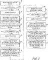
- Fig. 2 is a flowchart illustrating quadrant calculation performed by controller 28 according to an embodiment of the present invention.
- Fig. 2 is discussed with reference to Figs. 3 and 4 , which illustrate graphically the sampling of the excitation signal and secondary signals, respectively, along with illustrating calculations performed by controller 28.
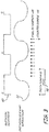
- Steps 30 through 36 are described with reference to Fig. 3 , which illustrates square wave signal 60, excitation signal 62, and analog samples 64 of the excitation signal.
- square wave signal 60 is generated by square wave generator 14 (shown in Fig. 1 ), and converted to a sine wave signal 62 by filter 16 (also shown in Fig. 1 ).
- excitation sine wave signal 62 is sampled by sample circuit 21, which includes multiplexer 22, input filter 24 and A/D converter 26 (as shown in Fig. 1 ).
- the excitation signal is monitored for an entire period although other sampling periods may be utilized. Based on the sampling rate and fundamental frequency of the excitation square wave, the number of samples per period is known. In the embodiment shown in Fig. 3 , twelve samples are taken by period of the excitation signal.
- controller 28 determines whether the last sample of the period has been recorded. If not, then sampling continues at step 30. If the last sample has been sampled, then at step 34 the excitation counter 14 is sampled.
- the counter sample represents the count the square wave generator uses to generate the excitation square wave, and can be used to determine the start of the square wave signal.
- controller 28 calculates an excitation phase delay value 68 based on the sampled counter and the peak of the sampled excitation signal.
- the excitation phase delay value 68 is the difference between the beginning of the excitation square wave signal 60 and the peak of the sampled excitation signal 62.
- the beginning of the excitation square wave signal 60 is determined based on the sampled counter value.
- the peak of the sampled excitation signal 62 is determined based on a comparison of the sampled analog signals to find the largest value.
- the excitation phase delay value 68 represents the time delay between the start of the square wave signal 60 and the peak of the excitation signal 62.
- the excitation phase delay value 68 is subsequently employed by controller 28 to find the corresponding peak value (although it may be in phase or out of phase) of the secondary signals SINE and COSINE, shown in Fig. 4 .
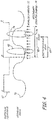
- Steps 38 through 46 are described with reference to Fig. 4 , which illustrates for the sake of reference square wave signal 60, SINE signal 70, analog samples 72 of SINE signal 70, and secondary counter sample 74.
- SINE signal 70 illustrates for the sake of reference square wave signal 60
- SINE signal 70 illustrates for the sake of reference square wave signal 60
- SINE signal 70 illustrates for the sake of reference square wave signal 60
- analog samples 72 of SINE signal 70 and secondary counter sample 74.
- the same operations discussed with respect to the SINE signal shown in Fig. 4 would be performed with respect to the COSINE signal to determine the sign of that signal.
- controller 28 monitors the SINE signal 70 corresponding with second secondary coil 20b. Once again, a full period of the SINE signal 70 is monitored.
- controller 28 determines whether the last sample has been received yet. If not, sampling continues at step 38. When the last sample has been taken, then at step 42 the excitation counter 14 is sampled.
- the expected peak 76 of sampled SINE signal 70 is located.
- the sampled counter value is utilized to count back to the beginning or start of the excitation square wave signal as indicated by line 78 in Fig. 4 .
- the excitation phase delay value 68 previously calculated to represent the distance between the start of the square wave signal and the peak of the monitored excitation signal, is likewise added to the start of the excitation square wave signal to locate the likely peak of the sampled SINE signal 70.
- other methods may be utilized to locate the portion of the sampled SINE signal that corresponds with the detected peak of the sampled excitation signal. However, because the sampled SINE signal may be either in phase or 180 degrees out of phase with the sampled excitation signal, locating the peak is not a matter of simply locating the largest value within the sampled waveform.
- the sampled peak 76 of the SINE signal is compared with samples 180° out of phase with sampled peak 76.
- samples 180° out of phase requires moving forward or backward six samples. If the sampled peak 76 is greater than the out-of-phase sample 82, this indicates that SINE signal 70 is in-phase with excitation signal 62 (i.e., positive sign). If the sampled peak 76 is less than the out-of-phase samples 82, this indicates that secondary signal 70 is out-of-phase with excitation signal 62 (i.e., negative sign).
- the sampled peak 76 is less than the out-of-phase samples 82, this indicates that secondary signal 70 is out-of-phase with excitation signal 62 (i.e., negative sign).
- Fig. 3 because twelve samples are taken each period, selecting samples 180° out of phase requires moving forward or backward six samples. If the sampled peak 76 is greater than the out-of-phase sample 82, this indicates that SINE signal 70 is in-phase with excitation signal 62 (
- a pair of samples (at times 0 and +1) located near the peak are averaged together, along with the samples located 180° from the peak (at times +6 and +7), and the averages are compared to one another. As the magnitudes of the monitored signals decrease, averaging the signals provides more accurate results.
- the process continues with respect to the other secondary signal (e.g., COSINE signal provided by secondary coil 20a), by monitoring the COSINE signal.
- the COSINE signal may be monitored first, and the SINE signal subsequent to the COSINE signal.
- controller 28 determines whether the last sample has been received, and continues sampling if it has not been received.
- the counter is sampled.
- the peak of the COSINE signal is located based on the calculated excitation phase delay and the counter sample.
- the sign of the COSINE signal is determined by comparing samples associated with the located peak with samples 180° out of phase with the detected peak.
- the position of excitation coil 18 (i.e., of the resolver) can be divided into four quadrants, as illustrated in the table below.
- the quadrant can be determined based on the sign of the monitored SINE and COSINE signals.
- the resolver angle 0 can be calculated according to the equations on the right.
- Quadrant SINE signal COSINE signal Resolver Angle ⁇ First Quadrant + + Second Quadrant + - Third Quadrant - - Fourth Quadrant - +
- the present invention provides the ability to determine position of a resolver that is capable of positions greater than 90 degrees.
- the present invention is applicable to embodiments in which the excitation signal, and both the first and secondary signals are not sampled simultaneously, but rather are provided through a multiplexer that samples the signals one at a time.
Landscapes
- Physics & Mathematics (AREA)
- General Physics & Mathematics (AREA)
- Engineering & Computer Science (AREA)
- Power Engineering (AREA)
- Transmission And Conversion Of Sensor Element Output (AREA)
Claims (13)
- Drehmelder, der Folgendes umfasst:eine Erregerspule (18), die ein Erregersignal empfängt;eine erste Sekundärspule (20a), die ein erstes Sekundärsignal als Antwort auf das Erregersignal in der Erregerspule (18) erzeugt;eine zweite Sekundärspule (20b), senkrecht zur ersten Sekundärspule (20a), wobei die zweite Sekundärspule (20b) ein zweites Sekundärsignal als Antwort auf das Erregersignal in der Erregerspule (18) erzeugt;eine Abtastschaltung (21), die einen Multiplexer (22) aufweist, der einzeln mindestens eine Periode des Erregersignals, des ersten Sekundärsignals und des zweiten Sekundärsignals abtastet; und gekennzeichnet ist durcheinen Regler (28), der konfiguriert ist, den Erregerphasenverzugswert (68) zu berechnen, der eine Differenz zwischen dem Beginn eines zur Erzeugung des Erregersignals genutzten Rechteckwellensignals und einem Spitzenwert des abgetasteten Erregersignals angibt;Lokalisieren eines Spitzenwertes des ersten Sekundärsignals basierend auf dem berechneten Erregerphasenverzug (68) und durch Vergleichen des lokalisierten Spitzenwertes mit phasenverschobenen Abtastwerten des ersten Sekundärsignals, um ein Vorzeichen des überwachten ersten Sekundärsignals zu ermitteln;Lokalisieren eines Spitzenwertes des überwachten zweiten Sekundärsignals basierend auf dem berechneten Erregerphasenverzugswert (68) und durch Vergleichen des lokalisierten Spitzenwertes mit phasenverschobenen Abtastwerten des zweiten Sekundärsignals, um ein Vorzeichen des überwachten zweiten Sekundärsignals zu ermitteln;Ermitteln eines Quadranten der Erregerspule basierend auf den ermittelten Vorzeichen des ersten Sekundärsignals und des zweiten Sekundärsignals; undBerechnen einer Position der Erregerspule basierend auf dem ermittelten Quadranten der Erregerspule und der Stärke des abgetasteten ersten Sekundärsignals und des abgetasteten zweiten Sekundärsignals.
- Drehmelder nach Anspruch 1, wobei der Regler (28) ein Vorzeichen des ersten Sekundärsignals durch Vergleichen eines ermittelten Spitzenwertes des abgetasteten ersten Sekundärsignals mit einem zum ermittelten Spitzenwert um 180° phasenverschobenen Abtastwert ermittelt, wobei für den Fall, dass der ermittelte Spitzenwert größer als der phasenverschobene Abtastwert ist, das Vorzeichen positiv ist, wobei für den Fall, dass der ermittelte Spitzenwert kleiner als der phasenverschobene Abtastwert ist, das Vorzeichen negativ ist.
- Drehmelder nach Anspruch 2, wobei der Regler (28) ein Vorzeichen des zweiten Sekundärsignals durch Vergleichen eines ermittelten Spitzenwertes des abgetasteten zweiten Sekundärsignals mit einem zum ermittelten Spitzenwert um 180° phasenverschobenen Abtastwert ermittelt, wobei für den Fall, dass der ermittelte Spitzenwert größer als der phasenverschobene Abtastwert ist, das Vorzeichen positiv ist, wobei für den Fall, dass der ermittelte Spitzenwert kleiner als der phasenverschobene Abtastwert ist, das Vorzeichen negativ ist.
- Drehmelder nach Anspruch 3, wobei der Regler (28) ermittelt, dass sich die Erregerspule (18) in einem ersten Quadranten befindet, wenn das Vorzeichen des ersten und zweiten Signals positiv ist, in einem zweiten Quadranten, wenn das Vorzeichen des ersten Sekundärsignals positiv und das des zweiten Sekundärsignals negativ ist, im dritten Quadranten, wenn das Vorzeichen des ersten Sekundärsignals und des zweiten Sekundärsignals negativ ist, und im vierten Quadranten, wenn das Vorzeichen des ersten Sekundärsignals negativ und das Vorzeichen des zweiten Sekundärsignals positiv ist.
- Drehmelder nach Anspruch 1, wobei:der Multiplexer (22) einen gebündelten Ausgang basierend auf Eingängen, die das Erregersignal, das erste Sekundärsignal und das zweite Sekundärsignal umfassen, bereitstellt; und wobei die Abtastschaltung (21) weiter Folgendes umfasst:einen Filter (16), der den vom Multiplexer bereitgestellten gebündelten Ausgang filtert; undeinen Analog-Digital-Wandler (26), der die abgetasteten analogen Signale in ein digitales Signal umwandelt, das zum Regler übermittelt wird (28).
- Verfahren zur Berechnung der Drehmelderposition basierend auf nacheinander überwachten Abtastwerten eines Erregersignals, eines ersten Sekundärsignals und eines zweiten Sekundärsignals, wobei das Verfahren gekennzeichnet ist durch das Umfassen von:Berechnen eines Erregerphasenverzugswertes (68), der eine Differenz zwischen dem Beginn eines zur Erzeugung des Erregersignals genutzten Rechteckwellensignals und einem Spitzenwert des abgetasteten Erregersignals angibt;Lokalisieren eines Spitzenwertes des überwachten ersten Sekundärsignals basierend auf dem berechneten Erregerphasenverzugswert (68) und Vergleichen des lokalisierten Spitzenwertes mit phasenverschobenen Abtastwerten des ersten Sekundärsignals, um ein Vorzeichen des überwachten ersten Sekundärsignals zu ermitteln;Lokalisieren eines Spitzenwertes des überwachten zweiten Sekundärsignals basierend auf dem berechneten Erregerphasenverzugswert (68) und Vergleichen des lokalisierten Spitzenwertes mit phasenverschobenen Abtastwerten des zweiten Sekundärsignals, um ein Vorzeichen des überwachten zweiten Sekundärsignals zu ermitteln;Ermitteln eines mit dem Regler in Verbindung stehenden Quadranten basierend auf dem ermittelten Vorzeichen des ersten Sekundärsignals und des zweiten Sekundärsignals; undBerechnen der Position des Reglers basierend auf der Stärke der abgetasteten ersten und zweiten Sekundärsignale und dem ermittelten Quadranten.
- Verfahren nach Anspruch 6, wobei das Lokalisieren eines Spitzenwertes des überwachten ersten Sekundärsignals Folgendes umfasst:Abtasten eines Erregerzählers, der zur Erzeugung des Rechteckwellensignals (60) genutzt wird;Lokalisieren eines Beginns des Rechteckwellensignals basierend auf dem abgetasteten Erregerzähler;
undHinzufügen des Erregerphasenverzugswertes (68) zum lokalisierten Beginn des Rechteckwellensignals (60), um den Spitzenwert des überwachten ersten Sekundärsignals zu lokalisieren. - Verfahren nach Anspruch 6, wobei sich für den Fall, dass das erste Sekundärsignal und das zweite Sekundärsignal positiv sind, der Regler im ersten Quadranten befindet, für den Fall, dass das erste Sekundärsignal positiv und das zweite Sekundärsignal negativ ist, der Regler dann im zweiten Quadranten befindet, für den Fall, dass sowohl das erste Sekundärsignal als auch das zweite Sekundärsignal negativ ist, der Regler dann im dritten Quadranten befindet, und für den Fall, dass das erste Sekundärsignal negativ und das zweite Sekundärsignal positiv ist, der Regler dann im vierten Quadranten befindet.
- Verfahren nach Anspruch 8, wobei das Ermitteln des Vorzeichens des überwachten ersten Sekundärsignals das Ermitteln des Vorzeichens als positiv umfasst, falls der ermittelte Spitzenwert größer als der phasenverschobene Abtastwert ist, und das Ermitteln des Vorzeichens als negativ, falls der ermittelte Spitzenwert kleiner als der phasenverschobene Abtastwert ist.
- Verfahren nach Anspruch 6, wobei das Ermitteln des Vorzeichens des überwachten zweiten Sekundärsignals das Ermitteln des Vorzeichens als positiv umfasst, falls der ermittelte Spitzenwert größer als der phasenverschobene Abtastwert ist, und das Ermitteln des Vorzeichens als negativ, falls der ermittelte Spitzenwert kleiner als der phasenverschobene Abtastwert ist.
- Verfahren nach Anspruch 6, wobei das Lokalisieren des Spitzenwertes des überwachten ersten Sekundärsignals basierend auf dem berechneten Phasenverzugswert das Anwenden des berechneten Erregerphasenverzugswertes auf das überwachte erste Sekundärsignal, um einen erwarteten Spitzenwert des überwachten zweiten Sekundärsignals zu lokalisieren, umfasst.
- Drehmelder nach Anspruch 2, wobei der Regler (28) den ermittelten Spitzenwert des abgetasteten ersten Sekundärsignals basierend auf dem berechneten Erregerphasenverzugswert lokalisiert.
- Drehmelder nach Anspruch 3, wobei der Regler (28) den ermittelten Spitzenwert des abgetasteten zweiten Sekundärsignals basierend auf dem berechneten Erregerphasenverzugswert lokalisiert.
Applications Claiming Priority (1)
| Application Number | Priority Date | Filing Date | Title |
|---|---|---|---|
| US13/594,408 US9068861B2 (en) | 2012-08-24 | 2012-08-24 | Resolver interface |
Publications (2)
| Publication Number | Publication Date |
|---|---|
| EP2700909A1 EP2700909A1 (de) | 2014-02-26 |
| EP2700909B1 true EP2700909B1 (de) | 2016-12-21 |
Family
ID=48951335
Family Applications (1)
| Application Number | Title | Priority Date | Filing Date |
|---|---|---|---|
| EP13179620.3A Active EP2700909B1 (de) | 2012-08-24 | 2013-08-07 | Drehmelderschnittstelle |
Country Status (2)
| Country | Link |
|---|---|
| US (1) | US9068861B2 (de) |
| EP (1) | EP2700909B1 (de) |
Families Citing this family (9)
| Publication number | Priority date | Publication date | Assignee | Title |
|---|---|---|---|---|
| EP2728217B1 (de) * | 2012-11-02 | 2019-08-21 | ContiTech USA, Inc. | Luftfederhöhenmessungsanordnung |
| JP6162060B2 (ja) * | 2014-03-05 | 2017-07-12 | 日立オートモティブシステムズ株式会社 | モータの回転角度検出装置 |
| CN104949605B (zh) * | 2014-03-31 | 2019-11-15 | 通用电气公司 | 位置检测模块,位置检测系统及方法 |
| JP6527704B2 (ja) * | 2015-01-29 | 2019-06-05 | ルネサスエレクトロニクス株式会社 | 半導体装置 |
| US11231296B2 (en) | 2016-04-18 | 2022-01-25 | Hamilton Sundstrand Corporation | Systems and methods for determining rotational position |
| JP7251751B2 (ja) * | 2017-11-07 | 2023-04-04 | 株式会社松尾製作所 | 電気角取得システム、電気角取得方法、電気角取得プログラム、電気角取得特性測定システム、電気角取得特性測定方法および電気角取得特性測定プログラム |
| EP3708965B1 (de) * | 2019-03-12 | 2022-06-01 | Danfoss Editron Oy | Positioniervorrichtung zur erzeugung eines drehpositionssignals und erregungsvorrichtung zur herstellung eines anregungssignals für einen resolver |
| DE102020115591A1 (de) | 2020-06-12 | 2021-12-16 | Heinz Werner Schenk | Elektrisches System zur Messgrößen-Ermittlung beispielsweise für Wärmebilder |
| EP3929538A1 (de) * | 2020-06-24 | 2021-12-29 | AMS Sensors Singapore Pte. Ltd. | Induktive positionssensorvorrichtung |
Family Cites Families (12)
| Publication number | Priority date | Publication date | Assignee | Title |
|---|---|---|---|---|
| GB920881A (en) * | 1958-04-22 | 1963-03-13 | Hunting Eng Ltd | Improvements in the control of steerable vehicles |
| US4594540A (en) * | 1984-10-03 | 1986-06-10 | The United States Of America As Represented By The Administrator Of The National Aeronautics And Space Administration | Angular measurement system |
| US4651130A (en) * | 1985-08-28 | 1987-03-17 | United Technologies Corporation | Apparatus and method for retaining phase information for use with a multiple-coil inductive displacement sensor |
| EP0478540B1 (de) * | 1989-06-19 | 1994-09-07 | Siemens Aktiengesellschaft | Verfahren zur erzeugung einer drehzahlproportionalen spannung mit einem resolver und schaltungsanordnung zur durchführung des verfahrens |
| US5196776A (en) * | 1989-09-06 | 1993-03-23 | Space Systems/Loral, Inc. | Waveform generator for a resolver |
| US5455498A (en) * | 1990-05-09 | 1995-10-03 | Omron Corporation | Angle of rotation detector |
| US6331759B1 (en) * | 1999-04-27 | 2001-12-18 | The Boeing Company | Pulse drive angle measurement system and method |
| US6754610B2 (en) * | 2001-05-16 | 2004-06-22 | Raytheon Company | Digital signal processing of resolver rotor angle signals |
| JP2004279231A (ja) * | 2003-03-17 | 2004-10-07 | Minebea Co Ltd | R/dコンバータ |
| JP2005037305A (ja) * | 2003-07-17 | 2005-02-10 | Sanyo Denki Co Ltd | レゾルバの検出位置補正方法及び装置 |
| FR2931598B1 (fr) * | 2008-05-23 | 2010-05-14 | Valeo Equip Electr Moteur | Dispositif de determination de la position angulaire d'un rotor d'une machine electrique tournante polyphasee et machine electrique tournante comprenant un tel dispositif |
| US7977936B2 (en) | 2008-10-16 | 2011-07-12 | Hamilton Sundstrand Corporation | Resolver interface and signal conditioner |
-
2012
- 2012-08-24 US US13/594,408 patent/US9068861B2/en active Active
-
2013
- 2013-08-07 EP EP13179620.3A patent/EP2700909B1/de active Active
Non-Patent Citations (1)
| Title |
|---|
| None * |
Also Published As
| Publication number | Publication date |
|---|---|
| US9068861B2 (en) | 2015-06-30 |
| EP2700909A1 (de) | 2014-02-26 |
| US20140055129A1 (en) | 2014-02-27 |
Similar Documents
| Publication | Publication Date | Title |
|---|---|---|
| EP2700909B1 (de) | Drehmelderschnittstelle | |
| US8825440B2 (en) | Resolver signal converter and resolver signal conversion method | |
| US9784601B2 (en) | Apparatus and method for signal synchronization | |
| EP3483563B1 (de) | Resolvervorrichtung | |
| KR101294566B1 (ko) | 레졸버의 위치 오차를 적응적으로 보상하기 위한 장치 | |
| KR20110132527A (ko) | 3축 자계 센서의 교정 방법 및 장치 | |
| CN106936387B (zh) | 正余弦测量信号的修正模块及其方法 | |
| US20170284826A1 (en) | Method and Apparatus for Encoder Interpolation | |
| DE10036090B4 (de) | Verfahren zur Unterdrückung systematischer Fehler von inkrementellen Lagegebern | |
| EP4198458B1 (de) | Vorrichtung und verfahren zur bestimmung einer winkelposition eines induktiven positionssensors | |
| US8853982B2 (en) | Motor control device | |
| WO2009125479A1 (ja) | 磁極位置検出装置及び方法 | |
| EP2955488B1 (de) | Multiplexsignalabtaster und -verbesserer | |
| US9176162B2 (en) | Position encoder | |
| JP2001296143A (ja) | 位置エンコーダにおけるエラーを確認及び訂正する方法 | |
| CN107210691B (zh) | 位置检测器的角度误差校正装置以及角度误差校正方法 | |
| TWI639816B (zh) | Electromagnetically induced position detector | |
| JP2005148028A (ja) | 電力系統における電圧、電流、有効電力、無効電力、周波数計測装置ならびに計測方法 | |
| GB2534603B (en) | System for analysing the frequency of a signal, a method thereof and a system for measuring the relative phase between two input signals | |
| CN118511056A (zh) | 角度传感器设备和角度确定方法 | |
| FI121202B (fi) | Laitteisto ja menetelmä kulman määrittämiseksi resolverilla | |
| JP2001074628A (ja) | 材料試験装置における制御方法及び材料試験装置 | |
| JP2016023941A (ja) | レゾルバ信号の振幅自動調整方法 | |
| JP2005221429A (ja) | 位置補正方法、位置補正装置、及びそれを用いた送り装置 |
Legal Events
| Date | Code | Title | Description |
|---|---|---|---|
| PUAI | Public reference made under article 153(3) epc to a published international application that has entered the european phase |
Free format text: ORIGINAL CODE: 0009012 |
|
| AK | Designated contracting states |
Kind code of ref document: A1 Designated state(s): AL AT BE BG CH CY CZ DE DK EE ES FI FR GB GR HR HU IE IS IT LI LT LU LV MC MK MT NL NO PL PT RO RS SE SI SK SM TR |
|
| AX | Request for extension of the european patent |
Extension state: BA ME |
|
| 17P | Request for examination filed |
Effective date: 20140826 |
|
| RBV | Designated contracting states (corrected) |
Designated state(s): AL AT BE BG CH CY CZ DE DK EE ES FI FR GB GR HR HU IE IS IT LI LT LU LV MC MK MT NL NO PL PT RO RS SE SI SK SM TR |
|
| 17Q | First examination report despatched |
Effective date: 20160114 |
|
| GRAP | Despatch of communication of intention to grant a patent |
Free format text: ORIGINAL CODE: EPIDOSNIGR1 |
|
| INTG | Intention to grant announced |
Effective date: 20160708 |
|
| GRAS | Grant fee paid |
Free format text: ORIGINAL CODE: EPIDOSNIGR3 |
|
| GRAA | (expected) grant |
Free format text: ORIGINAL CODE: 0009210 |
|
| AK | Designated contracting states |
Kind code of ref document: B1 Designated state(s): AL AT BE BG CH CY CZ DE DK EE ES FI FR GB GR HR HU IE IS IT LI LT LU LV MC MK MT NL NO PL PT RO RS SE SI SK SM TR |
|
| REG | Reference to a national code |
Ref country code: GB Ref legal event code: FG4D |
|
| REG | Reference to a national code |
Ref country code: CH Ref legal event code: EP |
|
| REG | Reference to a national code |
Ref country code: IE Ref legal event code: FG4D |
|
| REG | Reference to a national code |
Ref country code: AT Ref legal event code: REF Ref document number: 855878 Country of ref document: AT Kind code of ref document: T Effective date: 20170115 |
|
| REG | Reference to a national code |
Ref country code: DE Ref legal event code: R096 Ref document number: 602013015522 Country of ref document: DE |
|
| PG25 | Lapsed in a contracting state [announced via postgrant information from national office to epo] |
Ref country code: LV Free format text: LAPSE BECAUSE OF FAILURE TO SUBMIT A TRANSLATION OF THE DESCRIPTION OR TO PAY THE FEE WITHIN THE PRESCRIBED TIME-LIMIT Effective date: 20161221 |
|
| REG | Reference to a national code |
Ref country code: LT Ref legal event code: MG4D |
|
| REG | Reference to a national code |
Ref country code: NL Ref legal event code: MP Effective date: 20161221 |
|
| PG25 | Lapsed in a contracting state [announced via postgrant information from national office to epo] |
Ref country code: SE Free format text: LAPSE BECAUSE OF FAILURE TO SUBMIT A TRANSLATION OF THE DESCRIPTION OR TO PAY THE FEE WITHIN THE PRESCRIBED TIME-LIMIT Effective date: 20161221 Ref country code: GR Free format text: LAPSE BECAUSE OF FAILURE TO SUBMIT A TRANSLATION OF THE DESCRIPTION OR TO PAY THE FEE WITHIN THE PRESCRIBED TIME-LIMIT Effective date: 20170322 Ref country code: LT Free format text: LAPSE BECAUSE OF FAILURE TO SUBMIT A TRANSLATION OF THE DESCRIPTION OR TO PAY THE FEE WITHIN THE PRESCRIBED TIME-LIMIT Effective date: 20161221 Ref country code: NO Free format text: LAPSE BECAUSE OF FAILURE TO SUBMIT A TRANSLATION OF THE DESCRIPTION OR TO PAY THE FEE WITHIN THE PRESCRIBED TIME-LIMIT Effective date: 20170321 |
|
| REG | Reference to a national code |
Ref country code: AT Ref legal event code: MK05 Ref document number: 855878 Country of ref document: AT Kind code of ref document: T Effective date: 20161221 |
|
| PG25 | Lapsed in a contracting state [announced via postgrant information from national office to epo] |
Ref country code: RS Free format text: LAPSE BECAUSE OF FAILURE TO SUBMIT A TRANSLATION OF THE DESCRIPTION OR TO PAY THE FEE WITHIN THE PRESCRIBED TIME-LIMIT Effective date: 20161221 Ref country code: FI Free format text: LAPSE BECAUSE OF FAILURE TO SUBMIT A TRANSLATION OF THE DESCRIPTION OR TO PAY THE FEE WITHIN THE PRESCRIBED TIME-LIMIT Effective date: 20161221 Ref country code: HR Free format text: LAPSE BECAUSE OF FAILURE TO SUBMIT A TRANSLATION OF THE DESCRIPTION OR TO PAY THE FEE WITHIN THE PRESCRIBED TIME-LIMIT Effective date: 20161221 |
|
| PG25 | Lapsed in a contracting state [announced via postgrant information from national office to epo] |
Ref country code: NL Free format text: LAPSE BECAUSE OF FAILURE TO SUBMIT A TRANSLATION OF THE DESCRIPTION OR TO PAY THE FEE WITHIN THE PRESCRIBED TIME-LIMIT Effective date: 20161221 |
|
| REG | Reference to a national code |
Ref country code: FR Ref legal event code: PLFP Year of fee payment: 5 |
|
| PG25 | Lapsed in a contracting state [announced via postgrant information from national office to epo] |
Ref country code: SK Free format text: LAPSE BECAUSE OF FAILURE TO SUBMIT A TRANSLATION OF THE DESCRIPTION OR TO PAY THE FEE WITHIN THE PRESCRIBED TIME-LIMIT Effective date: 20161221 Ref country code: CZ Free format text: LAPSE BECAUSE OF FAILURE TO SUBMIT A TRANSLATION OF THE DESCRIPTION OR TO PAY THE FEE WITHIN THE PRESCRIBED TIME-LIMIT Effective date: 20161221 Ref country code: RO Free format text: LAPSE BECAUSE OF FAILURE TO SUBMIT A TRANSLATION OF THE DESCRIPTION OR TO PAY THE FEE WITHIN THE PRESCRIBED TIME-LIMIT Effective date: 20161221 Ref country code: IS Free format text: LAPSE BECAUSE OF FAILURE TO SUBMIT A TRANSLATION OF THE DESCRIPTION OR TO PAY THE FEE WITHIN THE PRESCRIBED TIME-LIMIT Effective date: 20170421 Ref country code: EE Free format text: LAPSE BECAUSE OF FAILURE TO SUBMIT A TRANSLATION OF THE DESCRIPTION OR TO PAY THE FEE WITHIN THE PRESCRIBED TIME-LIMIT Effective date: 20161221 |
|
| PG25 | Lapsed in a contracting state [announced via postgrant information from national office to epo] |
Ref country code: PL Free format text: LAPSE BECAUSE OF FAILURE TO SUBMIT A TRANSLATION OF THE DESCRIPTION OR TO PAY THE FEE WITHIN THE PRESCRIBED TIME-LIMIT Effective date: 20161221 Ref country code: BG Free format text: LAPSE BECAUSE OF FAILURE TO SUBMIT A TRANSLATION OF THE DESCRIPTION OR TO PAY THE FEE WITHIN THE PRESCRIBED TIME-LIMIT Effective date: 20170321 Ref country code: IT Free format text: LAPSE BECAUSE OF FAILURE TO SUBMIT A TRANSLATION OF THE DESCRIPTION OR TO PAY THE FEE WITHIN THE PRESCRIBED TIME-LIMIT Effective date: 20161221 Ref country code: SM Free format text: LAPSE BECAUSE OF FAILURE TO SUBMIT A TRANSLATION OF THE DESCRIPTION OR TO PAY THE FEE WITHIN THE PRESCRIBED TIME-LIMIT Effective date: 20161221 Ref country code: AT Free format text: LAPSE BECAUSE OF FAILURE TO SUBMIT A TRANSLATION OF THE DESCRIPTION OR TO PAY THE FEE WITHIN THE PRESCRIBED TIME-LIMIT Effective date: 20161221 Ref country code: ES Free format text: LAPSE BECAUSE OF FAILURE TO SUBMIT A TRANSLATION OF THE DESCRIPTION OR TO PAY THE FEE WITHIN THE PRESCRIBED TIME-LIMIT Effective date: 20161221 Ref country code: BE Free format text: LAPSE BECAUSE OF FAILURE TO SUBMIT A TRANSLATION OF THE DESCRIPTION OR TO PAY THE FEE WITHIN THE PRESCRIBED TIME-LIMIT Effective date: 20161221 Ref country code: PT Free format text: LAPSE BECAUSE OF FAILURE TO SUBMIT A TRANSLATION OF THE DESCRIPTION OR TO PAY THE FEE WITHIN THE PRESCRIBED TIME-LIMIT Effective date: 20170421 |
|
| REG | Reference to a national code |
Ref country code: DE Ref legal event code: R097 Ref document number: 602013015522 Country of ref document: DE |
|
| PLBE | No opposition filed within time limit |
Free format text: ORIGINAL CODE: 0009261 |
|
| STAA | Information on the status of an ep patent application or granted ep patent |
Free format text: STATUS: NO OPPOSITION FILED WITHIN TIME LIMIT |
|
| 26N | No opposition filed |
Effective date: 20170922 |
|
| PG25 | Lapsed in a contracting state [announced via postgrant information from national office to epo] |
Ref country code: DK Free format text: LAPSE BECAUSE OF FAILURE TO SUBMIT A TRANSLATION OF THE DESCRIPTION OR TO PAY THE FEE WITHIN THE PRESCRIBED TIME-LIMIT Effective date: 20161221 |
|
| PG25 | Lapsed in a contracting state [announced via postgrant information from national office to epo] |
Ref country code: SI Free format text: LAPSE BECAUSE OF FAILURE TO SUBMIT A TRANSLATION OF THE DESCRIPTION OR TO PAY THE FEE WITHIN THE PRESCRIBED TIME-LIMIT Effective date: 20161221 |
|
| REG | Reference to a national code |
Ref country code: CH Ref legal event code: PL |
|
| PG25 | Lapsed in a contracting state [announced via postgrant information from national office to epo] |
Ref country code: MC Free format text: LAPSE BECAUSE OF FAILURE TO SUBMIT A TRANSLATION OF THE DESCRIPTION OR TO PAY THE FEE WITHIN THE PRESCRIBED TIME-LIMIT Effective date: 20161221 |
|
| PG25 | Lapsed in a contracting state [announced via postgrant information from national office to epo] |
Ref country code: CH Free format text: LAPSE BECAUSE OF NON-PAYMENT OF DUE FEES Effective date: 20170831 Ref country code: LI Free format text: LAPSE BECAUSE OF NON-PAYMENT OF DUE FEES Effective date: 20170831 |
|
| REG | Reference to a national code |
Ref country code: IE Ref legal event code: MM4A |
|
| PG25 | Lapsed in a contracting state [announced via postgrant information from national office to epo] |
Ref country code: LU Free format text: LAPSE BECAUSE OF NON-PAYMENT OF DUE FEES Effective date: 20170807 |
|
| REG | Reference to a national code |
Ref country code: FR Ref legal event code: PLFP Year of fee payment: 6 |
|
| PG25 | Lapsed in a contracting state [announced via postgrant information from national office to epo] |
Ref country code: IE Free format text: LAPSE BECAUSE OF NON-PAYMENT OF DUE FEES Effective date: 20170807 |
|
| PG25 | Lapsed in a contracting state [announced via postgrant information from national office to epo] |
Ref country code: MT Free format text: LAPSE BECAUSE OF NON-PAYMENT OF DUE FEES Effective date: 20170807 |
|
| PG25 | Lapsed in a contracting state [announced via postgrant information from national office to epo] |
Ref country code: HU Free format text: LAPSE BECAUSE OF FAILURE TO SUBMIT A TRANSLATION OF THE DESCRIPTION OR TO PAY THE FEE WITHIN THE PRESCRIBED TIME-LIMIT; INVALID AB INITIO Effective date: 20130807 |
|
| PG25 | Lapsed in a contracting state [announced via postgrant information from national office to epo] |
Ref country code: CY Free format text: LAPSE BECAUSE OF NON-PAYMENT OF DUE FEES Effective date: 20161221 |
|
| PG25 | Lapsed in a contracting state [announced via postgrant information from national office to epo] |
Ref country code: MK Free format text: LAPSE BECAUSE OF FAILURE TO SUBMIT A TRANSLATION OF THE DESCRIPTION OR TO PAY THE FEE WITHIN THE PRESCRIBED TIME-LIMIT Effective date: 20161221 |
|
| PG25 | Lapsed in a contracting state [announced via postgrant information from national office to epo] |
Ref country code: TR Free format text: LAPSE BECAUSE OF FAILURE TO SUBMIT A TRANSLATION OF THE DESCRIPTION OR TO PAY THE FEE WITHIN THE PRESCRIBED TIME-LIMIT Effective date: 20161221 |
|
| PG25 | Lapsed in a contracting state [announced via postgrant information from national office to epo] |
Ref country code: AL Free format text: LAPSE BECAUSE OF FAILURE TO SUBMIT A TRANSLATION OF THE DESCRIPTION OR TO PAY THE FEE WITHIN THE PRESCRIBED TIME-LIMIT Effective date: 20161221 |
|
| REG | Reference to a national code |
Ref country code: DE Ref legal event code: R082 Ref document number: 602013015522 Country of ref document: DE |
|
| P01 | Opt-out of the competence of the unified patent court (upc) registered |
Effective date: 20230522 |
|
| PGFP | Annual fee paid to national office [announced via postgrant information from national office to epo] |
Ref country code: DE Payment date: 20250724 Year of fee payment: 13 |
|
| PGFP | Annual fee paid to national office [announced via postgrant information from national office to epo] |
Ref country code: GB Payment date: 20250725 Year of fee payment: 13 |
|
| PGFP | Annual fee paid to national office [announced via postgrant information from national office to epo] |
Ref country code: FR Payment date: 20250723 Year of fee payment: 13 |